WO2010044211A1 - Optical unit with vibration correction function - Google Patents
Optical unit with vibration correction function Download PDFInfo
- Publication number
- WO2010044211A1 WO2010044211A1 PCT/JP2009/005122 JP2009005122W WO2010044211A1 WO 2010044211 A1 WO2010044211 A1 WO 2010044211A1 JP 2009005122 W JP2009005122 W JP 2009005122W WO 2010044211 A1 WO2010044211 A1 WO 2010044211A1
- Authority
- WO
- WIPO (PCT)
- Prior art keywords
- movable module
- shake correction
- optical unit
- shake
- correction function
- Prior art date
Links
Images


Classifications
-
- G—PHYSICS
- G03—PHOTOGRAPHY; CINEMATOGRAPHY; ANALOGOUS TECHNIQUES USING WAVES OTHER THAN OPTICAL WAVES; ELECTROGRAPHY; HOLOGRAPHY
- G03B—APPARATUS OR ARRANGEMENTS FOR TAKING PHOTOGRAPHS OR FOR PROJECTING OR VIEWING THEM; APPARATUS OR ARRANGEMENTS EMPLOYING ANALOGOUS TECHNIQUES USING WAVES OTHER THAN OPTICAL WAVES; ACCESSORIES THEREFOR
- G03B5/00—Adjustment of optical system relative to image or object surface other than for focusing
-
- G—PHYSICS
- G02—OPTICS
- G02B—OPTICAL ELEMENTS, SYSTEMS OR APPARATUS
- G02B27/00—Optical systems or apparatus not provided for by any of the groups G02B1/00 - G02B26/00, G02B30/00
- G02B27/64—Imaging systems using optical elements for stabilisation of the lateral and angular position of the image
- G02B27/646—Imaging systems using optical elements for stabilisation of the lateral and angular position of the image compensating for small deviations, e.g. due to vibration or shake
-
- G—PHYSICS
- G03—PHOTOGRAPHY; CINEMATOGRAPHY; ANALOGOUS TECHNIQUES USING WAVES OTHER THAN OPTICAL WAVES; ELECTROGRAPHY; HOLOGRAPHY
- G03B—APPARATUS OR ARRANGEMENTS FOR TAKING PHOTOGRAPHS OR FOR PROJECTING OR VIEWING THEM; APPARATUS OR ARRANGEMENTS EMPLOYING ANALOGOUS TECHNIQUES USING WAVES OTHER THAN OPTICAL WAVES; ACCESSORIES THEREFOR
- G03B17/00—Details of cameras or camera bodies; Accessories therefor
- G03B17/02—Bodies
-
- H—ELECTRICITY
- H04—ELECTRIC COMMUNICATION TECHNIQUE
- H04N—PICTORIAL COMMUNICATION, e.g. TELEVISION
- H04N23/00—Cameras or camera modules comprising electronic image sensors; Control thereof
- H04N23/60—Control of cameras or camera modules
- H04N23/68—Control of cameras or camera modules for stable pick-up of the scene, e.g. compensating for camera body vibrations
- H04N23/682—Vibration or motion blur correction
- H04N23/685—Vibration or motion blur correction performed by mechanical compensation
- H04N23/687—Vibration or motion blur correction performed by mechanical compensation by shifting the lens or sensor position
-
- G—PHYSICS
- G03—PHOTOGRAPHY; CINEMATOGRAPHY; ANALOGOUS TECHNIQUES USING WAVES OTHER THAN OPTICAL WAVES; ELECTROGRAPHY; HOLOGRAPHY
- G03B—APPARATUS OR ARRANGEMENTS FOR TAKING PHOTOGRAPHS OR FOR PROJECTING OR VIEWING THEM; APPARATUS OR ARRANGEMENTS EMPLOYING ANALOGOUS TECHNIQUES USING WAVES OTHER THAN OPTICAL WAVES; ACCESSORIES THEREFOR
- G03B2205/00—Adjustment of optical system relative to image or object surface other than for focusing
- G03B2205/0007—Movement of one or more optical elements for control of motion blur
-
- G—PHYSICS
- G03—PHOTOGRAPHY; CINEMATOGRAPHY; ANALOGOUS TECHNIQUES USING WAVES OTHER THAN OPTICAL WAVES; ELECTROGRAPHY; HOLOGRAPHY
- G03B—APPARATUS OR ARRANGEMENTS FOR TAKING PHOTOGRAPHS OR FOR PROJECTING OR VIEWING THEM; APPARATUS OR ARRANGEMENTS EMPLOYING ANALOGOUS TECHNIQUES USING WAVES OTHER THAN OPTICAL WAVES; ACCESSORIES THEREFOR
- G03B2205/00—Adjustment of optical system relative to image or object surface other than for focusing
- G03B2205/0053—Driving means for the movement of one or more optical element
- G03B2205/0069—Driving means for the movement of one or more optical element using electromagnetic actuators, e.g. voice coils
Definitions
- the present invention relates to an optical unit with a shake correction function for correcting shake such as camera shake by swinging a module on which a lens is mounted.
- optical equipment such as a shooting optical device mounted on a mobile phone or a digital camera, a laser pointer, or a portable or in-vehicle projection display device
- the optical axis is shaken. It's easy to do.
- a movable module on which a lens is mounted is supported by a fixed body via an elastic body, and an actuator is configured on each side of the movable module. Further, based on the detection result of the shake detection sensor mounted on the movable module, a technique for correcting the camera shake by swinging the movable module around the X axis and the Y axis perpendicular to the actuator optical axis direction (Z axis direction). Has been proposed (see Patent Document 1).
- an object of the present invention is to reliably prevent the occurrence of abnormality due to electromagnetic noise entering the shake detection sensor from the outside and the occurrence of abnormality due to electromagnetic noise emitted from the shake detection sensor.
- An object is to provide an optical unit with a shake correction function.
- an object of the present invention can reliably prevent the occurrence of abnormality due to electromagnetic wave noise in the vibration detection sensor and the occurrence of abnormality due to electromagnetic wave noise emitted from the vibration detection sensor without adding new parts.
- An object is to provide an optical unit with a shake correction function.
- a movable module on which an optical element is mounted a fixed body that supports the movable module, a shake detection sensor that detects the shake of the movable module, and the shake detection sensor
- the shake detection sensor includes: It is mounted on the movable module, and the movable module includes a first electromagnetic shield member that overlaps the shake detection sensor on one side of the optical element in the optical axis direction.
- a shake detection sensor is mounted on the movable module, and the movable module includes a first electromagnetic shield member that covers the shake detection sensor. For this reason, it is possible to reliably prevent the occurrence of abnormality due to electromagnetic wave noise that has entered the vibration detection sensor from the outside, and abnormality due to electromagnetic wave noise emitted from the vibration detection sensor.
- the shake detection sensor is mounted on the movable module, the shake of the movable module can be corrected easily and reliably by controlling the shake correction magnetic drive mechanism so as to cancel the shake detected by the shake detection sensor. Can do.
- the movable module includes a second electromagnetic shield member that overlaps the shake detection sensor on the other side in the optical axis direction of the lens. If comprised in this way, generation
- the movable module has an imaging device mounted on the rear side of the lens and on the front side of the shake detection sensor, and the shake detection sensor is configured to detect shake during shooting. be able to.
- the first electromagnetic shield member is arranged on the rear side with respect to the shake detection sensor, and a second electromagnetic shield member is arranged between the shake sensor and the imaging device.
- emitted from the shake detection sensor to an imaging device can be prevented more reliably.
- a configuration including a spring member connected to the fixed body and the movable module can be employed.
- the first electromagnetic shield member is a metal sensor cover disposed on the rear side with respect to the shake detection sensor, and the fixed body is a base that is opposed to the sensor cover on the rear side. It is preferable that a support mechanism is provided between the base and the sensor cover to support the movable module through the sensor cover so as to be swingable.
- the metal sensor cover functions as the first electromagnetic shield member and can also perform other functions such as an element for configuring a support mechanism for the movable module. Therefore, it is possible to reliably prevent the occurrence of abnormality due to electromagnetic noise entering the shake detection sensor from the outside or abnormality due to electromagnetic noise emitted from the shake detection sensor with a small number of components.
- the support mechanism includes a pivot portion including a support protrusion protruding from one of the base and the sensor cover, and a support receiving portion for supporting the tip of the support protrusion. Is preferred. According to such a configuration, it is possible to prevent the movable module from being displaced in a direction intersecting the optical axis.
- the spring member applies a biasing force in a direction in which the support protrusion and the support receiving portion abut on the rear side of the sensor cover to the movable module, and the spring member is fixed to the fixed member.
- a fixed body side connecting portion connected to the body, a movable module side connecting portion connected to the sensor cover, and an arm portion having both ends connected to the fixed body side connecting portion and the movable module side connecting portion, It is preferable that a gap for avoiding contact between the sensor cover and the arm portion when the arm portion is deformed is formed between the sensor cover and the arm portion. If comprised in this way, while a metal sensor cover functions as a 2nd electromagnetic shielding member, it can bear the function as a connection part with a spring member. Therefore, it is possible to reliably prevent the occurrence of abnormality due to electromagnetic noise entering the shake detection sensor from the outside or abnormality due to electromagnetic noise emitted from the shake detection sensor with a small number of components.
- the region of the sensor cover that overlaps the arm portion is a concave portion that is recessed in a direction away from the arm portion. If comprised in this way, the contact with a sensor cover and an arm part at the time of the arm part of a spring member deform
- the connecting position of the movable module side connecting portion and the sensor cover and the swing center position of the movable module are in the same position in the optical axis direction.
- the magnetic center position in the optical axis direction of the shake correction magnetic drive mechanism is in front of the center position in the optical axis direction of the optical unit with shake correction function.
- the magnetic center position in the optical axis direction of the shake correction magnetic drive mechanism may be a rear side of the center position in the optical axis direction of the optical unit with shake correction function.
- electrical connection between the movable module and the outside is performed via a flexible substrate drawn out of the fixed body, and the flexible substrate is partially fixed to the fixed body.
- a configuration can be employed.
- positioned outside are employ
- an electrical connection between the movable module and the outside may be adopted by a connector held by the fixed body.
- the movable module and the outside may be electrically connected by a rigid substrate held on the fixed body.
- a shake detection sensor is mounted on the movable module, and the movable module includes a first electromagnetic shield member that covers the shake detection sensor. For this reason, it is possible to reliably prevent the occurrence of abnormality due to electromagnetic wave noise that has entered the vibration detection sensor from the outside, and abnormality due to electromagnetic wave noise emitted from the vibration detection sensor.
- the shake detection sensor is mounted on the movable module, the shake of the movable module can be corrected easily and reliably by controlling the shake correction magnetic drive mechanism so as to cancel the shake detected by the shake detection sensor. Can do.
- FIG. 1 is an explanatory diagram showing the entire optical unit with a shake correction function according to Embodiment 1 of the present invention, and FIGS.
- a perspective view of the optical unit with shake correction function according to the above is seen from the subject side (front side), a perspective view seen from the rear side opposite to the subject, and the optical unit with shake correction function mounted on an optical device such as a cellular phone. It is explanatory drawing which shows a state.
- An optical unit 200 with a shake correction function (an optical unit with a camera shake correction function) shown in FIGS. 1A and 1B is a thin camera used for a mobile phone with a camera, and has a substantially rectangular parallelepiped shape as a whole. Yes.
- the optical unit 200 with a shake correction function includes a substantially rectangular plate-shaped base 220 and a box-shaped fixed cover 260 placed above the base 220.
- the base 220 and the fixed cover 260 are A part of the fixed body 210 is configured to be fixed to each other.
- the front end portion (subject end portion) of the fixed cover 260 has a shutter mechanism, a filter drive mechanism for switching various filters to appear on the optical axis and retracted from the optical axis, and In some cases, an accessory module containing a diaphragm mechanism is fixed.
- the fixed cover 260 has a rectangular shape when viewed from the direction of the optical axis L (the direction of the Z axis), and includes a rectangular top plate portion 261 on the front side.
- a rectangular opening 261 a is formed in the top plate portion 261, and four side plate portions 262 extend from the outer peripheral edge of the top plate portion 261 toward the rear.
- a notch 262d is formed at the rear end edge of the two side plate portions 262 located in the Y-axis direction, and of the two side plate portions 262 located in the Y-axis direction. From one of the side plate portions 262, the lead-out portion 350 of the flexible substrate 300 is drawn out in the Y-axis direction through a notch 262d.
- the movable module 1 having a built-in focus mechanism for the lens is disposed, and as described later, a camera shake correction mechanism that performs camera shake correction by swinging the movable module 1 is configured.
- the movable module 1 has a lens driving module 1a that incorporates a focusing mechanism for the lens, and the lens driving module 1a is held inside a rectangular tube-shaped module cover 160.
- the drawer portion 350 of the flexible substrate 300 is fixed to the side plate portion 262 with an adhesive or the like, and in this embodiment, the movable module 1 and a camera shake correction mechanism, which will be described later, via the flexible substrate 300, Electrical connection to the outside is made.
- the end portion of the drawer portion 350 of the flexible substrate 300 is connected to a connector (not shown) disposed outside.
- FIG. 2 is an explanatory diagram of the lens driving module 1a configured in the movable module 1 of the optical unit 200 with shake correction function according to the first embodiment of the present invention, and FIGS. It is the external view which looked at the lens drive module 1a from diagonally upward, and an exploded perspective view.
- FIG. 3 is an explanatory view schematically showing the operation of the lens driving module 1a shown in FIG.
- the left half of FIG. 3 shows a view when the moving body 3 is at an infinite position (normal shooting position), and the right half of FIG. 3 shows the moving body 3 in the macro position (close-up shooting position). The figure when it exists in is shown.
- the lens driving module 1 a is configured such that the lens moves along the direction of the optical axis L in the A direction (front side) approaching the subject (object side) and the side opposite to the subject ( This is for moving in both directions in the B direction (rear side) approaching the image sensor side / image side, and has a substantially rectangular parallelepiped shape.
- the lens driving module 1a generally includes a moving body 3 that holds three lenses 121 and a fixed diaphragm inside, a lens driving mechanism 5 that moves the moving body 3 along the direction of the optical axis L, and a lens driving mechanism. 5 and the support body 2 on which the moving body 3 and the like are mounted.
- the moving body 3 includes a cylindrical lens holder 12 that holds a lens 121 and a fixed diaphragm, and a lens driving coil holder 13 that holds lens driving coils 30s and 30t, which will be described later, on an outer peripheral side surface.
- the support 2 includes a rectangular plate-shaped image sensor holder 19 that positions the image sensor 15 on the side opposite to the object side, a box-shaped case 18 that covers the image sensor element 19 on the object side, and an inner side of the case 18.
- a rectangular plate-like spacer 11 is provided, and circular incident windows 110 and 18a for taking in light from the subject into the lens 121 are formed in the center of the case 18 and the spacer 11, respectively.
- a hole 19 a that guides incident light to the image sensor 15 is formed in the center of the image sensor holder 19.
- the support 2 includes a substrate 154 on which the image sensor 15 is mounted, and the substrate 154 is fixed to the lower surface of the image sensor holder 19.
- the substrate 154 is a double-sided substrate, and the flexible substrate 300 shown in FIG. 1 is connected to the lower surface side of the substrate 154.
- the case 18 is made of a ferromagnetic plate such as a steel plate and also functions as a yoke.
- the case 18 constitutes an interlinkage magnetic field generator 4 that generates an interlinkage magnetic field in the lens drive coils 30 s and 30 t held by the lens drive coil holder 13 together with a lens drive magnet 17 described later.
- the cage constitutes the interlinkage magnetic field generator 4 together with the lens driving coils 30 s and 30 t wound around the outer peripheral surface of the lens driving coil holder 13.
- the support body 2 and the movable body 3 are connected via metal spring members 14s and 14t.
- the spring members 14s and 14t have the same basic configuration, and an outer peripheral side connecting portion 14a held on the support body 2 side, an annular inner peripheral side connecting portion 14b held on the moving body 3 side, An arm-shaped leaf spring portion 14c that connects the outer peripheral side connecting portion 14a and the inner peripheral side connecting portion 14b is provided.
- the imaging element side spring member 14 s holds the outer peripheral side connecting portion 14 a on the imaging element holder 19, and the inner peripheral side connecting portion 14 b images the lens driving coil holder 13 of the moving body 3. It is connected to the element side end face.
- the outer peripheral side connecting portion 14 a is held by the spacer 11, and the inner peripheral side connecting portion 14 b is connected to the subject side end face of the lens driving coil holder 13 of the moving body 3.
- the moving body 3 is supported by the support body 2 so as to be movable in the direction of the optical axis L via the spring members 14s and 14t.
- the spring members 14s and 14t are both made of nonmagnetic metal such as beryllium copper or nonmagnetic SUS steel, and are formed by pressing a thin plate having a predetermined thickness or etching using a photolithography technique. It is.
- the spring member 14s is divided into two spring pieces 14e and 14f, and the ends of the lens driving coils 30s and 30t are connected to the spring pieces 14e and 14f, respectively. Further, in the spring member 14s, terminals 14d are formed on the spring pieces 14e and 14f, respectively, and the spring members 14s (spring pieces 14e and 14f) also function as power supply members for the lens driving coils 30s and 30t.
- a ring-shaped magnetic piece 61 is held on the front end face of the lens driving coil holder 13, and the position of the magnetic piece 61 is a front side position with respect to the lens driving magnet 17.
- the magnetic piece 61 applies an urging force in the direction of the optical axis L to the moving body 3 by an attractive force acting between the magnetic piece 61 and the lens driving magnet 17. For this reason, since it is possible to prevent the moving body 3 from being displaced by its own weight when no current is applied, it is possible to keep the moving body 3 in a desired posture and to further improve the impact resistance.
- the magnetic piece 61 is disposed on the front end surface of the lens holder 12. When the magnetic piece 61 is not energized (origin position), the lens holder 12 is placed on the rear side by being attracted to the lens driving magnet 17. can do.
- the lens driving module 1a of the present embodiment when viewed from the direction of the optical axis L, the lens 121 is circular, but the case 18 used for the support 2 has a rectangular box shape. Therefore, the case 18 includes a rectangular tube-shaped body portion 18c, and an upper plate portion 18g having an incident window 18a formed on the upper surface side of the rectangular tube-shaped body portion 18c.
- the rectangular tube-shaped body portion 18c is a rectangular tube shape, and includes four side plate portions 18b at each position corresponding to a square side when viewed from the direction of the optical axis L.
- a lens driving magnet 17 is fixed to the inner surface of each of the four side plate portions 18b.
- Each of the lens driving magnets 17 is a rectangular flat permanent magnet.
- Each of the four lens driving magnets 17 is magnetically divided into two in the direction of the optical axis L, and in any case, the inner surface and the outer surface are magnetized to different poles.
- the inner surface is magnetized to the N pole in the upper half
- the outer surface is magnetized to the S pole
- the inner surface is magnetized to the S pole in the lower half.
- the pole is magnetized.
- the arrangement of the magnetic poles is the same between the adjacent permanent magnets, and the flux linkage lines for the coil can be generated efficiently.
- the movable body 3 includes a cylindrical lens holder 12 that holds the lens 121 and the like, and a lens driving coil holder 13 in which coils (lens driving coils 30s and 30t) are wound around the outer peripheral side surface.
- the holder 12 and the lens driving coil holder 13 constitute a side wall portion of the moving body 3.
- the upper half is a large-diameter cylindrical portion 12b having a large diameter
- the lower half is a small-diameter cylindrical portion 12a having a smaller diameter than the large-diameter cylindrical portion 12b.
- the lens driving coil holder 13 includes a circular lens holder housing hole 130 for holding the lens holder 12 inside.
- the inner peripheral shape is circular.
- the outer peripheral side surface 131 that defines the outer peripheral shape of the lens driving coil holder 13 is a quadrangle.
- the four surfaces 132 are provided at positions corresponding to the four sides.
- rib-shaped protrusions 131 a, 131 b, 131 c are formed at both ends and the center position in the direction of the optical axis L over the entire periphery, and the image sensor side end portion
- a recess sandwiched between the rib-shaped protrusion 131a formed at the center and the rib-shaped protrusion 131b formed at the center is a first coil winding section 132a, and the rib-shaped protrusion 131c formed at the subject side end.
- a recess sandwiched between the rib-shaped protrusion 131b formed at the center position is a second coil winding portion 132b.
- each of the four surfaces 132 is removed so as to avoid a square corner portion with respect to each of the first coil winding portion 132 a and the second coil winding portion 132 b.
- a rectangular through hole (through holes 133a, 133b) is formed, and the through holes 133a, 133b penetrate the side wall of the lens driving coil holder 13 in the inner and outer directions.
- the through holes 133a and 133b of the lens driving coil holder 13 form a hollow portion that is recessed inward on the outer peripheral side surface 131 of the movable body 3.
- the through holes 133a and 133b are circumferential length dimensions of each surface 132 (rectangular shape) sandwiched between adjacent corner portions on the outer peripheral side surface 131 of the lens driving coil holder 13. It is formed with a dimension of about 1/3 of the dimension of the side. For this reason, a thick column portion 134 extending in the direction of the optical axis L is formed in the corner portion of the lens driving coil holder 13 with an equal thickness.
- the lens driving coil 30s is wound around the first coil winding portion 132a, and the lens driving coil 30t is wound around the second coil winding portion 132b. It has been turned.
- the lens driving coils 30s and 30t are both wound in a rectangular tube shape.
- Each of the four lens driving magnets 17 is magnetically divided into two in the direction of the optical axis L, and in any case, the inner surface and the outer surface are magnetized to different poles, and therefore, the two lens driving magnets are driven.
- the winding directions in the coils 30s, 30t are opposite.
- the thus configured lens driving coil holder 13 is arranged inside the case 18.
- the four side portions of the lens driving coils 30 s and 30 t face the lens driving magnet 17 fixed to the inner surface of the rectangular cylindrical body portion 18 c of the case 18.
- the moving body 3 is normally located on the imaging element side (imaging element side), and in such a state, a current in a predetermined direction flows through the lens driving coils 30s and 30t. Then, the lens driving coils 30s and 30t each receive an upward (front) electromagnetic force. Accordingly, the moving body 3 to which the lens driving coils 30s and 30t are fixed starts to move toward the subject side (front side). At this time, an elastic force that restricts the movement of the moving body 3 is generated between the spring member 14 t and the front end of the moving body 3 and between the spring member 14 s and the rear end of the moving body 3.
- the moving body 3 stops. At this time, the moving body 3 can be stopped at a desired position by adjusting the amount of current flowing through the lens driving coils 30 s and 30 t according to the elastic force acting on the moving body 3 by the spring members 14 s and 14 t. .
- the lens 121 is circular. Regardless of the lens shape, the lens driving coils 30s and 30t are square, and the lens driving magnet 17 has an inner peripheral surface on the support 2. It is a plate-like permanent magnet fixed to each of a plurality of inner surfaces corresponding to the sides of the rectangular tube body 18c of the case 18 formed in a quadrangle. For this reason, even when there is not enough space on the outer peripheral side of the moving body 3 between the moving body 3 and the support body 2, the facing area between the lens driving coils 30s and 30t and the lens driving magnet 17 is large. , Can exert a sufficient thrust.
- the flexible substrate 300 (see FIG. 1) is disposed on the opposite side to the subject side with respect to the lens driving module 1a, and the imaging element 15 and the lens driving coil 30s are arranged on the wiring pattern formed on the flexible substrate 300. , 30t are electrically connected.
- the optical unit 200 with shake correction function of this embodiment is mounted on a device 500 such as a mobile phone and used for photographing.
- a device 500 such as a mobile phone
- the Z axis is generally horizontally oriented. Accordingly, there is a possibility that vertical shake around the X axis and horizontal shake around the Y axis may occur due to camera shake when the shutter is pressed. Therefore, in this embodiment, a camera shake correction function described below with reference to FIGS. 4 to 16 is added.
- the movable module 1 is provided with a shake detection sensor, and the movable module 1 arranged so as to be swingable around the X axis and the Y axis with respect to the fixed body 210 is swung by the shake correction magnetic drive mechanism. It has a configuration to let you.
- FIG. 4 to FIG. Detailed configuration of movable module 1 .. FIG. 4, FIG. 5, FIG. 6 to FIG. Configuration of support mechanism for movable module 1 FIG. 4, FIG. 5, FIG. 11 and FIG. Configuration of movable range limiting mechanism for movable module 1... I will explain it.
- FIGS. 4A and 4B are explanatory views showing a cross-sectional configuration of the optical unit 200 with a shake correction function according to Embodiment 1 of the present invention.
- FIGS. 4A and 4B show the optical unit 200 with a shake correction function, respectively.
- FIG. 2 is a longitudinal sectional view when cut at a position corresponding to the line Y1-Y1 ′ in FIG. 1 (a), and a longitudinal sectional view when cut at a position corresponding to the line X1-X1 ′ in FIG. 1 (a). is there.
- FIG. 5 is an explanatory diagram showing a cross-sectional configuration when the optical unit 200 with shake correction function according to the first embodiment of the present invention is cut at a position different from that in FIG. 4, and FIGS.
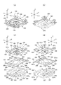
- FIG. 6 and 7 are an exploded perspective view of the optical unit 200 with a shake correction function according to the first embodiment of the present invention as viewed from the front side and an exploded perspective view as viewed from the rear side, respectively.
- FIG. 8 is an explanatory diagram of the movable module 1 of the optical unit with shake correction function 200 according to the first embodiment of the present invention and members connected to the movable module 1, and FIGS. 8A and 8B are respectively diagrams. They are the perspective view which looked at the movable module 1 and the member connected to this movable module 1 from the front side, and the perspective view seen from the rear side.
- the base 220, the rear stopper member 270, the front stopper member 290, and the fixed cover 260 are arranged from the rear side (lower side) to the front side (upper side). Are stacked and fixed in order.
- the base 220 has a function of supporting the movable module 1 so as to be swingable, and the rear stopper member 270 and the front stopper member 290 are configured to be swingable.
- the fixed cover 260 functions as a housing of the optical unit 200 with a shake correction function and also has a function of holding the shake correction coils 230x and 23y.
- a flexible substrate 300 and a spring member 280 (biasing member) shown in FIGS. 4 to 8 are arranged between the base 220 and the movable module 1.
- the flexible substrate 300 and the spring member 280 are attached to the movable module 1. It is connected.
- the flexible substrate 300 has a function of electrically connecting the shake detection sensor 170 and the shake correction magnetic drive mechanism to the outside, and the spring member 280 has a function of urging the movable module 1 toward the base 220. Yes.
- movable module 1 and arrangement of shake detection sensor 17 9 and 10 are respectively an exploded perspective view of the movable module 1 and the flexible substrate 300 used in the optical unit 200 with shake correction function according to the first embodiment of the present invention, and an exploded perspective view of the flexible substrate 300 viewed from the rear side. It is.
- the movable module 1 includes a module cover 160 that holds the lens driving module 1a inside.
- the module cover 160 has a rectangular shape when viewed from the Z-axis direction, and four side plate portions 162 extend from the outer peripheral edge of the rectangular top plate portion 161 to the rear side.
- the top plate portion 161 has a circular opening 161a.
- the rear end of the module cover 160 is open, and a metal sensor cover 180 (first electromagnetic shield member) is connected to the rear end of the module cover 160 so as to cover the opening.
- a metal sensor cover 180 first electromagnetic shield member
- the rear end portion of the module cover 160 is provided with a bent portion 169 protruding outward, and the bent portion 169 is a surface intersecting the Z axis at four corner portions.
- a module cover side flange portion 168 is provided which projects outwardly inwardly (in the plane orthogonal to the Z axis in this embodiment).
- the sensor cover 180 includes a bottom plate portion 181 and four side plate portions 182 that stand on the front edge at the outer peripheral edge of the bottom plate portion 181, and each of the four corner portions has a Z at the front edge of the side plate portion 182.
- a sensor cover side flange portion 188 is formed to project outward in a plane intersecting the axis (in this embodiment, in a plane orthogonal to the Z axis).
- the sensor cover side flange portion 188 and the module cover side flange portion 168 are formed to overlap in the Z-axis direction.
- Small holes 188 a and 168 a are formed in the sensor cover side flange portion 188 and the module cover side flange portion 168. Therefore, in this embodiment, a cylindrical member 199 having an inner peripheral surface formed with a female screw is fixed to the shaft portion with the shaft portion of the screw 198 passing through the small holes 188a and 168a.
- the module cover side flange portion 168 and the sensor cover side flange portion 188 are provided on the outer peripheral surface of the movable module 1 as shown in FIGS.
- the protrusions 103 projecting outward at the four corners of the movable module 1 are formed.
- the side plate portion 182 opposed in the Y-axis direction has a notch 182a formed at the front end edge thereof. For this reason, a gap that opens in the Y-axis direction is formed between the sensor cover 180 and the module cover 160 in a state where the sensor cover 180 and the module cover 160 are connected. Therefore, a part of the flexible substrate 300 can be disposed between the sensor cover 180 and the lens driving module 1a, and the drawer portion 350 of the flexible substrate 300 can be pulled out from the movable module 1 from one side in the Y-axis direction.
- the flexible substrate 300 has a shape in which a substantially rectangular sheet extending in the Y-axis direction is bent at three locations in the longitudinal direction (folded portions 301, 302, 303). For this reason, the flexible substrate 300 includes a lead-out portion 350 to the outside, a first flat plate portion 310 connected to the lead-out portion 350, a second flat plate portion 320 connected to the first flat plate portion 310 via a bent portion 301, A third flat plate portion 330 connected to the second flat plate portion 320 via the bent portion 302; and a fourth flat plate portion 340 connected to the third flat plate portion 330 via the bent portion 303.
- the 2nd flat plate part 320, the 3rd flat plate part 330, and the 4th flat plate part 340 are the shapes folded in order from the rear side to the front side in the Z-axis direction.
- the bent portions 301 and 303 are bent at an acute angle, while the bent portion 302 is gently curved into a U shape.
- the first flat plate portion 310 and the second flat plate portion 320 are disposed on the rear side (lower side) of the sensor cover 180, and the third flat plate portion 330 and the fourth flat plate portion 340 are formed of the sensor cover 180 and the lens. It arrange
- the shake detection sensor 170 is mounted on the lower surface of the third flat plate portion 330, and the lower surface of the shake detection sensor 170 is bonded and fixed to the sensor cover 180. Accordingly, the portion of the flexible substrate 300 drawn inside the movable module 1 is displaced integrally with the movable module 1, and the portion of the flexible substrate 300 drawn out from the movable module 1 is moved to the movable module 1. The near portion is deformed following the swing of the movable module 1.
- a reinforcing metal plate 380 is fixed to the upper surface of the third flat plate portion 330 via a flexible double-sided tape 370.
- the metal plate 380 is interposed between the shake detection sensor 170 and the image sensor 15 (see FIG. 2), and has a function of shielding the lower surface side of the image sensor 15.
- the imaging element 15 described with reference to FIG. 2 is electrically connected to the fourth flat plate portion 340 of the flexible substrate 300 via the substrate 154 (double-sided substrate), and the lens driving coils 30s and 30t are also spring pieces.
- the shake detection sensor 170 is a surface mount type gyroscope (angular velocity sensor) and detects angular velocity of two axes, preferably two axes orthogonal to each other. At the time of such detection, an excitation signal is input to the gyroscope, and camera shake is detected based on the phase difference between the output signal and the input signal. For this reason, when electromagnetic wave noise enters from the outside, the shake detection sensor 170 performs false detection, and the shake detection sensor 170 itself may be a source of electromagnetic noise.
- gyroscope angular velocity sensor
- the first flat plate portion 310 and the second flat plate portion 320 arranged on the rear side of the sensor cover 180 are formed with large-diameter round holes 310a and 320a. This is a cut-out portion for arranging a support mechanism 400 for swingably supporting the movable module 1 on the rear surface side of the cover 180.
- the flexible substrate 300 is arranged so as to avoid the support mechanism 400 by forming a cutout in the flexible substrate 300. For this reason, the space sandwiched between the base 220 and the movable module 1 can be effectively utilized as a space for routing the flexible substrate 300.
- a slit 300a extending in the Y-axis direction is formed at the center portion in the width direction.
- the first flat plate portion 310 continuously extends from the hole 310 a to the bent portion 302. Therefore, the flexible substrate 300 can be easily deformed in the width direction (X-axis direction) as much as the slit 300a and the holes 310a and 320a are formed. Further, since the arrangement of the flexible substrate 300 is symmetric in the X-axis direction, the force exerted by the flexible substrate 300 on the movable module 1 is the same even when the movable module 1 swings in any direction around the Y-axis.
- the movable module 1 can be properly swung, so that camera shake correction can be performed reliably.
- the flexible substrate 300 is provided with the bent portions 301 and 302 in the Y-axis direction at the portion drawn from the movable module 1, when the flexible substrate 300 is deformed when the movable module 1 is swung around the X-axis. The shape restoring force of this is unlikely to affect the swing of the movable module 1.
- FIG. 11 is an explanatory diagram of members constituting the support mechanism 400 and the like in the optical unit 200 with a shake correction function according to the first embodiment of the present invention
- FIGS. d are a perspective view of the base 220, the spring member 280, and the sensor cover 180 of the optical unit 200 with shake correction function as seen from the front side, a perspective view from the rear side, an exploded perspective view from the front side, and an exploded view from the rear side, respectively.
- It is a perspective view. 12A and 12B are an explanatory view and a cross section of the base 220, the spring member 280, and the sensor cover 180, respectively, of the optical unit with shake correcting function 200 according to Embodiment 1 of the present invention.
- FIG. 1 is an explanatory diagram of members constituting the support mechanism 400 and the like in the optical unit 200 with a shake correction function according to the first embodiment of the present invention
- FIGS. d are a perspective view of the base 220, the spring member 280, and the sensor cover 180
- the bottom plate portion 181 of the sensor cover 180 described with reference to FIGS. 4, 5, 9, and 10 has a central circular portion 186 that is recessed rearward when viewed from the front side.
- the central portion of the circular portion 186 is formed with a concave portion 187 (supporting receiving portion) that protrudes in a cylindrical shape with a bottom toward the front and opens at the lower surface.
- the base 220 arranged to face the sensor cover 180 on the rear side has a configuration in which four side plate parts 222 are erected from the outer peripheral edge of the rectangular bottom plate part 221 to the front side, and the side plate part is opposed in the Y-axis direction.
- a bottomed cylindrical support protrusion 227 that protrudes to the front side (upper side) is formed at the center portion of the bottom plate portion 221, and a hemispherical small protrusion 227 a is formed on the front end surface of the support protrusion 227. . Therefore, as shown in FIG.
- a bipot portion is formed between the base 220 of the fixed body 210 and the sensor cover 180 of the movable module 1 by the bottom lower surface 187a of the recess 187 and the small protrusion 227a of the support protrusion 227.
- the pivot portion constitutes a support mechanism 400 that allows the movable module 1 to swing with respect to the fixed body 210.
- the support mechanism 400 is disposed on the rear side of the shake detection sensor 170 at a position overlapping the shake detection sensor 170 in the Z-axis direction.
- the base 220 is a pressed product of a metal plate, and when viewed from the front side (upper side), the bottom plate portion 221 has a space between the outer peripheral region 221a and the central region 221b where the support protrusions 227 are formed.
- a recess 226 that is recessed rearward is formed, and the recess 226 is formed so as to surround three sides of the central region 221b where the support protrusion 227 is formed.
- a slit 228 is formed in the central region 221b so as to surround three sides of the region where the support protrusion 227 is formed, and the plate extending in the Y-axis direction by the slit 228.
- a spring portion 229 is formed. Accordingly, the support protrusion 227 is formed at the tip of the leaf spring portion 229. Therefore, when the leaf spring portion 229 is deformed in the Z-axis direction, the entire support mechanism 400 is displaced in the Z-axis direction.
- the leaf spring portion 229 is positioned slightly in front of the rear surface of the base 220. For this reason, as shown in FIGS. 4A and 4B, the rear surface of the leaf spring portion 229 is positioned in front of the rear surface of the base 220 and the rear end edge of the fixed cover 260 by a predetermined dimension G10.
- a spring member 280 that biases the movable module 1 toward the base 220 is disposed between the sensor cover 180 and the base 220 of the movable module 1, and the spring member 280 is connected to the bottom lower surface 187 a of the recess 187.
- An urging force is generated in a direction in which the small protrusion 227a of the support protrusion 227 abuts.
- the spring member 280 is a flat spring having a flat rectangular shape, and is formed by pressing a thin metal plate such as phosphor bronze, beryllium copper, nonmagnetic SUS steel, or the like, or etching using a photolithography technique. It is.
- fixed body side connecting portions 281 connected to the fixed body 210 are formed at four corner portions.
- the fixed body side connecting portion 281 is fixed to the rear stopper member 270 shown in FIGS. 4 to 7 among a plurality of members constituting the fixed body 210.
- small holes 281a are formed in the fixed body side connecting portion 281 of the spring member 280, while small protrusions 277a are formed at four corners on the rear surface of the rear stopper member 270.
- the fixed body side connecting portion 281 can be connected to the fixed body 210.
- a substantially rectangular movable module side connecting portion 282 that is connected to the sensor cover 180 of the movable module 1 is formed in the central portion of the spring member 280.
- a sensor is provided in the central region of the movable module side connecting portion 282.
- a circular hole 282a into which a circular portion 186 protruding rearward from the bottom plate portion 181 of the cover 180 is formed is formed.
- the movable module side connecting portion 282 is fixed to the rear surface of the bottom plate portion 181 of the sensor cover 180 by a method such as adhesion.
- the spring member 280 has a gimbal spring shape including four narrow arm portions 283 having both ends connected to a central movable module side connecting portion 282 and four fixed body side connecting portions 281.
- each of the four arm portions 283 is configured to extend in the X axis direction or the Y axis direction along the side portion of the movable module side connecting portion 282.
- the spring member 280 is mounted on the optical device 200 with shake correction function, and the position of the movable module side connecting portion 282 in the Z-axis direction (the direction of the optical axis L) is determined by the support protrusion 227 of the base 220 being the sensor.
- the position is the same as the position in contact with the bottom lower surface 187 a of the recess 187 of the cover 180.
- the movable module side connecting portion 282 is located in front of the fixed body side connecting portion 281. For this reason, the arm portion 283 biases the movable module 1 toward the base 220.
- the four arm portions 283 all extend from the fixed body side connecting portion 281 in the same circumferential direction, and the four arm portions 283 have the same shape and size around the optical axis. They are arranged at equiangular intervals. For this reason, all the four arm portions 283 are rotationally symmetric at 90 degrees, 180 degrees, and 270 degrees.
- the spring member 280 includes a movable module side connecting portion 282 made of a flat plate portion having a large area, and is connected to the sensor cover 180 over a wide area by the movable module side connecting portion 282.
- the spring member 280 generates a biasing force in a direction in which the bottom lower surface 187a of the recess 187 and the small protrusion 227a of the support protrusion 227 come into contact with each other, and when no external force is applied to the movable module 1, the optical axis of the movable module L is held in a posture parallel to the Z axis.
- the first flat plate portion 310 and the second flat plate portion 320 of the flexible substrate 300 described with reference to FIGS. 9 and 10 are disposed between the spring member 280 and the base 220 on the rear side of the sensor cover 180. Is done. Therefore, in the spring member 280, the two fixed body side connecting portions 281 are connected by the beam portion 284 in the X axis direction, but the beam portion 284 is not formed in the Y axis direction, and the space between the fixed body side connecting portions 281 is not provided. There is a notch. For this reason, the flexible substrate 300 can be passed between the fixed body side connecting portions 281 on one side in the Y-axis direction.
- the portion overlapping the arm portion 283 of the spring member 280 in the Z-axis direction is compared to the region where the movable module side connecting portion 282 of the spring member 280 is connected.
- a recessed portion 181e is formed to be recessed toward the direction away from the arm portion 283 (front side). For this reason, a gap is interposed between the bottom plate portion 181 and the arm portion 283 of the sensor cover 180. Therefore, the bottom plate portion 181 of the sensor cover 180 is not in contact with the arm portion 283 at all, and even when the movable module 1 swings and the spring member 280 is deformed, the bottom plate portion 181 of the sensor cover 180 The arm portion 283 does not come into contact.
- a rectangular plate-shaped camera shake correction magnet 240x (which forms the first shake correction magnetic drive mechanism 250x)
- a rectangular plate-shaped image stabilization magnet constituting the second image stabilization magnetic drive mechanism 250y is provided on the outer surface of the other two side plate portions 162 facing each other in the X-axis direction.
- 240y (second camera shake correction magnet) is held.
- each of the image stabilization magnets 240x and 240y is a rectangular flat permanent magnet.
- the image stabilization magnets 240x and 240y are constituted by two flat plate permanent magnets arranged in the Z-axis direction.
- the outer surface side and the inner surface side are magnetized to different poles. ing. Moreover, the magnetization direction is reverse in the two flat permanent magnets arranged in the Z-axis direction. As for the camera shake correction magnets 240x and 240y, two permanent magnets may be magnetized with different polarities.
- a camera shake correction coil 230x (first camera shake correction) constituting the first camera shake correction magnetic drive mechanism 250x is provided.
- a camera shake correction coil 230y (second camera shake) constituting the second shake correction magnetic drive mechanism 250y is provided.
- the correction coil is fixed by adhesion.
- the camera shake correction coils 230x and 230y face the camera shake correction magnets 240x and 240y, respectively.
- each end portion of the camera shake correction coils 230x and 230y is electrically connected to the outside through the flexible substrate 300 or another flexible substrate.
- a small opening 262a is formed in the side plate portion 262 of the fixed cover 260. The opening 262a fixes the camera shake correction coils 230x and 230y to the side plate portion 262, and then applies a reinforcing adhesive. It is used for etc.
- the first shake correction magnetic drive mechanism 250x that swings the movable module 1 around the X axis in pairs at two locations facing each other with the support mechanism 400 interposed therebetween in the Y axis direction.
- the two shake correction coils 230x generate the magnetic drive force in the same direction around the X axis when the two shake correction coils 230x are energized.
- Wired connection Accordingly, the two first shake correction magnetic drive mechanisms 250x apply moments in the same direction around the X axis passing through the support mechanism 400 to the movable module 1 when the two camera shake correction coils 230x are energized.
- the second shake correction magnetic drive mechanism 250y is configured which makes the movable module 1 swing around the Y axis in pairs at two locations facing each other with the support mechanism 400 interposed therebetween in the X axis direction.
- the two shake correction coils 230y are wired so that the movable module 1 generates a magnetic drive force in the same direction around the Y axis when energized. ing. Accordingly, the two second shake correction magnetic drive mechanisms 250y apply moments in the same direction around the Y axis passing through the support mechanism 400 to the movable module 1 when the two camera shake correction coils 230y are energized.
- the module cover 160 is made of a magnetic material and functions as a yoke for the camera shake correction magnets 240x and 240y. Further, in the module cover 160, a bent portion 169 that is bent slightly outward is formed at the rear end portion, and the bent portion 169 has a function of improving the magnetic flux collecting performance.
- a shake detection sensor 170 such as a gyroscope for detecting a shake during shooting is mounted on the movable module 1.
- the control unit mounted on the camera-equipped mobile phone energizes one or both of the shake correction coil 230 x and the shake correction coil 230 y, and moves the movable module 1 to X. Oscillate in one and both around the axis and around the Y axis. If such swinging is combined, the movable module 1 is swung with respect to the entire XY plane. Therefore, it is possible to surely correct all camera shakes assumed for a camera-equipped mobile phone or the like.
- the shake detection sensor 170 is mounted on the movable module 200 itself, and the control unit (not shown) first controls the angular velocity detected by the shake detection sensor 170 to be zero.
- the shake correction magnetic drive mechanism 250x and the second shake correction magnetic drive mechanism 250y are closed-loop controlled. Further, the control unit (not shown) controls the first shake correction magnetic drive mechanism 250x and the second shake correction magnet so that the integral value of the angular velocity detected by the shake detection sensor 170, that is, the angular displacement becomes zero.
- the drive mechanism 250y is controlled in a closed loop.
- the shake detection sensor 170 is mounted on the movable module 1. For this reason, since the shake of the optical axis L is directly detected by the shake detection sensor 170, the shake can be accurately corrected.
- the movable module 1 since the movable module 1 is swung around the support mechanism 400 configured on the rear side of the movable module 1, the deformation of the flexible substrate 300 is extremely small. Accordingly, since the shape restoring force when the flexible substrate 300 is deformed is small, the movable module 1 can be swung quickly.
- the position in the Z-axis direction of the magnetic center position (the center position of the shake correction magnets 240x and 240y) where the magnetic force acts on the movable module 1 is The center of the movable module 1 in the Z-axis direction and the front (away from the center) of the optical unit 200 with shake correction function in the Z-axis direction. Therefore, there is an advantage that the magnetic drive force required for the first shake correction magnetic drive mechanism 250x and the second shake correction magnetic drive mechanism 250y to swing the movable module 1 may be small.
- the position in the Z-axis direction of the magnetic center position where the magnetic force acts on the movable module 1 is the center in the Z-axis direction of the movable module 1
- the optical module 200 with shake correction function is on the rear side (near position) from the center in the Z-axis direction, the movable module 1 can be swung greatly with a slight displacement, so that the response to shake correction is excellent. There is an advantage that.
- FIG. 13 is an explanatory diagram of members that limit the movable range of the movable module 1 in the optical unit 200 with shake correction function according to Embodiment 1 of the present invention
- FIGS. , (D) is a perspective view seen from the front side, a perspective view seen from the rear side, an exploded perspective view seen from the front side, and a rear side, respectively, with the rear side stopper member 270 and the front side stopper member 290 being arranged on the movable module 1.
- FIG. 14 is an explanatory diagram of a mechanism for limiting the movable range of the movable module 1 in the optical unit 200 with shake correction function according to the first embodiment of the present invention, and FIGS. 14 (a), 14 (b), and 14 (c).
- FIG. 1A is a plan view of the optical unit with shake correction function according to Embodiment 1 of the present invention when the rear stopper member is disposed on the movable module, as viewed from the front side
- the optical unit with shake correction function in FIG. 2 is a Y2-Y2 ′ cross-sectional view passing near the corner of 200, and an X2-X2 ′ cross-sectional view passing near the corner of the optical unit 200 with shake correction function in FIG.
- a rectangular frame-shaped front stopper member 290 and a rear stopper member 270 are arranged around the movable module 1,
- the movable module 1 is bidirectional in the X axis direction, bidirectional in the Y axis direction, bidirectional in the Z axis direction, bidirectional in the X axis direction, and in the Y axis direction.
- the movable range in both directions and around the Z axis is limited.
- the rear stopper 270 when viewed from the front side, has four corners at the corners of the movable module 1 in the X-axis direction. Further, an inner wall 272a facing the protrusion 103 protruding in the Y-axis direction via a slight gap GX1 outside the X-axis direction and a slight gap GY1 outside the protrusion 103 in the Y-axis direction. And an inner wall 272b facing each other.
- the bidirectional movable range of the movable module 1 in the X-axis direction, in the Y-axis direction, in the bidirectional direction around the X axis, in the bidirectional direction around the Y axis, and in the bidirectional direction around the Z axis is limited.
- the rear stopper 270 includes a plate-like portion 274 that faces the protrusion 103 on the rear side in the Z-axis direction. Further, in the front stopper 290, the corner portion 297 of the frame portion faces the protrusion 103 on the front side in the Z-axis direction. For this reason, the bidirectional movable range in the Z-axis direction of the movable module 1 is limited.
- the front side stopper member 290 and the rear side stopper member 270 are made of resin, and have shock absorption and vibration absorption unlike metal. For this reason, even if the movable module 1 comes into contact with the front stopper member 290 and the rear stopper member 270, no excessive sound or vibration is generated.
- the support protrusion 227 of the base 220 is fitted in the concave portion 187 of the sensor cover 180, and in this embodiment, the support module 400 also uses the support mechanism 400.
- Bidirectional movable ranges in the X-axis direction and in the Y-axis direction are limited. That is, as shown in FIG. 4, there is only a slight gap GX2 in the X-axis direction between the outer peripheral surface of the support protrusion 227 and the inner peripheral surface of the recess 187, and a slight amount in the Y-axis direction. Only the gap GY2 is vacant.
- the small protrusion 227 a of the support protrusion 227 of the base 220 abuts on the bottom lower surface 187 a of the recess 187, and even in this support mechanism 400, Movement to the rear of the direction is restricted.
- the small projection is maintained until the projection 103 of the movable module 1 contacts the plate-like portion 274 of the rear stopper 270.
- the load on 227a and the bottom lower surface 187a of the recess 187 is concentrated, and the small protrusion 227a and the bottom lower surface 187a of the recess 187 may be deformed.
- the support protrusion 227 is formed at the tip end portion of the leaf spring portion 229 formed on the base 220, the entire support mechanism 400 is moved when displaced to the rear side in the Z-axis direction of the movable module 1. Displacement in the Z-axis direction.
- the leaf spring portion 229 is positioned on the front side by a predetermined dimension G10 with respect to the rear surface of the base 220 and the rear end edge of the fixed cover 260. For this reason, even if the movable module 1 is suddenly displaced to the rear side in the Z-axis direction due to an impact such as dropping, and the leaf spring part 229 is displaced to the rear side, the leaf spring part 229 remains on the rear surface of the base 220 or the fixed cover 260. It does not protrude rearward from the rear edge.
- the first shake correction magnetic drive mechanism 250x that is paired in two places on both sides of the support protrusion 227 in the Y-axis direction is disposed.
- a second shake correction magnetic drive mechanism 250y is arranged in two pairs on both sides of the support protrusion 227 in the X-axis direction.
- the two first shake correction magnetic drive mechanisms 250x each generate a magnetic force that causes the movable module 1 to swing in the same direction
- the two second shake correction magnetic drive mechanisms 250y each cause the movable module 1 to move. A magnetic force that swings in the same direction is generated.
- the first shake correction magnetic drive mechanism 250x is disposed only on one side with respect to the support protrusion 227, or a configuration in which the second shake correction magnetic drive mechanism 250y is disposed only on one side with respect to the support protrusion 227, and
- the driving ability is stable, camera shake can be corrected with high accuracy.
- the positional relationship between the shake correction magnet 240x and the shake correction coil 230x constituting the first shake correction magnetic drive mechanism 250x is two first shake correction.
- the other first shake correction magnetic drive mechanism 250x is used to correct the camera shake in one of the first shake correction magnetic drive mechanisms 250x. Since the displacement of the position of the magnet 240x and the shake correction coil 230x is corrected, that is, the direction in which the magnetic drive force increases, the drive capability of the first shake correction magnetic drive mechanism 250x is stable. . Such an action is the same in the second shake correction magnetic drive mechanism 250y.
- the shake detection sensor 170 since the shake detection sensor 170 is mounted on the movable module 1, the shake detection sensor 170 detects the shake of the optical axis L directly. Therefore, the camera shake of the movable module 1 can be accurately corrected.
- the configuration of the movable module 1 is complicated in terms of the drawing of the flexible substrate 300.
- the module cover 160 and the sensor are added to the movable module 1. Since the cover 180 is used, the assembly of the movable module 1 is easy. Further, when the module cover 160 and the sensor cover 180 are connected, the module cover 160 and the sensor cover side flange 188 that protrude outward from the module cover 160 and the sensor cover 180 are used.
- the module cover side flange portion 168 and the sensor cover side flange portion 188 are detachably connected by screws 198. For this reason, it is easier to disassemble the movable module 1, collect the shake detection sensor 170, and reuse it.
- the shaft portion of the screw 198 is fixed to a cylindrical member 199 having a screw hole on the inner periphery to which the screw 198 is screwed.
- the movable module 1 can be reduced in size and weight.
- the movable module 1 has a rectangular shape when viewed from the direction of the optical axis L, and the module cover side flange portion 168 and the sensor cover side flange portion 188 are projected at rectangular corner portions. For this reason, there is no need to fasten the module cover side flange portion 168 and the sensor cover side flange portion 188 at the portion corresponding to the side portion of the movable module 1, so the portion corresponding to the side portion of the movable module 1 is utilized.
- a shake correction magnetic drive mechanism (a first shake correction magnetic drive mechanism 250x and a second shake correction magnetic drive mechanism 250y) can be disposed.
- the protrusion 103 is formed by the module cover side flange portion 168 and the sensor cover side flange portion 188 on the outside of the movable module 1, the protrusion 103, the front stopper member 290, the rear stopper member 270, , Bidirectional in the X-axis direction, bidirectional in the Y-axis direction, bidirectional in the Z-axis direction, bidirectional in the X-axis direction, bidirectional in the Y-axis direction, and in the Z-axis direction.
- a stopper mechanism for limiting the movable range is formed. For this reason, since the movable module 1 is not displaced excessively, the plastic deformation of the spring member 280 can be prevented.
- the protrusion 103 has a two-piece structure of the module cover side flange portion 168 and the sensor cover side flange portion 188, the protrusion 103 has sufficient strength to constitute a stopper mechanism. For this reason, since the module cover side flange portion 168 and the sensor cover side flange portion 188, and further, the module cover 160 and the sensor cover 180 can be thinned, the movable module 1 can be reduced in size and weight. .
- the support mechanism 400 including the bipot portion is configured between the base 220 of the fixed body 210 and the sensor cover 180 of the movable module 1, the movable module 1 is moved in the Z-axis direction. Can be prevented.
- the gimbal spring-like leaf spring used as the spring member 280 has the long arm portion 283, the linearity of the deformation amount (displacement amount) and the spring force is high, so that it is easy to correct the shake of the movable module.
- the sensor cover 180 is made of metal and is electrically connected to the ground. For this reason, the sensor cover 180 functions as a first electromagnetic shield member that covers the rear side of the shake detection sensor 170. Further, a metal plate 380 is interposed between the shake detection sensor 170 and the image sensor 15 on the front side of the shake detection sensor 170, and the metal plate 380 is also electrically connected to the ground. For this reason, the metal plate 380 functions as a second electromagnetic shield member that shields the lower surface side of the image sensor 15. Therefore, it is possible to reliably prevent the occurrence of abnormality due to electromagnetic wave noise that has entered the shake detection sensor 170 from the outside or abnormality due to electromagnetic wave noise emitted from the shake detection sensor 170.
- the shake detection sensor 170 is disposed at the rear end of the movable module 1, and a metal sensor cover 180 is attached to the movable module 1 so as to cover the shake detection sensor 170 on the rear side. 180 constitutes the rearmost end of the movable module 1. Therefore, the metal sensor cover 180 functions as a first electromagnetic shield member, and also includes a support receiving portion (concave portion 187) when the support mechanism 400 for the movable module 1 is configured, a connection portion with the spring member 280, and the like. , responsible for other functions. Therefore, it is possible to reliably prevent the occurrence of abnormality due to electromagnetic noise entering the shake detection sensor 170 from the outside or abnormality due to electromagnetic noise emitted from the shake detection sensor 170 with a small number of parts.
- magnets in both the first shake correction magnetic drive mechanism 250x and the second shake correction magnetic drive mechanism 250y, magnets (camera shake correction magnets 240x and 240y) are provided on the movable module 1 side which is the movable body side. Since the coils (shake correction coils 230x and 230y) are held on the fixed body 210 side, the number of wires for the movable module 1 on the movable body side may be small, and the wiring structure can be simplified. . Further, since the number of turns of the camera shake correction coils 230x and 230y can be increased on the fixed body 210 side, a large driving force can be exhibited.
- FIG. 15 is an explanatory view showing Modification Example 1 for electrically connecting the movable module 1 and the outside in the optical unit 200 with shake correcting function according to Embodiment 1 of the present invention. Note that the basic configuration of the first embodiment and the other embodiments described below are the same as those described with reference to FIGS. Therefore, common parts are shown with the same reference numerals, and description thereof is omitted.
- the end of the drawer portion 350 of the flexible substrate 300 electrically connected to the movable module 1 is connected to a connector (not shown) arranged outside.
- the connector 510 is fixed to the end portion of the drawer portion 350 of the flexible substrate 300. According to such a configuration, the movable module 1 and the outside can be electrically connected via the connector 510.
- FIG. 16 is an explanatory diagram showing a second modification for electrically connecting the movable module 1 and the outside in the optical unit with shake correction function 200 according to the first embodiment of the present invention.
- the electrical connection between the movable module 1 and the outside is performed by the connector 520 fixed to the side surface of the fixed cover 260 or the fixed body 210. This is done via a connector 530 fixed to the rear surface (lower surface).
- FIG. 17 is an explanatory diagram showing a third modification for electrically connecting the movable module 1 and the outside in the optical unit 200 with a shake correction function according to the first embodiment of the present invention.
- electrical connection between the movable module 1 and the outside is performed by connecting connectors 540 and 550 fixed to the rear surface (lower surface) of the fixed body 210. Is done through.
- a terminal 541 is formed on the side surface of the connector 540 shown in FIG. 17A
- a terminal 551 is formed on the rear surface (lower surface) of the connector 550 shown in FIG.
- a shake correction function by simply mounting the rear end portion (lower end) of the optical unit 200 with shake correction function in a socket configured in a device on which the optical unit 200 with shake correction function is mounted.
- the optical unit 200 and the outside are electrically connected via connectors 540 and 550.
- a connector having terminals formed on the side surface and the rear surface (lower surface) may be used.
- FIG. 18 is an explanatory diagram showing a fourth modification for electrically connecting the movable module 1 and the outside in the optical unit 200 with a shake correction function according to the first embodiment of the present invention.
- the electrical connection between the movable module 1 and the outside is the rigid substrate 560 fixed to the side surface of the fixed cover 260 or the fixed body 210. This is done via a connector 570 fixed to the rear surface (lower surface).
- the rigid substrates 560 and 570 have a structure in which electrodes 561 and 571 are formed on a paper-impregnated substrate such as a phenol resin or an epoxy resin, a glass epoxy substrate, and the like. When mounted on the device, soldering or the like is performed on the electrodes 561 and 571.
- the movable module 1 may be swingably supported by using one or a plurality of leaf spring-like spring members 280 shown in FIG. 6 without using the pivot portion.
- An example will be described as Embodiments 2 and 3.
- FIG. 19 is an explanatory diagram of an optical unit with a shake correction function for photographing according to Embodiment 2 of the present invention.
- FIGS. 19A and 19B each show the optical unit with a shake correction function from the subject side.
- FIG. 5 is a perspective view of the optical unit with a shake correction function as viewed from the side opposite to the subject side.
- FIG. 20 is an explanatory diagram of a fixed body and a movable module of the optical unit with shake correction function according to the second embodiment of the present invention, and FIGS. 20 (a), (b), and (c) each show the fixed body.
- FIG. 20 is an explanatory diagram of a fixed body and a movable module of the optical unit with shake correction function according to the second embodiment of the present invention, and FIGS. 20 (a), (b), and (c) each show the fixed body.
- FIG. 20 is an explanatory diagram of a fixed body and a movable module of the optical unit with shake correction function according to the second embodiment of the
- FIG. 3 is a perspective view as seen from the side opposite to the subject side, a perspective view of the movable module as seen from the side opposite to the subject side, and a perspective view of the movable module as seen from the subject side.
- FIG. 20A the illustration of the fixed cover is omitted.
- the basic configuration of the second embodiment and the third embodiment to be described later is the same as that of the first embodiment. Therefore, as much as possible, parts having common functions are described with the same reference numerals.
- the optical unit 200 with a shake correction function shown in FIGS. 19 and 20 is a thin camera used in an optical device such as a camera-equipped mobile phone, as in the first embodiment, and has a substantially rectangular parallelepiped shape as a whole.
- the optical unit 200 with shake correction function includes a coil holder 1260, a frame 1270 that is fixed on the opposite side (+ Z axis direction) to the subject side ( ⁇ Z axis direction) of the coil holder 1260, and a coil holder 1260.
- a box-shaped fixed cover 1230 for holding the frame 1270 inside, and the fixed body 210 is constituted by the coil holding body 1260, the frame 1270, and the fixed cover 1230.
- the movable module 1 including the lens driving module 1a is arranged inside the fixed body 210 having such a configuration.
- a rectangular window-shaped opening 1231a is formed in the upper plate portion 1231 positioned at the end on the subject side of the fixed cover 1230.
- the region is an opening 1231a.
- the end of the fixed cover 1230 opposite to the subject side is an open end.
- a shake correction magnetic drive mechanism 250 for performing shake correction by displacing the lens drive module 1a is formed inside the fixed cover 1230.
- the fixed body 210, the movable module 1 holding the lens drive module 1a inside, and the plate-like spring connected to the fixed body 210 and the movable module 1 are used.
- a vibration correcting magnet that generates a magnetic driving force that relatively displaces the movable module 1 with respect to the fixed body 210 is provided between the movable module 1 and the fixed body 210.
- a drive mechanism 250 is configured.
- a sensor flexible board 1410 and a driving flexible board 1420 are disposed on the opposite side to the subject side.
- the coil holder 1260 includes post portions 1261 at four corner portions, and the upper end portions of the post portions 1261 are connected by crosspieces 1262. Has been. A hole through which a screw 1279 (see FIG. 19B) is passed is formed in the first support column portion 261. Two X-side coils 1571 that sandwich the movable module 1 on both sides in the X-axis direction and two Y-side coils 1572 that sandwich the movable module 1 on both sides in the Y-axis direction are fixed to the four side surfaces of the coil holder 1260. Has been.
- the X-side coil 1571 and the Y-side coil 1572 are air-core coils wound in a rectangular frame shape, and include two effective side portions that face each other in the Z-axis direction.
- a rectangular frame-shaped frame 1270 is arranged on the coil holding body 1260 on the opposite side to the subject side.
- the frame 1270 includes a rectangular frame-shaped portion 1271 and a cylindrical portion 1272 that protrudes toward the coil holding body 1260 at four corners of the frame-shaped portion 1271, and a screw 1279 (see FIG. 19 (b)) is formed.
- the corner portion of the coil holder 1260 overlaps the cylindrical portion 1272 of the frame 1270. Therefore, the coil holder 1260 and the frame 1270 can be fixed by the screws 1279 at the four corners.
- an auxiliary substrate 1450 is used to supply power to the X-side coil 1571 and the Y-side coil 1572, and the auxiliary substrate 1450 has an end portion that connects the frame 1270 and the coil holder 1260 with screws 1279. It is fixed to the lower surface of the frame 1270 (surface opposite to the subject side).
- FIG. 21 is an exploded perspective view of the movable module 1 of the optical unit 200 with a shake correction function according to the second embodiment of the present invention. 19, 20 (b), (c) and FIG. 21, in the optical unit 200 with shake correction function of the present embodiment, the movable module 1 includes the lens driving module 1a and the lens driving module 1a inside.
- a pressing member 1380 arranged to be overlapped on one side.
- the module cover 1390 includes a rectangular tubular body 1398, and an X-side magnet 1581 that sandwiches the movable module 1 on both sides in the X-axis direction and the movable module 1 on the outer surface of the rectangular tubular body 1398. Is fixed to a Y-side magnet 1582 that sandwiches the Y-axis on both sides in the Y-axis direction.
- Each of the X-side magnet 1581 and the Y-side magnet 1582 is composed of two flat magnet pieces arranged in the Z-axis direction, and the two magnet pieces are magnetized to poles having different inner and outer surfaces. Are arranged so as to have different poles in the direction of the optical axis L.
- the module cover 1390 is made of a magnetic plate and functions as a back yoke.
- the inside of the rectangular cylindrical body 1398 is composed of a sensor housing 1396 in which a shake detection sensor 170 (angular velocity sensor / gyroscope) is housed, and a photographing unit housing 1397 in which the lens driving module 1a is housed.
- the part 1396 includes an upper plate part 1394.
- a block 1305 is positioned below the upper plate portion 1394, and the shake detection sensor 170 is disposed below the block 1305.
- the subject side end of the rectangular tube-shaped body 1398 corresponding to the photographing unit housing portion 1397 is located further on the subject side than the upper plate portion 1394 of the sensor housing portion 1396, and such photographing unit.
- Triangular support plate portions 1395 are formed at the four corner portions of the accommodating portion 1397.
- a connecting portion 1393 protruding toward the outer peripheral side is formed at the end opposite to the subject side, and the four connecting portions are formed.
- Each of the portions 1393 is formed with a hole through which the screw 1108 is passed.
- the lens driving module 1a In the lens driving module 1a, four triangular recesses 1102 that are recessed in the direction of the optical axis L are formed at the end of the object side that overlaps the support plate 1395 of the module cover 1390, and the lens driving module 1a is attached to the module cover.
- the support plate portion 1395 of the module cover 1390 fits into the recess 1102 of the lens drive module 1a.
- two projections 1103 are formed on the end surface located on the ⁇ Y axis side, and the projections 1104 are formed on both end portions of the end surface located on the + Y axis side. Is formed.
- the substrate main body of the sub-substrate 1440 of the driving flexible substrate 1420 is connected to the end surface of the lens driving module 1a opposite to the subject side.
- the sensor holding plate 1370 includes a rectangular frame portion 1371 and a cylindrical portion 1372 projecting toward the module cover 1390 at each diagonal position of the rectangular frame portion 1371.
- a through hole for stopping the screw 1108 is formed in the cylindrical portion 1372, and a hole for stopping the screw 1109 is formed in a pair of side portions facing each other in the rectangular frame portion 1371 and the other one side portion. 1371a is formed.
- two notches 1371c for holding the elastic spacer 1106 inside are formed at the inner edge of the side portion where one hole 1371a is formed in the rectangular frame portion 1371.
- the pressing member 1380 includes a rectangular flat plate portion 1381, two seat plate portions 1386 that protrude toward the sensor holding plate 1370 at a pair of opposite sides of the flat plate portion 1381, and one other side of the flat plate portion 1381. 1 has a seat plate portion 1385 projecting toward the sensor holding plate 1370, and the seat plate portions 1385 and 1386 have holes through which screws 1109 are passed.
- a driving flexible substrate 1420 is disposed on the opposite side of the subject 210 with respect to the fixed body 210.
- the board 1420 includes a main board 1430 and a sub board 1440 connected to the main board 1430.
- the main substrate 1430 has a substrate main body portion 1431 having a shape in which two rectangular portions are connected, and two belt-like shapes extending from both end portions in the width direction (X-axis direction) of the substrate main body portion 1431 toward the + Y-axis direction.
- the lead-out portions 1432 and 1433 are provided.
- the sub-substrate 1440 extends in the + Y-axis direction from a rectangular substrate body (not shown) and a portion located slightly inside the width direction (X-axis direction) in the width direction (X-axis direction) of the substrate body.
- Band-shaped connecting portions 1442 and 1443 that are bent toward both sides in the X-axis direction are provided.
- the leading ends of the routing portions 1432 and 1433 of the main substrate 1430 and the leading ends of the strip-like connection portions 1442 and 1443 of the sub substrate 1440 are joined, and the main substrate 1430 and the sub substrate 1440 are integrated.
- the main substrate 1430 and the sub-substrate 1440 are electrically connected to each other while constituting the flexible substrate 1420 for use.
- a sensor flexible substrate 1410 In the optical unit 200 with a shake correction function, a sensor flexible substrate 1410 is disposed on the side opposite to the subject side with respect to the lens driving module 1a.
- the sensor flexible substrate 1410 includes a rectangular substrate main body portion 1411, strip-shaped lead portions 1412 and 1413 extending from both end portions in the width direction (X direction) of the substrate main body portion 1411 toward the + Y-axis direction, and a lead portion. 1412 and 1413, and a wide sensor mounting portion 1414 that connects the tip portions of each of them.
- the sensor flexible substrate 1410 includes a bent portion 1416 extending from the sensor mounting portion 1414 at a portion sandwiched between the lead portions 1412 and 1413, and the bent portion 1416 is connected to the sensor mounting portion 1414. After being bent at a right angle in the out-of-plane direction toward the subject side in the vicinity, it is bent toward one side in the Y-axis direction.
- a shake detection sensor 170 is mounted on the sensor mounting portion 1414, and a block 1305 is mounted inside the bent portion 1416.
- the block 1305 has a function of pressing and fixing the shake detection sensor 170.
- the spring member 600 includes an inner movable module side coupling portion 610 coupled to the movable module 1, an outer stationary body side coupling portion 620 coupled to the stationary body 210, and a movable module.
- the side connection part 610 and the arm part 630 extending between the fixed body side connection part 620 are provided.
- the movable module side connection part 610 and the fixed body side connection part 620 have holes through which screws 1108 and screws 1279 are passed. Each is formed.
- the spring member 600 is made of a nonmagnetic metal such as beryllium copper or a nonmagnetic SUS steel material, and is formed by pressing a thin plate having a predetermined thickness or etching using a photolithography technique.
- the spring member 600 is formed in a rectangular frame shape as a whole, and the movable module side connecting portion 610 and the fixed body side connecting portion 620 are all arranged at the four corner portions of the spring member 600.
- Each of the four arm portions 630 extends from the movable module side connecting portion 610 while being bent at a right angle in the same circumferential direction, and extends to the fixed body side connecting portion 620.
- the movable module 1 is supported by the single spring member 600 so as to be swingable.
- the shake detection sensor 170 and the sensor mounting portion 1414 of the sensor flexible substrate 1410 are provided on the surface opposite to the side where the shake detection sensor 170 is mounted.
- a solid conductive pattern 1414a is formed at the overlapping position.
- the conductive pattern 1414a is connected to the ground, and functions as a first electromagnetic shield member that overlaps the shake detection sensor 170 at the rear.
- the block 1305 disposed on the front side of the shake detection sensor 170 may be made of metal, and the block 1305 may be electrically connected to the ground. According to this configuration, the block 1305 can be used as the second electromagnetic shield member that covers the front side of the shake detection sensor 170.
- FIG. 22 is an explanatory diagram of an optical unit with a shake correction function for photographing according to Embodiment 3 of the present invention.
- FIGS. 22 (a) and 22 (b) show the optical unit with a shake correction function from the subject side, respectively.
- FIG. 5 is a perspective view of the optical unit with a shake correction function as viewed from the side opposite to the subject side.
- FIG. 23 is an explanatory diagram of a fixed body and a movable module of the optical unit with shake correction function according to the third embodiment of the present invention.
- FIG. 6 is a perspective view of the movable module viewed from the subject side, a perspective view of the movable module viewed from the subject side, and a perspective view of the movable module viewed from the side opposite to the subject side.
- FIG. 23A the illustration of the fixed cover is omitted.
- portions having common functions are denoted by the same reference numerals as much as possible.
- the optical unit 200 with a shake correction function shown in FIGS. 22 and 23 is a thin camera used for a camera-equipped mobile phone as in the first embodiment, and has a substantially rectangular parallelepiped shape as a whole.
- the optical unit 200 with shake correction function is generally connected to the fixed body 210 including the fixed cover 1230 and the coil holding body 1260, the movable module 1 that holds the lens driving module 1a inside, and the fixed body 210 and the movable module 1.
- a plate-like spring member 600 and a shake correction magnetic drive mechanism 250 that generates a magnetic drive force that causes the movable module 1 to be displaced relative to the fixed body 210 between the movable module 1 and the fixed body 210 are provided. Yes.
- the spring member 600 includes an inner movable module side coupling portion 610 coupled to the movable module 1, an outer stationary body side coupling portion 620 coupled to the stationary body 210, a movable module side coupling portion 610, and a stationary body side coupling portion 620.
- the arm part 630 extended between the two is provided.
- a rectangular window-shaped opening 1211 a is formed in the upper plate portion 1211 located at the subject-side end of the fixed cover 1230.
- the coil holder 1260 used for the fixed body 210 is disposed on the object side with respect to the first coil holding member 1270 having a rectangular frame shape located on the opposite side to the object side and the first coil holding member 1270.
- the first coil holding member 1270 includes first coils 1541, 1542, 1543, and 1544 that are held on the side surfaces of the second coil holding member 1280.
- second coils 1551, 1552, 1553, and 1554 are held on the side surfaces of the second coil holding member 1280.
- the first coils 1541, 1542, 1543, and 1544 and the second coils 1551, 1552, 1553, and 1554 are air-core coils wound in a rectangular frame shape, and have two effective side portions that face each other in the Z-axis direction. Yes.
- the first coil holding member 1270 and the second coil holding member 1280 are overlapped in the Z-axis direction.
- four square-shaped pin-like terminals 1591 are press-fitted into holes formed in the four corner portions, and the first coil holding member 1270 and the second coil holding member 1280 are connected.
- the fixed body side connecting portion 620 of the spring member 600 is disposed between the first coil holding member 1270 and the second coil holding member 1280, the fixed body side connecting portion 620 is connected to the first coil holding member 1270. It is clamped by the second coil holding member 1280.
- the pin-shaped terminal 1591 penetrates the first coil holding member 1270 and the second coil holding member 1280 in the Z-axis direction, and both end portions of the pin-shaped terminal 591 protrude from the coil holding body 1260. Therefore, the first coils 1541 to 1544 and the second coils 1551 to 1554 can be conducted using the four metal pin-like terminals 1591. Therefore, if the two of the pin-shaped terminals 1591 and the two power supply terminals 1594 held by the first coil holding member 1270 are soldered to the sensor flexible board 1410, the first coils 1541 to 1544 and Power can be supplied to the two coils 1551 to 1554.
- the movable module 1 has a lens driving module 1a and a rectangular tube shape that houses the lens driving module 1a inside.
- a rectangular pressing member 1350 is a rectangular pressing member 1350.
- a circular hole 1350a that guides light from the subject to the imaging unit 1 is formed in the pressing member 1350.
- the pressing member 1350 includes hooks 1353 projecting toward the module cover 1310 in the vicinity of the four corners. When the hooks 1353 are hooked on the engaging projections 1318 of the module cover 1310, the pressing member 1350 and the module cover are provided. 1310 is coupled.
- the sensor cover 1330 includes hooks 1338 on two sides facing each other in the X-axis direction, and also includes hooks 1338 on one side in the Y-axis direction.
- the bent portions of the plurality of hooks 1338 are at different height positions.
- the bent portions of the module cover 1310 fit between the bent portions of the hook portions, whereby the sensor cover 1330, the module cover 1310, and the like. Are combined.
- a gyro stopper (not shown) is provided on the upper surface of the sensor cover 1330, and the gyro stopper secures a space where the shake detection sensor 170 can be disposed between the sensor cover 1330 and the lens driving module 1a. is doing.
- the movable module 1 has a first spacer member 1321 and a second spacer member 1322 that are fixed to the outer peripheral surface of the module cover 1310.
- the first spacer member 1321 and the second spacer member 1322 are fixed in the vicinity of the approximate center in the optical axis L direction on the outer peripheral surface of the module cover 1310.
- the first spacer member 1321 and the second spacer member 1322 are light beams. Adjacent in the direction of the axis L.
- two rectangular flat plate-shaped first magnets 1561 are disposed adjacent to the first spacer member 1321 on the side opposite to the subject side in the Z-axis direction.
- two rectangular flat plate-like second magnets 1562 are arranged on the subject side with respect to the second spacer member 1322 so as to be adjacent in the Z-axis direction.
- the first spacer member 1321 and the second spacer member 1322 are used as a pair of spring holding members, and the movable module side connecting portion 610 of the spring member 600 and the module cover 1310 (movable module 1) are connected. That is, when the first spacer member 1321 and the second spacer member 1322 are fixed to the module cover 1310, the movable module side connecting portion 610 of the spring member 600 is disposed between the first spacer member 1321 and the second spacer member 1322. Keep it.
- the movable module side connecting portion 610 of the spring member 600 is sandwiched from both sides in the optical axis L direction by the first spacer member 1321 and the second spacer member 1322.
- the movable module side connecting portion 610 of the spring member 600 is bonded or welded in a state where it is sandwiched between the first spacer member 1321 and the second spacer member 1322.
- the shake correction magnetic drive mechanism 250 is configured to sandwich the movable module 1 on both sides in the X-axis direction, and is configured to sandwich the movable module 1 on both sides in the Y-axis direction. Therefore, if the energization control of the first coils 1541 to 1544 and the second coils 1551 to 1554 is performed based on the detection result of the shake detection sensor 170, the shake in the movable module 1 can be corrected.
- a sensor flexible board 1410 and a drive flexible board 1420 are arranged on the side opposite to the subject side, and a shake detection sensor 170 is mounted on the sensor flexible board 1410. Yes.
- the driving flexible board 1420 is electrically connected to the sensor flexible board 1410 and pulled out to the outside of the optical unit 200 with a shake correction function, and the first coils 1541, 1542, 1543, 1544 from the outside and It is used for energization control of the second coils 1551, 1552, 1553, and 1554.
- the driving flexible board 1420 is used for signal input / output between the lens driving module 1a and the board-to-board board for electrical connection between the driving flexible board 1420 and the lens driving module 1a.
- a (board-to-board) type connector 900 is used.
- the connector member 910 is mounted on the driving flexible board 1420, and the connector 900 is configured by being coupled to the connector member 910 at the end of the lens driving module 1a opposite to the subject side.
- a member (not shown) is mounted.
- the movable module 1 is supported by the single spring member 600 so as to be swingable.
- the metal sensor cover 1330 is connected to the ground, and functions as a first electromagnetic shield member that overlaps the shake detection sensor 170 at the rear.
- a second electromagnetic shield member may be disposed on the subject side with respect to the shake detection sensor 170.
- both the first shake correction magnetic drive mechanism 250x and the second shake correction magnetic drive mechanism 250y are provided for the movable module 1 as the shake correction magnetic drive mechanism.
- the present invention is applied to the case where only one of the first shake correction magnetic drive mechanism 250x and the second shake correction magnetic drive mechanism 250y is provided so as to correct only the shake in the direction in which camera shake is likely to occur. Only one of the first shake correction magnetic drive mechanism 250x or the second shake correction magnetic drive mechanism 250y may be provided so that two pairs are formed on both sides of the 227. In this case, only a configuration in which the drawing direction of the flexible substrate 300 is limited to the Y-axis direction may be employed.
- the magnets (shake correction magnets 240x and 240y) are held on the movable module 1 side which is the movable body side.
- the structure in which the coils (camera shake correction coils 230x and 230y) are held on the fixed body 210 side is adopted, but the camera shake correction coil is held on the movable module 1 side, which is the movable body side, and the camera shake on the fixed body 210 side.
- a configuration in which a correction magnet is held may be employed.
- the spring member 280 including the plurality of arm portions 287 linearly extending in the same circumferential direction is used as the biasing member, but the plurality of arm portions 287 are in the same direction. As long as the arm portion 287 is curved, the arm portion 287 may be curved and extended.
- the spring member 280 is used as an urging member for urging the movable module 1 toward the base 220.
- the urging member the movable module 1 is directed toward the base 220 by a magnetic action.
- a magnetic spring that biases the movable module 1 and a spring member that mechanically biases the movable module 1 toward the base 220 may be used.
- the magnetic spring a configuration in which a magnetic body is arranged on the rear side with respect to the camera shake correction magnets 240x and 240y in the fixed body 210 is adopted. If comprised in this way, the state where the movable module 1 is supported by the support mechanism 400 can be maintained reliably.
- the movable module 1 is biased toward the base 220 only by the magnetic spring, and the spring member 280 is in a non-deformed state in which no biasing force is generated. It can be.
- the spring member 280 is deformed and exerts an urging force. That is, the spring member 280 remains flat during the period when the movable module 1 is not swinging. For this reason, since the part in which the force applied to the spring member 280 and the amount of deformation of the spring member 280 have linearity can be used effectively, the movable module 1 can be properly swung, and camera shake correction can be performed. It can be done reliably.
- the connecting portion between the arm portion 283 and the fixed side connecting portion 281, the connecting portion between the arm portion 283 and the movable module side connecting portion 282, or the entire arm portion 283 has a gel material or an elastic member. It is preferable that a vibration absorbing material such as a sheet is fixed. When such measures are taken, the vibration of the arm portion 283 can be quickly stopped when the movable module 1 is swung. The vibration of 1 can also be stopped quickly.
- the pivot side and the leaf spring-like spring member used in Embodiments 2 and 3 are used instead of the subject side.
- a plurality of wire suspensions extending from the opposite side toward the subject side may be used as the swing support portion, and the movable module 1 may be swingably supported by the plurality of wire suspensions.
- the small protrusion 227a is formed at the tip of the support protrusion 227, but the entire support protrusion 227 may be formed in a hemispherical shape.
- the support protrusion 227 is formed on the base 220 and the recess 187 is formed on the sensor cover 180.
- the support protrusion is formed on the sensor cover 180, and the recess that receives the support protrusion is formed on the base 220. May be.
- the present invention is applied to the optical unit 200 with a shake correction function using the lens driving module 1a in which the lens driving coils 30s and 30t are square cylinders and the lens driving magnet 17 is a flat plate.
- the present invention is applied to an optical unit with a shake correction function using a movable module having a configuration in which the driving coils 30s and 30t are cylindrical, the case 18 is a rectangular tube, and the lens driving magnet 17 is disposed at the corner of the case 18. You may apply.
- the example in which the present invention is applied to the optical unit 200 with the shake correction function used in the camera-equipped mobile phone has been described.
- the example in which the present invention is applied to the optical unit 200 with the shake correction function used in a thin digital camera or the like. May be explained.
- the lens drive mechanism 5 which magnetically drives the moving body 3 containing the lens 121 in the direction of the optical axis L is supported on the support body 2.
- the present invention may be applied to a fixed focus type optical unit with a shake correction function in which the lens driving mechanism 5 is not mounted on the movable module 1.
- the optical unit 200 with a shake correction function to which the present invention is applied is fixed in a device having vibrations at regular intervals, such as a refrigerator, in addition to a mobile phone, a digital camera, etc.
- a device having vibrations at regular intervals such as a refrigerator
- a service that can obtain information inside the refrigerator since it is a camera system with a posture stabilization device, a stable image can be transmitted even if the refrigerator vibrates.
- the present apparatus may be fixed to a device worn at the time of attending school such as a child, a student's bag, a school bag or a hat.
- the guardian or the like can observe the image at a remote place, thereby ensuring the safety of the child.
- a clear image can be taken even if there is vibration during movement without being aware of the camera.
- a GPS is installed in addition to the camera module, the location of the target person can be acquired at the same time. In the event of an accident, the location and situation can be confirmed instantly.
- the optical unit 200 with a shake correction function to which the present invention is applied is mounted at a position where the front can be photographed in an automobile, it can be used as a drive recorder.
- the optical unit 200 with a shake correction function to which the present invention is applied is mounted at a position where the front of the vehicle can be photographed, and peripheral images are automatically photographed at regular intervals and automatically transferred to a predetermined server. Also good.
- traffic jam information such as VICS (Vehicle Information and Communication System) for car navigation, it is possible to provide a more detailed traffic situation. According to such a service, it is possible to record the situation at the time of an accident or the like by an unintended third party and use it for inspection of the situation as in the case of a drive recorder mounted on a car. In addition, a clear image can be acquired without being affected by the vibration of the automobile.
- a command signal is output to the control unit 800, and camera shake control is started based on the command signal.
- the optical unit 200 with a shake correction function to which the present invention is applied may be applied to shake correction of an optical device that emits light, such as a laser pointer, a portable or vehicle-mounted projection display device, or a direct-view display device. .
- an optical device that emits light such as a laser pointer, a portable or vehicle-mounted projection display device, or a direct-view display device.
- it is possible to provide life support by using a writing instrument or a spoon as a movable part as an auxiliary instrument for a physically handicapped person who has a handicap and does not stop trembling.
- a sniper rifle or a cannon such as a tank, the posture can be stabilized against the vibration at the time of triggering, so that the accuracy of hitting can be improved.
Abstract
Provided is an optical unit with a vibration correction function capable of reliably preventing abnormalities attributable to electromagnetic noise entering a vibration sensor from the outside and abnormalities attributable to electromagnetic noise exiting the vibration sensor. Specifically, in an optical unit (200) with a vibration correction function, a movable module (1) has a vibration sensor (170) provided at the rear end part, and a metal sensor cover (180) that acts as a first electromagnetic shield member is provided behind said vibration sensor (170). The metal sensor cover (180) functions not only as a shield member, but also functions as a concave part (187) to construct a support mechanism (400) for the movable module (1), and functions as a part for connecting to a spring member (280) as well. Thus, abnormalities attributable to electromagnetic noise entering the vibration sensor (170) from the outside and abnormalities attributable to electromagnetic noise exiting the vibration sensor (170) can be prevented using a small number of components.
Description
本発明は、レンズを搭載したモジュールを揺動させて手振れなどの振れを補正する振れ補正機能付き光学ユニットに関するものである。
The present invention relates to an optical unit with a shake correction function for correcting shake such as camera shake by swinging a module on which a lens is mounted.
携帯電話機やデジタルカメラなどに搭載される撮影用光学装置や、レーザポインタ、携帯用や車載用の投射表示装置などの光学機器では、手振れや外部振動が伝わってきた際、光軸に振れが発生しやすい。
In optical equipment such as a shooting optical device mounted on a mobile phone or a digital camera, a laser pointer, or a portable or in-vehicle projection display device, when the camera shake or external vibration is transmitted, the optical axis is shaken. It's easy to do.
そこで、携帯用の撮影用光学装置などに用いる撮影用光学ユニットにおいて、弾性体を介して、レンズが搭載された可動モジュールを固定体に支持するとともに、可動モジュールの各側面にアクチュエータを構成しておき、可動モジュールに搭載された振れ検出センサの検出結果に基づいて、アクチュエータ光軸方向(Z軸方向)に直交するX軸周りおよびY軸周りに可動モジュールを揺動させて手振れを補正する技術が提案されている(特許文献1参照)。
Therefore, in a photographic optical unit used for a portable photographic optical device or the like, a movable module on which a lens is mounted is supported by a fixed body via an elastic body, and an actuator is configured on each side of the movable module. Further, based on the detection result of the shake detection sensor mounted on the movable module, a technique for correcting the camera shake by swinging the movable module around the X axis and the Y axis perpendicular to the actuator optical axis direction (Z axis direction). Has been proposed (see Patent Document 1).
しかしながら、振れ検出センサとして用いられるジャイロスコープに電磁波ノイズが侵入して検出信号に歪が発生すると、手振れを補正できず、逆に可動モジュールの振れが大きくなるという問題点がある。また、ジャイロスコープなどでは、励起信号を入力し、出力信号と入力信号との位相差などに基づいて、手振れを検出する。このため、振れ検出センサ自身が電磁波ノイズの発生源となってしまう。
However, when electromagnetic noise enters a gyroscope used as a shake detection sensor and distortion occurs in the detection signal, the shake cannot be corrected, and the shake of the movable module increases. Further, in a gyroscope or the like, an excitation signal is input, and camera shake is detected based on a phase difference between the output signal and the input signal. For this reason, the shake detection sensor itself becomes a source of electromagnetic noise.
以上の問題点に鑑みて、本発明の課題は、外部から振れ検出センサに侵入した電磁波ノイズによる異常の発生や、振れ検出センサから出射される電磁波ノイズによる異常の発生を確実に防止することのできる振れ補正機能付き光学ユニットを提供することにある。
In view of the above problems, an object of the present invention is to reliably prevent the occurrence of abnormality due to electromagnetic noise entering the shake detection sensor from the outside and the occurrence of abnormality due to electromagnetic noise emitted from the shake detection sensor. An object is to provide an optical unit with a shake correction function.
また、本発明の課題は、新たな部品を追加せずに、振れ検出センサにおける電磁波ノイズによる異常の発生や、振れ検出センサから出射される電磁波ノイズによる異常の発生を確実に防止することのできる振れ補正機能付き光学ユニットを提供することにある。
In addition, an object of the present invention can reliably prevent the occurrence of abnormality due to electromagnetic wave noise in the vibration detection sensor and the occurrence of abnormality due to electromagnetic wave noise emitted from the vibration detection sensor without adding new parts. An object is to provide an optical unit with a shake correction function.
上記課題を解決するために、本発明では、光学素子が搭載された可動モジュールと、該可動モジュールを支持する固定体と、前記可動モジュールの揺れを検出する振れ検出センサと、該振れ検出センサの検出結果に基づいて前記可動モジュールを前記固定体上で揺動させて当該可動モジュールの振れを補正する振れ補正用磁気駆動機構と、を有する振れ補正機能付き光学ユニットにおいて、前記振れ検出センサは、前記可動モジュールに搭載され、前記可動モジュールは、前記光学素子の光軸方向の一方側で前記振れ検出センサに重なる第1電磁シールド部材を備えていることを特徴とする。
In order to solve the above-described problems, in the present invention, a movable module on which an optical element is mounted, a fixed body that supports the movable module, a shake detection sensor that detects the shake of the movable module, and the shake detection sensor In the optical unit with a shake correction function having a shake correction magnetic drive mechanism that swings the movable module on the fixed body based on the detection result to correct the shake of the movable module, the shake detection sensor includes: It is mounted on the movable module, and the movable module includes a first electromagnetic shield member that overlaps the shake detection sensor on one side of the optical element in the optical axis direction.
本発明では、可動モジュールに振れ検出センサを搭載するとともに、可動モジュールには、振れ検出センサを覆う第1電磁シールド部材を備えている。このため、外部から振れ検出センサに侵入した電磁波ノイズによる異常や、振れ検出センサから出射される電磁波ノイズによる異常の発生を確実に防止することができる。また、振れ検出センサは可動モジュールに搭載されていることから、振れ検出センサにより検出した振れを打ち消すように振れ補正用磁気駆動機構を制御すれば、可動モジュールの振れを容易かつ確実に補正することができる。
In the present invention, a shake detection sensor is mounted on the movable module, and the movable module includes a first electromagnetic shield member that covers the shake detection sensor. For this reason, it is possible to reliably prevent the occurrence of abnormality due to electromagnetic wave noise that has entered the vibration detection sensor from the outside, and abnormality due to electromagnetic wave noise emitted from the vibration detection sensor. In addition, since the shake detection sensor is mounted on the movable module, the shake of the movable module can be corrected easily and reliably by controlling the shake correction magnetic drive mechanism so as to cancel the shake detected by the shake detection sensor. Can do.
本発明において、前記可動モジュールは、前記レンズの光軸方向の他方側で前記振れ検出センサに重なる第2電磁シールド部材を備えていることが好ましい。このように構成すると、外部から振れ検出センサに侵入した電磁波ノイズによる異常や、振れ検出センサから出射される電磁波ノイズによる異常の発生をより確実に防止することができる。
In the present invention, it is preferable that the movable module includes a second electromagnetic shield member that overlaps the shake detection sensor on the other side in the optical axis direction of the lens. If comprised in this way, generation | occurrence | production of the abnormality by the electromagnetic wave noise which penetrate | invaded the shake detection sensor from the outside and the abnormality by the electromagnetic wave noise radiate | emitted from a shake detection sensor can be prevented more reliably.
本発明において、前記可動モジュールには、前記レンズに対して後側、かつ、前記振れ検出センサの前側に撮像素子が搭載され、前記振れ検出センサは、撮影時の振れを検出するように構成することができる。
In the present invention, the movable module has an imaging device mounted on the rear side of the lens and on the front side of the shake detection sensor, and the shake detection sensor is configured to detect shake during shooting. be able to.
かかる構成の場合、前記第1電磁シールド部材は、前記振れ検出センサに対して後側に配置され、前記振れセンサと前記撮像素子との間には、第2電磁シールド部材が配置されている構成を採用することが好ましい。このように構成すると、外部から振れ検出センサに侵入した電磁波ノイズによる異常や、振れ検出センサから撮像素子に出射される電磁波ノイズによる異常の発生をより確実に防止することができる。
In such a configuration, the first electromagnetic shield member is arranged on the rear side with respect to the shake detection sensor, and a second electromagnetic shield member is arranged between the shake sensor and the imaging device. Is preferably adopted. If comprised in this way, generation | occurrence | production of the abnormality by the electromagnetic wave noise which penetrate | invaded the shake detection sensor from the outside and the abnormality by the electromagnetic wave noise radiate | emitted from the shake detection sensor to an imaging device can be prevented more reliably.
本発明において、前記固定体と前記可動モジュールとに接続されたバネ部材を備えている構成を採用することができる。
In the present invention, a configuration including a spring member connected to the fixed body and the movable module can be employed.
本発明において、前記第1電磁シールド部材は、前記振れ検出センサに対して後側に配置された金属製のセンサカバーであり、前記固定体は、前記センサカバーに対して後側で対向するベースを備え、前記ベースと前記センサカバーとの間には、当該センサカバーを介して前記可動モジュールを揺動可能に支持する支持機構が構成されていることが好ましい。このように構成すると、金属製のセンサカバーは、第1電磁シールド部材として機能するとともに、可動モジュールに対する支持機構を構成する際の要素など、他の機能を担うことができる。それ故、少ない部品数で、外部から振れ検出センサに侵入した電磁波ノイズによる異常や、振れ検出センサから出射される電磁波ノイズによる異常の発生を確実に防止することができる。
In the present invention, the first electromagnetic shield member is a metal sensor cover disposed on the rear side with respect to the shake detection sensor, and the fixed body is a base that is opposed to the sensor cover on the rear side. It is preferable that a support mechanism is provided between the base and the sensor cover to support the movable module through the sensor cover so as to be swingable. With this configuration, the metal sensor cover functions as the first electromagnetic shield member and can also perform other functions such as an element for configuring a support mechanism for the movable module. Therefore, it is possible to reliably prevent the occurrence of abnormality due to electromagnetic noise entering the shake detection sensor from the outside or abnormality due to electromagnetic noise emitted from the shake detection sensor with a small number of components.
本発明において、前記支持機構は、前記ベースおよび前記センサカバーのうちの一方から突出した支持突起と、該支持突起の先端を支持する支持用受け部とを備えたピボット部を有していることが好ましい。かかる構成によれば、可動モジュールが光軸に対して交差する方向に変位することを防止することができる。
In the present invention, the support mechanism includes a pivot portion including a support protrusion protruding from one of the base and the sensor cover, and a support receiving portion for supporting the tip of the support protrusion. Is preferred. According to such a configuration, it is possible to prevent the movable module from being displaced in a direction intersecting the optical axis.
本発明において、前記バネ部材は、前記センサカバーの後側で前記支持突起と前記支持用受け部とが当接する方向の付勢力を前記可動モジュールに印加しており、当該バネ部材は、前記固定体に連結される固定体側連結部と、前記センサカバーに連結される可動モジュール側連結部と、両端が前記固定体側連結部と前記可動モジュール側連結部とに接続されたアーム部とを備え、前記センサカバーと前記アーム部との間には、当該アーム部が変形した際に前記センサカバーと前記アーム部との接触を回避するための隙間が形成されていることが好ましい。このように構成すると、金属製のセンサカバーは、第2電磁シールド部材として機能するとともに、バネ部材との連結部としての機能を担うことができる。それ故、少ない部品数で、外部から振れ検出センサに侵入した電磁波ノイズによる異常や、振れ検出センサから出射される電磁波ノイズによる異常の発生を確実に防止することができる。
In the present invention, the spring member applies a biasing force in a direction in which the support protrusion and the support receiving portion abut on the rear side of the sensor cover to the movable module, and the spring member is fixed to the fixed member. A fixed body side connecting portion connected to the body, a movable module side connecting portion connected to the sensor cover, and an arm portion having both ends connected to the fixed body side connecting portion and the movable module side connecting portion, It is preferable that a gap for avoiding contact between the sensor cover and the arm portion when the arm portion is deformed is formed between the sensor cover and the arm portion. If comprised in this way, while a metal sensor cover functions as a 2nd electromagnetic shielding member, it can bear the function as a connection part with a spring member. Therefore, it is possible to reliably prevent the occurrence of abnormality due to electromagnetic noise entering the shake detection sensor from the outside or abnormality due to electromagnetic noise emitted from the shake detection sensor with a small number of components.
この場合、前記センサカバーにおいて前記アーム部と重なる領域は、前記アーム部から離間する方向に凹んだ凹部になっていることが好ましい。このように構成すると、バネ部材のアーム部が変形した際のセンサカバーとアーム部との接触を確実に回避することができる。
In this case, it is preferable that the region of the sensor cover that overlaps the arm portion is a concave portion that is recessed in a direction away from the arm portion. If comprised in this way, the contact with a sensor cover and an arm part at the time of the arm part of a spring member deform | transforming can be avoided reliably.
本発明において、前記可動モジュール側連結部と前記センサカバーとの連結位置と、前記可動モジュールの揺動中心位置とは、光軸方向において同一位置にあることが好ましい。
In the present invention, it is preferable that the connecting position of the movable module side connecting portion and the sensor cover and the swing center position of the movable module are in the same position in the optical axis direction.
本発明において、前記振れ補正用磁気駆動機構の光軸方向における磁気的中心位置は、振れ補正機能付き光学ユニットの光軸方向における中心位置より前側にあることが好ましい。
In the present invention, it is preferable that the magnetic center position in the optical axis direction of the shake correction magnetic drive mechanism is in front of the center position in the optical axis direction of the optical unit with shake correction function.
本発明において、前記振れ補正用磁気駆動機構の光軸方向における磁気的中心位置は、振れ補正機能付き光学ユニットの光軸方向における中心位置より後側にある構成を採用してもよい。
In the present invention, the magnetic center position in the optical axis direction of the shake correction magnetic drive mechanism may be a rear side of the center position in the optical axis direction of the optical unit with shake correction function.
本発明において、前記可動モジュールと外部との電気的な接続は、前記固定体の外側に引き出されたフレキシブル基板を介して行なわれ、当該フレキシブル基板は、一部が前記固定体に固定されている構成を採用することができる。この場合、フレキシブル基板の端部が外部に配置されたコネクタに接続される構成などが採用される。
In the present invention, electrical connection between the movable module and the outside is performed via a flexible substrate drawn out of the fixed body, and the flexible substrate is partially fixed to the fixed body. A configuration can be employed. In this case, the structure etc. in which the edge part of a flexible substrate is connected to the connector arrange | positioned outside are employ | adopted.
本発明において、前記可動モジュールと外部との電気的な接続は、前記固定体の外側に引き出されたフレキシブル基板上に固定されたコネクタとを介して行なわれる構成を採用することができる。
In the present invention, it is possible to adopt a configuration in which the electrical connection between the movable module and the outside is performed via a connector fixed on a flexible substrate drawn out of the fixed body.
本発明において、前記可動モジュールと外部との電気的な接続は、前記固定体に保持されたコネクタにより行なわれる構成を採用してもよい。
In the present invention, an electrical connection between the movable module and the outside may be adopted by a connector held by the fixed body.
本発明において、前記可動モジュールと外部との電気的な接続は、前記固定体に保持された剛性基板により行なわれる構成を採用してもよい。
In the present invention, the movable module and the outside may be electrically connected by a rigid substrate held on the fixed body.
本発明では、可動モジュールに振れ検出センサを搭載するとともに、可動モジュールには、振れ検出センサを覆う第1電磁シールド部材を備えている。このため、外部から振れ検出センサに侵入した電磁波ノイズによる異常や、振れ検出センサから出射される電磁波ノイズによる異常の発生を確実に防止することができる。また、振れ検出センサは可動モジュールに搭載されていることから、振れ検出センサにより検出した振れを打ち消すように振れ補正用磁気駆動機構を制御すれば、可動モジュールの振れを容易かつ確実に補正することができる。
In the present invention, a shake detection sensor is mounted on the movable module, and the movable module includes a first electromagnetic shield member that covers the shake detection sensor. For this reason, it is possible to reliably prevent the occurrence of abnormality due to electromagnetic wave noise that has entered the vibration detection sensor from the outside, and abnormality due to electromagnetic wave noise emitted from the vibration detection sensor. In addition, since the shake detection sensor is mounted on the movable module, the shake of the movable module can be corrected easily and reliably by controlling the shake correction magnetic drive mechanism so as to cancel the shake detected by the shake detection sensor. Can do.
1 可動モジュール
1a レンズ駆動モジュール
160 モジュールカバー
168 モジュールカバー側フランジ部
170 振れ検出センサ
180、1330 センサカバー(第1電磁シールド部材)
188 センサカバー側フランジ部
200 振れ補正機能付き光学ユニット
210 固定体
220 ベース
230x 手振れ補正用コイル(第1振れ補正用コイル)
230y 手振れ補正用コイル(第2振れ補正用コイル)
240x 手振れ補正用マグネット(第1手振れ補正用マグネット)
240y 手振れ補正用マグネット(第2手振れ補正用マグネット)
250x 第1振れ補正用磁気駆動機構
250y 第2振れ補正用磁気駆動機構
260 固定カバー
270 後側ストッパ部材
280、600 バネ部材(付勢部材)
290 前側ストッパ部材
300 フレキシブル基板
380 金属プレート(第2電磁シールド部材)
400 支持機構
141a センサ用フレキシブル基板の導電パターン(第1電磁シールド部材) DESCRIPTION OFSYMBOLS 1 Movable module 1a Lens drive module 160 Module cover 168 Module cover side flange part 170 Vibration detection sensor 180, 1330 Sensor cover (1st electromagnetic shielding member)
188 Sensorcover side flange 200 Optical unit 210 with shake correction function Fixed body 220 Base 230x Camera shake correction coil (first shake correction coil)
230y Hand shake correction coil (second shake correction coil)
240x image stabilization magnet (first image stabilization magnet)
240y image stabilization magnet (second image stabilization magnet)
250x First shake correctionmagnetic drive mechanism 250y Second shake correction magnetic drive mechanism 260 Fixed cover 270 Rear stopper member 280, 600 Spring member (biasing member)
290Front stopper member 300 Flexible substrate 380 Metal plate (second electromagnetic shield member)
400 Support Mechanism 141a Conductive Pattern of Sensor Flexible Substrate (First Electromagnetic Shield Member)
1a レンズ駆動モジュール
160 モジュールカバー
168 モジュールカバー側フランジ部
170 振れ検出センサ
180、1330 センサカバー(第1電磁シールド部材)
188 センサカバー側フランジ部
200 振れ補正機能付き光学ユニット
210 固定体
220 ベース
230x 手振れ補正用コイル(第1振れ補正用コイル)
230y 手振れ補正用コイル(第2振れ補正用コイル)
240x 手振れ補正用マグネット(第1手振れ補正用マグネット)
240y 手振れ補正用マグネット(第2手振れ補正用マグネット)
250x 第1振れ補正用磁気駆動機構
250y 第2振れ補正用磁気駆動機構
260 固定カバー
270 後側ストッパ部材
280、600 バネ部材(付勢部材)
290 前側ストッパ部材
300 フレキシブル基板
380 金属プレート(第2電磁シールド部材)
400 支持機構
141a センサ用フレキシブル基板の導電パターン(第1電磁シールド部材) DESCRIPTION OF
188 Sensor
230y Hand shake correction coil (second shake correction coil)
240x image stabilization magnet (first image stabilization magnet)
240y image stabilization magnet (second image stabilization magnet)
250x First shake correction
290
400 Support Mechanism 141a Conductive Pattern of Sensor Flexible Substrate (First Electromagnetic Shield Member)
以下、本発明を実施するための形態について、図面を参照しながら説明する。以下の説明においては、固定体において互いに直交する3方向を各々X軸、Y軸、Z軸とし、光軸L(レンズ光軸)に沿う方向をZ軸として説明する。従って、以下の説明では、各方向の振れのうち、X軸周りの回転は、いわゆるピッチング(縦揺れ)に相当し、Y軸周りの回転は、いわゆるヨーイング(横揺れ)に相当し、Z軸周りの回転は、いわゆるローリングに相当する。また、以下の説明では、「被写体側」を「前側」あるいは「上側」として説明し、「被写体側とは反対側」を「後側」あるいは「下側」として説明する。
Hereinafter, embodiments for carrying out the present invention will be described with reference to the drawings. In the following description, the three directions orthogonal to each other in the fixed body will be described as the X axis, Y axis, and Z axis, respectively, and the direction along the optical axis L (lens optical axis) will be described as the Z axis. Therefore, in the following description, of the shakes in each direction, rotation around the X axis corresponds to so-called pitching (pitch), rotation around the Y axis corresponds to so-called yawing (roll), and Z axis The rotation around corresponds to so-called rolling. In the following description, “subject side” is described as “front side” or “upper side”, and “opposite side of the subject side” is described as “rear side” or “lower side”.
[実施の形態1]
(振れ補正機能付き光学ユニットの全体構成)
図1は、本発明の実施の形態1に係る振れ補正機能付き光学ユニット全体を示す説明図であり、図1(a)、(b)、(c)は各々、本発明の実施の形態1に係る振れ補正機能付き光学ユニットを被写体側(前側)からみた斜視図、被写体とは反対側である後側からみた斜視図、および振れ補正機能付き光学ユニットを携帯電話機などの光学機器に搭載した状態を示す説明図である。 [Embodiment 1]
(Overall configuration of optical unit with shake correction function)
FIG. 1 is an explanatory diagram showing the entire optical unit with a shake correction function according toEmbodiment 1 of the present invention, and FIGS. A perspective view of the optical unit with shake correction function according to the above is seen from the subject side (front side), a perspective view seen from the rear side opposite to the subject, and the optical unit with shake correction function mounted on an optical device such as a cellular phone. It is explanatory drawing which shows a state.
(振れ補正機能付き光学ユニットの全体構成)
図1は、本発明の実施の形態1に係る振れ補正機能付き光学ユニット全体を示す説明図であり、図1(a)、(b)、(c)は各々、本発明の実施の形態1に係る振れ補正機能付き光学ユニットを被写体側(前側)からみた斜視図、被写体とは反対側である後側からみた斜視図、および振れ補正機能付き光学ユニットを携帯電話機などの光学機器に搭載した状態を示す説明図である。 [Embodiment 1]
(Overall configuration of optical unit with shake correction function)
FIG. 1 is an explanatory diagram showing the entire optical unit with a shake correction function according to
図1(a)、(b)に示す振れ補正機能付き光学ユニット200(手振れ補正機能付き光学ユニット)は、カメラ付き携帯電話機に用いられる薄型カメラであって、全体として略直方体形状を有している。本形態において、振れ補正機能付き光学ユニット200は、略矩形板状のベース220と、このベース220の上方に被せられた箱状の固定カバー260とを備えており、ベース220と固定カバー260は互いに固定されて固定体210の一部を構成している。固定体210において、固定カバー260の前側端部(被写体側端部)には、シャッタ機構や、各種フィルタを光軸上に出現した状態および光軸上から退避した状態に切り換えるフィルタ駆動機構、さらには絞り機構を内蔵する付属モジュールが固定されることもある。
An optical unit 200 with a shake correction function (an optical unit with a camera shake correction function) shown in FIGS. 1A and 1B is a thin camera used for a mobile phone with a camera, and has a substantially rectangular parallelepiped shape as a whole. Yes. In this embodiment, the optical unit 200 with a shake correction function includes a substantially rectangular plate-shaped base 220 and a box-shaped fixed cover 260 placed above the base 220. The base 220 and the fixed cover 260 are A part of the fixed body 210 is configured to be fixed to each other. In the fixed body 210, the front end portion (subject end portion) of the fixed cover 260 has a shutter mechanism, a filter drive mechanism for switching various filters to appear on the optical axis and retracted from the optical axis, and In some cases, an accessory module containing a diaphragm mechanism is fixed.
固定カバー260は、光軸Lの方向(Z軸の方向)からみたときに矩形形状を有しており、矩形の天板部261を前側に備えている。天板部261には、矩形の開口部261aが形成されており、天板部261の外周縁から後方に向けては、4枚の側板部262が延びている。4枚の側板部262のうち、Y軸方向に位置する2枚の側板部262の後端縁には切り欠き262dが形成されており、Y軸方向に位置する2枚の側板部262のうちの一方の側板部262からは、切り欠き262dを介してフレキシブル基板300の引き出し部350がY軸方向に引き出されている。
The fixed cover 260 has a rectangular shape when viewed from the direction of the optical axis L (the direction of the Z axis), and includes a rectangular top plate portion 261 on the front side. A rectangular opening 261 a is formed in the top plate portion 261, and four side plate portions 262 extend from the outer peripheral edge of the top plate portion 261 toward the rear. Of the four side plate portions 262, a notch 262d is formed at the rear end edge of the two side plate portions 262 located in the Y-axis direction, and of the two side plate portions 262 located in the Y-axis direction. From one of the side plate portions 262, the lead-out portion 350 of the flexible substrate 300 is drawn out in the Y-axis direction through a notch 262d.
固定カバー260の内側には、レンズに対するフォーカス機構を内蔵する可動モジュール1が配置されているともに、後述するように、可動モジュール1を揺動させて手振れ補正を行なう手振れ補正機構が構成されている。可動モジュール1は、レンズに対するフォーカス機構を内蔵するレンズ駆動モジュール1aを有しており、このレンズ駆動モジュール1aは、角筒状のモジュールカバー160の内側に保持されている。
Inside the fixed cover 260, the movable module 1 having a built-in focus mechanism for the lens is disposed, and as described later, a camera shake correction mechanism that performs camera shake correction by swinging the movable module 1 is configured. . The movable module 1 has a lens driving module 1a that incorporates a focusing mechanism for the lens, and the lens driving module 1a is held inside a rectangular tube-shaped module cover 160.
ここで、フレキシブル基板300の引き出し部350は、側板部262に対して接着剤などで固定されており、本形態では、かかるフレキシブル基板300を介して、可動モジュール1や後述する手振れ補正機構と、外部との電気的な接続が行なわれている。例えば、フレキシブル基板300の引き出し部350の端部が、外部に配置されたコネクタ(図示せず)に接続される。
Here, the drawer portion 350 of the flexible substrate 300 is fixed to the side plate portion 262 with an adhesive or the like, and in this embodiment, the movable module 1 and a camera shake correction mechanism, which will be described later, via the flexible substrate 300, Electrical connection to the outside is made. For example, the end portion of the drawer portion 350 of the flexible substrate 300 is connected to a connector (not shown) disposed outside.
(レンズ駆動モジュールの構成)
図2は、本発明の実施の形態1に係る振れ補正機能付き光学ユニット200の可動モジュール1内に構成したレンズ駆動モジュール1aの説明図であり、図2(a)、(b)は各々、レンズ駆動モジュール1aを斜め上方からみた外観図、および分解斜視図である。図3は、図2に示すレンズ駆動モジュール1aの動作を模式的に示す説明図である。なお、図3の左半分は、移動体3が無限遠の位置(通常撮影位置)にあるときの図を示しており、図3の右半分は、移動体3がマクロ位置(接写撮影位置)にあるときの図を示している。 (Configuration of lens drive module)
FIG. 2 is an explanatory diagram of thelens driving module 1a configured in the movable module 1 of the optical unit 200 with shake correction function according to the first embodiment of the present invention, and FIGS. It is the external view which looked at the lens drive module 1a from diagonally upward, and an exploded perspective view. FIG. 3 is an explanatory view schematically showing the operation of the lens driving module 1a shown in FIG. The left half of FIG. 3 shows a view when the moving body 3 is at an infinite position (normal shooting position), and the right half of FIG. 3 shows the moving body 3 in the macro position (close-up shooting position). The figure when it exists in is shown.
図2は、本発明の実施の形態1に係る振れ補正機能付き光学ユニット200の可動モジュール1内に構成したレンズ駆動モジュール1aの説明図であり、図2(a)、(b)は各々、レンズ駆動モジュール1aを斜め上方からみた外観図、および分解斜視図である。図3は、図2に示すレンズ駆動モジュール1aの動作を模式的に示す説明図である。なお、図3の左半分は、移動体3が無限遠の位置(通常撮影位置)にあるときの図を示しており、図3の右半分は、移動体3がマクロ位置(接写撮影位置)にあるときの図を示している。 (Configuration of lens drive module)
FIG. 2 is an explanatory diagram of the
図2(a)、(b)および図3において、レンズ駆動モジュール1aは、レンズを光軸Lの方向に沿って被写体(物体側)に近づくA方向(前側)、および被写体とは反対側(撮像素子側/像側)に近づくB方向(後側)の双方向に移動させるためのものであり、略直方体形状を有している。レンズ駆動モジュール1aは、概ね、3枚のレンズ121および固定絞りを内側に保持した移動体3と、この移動体3を光軸Lの方向に沿って移動させるレンズ駆動機構5と、レンズ駆動機構5および移動体3等が搭載された支持体2とを有している。移動体3は、レンズ121および固定絞りを保持する円筒状のレンズホルダ12と、後述するレンズ駆動用コイル30s、30tを外周側面で保持するレンズ駆動用コイルホルダ13とを備えている。
2A, 2 </ b> B, and 3, the lens driving module 1 a is configured such that the lens moves along the direction of the optical axis L in the A direction (front side) approaching the subject (object side) and the side opposite to the subject ( This is for moving in both directions in the B direction (rear side) approaching the image sensor side / image side, and has a substantially rectangular parallelepiped shape. The lens driving module 1a generally includes a moving body 3 that holds three lenses 121 and a fixed diaphragm inside, a lens driving mechanism 5 that moves the moving body 3 along the direction of the optical axis L, and a lens driving mechanism. 5 and the support body 2 on which the moving body 3 and the like are mounted. The moving body 3 includes a cylindrical lens holder 12 that holds a lens 121 and a fixed diaphragm, and a lens driving coil holder 13 that holds lens driving coils 30s and 30t, which will be described later, on an outer peripheral side surface.
支持体2は、被写体側と反対側で撮像素子15を位置決めする矩形板状の撮像素子ホルダ19と、撮像素子ホルダ19に対して被写体側で被さる箱状のケース18と、ケース18の内側に配置される矩形板状のスペーサ11とを備えており、ケース18およびスペーサ11の中央には、被写体からの光をレンズ121に取り込むための円形の入射窓110、18aが各々形成されている。また、撮像素子ホルダ19の中央には、入射光を撮像素子15に導く穴19aが形成されている。
The support 2 includes a rectangular plate-shaped image sensor holder 19 that positions the image sensor 15 on the side opposite to the object side, a box-shaped case 18 that covers the image sensor element 19 on the object side, and an inner side of the case 18. A rectangular plate-like spacer 11 is provided, and circular incident windows 110 and 18a for taking in light from the subject into the lens 121 are formed in the center of the case 18 and the spacer 11, respectively. A hole 19 a that guides incident light to the image sensor 15 is formed in the center of the image sensor holder 19.
さらに、レンズ駆動モジュール1aにおいて、支持体2は、撮像素子15が実装された基板154を備えており、基板154は撮像素子ホルダ19の下面に固定されている。ここで、基板154は両面基板であり、基板154の下面側には、図1に示すフレキシブル基板300が接続されている。
Further, in the lens driving module 1 a, the support 2 includes a substrate 154 on which the image sensor 15 is mounted, and the substrate 154 is fixed to the lower surface of the image sensor holder 19. Here, the substrate 154 is a double-sided substrate, and the flexible substrate 300 shown in FIG. 1 is connected to the lower surface side of the substrate 154.
本形態において、ケース18は、鋼板等の強磁性板からなり、ヨークとしても機能する。このため、ケース18は、後述するレンズ駆動用マグネット17とともに、レンズ駆動用コイルホルダ13に保持されたレンズ駆動用コイル30s、30tに鎖交磁界を発生させる鎖交磁界発生体4を構成しており。かかる鎖交磁界発生体4は、レンズ駆動用コイルホルダ13の外周面に巻回されたレンズ駆動用コイル30s、30tとともにレンズ駆動機構5を構成している。
In this embodiment, the case 18 is made of a ferromagnetic plate such as a steel plate and also functions as a yoke. For this reason, the case 18 constitutes an interlinkage magnetic field generator 4 that generates an interlinkage magnetic field in the lens drive coils 30 s and 30 t held by the lens drive coil holder 13 together with a lens drive magnet 17 described later. The cage. The interlinkage magnetic field generator 4 constitutes the lens driving mechanism 5 together with the lens driving coils 30 s and 30 t wound around the outer peripheral surface of the lens driving coil holder 13.
支持体2と移動体3とは、金属製のバネ部材14s、14tを介して接続されている。バネ部材14s、14tは基本的な構成が同様であり、支持体2側に保持される外周側連結部14aと、移動体3の側に保持される円環状の内周側連結部14bと、外周側連結部14aと内周側連結部14bとを接続するアーム状の板バネ部14cとを備えている。バネ部材14s、14tのうち、撮像素子側のバネ部材14sは、撮像素子ホルダ19に外周側連結部14aが保持され、内周側連結部14bが移動体3のレンズ駆動用コイルホルダ13の撮像素子側端面に連結されている。被写体側のバネ部材14tは、スペーサ11に外周側連結部14aが保持され、内周側連結部14bが移動体3のレンズ駆動用コイルホルダ13の被写体側端面に連結されている。このようにして、移動体3は、バネ部材14s、14t介して支持体2に光軸Lの方向に移動可能に支持されている。かかるバネ部材14s、14tはいずれも、ベリリウム銅や非磁性のSUS系鋼材等といった非磁性の金属製であり、所定厚の薄板に対するプレス加工、あるいはフォトリソグラフィ技術を用いたエッチング加工により形成したものである。なお、バネ部材14s、14tのうち、バネ部材14sは、バネ片14e、14fに2分割されており、レンズ駆動用コイル30s、30tの各端末は各々、バネ片14e、14fに接続される。また、バネ部材14sにおいて、バネ片14e、14fには各々、端子14dが形成されており、バネ部材14s(バネ片14e、14f)はレンズ駆動用コイル30s、30tに対する給電部材としても機能する。
The support body 2 and the movable body 3 are connected via metal spring members 14s and 14t. The spring members 14s and 14t have the same basic configuration, and an outer peripheral side connecting portion 14a held on the support body 2 side, an annular inner peripheral side connecting portion 14b held on the moving body 3 side, An arm-shaped leaf spring portion 14c that connects the outer peripheral side connecting portion 14a and the inner peripheral side connecting portion 14b is provided. Among the spring members 14 s and 14 t, the imaging element side spring member 14 s holds the outer peripheral side connecting portion 14 a on the imaging element holder 19, and the inner peripheral side connecting portion 14 b images the lens driving coil holder 13 of the moving body 3. It is connected to the element side end face. In the subject-side spring member 14 t, the outer peripheral side connecting portion 14 a is held by the spacer 11, and the inner peripheral side connecting portion 14 b is connected to the subject side end face of the lens driving coil holder 13 of the moving body 3. In this way, the moving body 3 is supported by the support body 2 so as to be movable in the direction of the optical axis L via the spring members 14s and 14t. The spring members 14s and 14t are both made of nonmagnetic metal such as beryllium copper or nonmagnetic SUS steel, and are formed by pressing a thin plate having a predetermined thickness or etching using a photolithography technique. It is. Of the spring members 14s and 14t, the spring member 14s is divided into two spring pieces 14e and 14f, and the ends of the lens driving coils 30s and 30t are connected to the spring pieces 14e and 14f, respectively. Further, in the spring member 14s, terminals 14d are formed on the spring pieces 14e and 14f, respectively, and the spring members 14s ( spring pieces 14e and 14f) also function as power supply members for the lens driving coils 30s and 30t.
本形態においては、レンズ駆動用コイルホルダ13の前側端面にリング状の磁性片61が保持されており、かかる磁性片61の位置は、レンズ駆動用マグネット17に対して前側位置である。磁性片61は、レンズ駆動用マグネット17との間に作用する吸引力により移動体3に対して光軸Lの方向の付勢力を印加する。このため、移動体3が無通電時に自重で変位することを防止することができるので、移動体3に所望の姿勢を維持させ、さらに耐衝撃性を向上させることが可能である。また、磁性片61はレンズホルダ12の前側端面に配置されており、磁性片61は非通電時(原点位置)においてはレンズ駆動用マグネット17と吸引することによりレンズホルダ12を後側に静置することができる。
In this embodiment, a ring-shaped magnetic piece 61 is held on the front end face of the lens driving coil holder 13, and the position of the magnetic piece 61 is a front side position with respect to the lens driving magnet 17. The magnetic piece 61 applies an urging force in the direction of the optical axis L to the moving body 3 by an attractive force acting between the magnetic piece 61 and the lens driving magnet 17. For this reason, since it is possible to prevent the moving body 3 from being displaced by its own weight when no current is applied, it is possible to keep the moving body 3 in a desired posture and to further improve the impact resistance. The magnetic piece 61 is disposed on the front end surface of the lens holder 12. When the magnetic piece 61 is not energized (origin position), the lens holder 12 is placed on the rear side by being attracted to the lens driving magnet 17. can do.
本形態のレンズ駆動モジュール1aにおいて、光軸Lの方向からみたとき、レンズ121は円形であるが、支持体2に用いたケース18は矩形箱状である。従って、ケース18は、角筒状胴部18cを備えており、角筒状胴部18cの上面側には、入射窓18aが形成された上板部18gを備えている。本形態において、角筒状胴部18cは四角筒状であり、光軸Lの方向からみたときに四角形の辺に相当する各位置に4つの側板部18bを備えている。4つの側板部18bの各々の内面にはレンズ駆動用マグネット17が固着されており、かかるレンズ駆動用マグネット17は各々、矩形の平板状永久磁石からなる。4つのレンズ駆動用マグネット17はいずれも光軸Lの方向において磁気的に2分割されており、いずれにおいても内面と外面とが異なる極に着磁されている。例えば、4つのレンズ駆動用マグネット17では、例えば、上半分では内面がN極に着磁され、外面がS極に着磁され、下半分では、内面がS極に着磁され、外面がN極に着磁されている。このため、4つのレンズ駆動用マグネット17では、隣接する永久磁石同士において、磁極の配置が同一であり、コイルに対する鎖交磁束線を効率よく発生させることができる。
In the lens driving module 1a of the present embodiment, when viewed from the direction of the optical axis L, the lens 121 is circular, but the case 18 used for the support 2 has a rectangular box shape. Therefore, the case 18 includes a rectangular tube-shaped body portion 18c, and an upper plate portion 18g having an incident window 18a formed on the upper surface side of the rectangular tube-shaped body portion 18c. In this embodiment, the rectangular tube-shaped body portion 18c is a rectangular tube shape, and includes four side plate portions 18b at each position corresponding to a square side when viewed from the direction of the optical axis L. A lens driving magnet 17 is fixed to the inner surface of each of the four side plate portions 18b. Each of the lens driving magnets 17 is a rectangular flat permanent magnet. Each of the four lens driving magnets 17 is magnetically divided into two in the direction of the optical axis L, and in any case, the inner surface and the outer surface are magnetized to different poles. For example, in the four lens driving magnets 17, for example, the inner surface is magnetized to the N pole in the upper half, the outer surface is magnetized to the S pole, and the inner surface is magnetized to the S pole in the lower half. The pole is magnetized. For this reason, in the four lens driving magnets 17, the arrangement of the magnetic poles is the same between the adjacent permanent magnets, and the flux linkage lines for the coil can be generated efficiently.
移動体3は、レンズ121等を保持する円筒状のレンズホルダ12と、コイル(レンズ駆動用コイル30s、30t)が外周側面に巻回されたレンズ駆動用コイルホルダ13とを備えており、レンズホルダ12およびレンズ駆動用コイルホルダ13によって移動体3の側壁部分が構成されている。レンズホルダ12は、上半部が大径の大径円筒部12bになっており、下半部が大径円筒部12bより小径の小径円筒部12aになっている。レンズ駆動用コイルホルダ13は、レンズホルダ12を内側に保持するための円形のレンズホルダ収納穴130を備えている。
The movable body 3 includes a cylindrical lens holder 12 that holds the lens 121 and the like, and a lens driving coil holder 13 in which coils ( lens driving coils 30s and 30t) are wound around the outer peripheral side surface. The holder 12 and the lens driving coil holder 13 constitute a side wall portion of the moving body 3. In the lens holder 12, the upper half is a large-diameter cylindrical portion 12b having a large diameter, and the lower half is a small-diameter cylindrical portion 12a having a smaller diameter than the large-diameter cylindrical portion 12b. The lens driving coil holder 13 includes a circular lens holder housing hole 130 for holding the lens holder 12 inside.
本形態では、レンズ駆動用コイルホルダ13を光軸Lの方向からみたとき、内周形状は円形であるが、レンズ駆動用コイルホルダ13の外周形状を規定する外周側面131は四角形であり、四角形の4つの辺に相当する各位置に4つの面132を備えている。かかるレンズ駆動用コイルホルダ13の外周側面131において、光軸Lの方向における両端部および中央位置には、その全周にわたってリブ状突起131a、131b、131cが形成されており、撮像素子側端部に形成されたリブ状突起131aと中央位置に形成されたリブ状突起131bとに挟まれた凹部は第1コイル巻回部132aになっており、被写体側端部に形成されたリブ状突起131cと中央位置に形成されたリブ状突起131bとに挟まれた凹部は第2コイル巻回部132bになっている。
In this embodiment, when the lens driving coil holder 13 is viewed from the direction of the optical axis L, the inner peripheral shape is circular. However, the outer peripheral side surface 131 that defines the outer peripheral shape of the lens driving coil holder 13 is a quadrangle. The four surfaces 132 are provided at positions corresponding to the four sides. On the outer peripheral side surface 131 of the lens driving coil holder 13, rib-shaped protrusions 131 a, 131 b, 131 c are formed at both ends and the center position in the direction of the optical axis L over the entire periphery, and the image sensor side end portion A recess sandwiched between the rib-shaped protrusion 131a formed at the center and the rib-shaped protrusion 131b formed at the center is a first coil winding section 132a, and the rib-shaped protrusion 131c formed at the subject side end. And a recess sandwiched between the rib-shaped protrusion 131b formed at the center position is a second coil winding portion 132b.
レンズ駆動用コイルホルダ13において、4つの面132の各々には、第1コイル巻回部132a、および第2コイル巻回部132bの各々に対して、四角形の角部分を避けるように除去してなる矩形の貫通穴(貫通穴133a、133b)が形成されており、かかる貫通穴133a、133bは、レンズ駆動用コイルホルダ13の側面壁を内外方向で貫通している。このようにして、本形態では、レンズ駆動用コイルホルダ13の貫通穴133a、133bによって、移動体3の外周側面131で内側に凹む肉抜き部が構成されている。但し、貫通穴133a、133bは、周方向においては、レンズ駆動用コイルホルダ13の外周側面131において隣接する角部分で挟まれた中央部分に、各面132の周方向の長さ寸法(四角形の辺の寸法)の約1/3の寸法で形成されている。このため、レンズ駆動用コイルホルダ13の角部分には、光軸Lの方向に向けて延びる肉厚の支柱部分134が同等の太さで形成されている。
In the lens driving coil holder 13, each of the four surfaces 132 is removed so as to avoid a square corner portion with respect to each of the first coil winding portion 132 a and the second coil winding portion 132 b. A rectangular through hole (through holes 133a, 133b) is formed, and the through holes 133a, 133b penetrate the side wall of the lens driving coil holder 13 in the inner and outer directions. In this manner, in the present embodiment, the through holes 133a and 133b of the lens driving coil holder 13 form a hollow portion that is recessed inward on the outer peripheral side surface 131 of the movable body 3. However, in the circumferential direction, the through holes 133a and 133b are circumferential length dimensions of each surface 132 (rectangular shape) sandwiched between adjacent corner portions on the outer peripheral side surface 131 of the lens driving coil holder 13. It is formed with a dimension of about 1/3 of the dimension of the side. For this reason, a thick column portion 134 extending in the direction of the optical axis L is formed in the corner portion of the lens driving coil holder 13 with an equal thickness.
このように構成したレンズ駆動用コイルホルダ13において、第1コイル巻回部132aにはレンズ駆動用コイル30sが巻回されており、第2コイル巻回部132bにはレンズ駆動用コイル30tが巻回されている。ここで、第1コイル巻回部132aおよび第2コイル巻回部132bは、光軸Lの方向からみたとき四角形であるため、レンズ駆動用コイル30s、30tはいずれも四角筒状に巻回されている。なお、4つのレンズ駆動用マグネット17はいずれも光軸Lの方向において、磁気的に2分割されており、いずれにおいても内面と外面とが異なる極に着磁されているため、2つのレンズ駆動用コイル30s、30tにおける巻回方向は反対である。
In the lens driving coil holder 13 configured as described above, the lens driving coil 30s is wound around the first coil winding portion 132a, and the lens driving coil 30t is wound around the second coil winding portion 132b. It has been turned. Here, since the first coil winding portion 132a and the second coil winding portion 132b are quadrangular when viewed from the direction of the optical axis L, the lens driving coils 30s and 30t are both wound in a rectangular tube shape. ing. Each of the four lens driving magnets 17 is magnetically divided into two in the direction of the optical axis L, and in any case, the inner surface and the outer surface are magnetized to different poles, and therefore, the two lens driving magnets are driven. The winding directions in the coils 30s, 30t are opposite.
このように構成したレンズ駆動用コイルホルダ13は、ケース18の内側に配置される。その結果、レンズ駆動用コイル30s、30tの4つの辺部は各々、ケース18の角筒状胴部18cの内面に固着されたレンズ駆動用マグネット17に対向することになる。
The thus configured lens driving coil holder 13 is arranged inside the case 18. As a result, the four side portions of the lens driving coils 30 s and 30 t face the lens driving magnet 17 fixed to the inner surface of the rectangular cylindrical body portion 18 c of the case 18.
(レンズ駆動機構の動作)
本形態のレンズ駆動モジュール1aにおいて、移動体3は、通常は撮像素子側(撮像素子側)に位置しており、このような状態において、レンズ駆動用コイル30s、30tに所定方向の電流を流すと、レンズ駆動用コイル30s、30tは、それぞれ上向き(前側)の電磁力を受けることになる。これにより、レンズ駆動用コイル30s、30tが固着された移動体3は、被写体側(前側)に移動し始めることになる。このとき、バネ部材14tと移動体3の前端との間、およびバネ部材14sと移動体3の後端との間には、移動体3の移動を規制する弾性力が発生する。このため、移動体3を前側に移動させようとする電磁力と、移動体3の移動を規制する弾性力とが釣り合ったとき、移動体3は停止する。その際、バネ部材14s、14tによって移動体3に働く弾性力に応じて、レンズ駆動用コイル30s、30tに流す電流量を調整することで、移動体3を所望の位置に停止させることができる。 (Operation of lens drive mechanism)
In thelens driving module 1a of the present embodiment, the moving body 3 is normally located on the imaging element side (imaging element side), and in such a state, a current in a predetermined direction flows through the lens driving coils 30s and 30t. Then, the lens driving coils 30s and 30t each receive an upward (front) electromagnetic force. Accordingly, the moving body 3 to which the lens driving coils 30s and 30t are fixed starts to move toward the subject side (front side). At this time, an elastic force that restricts the movement of the moving body 3 is generated between the spring member 14 t and the front end of the moving body 3 and between the spring member 14 s and the rear end of the moving body 3. For this reason, when the electromagnetic force which moves the moving body 3 to the front side and the elastic force which regulates the movement of the moving body 3 balance, the moving body 3 stops. At this time, the moving body 3 can be stopped at a desired position by adjusting the amount of current flowing through the lens driving coils 30 s and 30 t according to the elastic force acting on the moving body 3 by the spring members 14 s and 14 t. .
本形態のレンズ駆動モジュール1aにおいて、移動体3は、通常は撮像素子側(撮像素子側)に位置しており、このような状態において、レンズ駆動用コイル30s、30tに所定方向の電流を流すと、レンズ駆動用コイル30s、30tは、それぞれ上向き(前側)の電磁力を受けることになる。これにより、レンズ駆動用コイル30s、30tが固着された移動体3は、被写体側(前側)に移動し始めることになる。このとき、バネ部材14tと移動体3の前端との間、およびバネ部材14sと移動体3の後端との間には、移動体3の移動を規制する弾性力が発生する。このため、移動体3を前側に移動させようとする電磁力と、移動体3の移動を規制する弾性力とが釣り合ったとき、移動体3は停止する。その際、バネ部材14s、14tによって移動体3に働く弾性力に応じて、レンズ駆動用コイル30s、30tに流す電流量を調整することで、移動体3を所望の位置に停止させることができる。 (Operation of lens drive mechanism)
In the
また、レンズ駆動モジュール1aでは、レンズ121は円形であるが、かかるレンズ形状に関係なく、レンズ駆動用コイル30s、30tは四角形であり、レンズ駆動用マグネット17は、支持体2において内周面が四角形に形成されたケース18の角筒状胴部18cの辺に相当する複数の内面の各々に固着された平板状永久磁石である。このため、移動体3と支持体2との間において、移動体3の外周側に十分なスペースがない場合でも、レンズ駆動用コイル30s、30tとレンズ駆動用マグネット17との対向面積が広いので、十分な推力を発揮することができる。
In the lens driving module 1a, the lens 121 is circular. Regardless of the lens shape, the lens driving coils 30s and 30t are square, and the lens driving magnet 17 has an inner peripheral surface on the support 2. It is a plate-like permanent magnet fixed to each of a plurality of inner surfaces corresponding to the sides of the rectangular tube body 18c of the case 18 formed in a quadrangle. For this reason, even when there is not enough space on the outer peripheral side of the moving body 3 between the moving body 3 and the support body 2, the facing area between the lens driving coils 30s and 30t and the lens driving magnet 17 is large. , Can exert a sufficient thrust.
このように構成したレンズ駆動モジュール1aに対しては、撮像素子15およびレンズ駆動用コイル30s、30tを装置本体の制御部(図示せず)に電気的に接続する必要がある。そこで、本形態では、レンズ駆動モジュール1aに対して被写体側とは反対側にフレキシブル基板300(図1参照)を配置し、フレキシブル基板300に形成した配線パターンに撮像素子15およびレンズ駆動用コイル30s、30tを電気的に接続してある。
For the lens driving module 1a configured as described above, it is necessary to electrically connect the imaging device 15 and the lens driving coils 30s and 30t to a control unit (not shown) of the apparatus main body. Therefore, in this embodiment, the flexible substrate 300 (see FIG. 1) is disposed on the opposite side to the subject side with respect to the lens driving module 1a, and the imaging element 15 and the lens driving coil 30s are arranged on the wiring pattern formed on the flexible substrate 300. , 30t are electrically connected.
(手振れ補正機構の全体構成)
本形態の振れ補正機能付き光学ユニット200は、図1(c)に示すように、携帯電話機などの機器500に搭載されて撮影に用いられる。かかる機器500において、撮影を行なう際、概ね、Z軸が水平に向けられる。従って、シャッタを押した際の手振れによって、X軸周りの縦振れが発生するとともに、Y軸周りの横振れが発生するおそれがある。そこで、本形態では、図4~図16を参照して以下に説明する手振れ補正機能が付加されている。かかる手振れ補正機構では、可動モジュール1に振れ検出センサを設けるとともに、固定体210に対してX軸周りおよびY軸周りに揺動可能に配置した可動モジュール1を振れ補正用磁気駆動機構によって揺動させる構成になっている。 (Overall configuration of image stabilization mechanism)
As shown in FIG. 1C, theoptical unit 200 with shake correction function of this embodiment is mounted on a device 500 such as a mobile phone and used for photographing. In such a device 500, when shooting, the Z axis is generally horizontally oriented. Accordingly, there is a possibility that vertical shake around the X axis and horizontal shake around the Y axis may occur due to camera shake when the shutter is pressed. Therefore, in this embodiment, a camera shake correction function described below with reference to FIGS. 4 to 16 is added. In such a shake correction mechanism, the movable module 1 is provided with a shake detection sensor, and the movable module 1 arranged so as to be swingable around the X axis and the Y axis with respect to the fixed body 210 is swung by the shake correction magnetic drive mechanism. It has a configuration to let you.
本形態の振れ補正機能付き光学ユニット200は、図1(c)に示すように、携帯電話機などの機器500に搭載されて撮影に用いられる。かかる機器500において、撮影を行なう際、概ね、Z軸が水平に向けられる。従って、シャッタを押した際の手振れによって、X軸周りの縦振れが発生するとともに、Y軸周りの横振れが発生するおそれがある。そこで、本形態では、図4~図16を参照して以下に説明する手振れ補正機能が付加されている。かかる手振れ補正機構では、可動モジュール1に振れ検出センサを設けるとともに、固定体210に対してX軸周りおよびY軸周りに揺動可能に配置した可動モジュール1を振れ補正用磁気駆動機構によって揺動させる構成になっている。 (Overall configuration of image stabilization mechanism)
As shown in FIG. 1C, the
本形態に振れ補正機能付き光学ユニット200に構成した振れ補正機構の各構成を以下に示す順
振れ補正機能付き光学ユニット200の全体構成・・図4~図7
可動モジュール1の詳細構成・・図4、図5、図6~図10
可動モジュール1に対する支持機構の構成・・図4、図5、図11および図12
可動モジュール1に対する可動範囲制限機構の構成・・図13および図14
で説明する。 The overall configuration of theoptical unit 200 with a forward shake correction function shown below for each configuration of the shake correction mechanism configured in the optical unit 200 with the shake correction function in this embodiment. FIG. 4 to FIG.
Detailed configuration ofmovable module 1 .. FIG. 4, FIG. 5, FIG. 6 to FIG.
Configuration of support mechanism formovable module 1 FIG. 4, FIG. 5, FIG. 11 and FIG.
Configuration of movable range limiting mechanism formovable module 1...
I will explain it.
振れ補正機能付き光学ユニット200の全体構成・・図4~図7
可動モジュール1の詳細構成・・図4、図5、図6~図10
可動モジュール1に対する支持機構の構成・・図4、図5、図11および図12
可動モジュール1に対する可動範囲制限機構の構成・・図13および図14
で説明する。 The overall configuration of the
Detailed configuration of
Configuration of support mechanism for
Configuration of movable range limiting mechanism for
I will explain it.
図4は、本発明の実施の形態1に係る振れ補正機能付き光学ユニット200の断面構成を示す説明図であり、図4(a)、(b)は各々、振れ補正機能付き光学ユニット200を、図1(a)のY1-Y1′線に相当する位置で切断したときの縦断面図、および図1(a)のX1-X1′線に相当する位置で切断したときの縦断面図である。図5は、本発明の実施の形態1に係る振れ補正機能付き光学ユニット200を、図4とは異なる位置で切断した際の断面構成を示す説明図であり、図5(a)、(b)は各々、振れ補正機能付き光学ユニット200を、図1(a)のC1-C1′線に相当する位置で切断したときの縦断面図、および図1(a)のC2-C2′線に相当する位置で切断したときの縦断面図である。図6および図7は各々、本発明の実施の形態1に係る振れ補正機能付き光学ユニット200を前側からみた分解斜視図、および後側からみた分解斜視図である。図8は、本発明の実施の形態1に係る振れ補正機能付き光学ユニット200の可動モジュール1およびこの可動モジュール1に接続する部材の説明図であり、図8(a)、(b)は各々、可動モジュール1およびこの可動モジュー1ルに接続する部材を前側からみた斜視図、および後側からみた斜視図である。
4A and 4B are explanatory views showing a cross-sectional configuration of the optical unit 200 with a shake correction function according to Embodiment 1 of the present invention. FIGS. 4A and 4B show the optical unit 200 with a shake correction function, respectively. FIG. 2 is a longitudinal sectional view when cut at a position corresponding to the line Y1-Y1 ′ in FIG. 1 (a), and a longitudinal sectional view when cut at a position corresponding to the line X1-X1 ′ in FIG. 1 (a). is there. FIG. 5 is an explanatory diagram showing a cross-sectional configuration when the optical unit 200 with shake correction function according to the first embodiment of the present invention is cut at a position different from that in FIG. 4, and FIGS. ) Are each a longitudinal sectional view of the optical unit 200 with shake correction function cut at a position corresponding to the line C1-C1 ′ in FIG. 1A, and a line C2-C2 ′ in FIG. It is a longitudinal cross-sectional view when cut | disconnecting in the corresponding position. 6 and 7 are an exploded perspective view of the optical unit 200 with a shake correction function according to the first embodiment of the present invention as viewed from the front side and an exploded perspective view as viewed from the rear side, respectively. FIG. 8 is an explanatory diagram of the movable module 1 of the optical unit with shake correction function 200 according to the first embodiment of the present invention and members connected to the movable module 1, and FIGS. 8A and 8B are respectively diagrams. They are the perspective view which looked at the movable module 1 and the member connected to this movable module 1 from the front side, and the perspective view seen from the rear side.
本形態では、図4~図7に示すように、固定体210については、後側(下側)から前側(上側)にベース220、後側ストッパ部材270、前側ストッパ部材290、および固定カバー260を順に重ねて固定した構造を有している。これらの部材の詳細な構成は後述するが、ベース220は、可動モジュール1を揺動可能に支持する機能を担い、後側ストッパ部材270および前側ストッパ部材290は、揺動可能にした可動モジュール1の過度の変位を阻止する機能を担い、固定カバー260は、振れ補正機能付き光学ユニット200のハウジングとして機能するとともに、手振れ補正用コイル230x、23yを保持する機能を担っている。
In this embodiment, as shown in FIG. 4 to FIG. 7, with respect to the fixed body 210, the base 220, the rear stopper member 270, the front stopper member 290, and the fixed cover 260 are arranged from the rear side (lower side) to the front side (upper side). Are stacked and fixed in order. Although detailed configurations of these members will be described later, the base 220 has a function of supporting the movable module 1 so as to be swingable, and the rear stopper member 270 and the front stopper member 290 are configured to be swingable. The fixed cover 260 functions as a housing of the optical unit 200 with a shake correction function and also has a function of holding the shake correction coils 230x and 23y.
ベース220と可動モジュール1との間には、図4~図8に示すフレキシブル基板300、およびバネ部材280(付勢部材)が配置され、かかるフレキシブル基板300およびバネ部材280は、可動モジュール1に接続されている。フレキシブル基板300は振れ検出センサ170や振れ補正用磁気駆動機構と外部との電気的な接続を行なう機能を担い、バネ部材280は、可動モジュール1をベース220に向けて付勢する機能を担っている。
A flexible substrate 300 and a spring member 280 (biasing member) shown in FIGS. 4 to 8 are arranged between the base 220 and the movable module 1. The flexible substrate 300 and the spring member 280 are attached to the movable module 1. It is connected. The flexible substrate 300 has a function of electrically connecting the shake detection sensor 170 and the shake correction magnetic drive mechanism to the outside, and the spring member 280 has a function of urging the movable module 1 toward the base 220. Yes.
(可動モジュール1の詳細構成および振れ検出センサ17の配置)
図9および図10は各々、本発明の実施の形態1に係る振れ補正機能付き光学ユニット200に用いた可動モジュール1およびフレキシブル基板300を前側からみた分解斜視図、および後側からみた分解斜視図である。 (Detailed configuration ofmovable module 1 and arrangement of shake detection sensor 17)
9 and 10 are respectively an exploded perspective view of themovable module 1 and the flexible substrate 300 used in the optical unit 200 with shake correction function according to the first embodiment of the present invention, and an exploded perspective view of the flexible substrate 300 viewed from the rear side. It is.
図9および図10は各々、本発明の実施の形態1に係る振れ補正機能付き光学ユニット200に用いた可動モジュール1およびフレキシブル基板300を前側からみた分解斜視図、および後側からみた分解斜視図である。 (Detailed configuration of
9 and 10 are respectively an exploded perspective view of the
図4~図10に示すように、可動モジュール1は、レンズ駆動モジュール1aを内側に保持するモジュールカバー160を備えている。モジュールカバー160は、Z軸方向からみたとき矩形形状を備え、矩形形状の天板部161の外周縁からは後側に4つの側板部162が延びている。モジュールカバー160において、天板部161には、円形の開口部161aが形成されている。
As shown in FIGS. 4 to 10, the movable module 1 includes a module cover 160 that holds the lens driving module 1a inside. The module cover 160 has a rectangular shape when viewed from the Z-axis direction, and four side plate portions 162 extend from the outer peripheral edge of the rectangular top plate portion 161 to the rear side. In the module cover 160, the top plate portion 161 has a circular opening 161a.
モジュールカバー160の後端部は開口しており、かかる開口を覆うように金属製のセンサカバー180(第1電磁シールド部材)がモジュールカバー160の後端部に連結されている。かかる連結を行なうにあたって、本形態では、モジュールカバー160の後端部には、外側に張り出す屈曲部169を備え、かかる屈曲部169は、四つの角部分に、Z軸に対して交差する面内(本形態では、Z軸に直交する面内)で外側に大きく張り出すモジュールカバー側フランジ部168を備えている。
The rear end of the module cover 160 is open, and a metal sensor cover 180 (first electromagnetic shield member) is connected to the rear end of the module cover 160 so as to cover the opening. In performing this connection, in this embodiment, the rear end portion of the module cover 160 is provided with a bent portion 169 protruding outward, and the bent portion 169 is a surface intersecting the Z axis at four corner portions. A module cover side flange portion 168 is provided which projects outwardly inwardly (in the plane orthogonal to the Z axis in this embodiment).
センサカバー180は、底板部181と、底板部181の外周縁で前側に起立する4つの側板部182とを備えており、その四つの角部分の各々には、側板部182の前端縁においてZ軸に対して交差する面内(本形態では、Z軸に直交する面内)で外側に張り出すセンサカバー側フランジ部188が形成されている。
The sensor cover 180 includes a bottom plate portion 181 and four side plate portions 182 that stand on the front edge at the outer peripheral edge of the bottom plate portion 181, and each of the four corner portions has a Z at the front edge of the side plate portion 182. A sensor cover side flange portion 188 is formed to project outward in a plane intersecting the axis (in this embodiment, in a plane orthogonal to the Z axis).
ここで、センサカバー側フランジ部188とモジュールカバー側フランジ部168とはZ軸方向で重なるように形成されている。また、センサカバー側フランジ部188およびモジュールカバー側フランジ部168には小穴188a、168aが形成されている。そこで、本形態では、小穴188a、168aにネジ198の軸部を貫通させた状態で、軸部に、内周面に雌ネジが形成された筒状部材199を止めてある。このようにして、センサカバー180とモジュールカバー160とを連結すると、図4~図8に示すように、可動モジュール1の外周面には、モジュールカバー側フランジ部168およびセンサカバー側フランジ部188によって、可動モジュール1の4つの角部分で外側に張り出す突部103が形成される。
Here, the sensor cover side flange portion 188 and the module cover side flange portion 168 are formed to overlap in the Z-axis direction. Small holes 188 a and 168 a are formed in the sensor cover side flange portion 188 and the module cover side flange portion 168. Therefore, in this embodiment, a cylindrical member 199 having an inner peripheral surface formed with a female screw is fixed to the shaft portion with the shaft portion of the screw 198 passing through the small holes 188a and 168a. When the sensor cover 180 and the module cover 160 are connected in this manner, the module cover side flange portion 168 and the sensor cover side flange portion 188 are provided on the outer peripheral surface of the movable module 1 as shown in FIGS. The protrusions 103 projecting outward at the four corners of the movable module 1 are formed.
センサカバー180において、4つの側板部182のうち、Y軸方向で対向する側板部182には、その前端縁に切り欠き182aが形成されている。このため、センサカバー180とモジュールカバー160とを連結した状態で、センサカバー180とモジュールカバー160との間にはY軸方向で開口する隙間が形成される。従って、フレキシブル基板300の一部をセンサカバー180とレンズ駆動モジュール1aとの間に配置するとともに、Y軸方向における一方側からフレキシブル基板300の引き出し部350を可動モジュール1から引き出すことができる。
In the sensor cover 180, of the four side plate portions 182, the side plate portion 182 opposed in the Y-axis direction has a notch 182a formed at the front end edge thereof. For this reason, a gap that opens in the Y-axis direction is formed between the sensor cover 180 and the module cover 160 in a state where the sensor cover 180 and the module cover 160 are connected. Therefore, a part of the flexible substrate 300 can be disposed between the sensor cover 180 and the lens driving module 1a, and the drawer portion 350 of the flexible substrate 300 can be pulled out from the movable module 1 from one side in the Y-axis direction.
フレキシブル基板300は、Y軸方向に延在する略矩形形状のシートを長手方向の3箇所〈折り曲げ部分301、302、303〉で折り曲げた形状になっている。このため、フレキシブル基板300は、外部への引き出し部分350と、引き出し部分350に繋がる第1平板部分310と、第1平板部分310に対して折り曲げ部分301を介して繋がる第2平板部分320と、第2平板部分320に対して折り曲げ部分302を介して繋がる第3平板部分330と、第3平板部分330に対して折り曲げ部分303を介して繋がる第4平板部分340とを備え、第1平板部分310、第2平板部分320、第3平板部分330、および第4平板部分340は、Z軸方向の後側から前側に順に折り重なった形状になっている。ここで、折り曲げ部分301、303は、鋭角に折り曲げられている一方、折り曲げ部分302はU字形状に緩く湾曲した形状になっている。
The flexible substrate 300 has a shape in which a substantially rectangular sheet extending in the Y-axis direction is bent at three locations in the longitudinal direction (folded portions 301, 302, 303). For this reason, the flexible substrate 300 includes a lead-out portion 350 to the outside, a first flat plate portion 310 connected to the lead-out portion 350, a second flat plate portion 320 connected to the first flat plate portion 310 via a bent portion 301, A third flat plate portion 330 connected to the second flat plate portion 320 via the bent portion 302; and a fourth flat plate portion 340 connected to the third flat plate portion 330 via the bent portion 303. 310, the 2nd flat plate part 320, the 3rd flat plate part 330, and the 4th flat plate part 340 are the shapes folded in order from the rear side to the front side in the Z-axis direction. Here, the bent portions 301 and 303 are bent at an acute angle, while the bent portion 302 is gently curved into a U shape.
かかるフレキシブル基板300において、第1平板部分310および第2平板部分320はセンサカバー180の後側(下側)に配置され、第3平板部分330および第4平板部分340は、センサカバー180とレンズ駆動モジュール1aとの間に配置されている。従って、フレキシブル基板300において、折り曲げ部分302を挟む一方側は、可動モジュール1の内部に引き回され、フレキシブル基板300において、折り曲げ部分302を挟む他方側は、可動モジュール1から外部に延在した構成になっている。
In the flexible substrate 300, the first flat plate portion 310 and the second flat plate portion 320 are disposed on the rear side (lower side) of the sensor cover 180, and the third flat plate portion 330 and the fourth flat plate portion 340 are formed of the sensor cover 180 and the lens. It arrange | positions between the drive modules 1a. Accordingly, one side of the flexible substrate 300 that sandwiches the bent portion 302 is routed inside the movable module 1, and the other side of the flexible substrate 300 that sandwiches the bent portion 302 extends from the movable module 1 to the outside. It has become.
フレキシブル基板300において、第3平板部分330の下面には振れ検出センサ170が実装され、振れ検出センサ170の下面は、センサカバー180に接着固定されている。従って、フレキシブル基板300において、可動モジュール1の内部に引き回された部分は可動モジュール1と一体に変位し、フレキシブル基板300において、可動モジュール1から外側に引き出された部分のうち、可動モジュール1に近い部分は可動モジュール1の揺動に追従して変形する。
In the flexible substrate 300, the shake detection sensor 170 is mounted on the lower surface of the third flat plate portion 330, and the lower surface of the shake detection sensor 170 is bonded and fixed to the sensor cover 180. Accordingly, the portion of the flexible substrate 300 drawn inside the movable module 1 is displaced integrally with the movable module 1, and the portion of the flexible substrate 300 drawn out from the movable module 1 is moved to the movable module 1. The near portion is deformed following the swing of the movable module 1.
また、第3平板部分330の上面には、可撓性の両面テープ370を介して補強用の金属プレート380が固定されている。かかる状態で、振れ検出センサ170の下面側は、センサカバー180でシールドされているとともに、振れ検出センサ170の上面側は金属プレート380によりシールドされている。また、金属プレート380は、振れ検出センサ170と撮像素子15(図2参照)との間に介在し、撮像素子15の下面側をシールドする機能も担っている。フレキシブル基板300の第4平板部分340には、図2を参照して説明した撮像素子15が基板154(両面基板)を介して電気的に接続され、レンズ駆動用コイル30s、30tも、バネ片14e、14fを介して電気的に接続されている。本形態において、振れ検出センサ170は、表面実装タイプのジャイロスコープ(角速度センサ)であり、2軸好ましくは直交する2軸の角速度を検出する。かかる検出の際、ジャイロスコープに励起信号を入力し、出力信号と入力信号との位相差などに基づいて、手振れを検出する。このため、振れ検出センサ170は、外部から電磁波ノイズが侵入すると、誤検出を行なうとともに、振れ検出センサ170自身が電磁波ノイズの発生源となることもある。
Further, a reinforcing metal plate 380 is fixed to the upper surface of the third flat plate portion 330 via a flexible double-sided tape 370. In this state, the lower surface side of the shake detection sensor 170 is shielded by the sensor cover 180, and the upper surface side of the shake detection sensor 170 is shielded by the metal plate 380. Further, the metal plate 380 is interposed between the shake detection sensor 170 and the image sensor 15 (see FIG. 2), and has a function of shielding the lower surface side of the image sensor 15. The imaging element 15 described with reference to FIG. 2 is electrically connected to the fourth flat plate portion 340 of the flexible substrate 300 via the substrate 154 (double-sided substrate), and the lens driving coils 30s and 30t are also spring pieces. They are electrically connected via 14e and 14f. In this embodiment, the shake detection sensor 170 is a surface mount type gyroscope (angular velocity sensor) and detects angular velocity of two axes, preferably two axes orthogonal to each other. At the time of such detection, an excitation signal is input to the gyroscope, and camera shake is detected based on the phase difference between the output signal and the input signal. For this reason, when electromagnetic wave noise enters from the outside, the shake detection sensor 170 performs false detection, and the shake detection sensor 170 itself may be a source of electromagnetic noise.
フレキシブル基板300において、センサカバー180の後側に配置された第1平板部分310および第2平板部分320には大径の丸い穴310a、320aが形成されており、かかる穴310a、320aは、センサカバー180の後面側に、可動モジュール1を揺動可能に支持する支持機構400を配置するための切り欠き部分である。このように、本形態では、フレキシブル基板300に切り欠きを形成して支持機構400を避けるようにフレキシブル基板300を配置している。このため、ベース220と可動モジュール1とに挟まれた空間をフレキシブル基板300の引き回しスペースとして有効利用することができる。
In the flexible substrate 300, the first flat plate portion 310 and the second flat plate portion 320 arranged on the rear side of the sensor cover 180 are formed with large- diameter round holes 310a and 320a. This is a cut-out portion for arranging a support mechanism 400 for swingably supporting the movable module 1 on the rear surface side of the cover 180. Thus, in this embodiment, the flexible substrate 300 is arranged so as to avoid the support mechanism 400 by forming a cutout in the flexible substrate 300. For this reason, the space sandwiched between the base 220 and the movable module 1 can be effectively utilized as a space for routing the flexible substrate 300.
また、第1平板部分310、折り曲げ部分301、第2平板部分320、および折り曲げ部分302において、幅方向の中央部分にはY軸方向に延在するスリット300aが形成されており、かかるスリット300aは、第1平板部分310に形成した穴310aから折り曲げ部分302まで連続して延在している。従って、フレキシブル基板300は、スリット300aおよび穴310a、320aが形成されている分、幅方向(X軸方向)においても変形が容易である。また、X軸方向でフレキシブル基板300の配置が対称であるため、可動モジュール1がY軸周りのいずれの方向に揺動したときでも、フレキシブル基板300が可動モジュール1に及ぼす力が同等である。従って、可動モジュール1を適正に揺動させることができるので、手振れ補正を確実に行なうことができる。しかも、フレキシブル基板300において、可動モジュール1からの引き出し部分にY軸方向での折り曲げ部分301、302を設けたので、可動モジュール1をX軸周りに揺動させる際、フレキシブル基板300が変形した際の形状復帰力が可動モジュール1の揺動に影響を及ぼしにくい。
In the first flat plate portion 310, the bent portion 301, the second flat plate portion 320, and the bent portion 302, a slit 300a extending in the Y-axis direction is formed at the center portion in the width direction. The first flat plate portion 310 continuously extends from the hole 310 a to the bent portion 302. Therefore, the flexible substrate 300 can be easily deformed in the width direction (X-axis direction) as much as the slit 300a and the holes 310a and 320a are formed. Further, since the arrangement of the flexible substrate 300 is symmetric in the X-axis direction, the force exerted by the flexible substrate 300 on the movable module 1 is the same even when the movable module 1 swings in any direction around the Y-axis. Accordingly, the movable module 1 can be properly swung, so that camera shake correction can be performed reliably. In addition, since the flexible substrate 300 is provided with the bent portions 301 and 302 in the Y-axis direction at the portion drawn from the movable module 1, when the flexible substrate 300 is deformed when the movable module 1 is swung around the X-axis. The shape restoring force of this is unlikely to affect the swing of the movable module 1.
(支持機構400の構成)
図11は、本発明の実施の形態1に係る振れ補正機能付き光学ユニット200において支持機構400などを構成する部材の説明図であり、図11(a)、(b)、(c)、(d)は各々、振れ補正機能付き光学ユニット200のベース220、バネ部材280およびセンサカバー180を前側からみた斜視図、後側からみた斜視図、前側からみた分解斜視図、および後側からみた分解斜視図である。図12(a)、(b)は各々、本発明の実施の形態1に係る振れ補正機能付き光学ユニット200のベース220、バネ部材280およびセンサカバー180をX軸方向からみた説明図、および断面図である。 (Configuration of support mechanism 400)
FIG. 11 is an explanatory diagram of members constituting thesupport mechanism 400 and the like in the optical unit 200 with a shake correction function according to the first embodiment of the present invention, and FIGS. d) are a perspective view of the base 220, the spring member 280, and the sensor cover 180 of the optical unit 200 with shake correction function as seen from the front side, a perspective view from the rear side, an exploded perspective view from the front side, and an exploded view from the rear side, respectively. It is a perspective view. 12A and 12B are an explanatory view and a cross section of the base 220, the spring member 280, and the sensor cover 180, respectively, of the optical unit with shake correcting function 200 according to Embodiment 1 of the present invention. FIG.
図11は、本発明の実施の形態1に係る振れ補正機能付き光学ユニット200において支持機構400などを構成する部材の説明図であり、図11(a)、(b)、(c)、(d)は各々、振れ補正機能付き光学ユニット200のベース220、バネ部材280およびセンサカバー180を前側からみた斜視図、後側からみた斜視図、前側からみた分解斜視図、および後側からみた分解斜視図である。図12(a)、(b)は各々、本発明の実施の形態1に係る振れ補正機能付き光学ユニット200のベース220、バネ部材280およびセンサカバー180をX軸方向からみた説明図、および断面図である。 (Configuration of support mechanism 400)
FIG. 11 is an explanatory diagram of members constituting the
図4、図5、図9および図10を参照して説明したセンサカバー180の底板部181は、図11に示すように、前側からみたとき、中央の円形部分186が後方に凹んでいるとともに、円形部分186の中央部分は、前方に向けて有底円筒状に突出して下面で開口する凹部187(支持用受け部)が形成されている。
As shown in FIG. 11, the bottom plate portion 181 of the sensor cover 180 described with reference to FIGS. 4, 5, 9, and 10 has a central circular portion 186 that is recessed rearward when viewed from the front side. The central portion of the circular portion 186 is formed with a concave portion 187 (supporting receiving portion) that protrudes in a cylindrical shape with a bottom toward the front and opens at the lower surface.
センサカバー180に対して後側で対向配置されるベース220は、矩形の底板部221の外周縁から前側に4つの側板部222が起立した構成になっており、Y軸方向で対向する側板部222の一方には、図9および図10を参照して説明したフレキシブル基板300を引き出すための切り欠き222aが形成されている。ベース220において、底板部221の中央部分には前側(上側)に突出した有底円筒状の支持突起227が形成され、支持突起227の前端面には半球状の小突起227aが形成されている。従って、図12(a)に示すように、ベース220の前側(上側)にセンサカバー180を配置すると、図4、図5および図12(b)に示すように、ベース220の支持突起227がセンサカバー180の凹部187に嵌るとともに、小突起227aが凹部187の底部下面187aに当接する。
The base 220 arranged to face the sensor cover 180 on the rear side has a configuration in which four side plate parts 222 are erected from the outer peripheral edge of the rectangular bottom plate part 221 to the front side, and the side plate part is opposed in the Y-axis direction. A notch 222a for pulling out the flexible substrate 300 described with reference to FIG. 9 and FIG. In the base 220, a bottomed cylindrical support protrusion 227 that protrudes to the front side (upper side) is formed at the center portion of the bottom plate portion 221, and a hemispherical small protrusion 227 a is formed on the front end surface of the support protrusion 227. . Therefore, as shown in FIG. 12A, when the sensor cover 180 is disposed on the front side (upper side) of the base 220, the support protrusion 227 of the base 220 is moved as shown in FIGS. 4, 5, and 12B. The small protrusion 227 a comes into contact with the bottom lower surface 187 a of the recess 187 while fitting into the recess 187 of the sensor cover 180.
このようにして、本形態では、固定体210のベース220と可動モジュール1のセンサカバー180との間には、凹部187の底部下面187aと支持突起227の小突起227aとによってビポット部が形成され、かかるピボット部は、固定体210に対して可動モジュール1を揺動可能とする支持機構400を構成している。本形態において、支持機構400は、振れ検出センサ170の後側において、振れ検出センサ170に対してZ軸方向で重なる位置に配置されている。
In this manner, in this embodiment, a bipot portion is formed between the base 220 of the fixed body 210 and the sensor cover 180 of the movable module 1 by the bottom lower surface 187a of the recess 187 and the small protrusion 227a of the support protrusion 227. The pivot portion constitutes a support mechanism 400 that allows the movable module 1 to swing with respect to the fixed body 210. In the present embodiment, the support mechanism 400 is disposed on the rear side of the shake detection sensor 170 at a position overlapping the shake detection sensor 170 in the Z-axis direction.
再び図11において、ベース220は金属板のプレス加工品であり、前側(上側)からみたとき、底板部221には、外周領域221aと、支持突起227が形成された中央領域221bとの間に、後側に凹んだ凹部226が形成され、かかる凹部226は、支持突起227が形成された中央領域221bの三方を囲むように形成されている。また、ベース220の底板部221において、中央領域221bには、支持突起227が形成されている領域の三方を囲むようにスリット228が形成されており、かかるスリット228によって、Y軸方向に延びる板バネ部229が形成されている。従って、支持突起227は、板バネ部229の先端に形成された構成になっている。従って、板バネ部229がZ軸方向に変形した場合、支持機構400全体がZ軸方向に変位することになる。
In FIG. 11 again, the base 220 is a pressed product of a metal plate, and when viewed from the front side (upper side), the bottom plate portion 221 has a space between the outer peripheral region 221a and the central region 221b where the support protrusions 227 are formed. A recess 226 that is recessed rearward is formed, and the recess 226 is formed so as to surround three sides of the central region 221b where the support protrusion 227 is formed. Further, in the bottom plate portion 221 of the base 220, a slit 228 is formed in the central region 221b so as to surround three sides of the region where the support protrusion 227 is formed, and the plate extending in the Y-axis direction by the slit 228. A spring portion 229 is formed. Accordingly, the support protrusion 227 is formed at the tip of the leaf spring portion 229. Therefore, when the leaf spring portion 229 is deformed in the Z-axis direction, the entire support mechanism 400 is displaced in the Z-axis direction.
ここで、板バネ部229は、ベース220の後面よりわずかに前側に位置する。このため、図4(a)、(b)に示すように、板バネ部229の後面は、ベース220の後面および固定カバー260の後端縁に対して所定の寸法G10だけ前側に位置する。
Here, the leaf spring portion 229 is positioned slightly in front of the rear surface of the base 220. For this reason, as shown in FIGS. 4A and 4B, the rear surface of the leaf spring portion 229 is positioned in front of the rear surface of the base 220 and the rear end edge of the fixed cover 260 by a predetermined dimension G10.
(バネ部材280の構成)
可動モジュール1のセンサカバー180とベース220との間には、可動モジュール1をベース220に向けて付勢するバネ部材280が配置されており、かかるバネ部材280は、凹部187の底部下面187aと支持突起227の小突起227aとが当接する方向の付勢力を発生させる。バネ部材280は、平面矩形形状を有する板バネであり、リン青銅、ベリリウム銅や非磁性のSUS系鋼材等といった金属製の薄板に対するプレス加工、あるいはフォトリソグラフィ技術を用いたエッチング加工により形成したものである。 (Configuration of the spring member 280)
Aspring member 280 that biases the movable module 1 toward the base 220 is disposed between the sensor cover 180 and the base 220 of the movable module 1, and the spring member 280 is connected to the bottom lower surface 187 a of the recess 187. An urging force is generated in a direction in which the small protrusion 227a of the support protrusion 227 abuts. The spring member 280 is a flat spring having a flat rectangular shape, and is formed by pressing a thin metal plate such as phosphor bronze, beryllium copper, nonmagnetic SUS steel, or the like, or etching using a photolithography technique. It is.
可動モジュール1のセンサカバー180とベース220との間には、可動モジュール1をベース220に向けて付勢するバネ部材280が配置されており、かかるバネ部材280は、凹部187の底部下面187aと支持突起227の小突起227aとが当接する方向の付勢力を発生させる。バネ部材280は、平面矩形形状を有する板バネであり、リン青銅、ベリリウム銅や非磁性のSUS系鋼材等といった金属製の薄板に対するプレス加工、あるいはフォトリソグラフィ技術を用いたエッチング加工により形成したものである。 (Configuration of the spring member 280)
A
バネ部材280において、4つの角部分には、固定体210に連結される固定体側連結部281が形成されている。本形態において、固定体側連結部281は、固定体210を構成する複数の部材のうち、図4~図7に示す後側ストッパ部材270に固定される。本形態では、バネ部材280の固定体側連結部281には小穴281aが形成されている一方、後側ストッパ部材270の後側の面において4つの角部分には小突起277aが形成されている。従って、後側ストッパ部材270の小突起277aをバネ部材280の小穴281aを嵌めて、バネ部材280と後側ストッパ部材270とを位置決めした後、接着あるいは加締めなどを行なえば、固定体側連結部281を固定体210に連結することができる。
In the spring member 280, fixed body side connecting portions 281 connected to the fixed body 210 are formed at four corner portions. In this embodiment, the fixed body side connecting portion 281 is fixed to the rear stopper member 270 shown in FIGS. 4 to 7 among a plurality of members constituting the fixed body 210. In this embodiment, small holes 281a are formed in the fixed body side connecting portion 281 of the spring member 280, while small protrusions 277a are formed at four corners on the rear surface of the rear stopper member 270. Therefore, if the small protrusion 277a of the rear stopper member 270 is fitted into the small hole 281a of the spring member 280, the spring member 280 and the rear stopper member 270 are positioned, and then bonded or crimped, the fixed body side connecting portion 281 can be connected to the fixed body 210.
また、バネ部材280の中央部分には、可動モジュール1のセンサカバー180と連結される略矩形の可動モジュール側連結部282が形成されており、可動モジュール側連結部282の中央領域には、センサカバー180の底板部181で後方に突き出た円形部分186が嵌る円形の穴282aが形成されている。かかるバネ部材280は、接着などの方法で可動モジュール側連結部282がセンサカバー180の底板部181の後面に固定される。
In addition, a substantially rectangular movable module side connecting portion 282 that is connected to the sensor cover 180 of the movable module 1 is formed in the central portion of the spring member 280. In the central region of the movable module side connecting portion 282, a sensor is provided. A circular hole 282a into which a circular portion 186 protruding rearward from the bottom plate portion 181 of the cover 180 is formed is formed. In the spring member 280, the movable module side connecting portion 282 is fixed to the rear surface of the bottom plate portion 181 of the sensor cover 180 by a method such as adhesion.
バネ部材280は、中央の可動モジュール側連結部282と4つの固定体側連結部281とに両端が接続された4本の細幅のアーム部283を備えたジンバルバネ形状になっている。本形態において、4本のアーム部283は各々、可動モジュール側連結部282の辺部に沿ってX軸方向あるいはY軸方向に延在した構成になっている。ここで、バネ部材280は、振れ補正機能付き光学装置200に搭載した状態で、可動モジュール側連結部282のZ軸方向(光軸Lの方向)における位置が、ベース220の支持突起227がセンサカバー180の凹部187の底部下面187aに当接する位置と同一である。また、可動モジュール側連結部282は、固定体側連結部281よりも前側に位置している。このため、アーム部283は、可動モジュール1をベース220に向けて付勢する。
The spring member 280 has a gimbal spring shape including four narrow arm portions 283 having both ends connected to a central movable module side connecting portion 282 and four fixed body side connecting portions 281. In this embodiment, each of the four arm portions 283 is configured to extend in the X axis direction or the Y axis direction along the side portion of the movable module side connecting portion 282. Here, the spring member 280 is mounted on the optical device 200 with shake correction function, and the position of the movable module side connecting portion 282 in the Z-axis direction (the direction of the optical axis L) is determined by the support protrusion 227 of the base 220 being the sensor. The position is the same as the position in contact with the bottom lower surface 187 a of the recess 187 of the cover 180. In addition, the movable module side connecting portion 282 is located in front of the fixed body side connecting portion 281. For this reason, the arm portion 283 biases the movable module 1 toward the base 220.
本形態において、4本のアーム部283はいずれも、固定体側連結部281から周方向の同一方向に延在し、かつ、4本のアーム部283は互いに同一の形状およびサイズをもって光軸周りに等角度間隔に配置されている。このため、4本のアーム部283はいずれも90度、180度、270度で回転対称である。また、バネ部材280は、面積が広い平板部分からなる可動モジュール側連結部282を備え、かかる可動モジュール側連結部282によってセンサカバー180に広い面積で接続されている。このため、バネ部材280は、凹部187の底部下面187aと支持突起227の小突起227aとが当接する方向の付勢力を発生させるとともに、可動モジュール1に外力が加わっていないときには可動モジュールの光軸LをZ軸に平行な姿勢に保持する。
In this embodiment, the four arm portions 283 all extend from the fixed body side connecting portion 281 in the same circumferential direction, and the four arm portions 283 have the same shape and size around the optical axis. They are arranged at equiangular intervals. For this reason, all the four arm portions 283 are rotationally symmetric at 90 degrees, 180 degrees, and 270 degrees. Further, the spring member 280 includes a movable module side connecting portion 282 made of a flat plate portion having a large area, and is connected to the sensor cover 180 over a wide area by the movable module side connecting portion 282. Therefore, the spring member 280 generates a biasing force in a direction in which the bottom lower surface 187a of the recess 187 and the small protrusion 227a of the support protrusion 227 come into contact with each other, and when no external force is applied to the movable module 1, the optical axis of the movable module L is held in a posture parallel to the Z axis.
ここで、図9および図10を参照して説明したフレキシブル基板300の第1平板部分310および第2平板部分320は、センサカバー180の後側において、バネ部材280とベース220との間に配置される。従って、バネ部材280では、X軸方向では2つの固定体側連結部281が梁部284で連結されているが、Y軸方向では梁部284が形成されておらず、固定体側連結部281の間に切り欠きが存在する。このため、Y軸方向の一方側において、固定体側連結部281の間にフレキシブル基板300を通すことができる。
Here, the first flat plate portion 310 and the second flat plate portion 320 of the flexible substrate 300 described with reference to FIGS. 9 and 10 are disposed between the spring member 280 and the base 220 on the rear side of the sensor cover 180. Is done. Therefore, in the spring member 280, the two fixed body side connecting portions 281 are connected by the beam portion 284 in the X axis direction, but the beam portion 284 is not formed in the Y axis direction, and the space between the fixed body side connecting portions 281 is not provided. There is a notch. For this reason, the flexible substrate 300 can be passed between the fixed body side connecting portions 281 on one side in the Y-axis direction.
また、センサカバー180の底板部181の後面において、バネ部材280のアーム部283とZ軸方向で重なる部分は、バネ部材280の可動モジュール側連結部282が接続されている領域に比較して、アーム部283から離間する方向(前側)に向けて凹む凹部181eになっている。このため、センサカバー180の底板部181とアーム部283との間には隙間が介在している。このため、センサカバー180の底板部181は、アーム部283に一切接触しておらず、かつ、可動モジュール1が揺動してバネ部材280が変形した場合でも、センサカバー180の底板部181とアーム部283とが接触することはない。
Further, on the rear surface of the bottom plate portion 181 of the sensor cover 180, the portion overlapping the arm portion 283 of the spring member 280 in the Z-axis direction is compared to the region where the movable module side connecting portion 282 of the spring member 280 is connected. A recessed portion 181e is formed to be recessed toward the direction away from the arm portion 283 (front side). For this reason, a gap is interposed between the bottom plate portion 181 and the arm portion 283 of the sensor cover 180. Therefore, the bottom plate portion 181 of the sensor cover 180 is not in contact with the arm portion 283 at all, and even when the movable module 1 swings and the spring member 280 is deformed, the bottom plate portion 181 of the sensor cover 180 The arm portion 283 does not come into contact.
(振れ補正用磁気駆動機構の構成)
本形態では、図4、図5、図6および図7に示すように、可動モジュール1を揺動させる磁気駆動力を発生させる振れ補正用磁気駆動機構として、支持機構400を支点にして可動モジュール1をX軸周りに揺動させる第1振れ補正用磁気駆動機構250xと、支持機構400を支点にして可動モジュール1をY軸周りに揺動させる第2振れ補正用磁気駆動機構250yとが構成されており、かかる第1振れ補正用磁気駆動機構250xおよび第2振れ補正用磁気駆動機構250yの構成を以下に説明する。 (Configuration of shake correction magnetic drive mechanism)
In this embodiment, as shown in FIGS. 4, 5, 6, and 7, as a shake correction magnetic drive mechanism that generates a magnetic drive force that oscillates themovable module 1, the movable module with the support mechanism 400 as a fulcrum is used. A first shake correction magnetic drive mechanism 250x that swings 1 around the X axis and a second shake correction magnetic drive mechanism 250y that swings the movable module 1 around the Y axis with the support mechanism 400 as a fulcrum are configured. The configuration of the first shake correction magnetic drive mechanism 250x and the second shake correction magnetic drive mechanism 250y will be described below.
本形態では、図4、図5、図6および図7に示すように、可動モジュール1を揺動させる磁気駆動力を発生させる振れ補正用磁気駆動機構として、支持機構400を支点にして可動モジュール1をX軸周りに揺動させる第1振れ補正用磁気駆動機構250xと、支持機構400を支点にして可動モジュール1をY軸周りに揺動させる第2振れ補正用磁気駆動機構250yとが構成されており、かかる第1振れ補正用磁気駆動機構250xおよび第2振れ補正用磁気駆動機構250yの構成を以下に説明する。 (Configuration of shake correction magnetic drive mechanism)
In this embodiment, as shown in FIGS. 4, 5, 6, and 7, as a shake correction magnetic drive mechanism that generates a magnetic drive force that oscillates the
まず、可動モジュール1において、Y軸方向で相対向するモジュールカバー160の2つの側板部162の外面には、第1振れ補正用磁気駆動機構250xを構成する矩形板状の手振れ補正用マグネット240x(第1手振れ補正用マグネット)が保持され、X軸方向で相対向する他の2つの側板部162の外面には、第2振れ補正用磁気駆動機構250yを構成する矩形板状の手振れ補正用マグネット240y(第2手振れ補正用マグネット)が保持されている。ここで、手振れ補正用マグネット240x、240yは、いずれも矩形の平板状永久磁石からなる。本形態において、手振れ補正用マグネット240x、240yは、Z軸方向に配列された2枚の平板状永久磁石によって構成され、これらの平板状永久磁石では、外面側および内面側が異なる極に着磁されている。また、Z軸方向に配列された2枚の平板状永久磁石では、着磁方向が逆である。なお、手振れ補正用マグネット240x、240yについては、1枚の永久磁石に異なる極性を2極着磁してもよい。
First, in the movable module 1, on the outer surfaces of the two side plate portions 162 of the module cover 160 that face each other in the Y-axis direction, a rectangular plate-shaped camera shake correction magnet 240x (which forms the first shake correction magnetic drive mechanism 250x) A rectangular plate-shaped image stabilization magnet constituting the second image stabilization magnetic drive mechanism 250y is provided on the outer surface of the other two side plate portions 162 facing each other in the X-axis direction. 240y (second camera shake correction magnet) is held. Here, each of the image stabilization magnets 240x and 240y is a rectangular flat permanent magnet. In this embodiment, the image stabilization magnets 240x and 240y are constituted by two flat plate permanent magnets arranged in the Z-axis direction. In these flat plate permanent magnets, the outer surface side and the inner surface side are magnetized to different poles. ing. Moreover, the magnetization direction is reverse in the two flat permanent magnets arranged in the Z-axis direction. As for the camera shake correction magnets 240x and 240y, two permanent magnets may be magnetized with different polarities.
また、固定体210において、Y軸方向で相対向する固定カバー260の2つの側板部262の内面には、第1振れ補正用磁気駆動機構250xを構成する手振れ補正用コイル230x(第1手振れ補正用コイル)が接着固定され、X軸方向で相対向する固定カバー260の2つの側板部262の内には、第2振れ補正用磁気駆動機構250yを構成する手振れ補正用コイル230y(第2手振れ補正用コイル)が接着固定されている。かかる手振れ補正用コイル230x、230yは各々、手振れ補正用マグネット240x、240yに対向している。また、手振れ補正用コイル230x、230yにおいてZ軸方向に位置する2つの有効辺部は各々、手振れ補正用マグネット240x、240yにおいてZ軸方向に配列された2枚の平板状永久磁石の各々と対向している。ここで、手振れ補正用コイル230x、230yの各端部は、フレキシブル基板300を介して、あるいは別のフレキシブル基板を介して外部に電気的に接続されている。なお、固定カバー260の側板部262には小さな開口部262aが形成されており、かかる開口部262aは、手振れ補正用コイル230x、230yを側板部262に固定した後、補強用の接着剤の塗布などに利用される。
In addition, in the fixed body 210, on the inner surfaces of the two side plate portions 262 of the fixed cover 260 that face each other in the Y-axis direction, a camera shake correction coil 230x (first camera shake correction) constituting the first camera shake correction magnetic drive mechanism 250x is provided. Is attached and fixed, and in the two side plate portions 262 of the fixed cover 260 facing each other in the X-axis direction, a camera shake correction coil 230y (second camera shake) constituting the second shake correction magnetic drive mechanism 250y is provided. The correction coil is fixed by adhesion. The camera shake correction coils 230x and 230y face the camera shake correction magnets 240x and 240y, respectively. In addition, two effective sides located in the Z-axis direction in the camera shake correction coils 230x and 230y respectively face the two flat permanent magnets arranged in the Z-axis direction in the camera shake correction magnets 240x and 240y. is doing. Here, each end portion of the camera shake correction coils 230x and 230y is electrically connected to the outside through the flexible substrate 300 or another flexible substrate. A small opening 262a is formed in the side plate portion 262 of the fixed cover 260. The opening 262a fixes the camera shake correction coils 230x and 230y to the side plate portion 262, and then applies a reinforcing adhesive. It is used for etc.
このようにして、本形態では、Y軸方向において支持機構400を間に挟んで対向する2箇所で対になって可動モジュール1をX軸周りに揺動させる第1振れ補正用磁気駆動機構250xが構成されており、第1振れ補正用磁気駆動機構250xにおいて、2つの手振れ補正用コイル230xは、通電されたときに可動モジュール1をX軸周りの同一方向に磁気駆動力を発生するように配線接続されている。従って、2つの第1振れ補正用磁気駆動機構250xは、2つの手振れ補正用コイル230xに通電されたときに支持機構400を通るX軸周りにおいて同一方向のモーメントを可動モジュール1に印加する。また、本形態では、X軸方向において支持機構400を間に挟んで対向する2箇所で対になって可動モジュール1をY軸周りに揺動させる第2振れ補正用磁気駆動機構250yが構成されており、第2振れ補正用磁気駆動機構250yにおいて、2つの手振れ補正用コイル230yは、通電されたときに可動モジュール1をY軸周りの同一方向に磁気駆動力を発生するように配線接続されている。従って、2つの第2振れ補正用磁気駆動機構250yは、2つの手振れ補正用コイル230yに通電されたときに支持機構400を通るY軸周りにおいて同一方向のモーメントを可動モジュール1に印加する。
In this manner, in this embodiment, the first shake correction magnetic drive mechanism 250x that swings the movable module 1 around the X axis in pairs at two locations facing each other with the support mechanism 400 interposed therebetween in the Y axis direction. In the first shake correction magnetic drive mechanism 250x, the two shake correction coils 230x generate the magnetic drive force in the same direction around the X axis when the two shake correction coils 230x are energized. Wired connection. Accordingly, the two first shake correction magnetic drive mechanisms 250x apply moments in the same direction around the X axis passing through the support mechanism 400 to the movable module 1 when the two camera shake correction coils 230x are energized. Further, in the present embodiment, the second shake correction magnetic drive mechanism 250y is configured which makes the movable module 1 swing around the Y axis in pairs at two locations facing each other with the support mechanism 400 interposed therebetween in the X axis direction. In the second shake correction magnetic drive mechanism 250y, the two shake correction coils 230y are wired so that the movable module 1 generates a magnetic drive force in the same direction around the Y axis when energized. ing. Accordingly, the two second shake correction magnetic drive mechanisms 250y apply moments in the same direction around the Y axis passing through the support mechanism 400 to the movable module 1 when the two camera shake correction coils 230y are energized.
なお、本形態において、モジュールカバー160は磁性体からなり、手振れ補正用マグネット240x、240yに対するヨークとして機能する。また、モジュールカバー160において、後側端部は、外側に小さく折れ曲がった屈曲部169が形成されており、かかる屈曲部169は集磁性能を高める機能を担っている。
In this embodiment, the module cover 160 is made of a magnetic material and functions as a yoke for the camera shake correction magnets 240x and 240y. Further, in the module cover 160, a bent portion 169 that is bent slightly outward is formed at the rear end portion, and the bent portion 169 has a function of improving the magnetic flux collecting performance.
このように構成した振れ補正機能付き光学ユニット200を搭載したカメラ付き携帯電話機では、撮影の際の手振れを検出するためのジャイロスコープなどの振れ検出センサ170が可動モジュール1に搭載されており、かかる振れ検出センサ170での検出結果に基づいて、カメラ付き携帯電話機に搭載された制御部は、手振れ補正用コイル230x、および手振れ補正用コイル230yの一方あるいは双方に通電を行い、可動モジュール1をX軸周りおよびY軸周りの一方および双方において揺動させる。かかる揺動を合成すれば、XY面全体に対して可動モジュール1を揺動させたことになる。それ故、カメラ付き携帯電話などで想定される全ての手振れを確実に補正することができる。
In a mobile phone with a camera equipped with the optical unit 200 with a shake correction function configured as described above, a shake detection sensor 170 such as a gyroscope for detecting a shake during shooting is mounted on the movable module 1. Based on the detection result of the shake detection sensor 170, the control unit mounted on the camera-equipped mobile phone energizes one or both of the shake correction coil 230 x and the shake correction coil 230 y, and moves the movable module 1 to X. Oscillate in one and both around the axis and around the Y axis. If such swinging is combined, the movable module 1 is swung with respect to the entire XY plane. Therefore, it is possible to surely correct all camera shakes assumed for a camera-equipped mobile phone or the like.
かかる手振れ補正を行なうにあたって、本形態では、振れ検出センサ170を可動モジュール200自身に搭載し、制御部(図示せず)は、振れ検出センサ170が検出した角速度がゼロとなるように、第1振れ補正用磁気駆動機構250xおよび第2振れ補正用磁気駆動機構250yを閉ループ制御する。また、制御部(図示せず)は、振れ検出センサ170が検出した角速度の積分値、すなわち、角度変位がゼロとなるように、第1振れ補正用磁気駆動機構250xおよび第2振れ補正用磁気駆動機構250yを閉ループ制御する。
In performing this camera shake correction, in the present embodiment, the shake detection sensor 170 is mounted on the movable module 200 itself, and the control unit (not shown) first controls the angular velocity detected by the shake detection sensor 170 to be zero. The shake correction magnetic drive mechanism 250x and the second shake correction magnetic drive mechanism 250y are closed-loop controlled. Further, the control unit (not shown) controls the first shake correction magnetic drive mechanism 250x and the second shake correction magnet so that the integral value of the angular velocity detected by the shake detection sensor 170, that is, the angular displacement becomes zero. The drive mechanism 250y is controlled in a closed loop.
ここで、振れ検出センサ170が可動モジュール1に搭載されている。このため、光軸Lの振れを直接、振れ検出センサ170によって検出するため、精度よく振れを補正することができる。
Here, the shake detection sensor 170 is mounted on the movable module 1. For this reason, since the shake of the optical axis L is directly detected by the shake detection sensor 170, the shake can be accurately corrected.
また、可動モジュール1の後側に構成した支持機構400を中心に可動モジュール1を揺動させるため、フレキシブル基板300の変形が極めて小さい。従って、フレキシブル基板300が変形した際の形状復帰力が小さいので、可動モジュール1を迅速に揺動させることができる。
Further, since the movable module 1 is swung around the support mechanism 400 configured on the rear side of the movable module 1, the deformation of the flexible substrate 300 is extremely small. Accordingly, since the shape restoring force when the flexible substrate 300 is deformed is small, the movable module 1 can be swung quickly.
ここで、支持機構400の揺動支点を基準にしたとき、可動モジュール1に対して磁気力が作用する磁気的中心位置(手振れ補正用マグネット240x、240yの中心位置)のZ軸方向の位置は、可動モジュール1のZ軸方向の中心、および振れ補正機能付き光学ユニット200のZ軸方向の中心より前側(離れた位置)にある。このため、第1振れ補正用磁気駆動機構250xおよび第2振れ補正用磁気駆動機構250yが可動モジュール1を揺動させるのに必要な磁気駆動力が小さくてよいという利点がある。
Here, when the swing fulcrum of the support mechanism 400 is used as a reference, the position in the Z-axis direction of the magnetic center position (the center position of the shake correction magnets 240x and 240y) where the magnetic force acts on the movable module 1 is The center of the movable module 1 in the Z-axis direction and the front (away from the center) of the optical unit 200 with shake correction function in the Z-axis direction. Therefore, there is an advantage that the magnetic drive force required for the first shake correction magnetic drive mechanism 250x and the second shake correction magnetic drive mechanism 250y to swing the movable module 1 may be small.
これに対して、支持機構400の揺動支点を基準にしたとき、可動モジュール1に対して磁気力が作用する磁気的中心位置のZ軸方向の位置が、可動モジュール1のZ軸方向の中心、および振れ補正機能付き光学ユニット200のZ軸方向の中心より後側(近い位置)にあれば、わずかな変位で可動モジュール1を大きく揺動させることができるので、手振れ補正の応答性に優れているという利点がある。
On the other hand, when the swing fulcrum of the support mechanism 400 is used as a reference, the position in the Z-axis direction of the magnetic center position where the magnetic force acts on the movable module 1 is the center in the Z-axis direction of the movable module 1 If the optical module 200 with shake correction function is on the rear side (near position) from the center in the Z-axis direction, the movable module 1 can be swung greatly with a slight displacement, so that the response to shake correction is excellent. There is an advantage that.
(可動モジュール1に対する可動範囲制限機構の構成)
図13は、本発明の実施の形態1に係る振れ補正機能付き光学ユニット200において可動モジュール1の可動範囲を制限する部材の説明図であり、図13(a)、(b)、(c)、(d)は各々、可動モジュール1に後側ストッパ部材270および前側ストッパ部材290を配置した状態を前側からみた斜視図、後側からみた斜視図、前側からみた分解斜視図、および後側からみた分解斜視図である。図14は、本発明の実施の形態1に係る振れ補正機能付き光学ユニット200において可動モジュール1の可動範囲を制限する機構の説明図であり、図14(a)、(b)、(c)は各々、本発明の実施の形態1に係る振れ補正機能付き光学ユニットにおいて、可動モジュールに後側ストッパ部材を配置した状態を前側からみた平面図、図1(a)において振れ補正機能付き光学ユニット200の角付近を通るY2-Y2′断面図、および図1(a)において振れ補正機能付き光学ユニット200の角付近を通るX2-X2′断面図である。 (Configuration of movable range limiting mechanism for movable module 1)
FIG. 13 is an explanatory diagram of members that limit the movable range of themovable module 1 in the optical unit 200 with shake correction function according to Embodiment 1 of the present invention, and FIGS. , (D) is a perspective view seen from the front side, a perspective view seen from the rear side, an exploded perspective view seen from the front side, and a rear side, respectively, with the rear side stopper member 270 and the front side stopper member 290 being arranged on the movable module 1. FIG. FIG. 14 is an explanatory diagram of a mechanism for limiting the movable range of the movable module 1 in the optical unit 200 with shake correction function according to the first embodiment of the present invention, and FIGS. 14 (a), 14 (b), and 14 (c). FIG. 1A is a plan view of the optical unit with shake correction function according to Embodiment 1 of the present invention when the rear stopper member is disposed on the movable module, as viewed from the front side, and the optical unit with shake correction function in FIG. 2 is a Y2-Y2 ′ cross-sectional view passing near the corner of 200, and an X2-X2 ′ cross-sectional view passing near the corner of the optical unit 200 with shake correction function in FIG.
図13は、本発明の実施の形態1に係る振れ補正機能付き光学ユニット200において可動モジュール1の可動範囲を制限する部材の説明図であり、図13(a)、(b)、(c)、(d)は各々、可動モジュール1に後側ストッパ部材270および前側ストッパ部材290を配置した状態を前側からみた斜視図、後側からみた斜視図、前側からみた分解斜視図、および後側からみた分解斜視図である。図14は、本発明の実施の形態1に係る振れ補正機能付き光学ユニット200において可動モジュール1の可動範囲を制限する機構の説明図であり、図14(a)、(b)、(c)は各々、本発明の実施の形態1に係る振れ補正機能付き光学ユニットにおいて、可動モジュールに後側ストッパ部材を配置した状態を前側からみた平面図、図1(a)において振れ補正機能付き光学ユニット200の角付近を通るY2-Y2′断面図、および図1(a)において振れ補正機能付き光学ユニット200の角付近を通るX2-X2′断面図である。 (Configuration of movable range limiting mechanism for movable module 1)
FIG. 13 is an explanatory diagram of members that limit the movable range of the
図4、図5、図6、図7、および図13に示すように、本形態においては、可動モジュール1の周りには矩形枠状の前側ストッパ部材290および後側ストッパ部材270が配置され、これらの前側ストッパ部材290および後側ストッパ部材270によって、可動モジュール1のX軸方向における双方向、Y軸方向における双方向、Z軸方向における双方向、X軸周りにおける双方向、Y軸周りにおける双方向、およびZ軸周りにおける双方向の可動範囲が制限される。
As shown in FIGS. 4, 5, 6, 7, and 13, in this embodiment, a rectangular frame-shaped front stopper member 290 and a rear stopper member 270 are arranged around the movable module 1, By these front side stopper member 290 and rear side stopper member 270, the movable module 1 is bidirectional in the X axis direction, bidirectional in the Y axis direction, bidirectional in the Z axis direction, bidirectional in the X axis direction, and in the Y axis direction. The movable range in both directions and around the Z axis is limited.
まず、図14(a)、(b)、(c)に示すように、後側ストッパ270は、前側からみたとき、4つの角部分の各々には、可動モジュール1の角部分でX軸方向およびY軸方向に張り出す突部103に対して、X軸方向の外側で僅かな隙間GX1を介して対向する内壁272aと、突部103に対してY軸方向の外側で僅かな隙間GY1を介して対向する内壁272bとを備えている。従って、可動モジュール1のX軸方向における双方向、およびY軸方向における双方向、X軸周りにおける双方向、Y軸周りにおける双方向、およびZ軸周りにおける双方向の可動範囲が制限される。
First, as shown in FIGS. 14A, 14 </ b> B, and 14 </ b> C, when viewed from the front side, the rear stopper 270 has four corners at the corners of the movable module 1 in the X-axis direction. Further, an inner wall 272a facing the protrusion 103 protruding in the Y-axis direction via a slight gap GX1 outside the X-axis direction and a slight gap GY1 outside the protrusion 103 in the Y-axis direction. And an inner wall 272b facing each other. Accordingly, the bidirectional movable range of the movable module 1 in the X-axis direction, in the Y-axis direction, in the bidirectional direction around the X axis, in the bidirectional direction around the Y axis, and in the bidirectional direction around the Z axis is limited.
次に、図14(b)、(c)に示すように、後側ストッパ270は、突部103に対してZ軸方向の後側で対向する板状部274を備えている。また、前側ストッパ290は、枠部分の角部297が突部103に対してZ軸方向の前側で対向している。このため、可動モジュール1のZ軸方向における双方向の可動範囲が制限される。
Next, as shown in FIGS. 14B and 14C, the rear stopper 270 includes a plate-like portion 274 that faces the protrusion 103 on the rear side in the Z-axis direction. Further, in the front stopper 290, the corner portion 297 of the frame portion faces the protrusion 103 on the front side in the Z-axis direction. For this reason, the bidirectional movable range in the Z-axis direction of the movable module 1 is limited.
ここで、前側ストッパ部材290および後側ストッパ部材270は、樹脂製であり、金属製と違って衝撃吸収性や振動吸収性を備えている。このため、可動モジュール1が前側ストッパ部材290および後側ストッパ部材270に当接しても、余計な音や振動が発生しない。
Here, the front side stopper member 290 and the rear side stopper member 270 are made of resin, and have shock absorption and vibration absorption unlike metal. For this reason, even if the movable module 1 comes into contact with the front stopper member 290 and the rear stopper member 270, no excessive sound or vibration is generated.
また、図4、図5および図12に示す支持機構400では、ベース220の支持突起227がセンサカバー180の凹部187に嵌っており、本形態では、かかる支持機構400によっても、可動モジュール1のX軸方向における双方向、およびY軸方向における双方向の可動範囲が制限されている。すなわち、支持突起227の外周面と凹部187の内周面との間には、図4に示すように、X軸方向でわずかな隙間GX2が空いているだけであり、Y軸方向でわずかな隙間GY2が空いているだけである。
Further, in the support mechanism 400 shown in FIGS. 4, 5, and 12, the support protrusion 227 of the base 220 is fitted in the concave portion 187 of the sensor cover 180, and in this embodiment, the support module 400 also uses the support mechanism 400. Bidirectional movable ranges in the X-axis direction and in the Y-axis direction are limited. That is, as shown in FIG. 4, there is only a slight gap GX2 in the X-axis direction between the outer peripheral surface of the support protrusion 227 and the inner peripheral surface of the recess 187, and a slight amount in the Y-axis direction. Only the gap GY2 is vacant.
さらに、図4、図5および図12に示す支持機構400では、ベース220の支持突起227の小突起227aが凹部187の底部下面187aに当接し、かかる支持機構400でも、可動モジュール1のZ軸方向の後側への移動が規制されている。ここで、落下などの衝撃によって可動モジュール1がZ軸方向の後側に急激に変位すると、可動モジュール1の突部103が後側ストッパ270の板状部274に当接するまでの間、小突起227aと凹部187の底部下面187aとの負荷が集中し、小突起227aや凹部187の底部下面187aが変形するおそれがある。しかるに本形態において、支持突起227は、ベース220に形成された板バネ部229の先端部に形成されているため、可動モジュール1のZ軸方向の後側に変位した際、支持機構400全体がZ軸方向に変位する。このため、落下などの衝撃が加わった際、小突起227aと凹部187の底部下面187aとの負荷が集中しても、小突起227aや凹部187の底部下面187aが変形するおそれがない。
Further, in the support mechanism 400 shown in FIGS. 4, 5, and 12, the small protrusion 227 a of the support protrusion 227 of the base 220 abuts on the bottom lower surface 187 a of the recess 187, and even in this support mechanism 400, Movement to the rear of the direction is restricted. Here, when the movable module 1 is suddenly displaced to the rear side in the Z-axis direction due to an impact such as dropping, the small projection is maintained until the projection 103 of the movable module 1 contacts the plate-like portion 274 of the rear stopper 270. The load on 227a and the bottom lower surface 187a of the recess 187 is concentrated, and the small protrusion 227a and the bottom lower surface 187a of the recess 187 may be deformed. However, in this embodiment, since the support protrusion 227 is formed at the tip end portion of the leaf spring portion 229 formed on the base 220, the entire support mechanism 400 is moved when displaced to the rear side in the Z-axis direction of the movable module 1. Displacement in the Z-axis direction. For this reason, when an impact such as dropping is applied, even if the load on the small protrusion 227a and the bottom lower surface 187a of the recess 187 is concentrated, the small protrusion 227a and the bottom lower surface 187a of the recess 187 are not likely to be deformed.
ここで、板バネ部229は、図4(a)、(b)に示すように、ベース220の後面および固定カバー260の後端縁に対して所定の寸法G10だけ前側に位置する。このため、落下などの衝撃によって可動モジュール1がZ軸方向の後側に急激に変位し、板バネ部229が後側に変位しても、板バネ部229がベース220の後面や固定カバー260の後端縁から後側に突き出ることはない。
Here, as shown in FIGS. 4A and 4B, the leaf spring portion 229 is positioned on the front side by a predetermined dimension G10 with respect to the rear surface of the base 220 and the rear end edge of the fixed cover 260. For this reason, even if the movable module 1 is suddenly displaced to the rear side in the Z-axis direction due to an impact such as dropping, and the leaf spring part 229 is displaced to the rear side, the leaf spring part 229 remains on the rear surface of the base 220 or the fixed cover 260. It does not protrude rearward from the rear edge.
(本形態の主な効果)
以上説明したように、本形態の振れ補正機能付き光学ユニット200では、Y軸方向において支持突起227を間に挟む両側2箇所に2つが対になった第1振れ補正用磁気駆動機構250xを配置するとともに、X軸方向において支持突起227を間に挟む両側2箇所に2つが対になった第2振れ補正用磁気駆動機構250yを配置してある。また、2つの第1振れ補正用磁気駆動機構250xは各々、可動モジュール1を同一方向に揺動させる磁気力を発生させ、2つの第2振れ補正用磁気駆動機構250yは各々、可動モジュール1を同一方向に揺動させる磁気力を発生させる。このため、支持突起227に対して片側のみに第1振れ補正用磁気駆動機構250xを配置した構成や、支持突起227に対して片側のみに第2振れ補正用磁気駆動機構250yを配置した構成と違って、駆動能力が安定しているので、手振れを精度よく補正することができる。例えば、2つの第1振れ補正用磁気駆動機構250xのうち、第1振れ補正用磁気駆動機構250xを構成する手振れ補正用マグネット240xと手振れ補正用コイル230xとの位置関係が2つの第1振れ補正用磁気駆動機構250xの一方で、磁気駆動力が小さくなる方向にずれたときには、他方の第1振れ補正用磁気駆動機構250xでは、一方の第1振れ補正用磁気駆動機構250xでの手振れ補正用マグネット240xと手振れ補正用コイル230xとの位置ずれを補正する方向、すなわち、磁気駆動力が大きくなる方向にずれることになるため、第1振れ補正用磁気駆動機構250xは駆動能力が安定している。かかる作用は、第2振れ補正用磁気駆動機構250yでも同様である。 (Main effects of this form)
As described above, in theoptical unit 200 with shake correction function of the present embodiment, the first shake correction magnetic drive mechanism 250x that is paired in two places on both sides of the support protrusion 227 in the Y-axis direction is disposed. In addition, a second shake correction magnetic drive mechanism 250y is arranged in two pairs on both sides of the support protrusion 227 in the X-axis direction. The two first shake correction magnetic drive mechanisms 250x each generate a magnetic force that causes the movable module 1 to swing in the same direction, and the two second shake correction magnetic drive mechanisms 250y each cause the movable module 1 to move. A magnetic force that swings in the same direction is generated. Therefore, a configuration in which the first shake correction magnetic drive mechanism 250x is disposed only on one side with respect to the support protrusion 227, or a configuration in which the second shake correction magnetic drive mechanism 250y is disposed only on one side with respect to the support protrusion 227, and On the other hand, because the driving ability is stable, camera shake can be corrected with high accuracy. For example, of the two first shake correction magnetic drive mechanisms 250x, the positional relationship between the shake correction magnet 240x and the shake correction coil 230x constituting the first shake correction magnetic drive mechanism 250x is two first shake correction. When one of the magnetic drive mechanisms 250x is shifted in the direction in which the magnetic drive force is reduced, the other first shake correction magnetic drive mechanism 250x is used to correct the camera shake in one of the first shake correction magnetic drive mechanisms 250x. Since the displacement of the position of the magnet 240x and the shake correction coil 230x is corrected, that is, the direction in which the magnetic drive force increases, the drive capability of the first shake correction magnetic drive mechanism 250x is stable. . Such an action is the same in the second shake correction magnetic drive mechanism 250y.
以上説明したように、本形態の振れ補正機能付き光学ユニット200では、Y軸方向において支持突起227を間に挟む両側2箇所に2つが対になった第1振れ補正用磁気駆動機構250xを配置するとともに、X軸方向において支持突起227を間に挟む両側2箇所に2つが対になった第2振れ補正用磁気駆動機構250yを配置してある。また、2つの第1振れ補正用磁気駆動機構250xは各々、可動モジュール1を同一方向に揺動させる磁気力を発生させ、2つの第2振れ補正用磁気駆動機構250yは各々、可動モジュール1を同一方向に揺動させる磁気力を発生させる。このため、支持突起227に対して片側のみに第1振れ補正用磁気駆動機構250xを配置した構成や、支持突起227に対して片側のみに第2振れ補正用磁気駆動機構250yを配置した構成と違って、駆動能力が安定しているので、手振れを精度よく補正することができる。例えば、2つの第1振れ補正用磁気駆動機構250xのうち、第1振れ補正用磁気駆動機構250xを構成する手振れ補正用マグネット240xと手振れ補正用コイル230xとの位置関係が2つの第1振れ補正用磁気駆動機構250xの一方で、磁気駆動力が小さくなる方向にずれたときには、他方の第1振れ補正用磁気駆動機構250xでは、一方の第1振れ補正用磁気駆動機構250xでの手振れ補正用マグネット240xと手振れ補正用コイル230xとの位置ずれを補正する方向、すなわち、磁気駆動力が大きくなる方向にずれることになるため、第1振れ補正用磁気駆動機構250xは駆動能力が安定している。かかる作用は、第2振れ補正用磁気駆動機構250yでも同様である。 (Main effects of this form)
As described above, in the
また、振れ検出センサ170は、可動モジュール1に搭載されているため、光軸Lの振れを直接、振れ検出センサ170によって検出する。従って、可動モジュール1の手振れを精度よく補正することができる。但し、振れ検出センサ170を可動モジュール1に搭載すると、その分、フレキシブル基板300の引き出しなどの点において可動モジュール1の構成が複雑になるが、本形態では、可動モジュール1にモジュールカバー160とセンサカバー180とを用いたので、可動モジュール1の組み立てが容易である。また、モジュールカバー160とセンサカバー180とを連結するにあたって、モジュールカバー160およびセンサカバー180から外側に突出したモジュールカバー側フランジ部168およびセンサカバー側フランジ部188を利用したため、モジュールカバー160とセンサカバー180との連結および分解が容易である。従って、可動モジュール1の組み立てが容易である。また、可動モジュール1の組み立ての際に不具合が発生したときでも、可動モジュール1を分解して高価な振れ検出センサ170を回収して再利用するのも容易である。
Also, since the shake detection sensor 170 is mounted on the movable module 1, the shake detection sensor 170 detects the shake of the optical axis L directly. Therefore, the camera shake of the movable module 1 can be accurately corrected. However, when the shake detection sensor 170 is mounted on the movable module 1, the configuration of the movable module 1 is complicated in terms of the drawing of the flexible substrate 300. However, in this embodiment, the module cover 160 and the sensor are added to the movable module 1. Since the cover 180 is used, the assembly of the movable module 1 is easy. Further, when the module cover 160 and the sensor cover 180 are connected, the module cover 160 and the sensor cover side flange 188 that protrude outward from the module cover 160 and the sensor cover 180 are used. Easy connection and disassembly with 180. Therefore, the assembly of the movable module 1 is easy. Even when a malfunction occurs during assembly of the movable module 1, it is easy to disassemble the movable module 1 and collect and reuse the expensive shake detection sensor 170.
また、本形態において、モジュールカバー側フランジ部168とセンサカバー側フランジ部188とはネジ198により着脱可能に連結されている。このため、可動モジュール1を分解して振れ検出センサ170を回収して再利用するのがより容易である。しかも、ネジ198の軸部は、ネジ198が螺着するネジ穴を内周に備えた筒状部材199に止められている。このため、モジュールカバー側フランジ部168およびセンサカバー側フランジ部188にネジ穴を形成する必要がないので、モジュールカバー側フランジ部168およびセンサカバー側フランジ部188、さらには、モジュールカバー160およびセンサカバー180を薄板化することができるので、可動モジュール1の小型化、軽量化を図ることができる。
In this embodiment, the module cover side flange portion 168 and the sensor cover side flange portion 188 are detachably connected by screws 198. For this reason, it is easier to disassemble the movable module 1, collect the shake detection sensor 170, and reuse it. Moreover, the shaft portion of the screw 198 is fixed to a cylindrical member 199 having a screw hole on the inner periphery to which the screw 198 is screwed. For this reason, since it is not necessary to form screw holes in the module cover side flange portion 168 and the sensor cover side flange portion 188, the module cover side flange portion 168 and the sensor cover side flange portion 188, and further, the module cover 160 and the sensor cover Since 180 can be thinned, the movable module 1 can be reduced in size and weight.
また、可動モジュール1は、光軸Lの方向からみたとき矩形形状を備え、モジュールカバー側フランジ部168およびセンサカバー側フランジ部188は、矩形形状の角部分で張り出している。このため、可動モジュール1の辺部に相当する部分でモジュールカバー側フランジ部168とセンサカバー側フランジ部188とを締結する必要がないので、可動モジュール1の辺部に相当する部分を利用して振れ補正用磁気駆動機構(第1振れ補正用磁気駆動機構250xおよび第2振れ補正用磁気駆動機構250y)を配置することができる。
Further, the movable module 1 has a rectangular shape when viewed from the direction of the optical axis L, and the module cover side flange portion 168 and the sensor cover side flange portion 188 are projected at rectangular corner portions. For this reason, there is no need to fasten the module cover side flange portion 168 and the sensor cover side flange portion 188 at the portion corresponding to the side portion of the movable module 1, so the portion corresponding to the side portion of the movable module 1 is utilized. A shake correction magnetic drive mechanism (a first shake correction magnetic drive mechanism 250x and a second shake correction magnetic drive mechanism 250y) can be disposed.
さらに、可動モジュール1の外側には、モジュールカバー側フランジ部168およびセンサカバー側フランジ部188により突部103が形成されるので、かかる突部103と、前側ストッパ部材290や後側ストッパ部材270とを利用して、可動モジュール1のX軸方向における双方向、Y軸方向における双方向、Z軸方向における双方向、X軸周りにおける双方向、Y軸周りにおける双方向、およびZ軸周りにおける双方向の可動範囲を制限するストッパ機構が構成されている。このため、可動モジュール1が過度に変位しないので、バネ部材280の塑性変形などを防止することができる。また、突部103は、モジュールカバー側フランジ部168とセンサカバー側フランジ部188との二枚構造になっているので、ストッパ機構を構成するのに十分な強度を備えている。このため、モジュールカバー側フランジ部168およびセンサカバー側フランジ部188、さらには、モジュールカバー160およびセンサカバー180を薄板化することができるので、可動モジュール1の小型化、軽量化を図ることができる。
Further, since the protrusion 103 is formed by the module cover side flange portion 168 and the sensor cover side flange portion 188 on the outside of the movable module 1, the protrusion 103, the front stopper member 290, the rear stopper member 270, , Bidirectional in the X-axis direction, bidirectional in the Y-axis direction, bidirectional in the Z-axis direction, bidirectional in the X-axis direction, bidirectional in the Y-axis direction, and in the Z-axis direction. A stopper mechanism for limiting the movable range is formed. For this reason, since the movable module 1 is not displaced excessively, the plastic deformation of the spring member 280 can be prevented. Further, since the protrusion 103 has a two-piece structure of the module cover side flange portion 168 and the sensor cover side flange portion 188, the protrusion 103 has sufficient strength to constitute a stopper mechanism. For this reason, since the module cover side flange portion 168 and the sensor cover side flange portion 188, and further, the module cover 160 and the sensor cover 180 can be thinned, the movable module 1 can be reduced in size and weight. .
また、可動モジュール1を揺動可能とするにあたって、固定体210のベース220と可動モジュール1のセンサカバー180との間にビポット部を備えた支持機構400を構成したため、可動モジュール1がZ軸方向に変位することを防止することができる。また、バネ部材280として用いたジンバルバネ状の板バネでは、長いアーム部283を備えているため、変形量(変位量)とバネ力のリニアリティが高いので、可動モジュールの振れ補正を行ないやすい。
Further, in order to make the movable module 1 swingable, since the support mechanism 400 including the bipot portion is configured between the base 220 of the fixed body 210 and the sensor cover 180 of the movable module 1, the movable module 1 is moved in the Z-axis direction. Can be prevented. In addition, since the gimbal spring-like leaf spring used as the spring member 280 has the long arm portion 283, the linearity of the deformation amount (displacement amount) and the spring force is high, so that it is easy to correct the shake of the movable module.
さらに、センサカバー180は金属製であり、グランドに電気的に接続されている。このため、センサカバー180は、振れ検出センサ170の後側を覆う第1電磁シールド部材として機能している。また、振れ検出センサ170の前側において、振れ検出センサ170と撮像素子15との間には、金属プレート380が介在し、かかる金属プレート380もグランドに電気的に接続されている。このため、金属プレート380は、撮像素子15の下面側をシールドする第2電磁シールド部材として機能する。それ故、外部から振れ検出センサ170に侵入した電磁波ノイズによる異常や、振れ検出センサ170から出射される電磁波ノイズによる異常の発生を確実に防止することができる。
Furthermore, the sensor cover 180 is made of metal and is electrically connected to the ground. For this reason, the sensor cover 180 functions as a first electromagnetic shield member that covers the rear side of the shake detection sensor 170. Further, a metal plate 380 is interposed between the shake detection sensor 170 and the image sensor 15 on the front side of the shake detection sensor 170, and the metal plate 380 is also electrically connected to the ground. For this reason, the metal plate 380 functions as a second electromagnetic shield member that shields the lower surface side of the image sensor 15. Therefore, it is possible to reliably prevent the occurrence of abnormality due to electromagnetic wave noise that has entered the shake detection sensor 170 from the outside or abnormality due to electromagnetic wave noise emitted from the shake detection sensor 170.
また、振れ検出センサ170は可動モジュール1の後側端部に配置され、かかる振れ検出センサ170を後側で覆うように金属製のセンサカバー180が可動モジュール1に取り付けられているため、センサカバー180は、可動モジュール1の最後端部を構成することになる。従って、金属製のセンサカバー180は、第1電磁シールド部材として機能するとともに、可動モジュール1に対する支持機構400を構成する際の支持用受け部(凹部187)や、バネ部材280との連結部など、他の機能を担っている。それ故、少ない部品数で、外部から振れ検出センサ170に侵入した電磁波ノイズによる異常や、振れ検出センサ170から出射される電磁波ノイズによる異常の発生を確実に防止することができる。
Further, the shake detection sensor 170 is disposed at the rear end of the movable module 1, and a metal sensor cover 180 is attached to the movable module 1 so as to cover the shake detection sensor 170 on the rear side. 180 constitutes the rearmost end of the movable module 1. Therefore, the metal sensor cover 180 functions as a first electromagnetic shield member, and also includes a support receiving portion (concave portion 187) when the support mechanism 400 for the movable module 1 is configured, a connection portion with the spring member 280, and the like. , Responsible for other functions. Therefore, it is possible to reliably prevent the occurrence of abnormality due to electromagnetic noise entering the shake detection sensor 170 from the outside or abnormality due to electromagnetic noise emitted from the shake detection sensor 170 with a small number of parts.
さらに、本形態では、第1振れ補正用磁気駆動機構250xおよび第2振れ補正用磁気駆動機構250yのいずれにおいても、可動体側である可動モジュール1側にマグネット(手振れ補正用マグネット240x、240y)が保持され、固定体210側にコイル(手振れ補正用コイル230x、230y)が保持されているので、可動体側である可動モジュール1に対する配線数が少なくてよいので、配線構造を簡素化することができる。また、固定体210側であれば、手振れ補正用コイル230x、230yの巻回数を多くすることができるので、大きな駆動力を発揮することができる。
Furthermore, in this embodiment, in both the first shake correction magnetic drive mechanism 250x and the second shake correction magnetic drive mechanism 250y, magnets (camera shake correction magnets 240x and 240y) are provided on the movable module 1 side which is the movable body side. Since the coils (shake correction coils 230x and 230y) are held on the fixed body 210 side, the number of wires for the movable module 1 on the movable body side may be small, and the wiring structure can be simplified. . Further, since the number of turns of the camera shake correction coils 230x and 230y can be increased on the fixed body 210 side, a large driving force can be exhibited.
[可動モジュール1でのカバー同士の連結に関する変形例1]
図15は、本発明の実施の形態1に係る振れ補正機能付き光学ユニット200において可動モジュール1と外部とを電気的に接続するための変形例1を示す説明図である。なお、本形態1および以下に説明する別の実施の形態はいずれも、基本的な構成が図1~図14を参照して説明した構成と同一である。従って、共通する部分には同一の符合を付して図示し、それらの説明を省略する。 [Variation 1 regarding connection of covers in movable module 1]
FIG. 15 is an explanatory view showing Modification Example 1 for electrically connecting themovable module 1 and the outside in the optical unit 200 with shake correcting function according to Embodiment 1 of the present invention. Note that the basic configuration of the first embodiment and the other embodiments described below are the same as those described with reference to FIGS. Therefore, common parts are shown with the same reference numerals, and description thereof is omitted.
図15は、本発明の実施の形態1に係る振れ補正機能付き光学ユニット200において可動モジュール1と外部とを電気的に接続するための変形例1を示す説明図である。なお、本形態1および以下に説明する別の実施の形態はいずれも、基本的な構成が図1~図14を参照して説明した構成と同一である。従って、共通する部分には同一の符合を付して図示し、それらの説明を省略する。 [
FIG. 15 is an explanatory view showing Modification Example 1 for electrically connecting the
上記実施の形態では、可動モジュール1に電気的に接続されたフレキシブル基板300の引き出し部350の端部が、外部に配置されたコネクタ(図示せず)に接続される構成であったが、図15に示すように、フレキシブル基板300の引き出し部350の端部にコネクタ510が固定されている。かかる構成によれば、可動モジュール1と外部とをコネクタ510を介して電気的に接続することができる。
In the above embodiment, the end of the drawer portion 350 of the flexible substrate 300 electrically connected to the movable module 1 is connected to a connector (not shown) arranged outside. As shown in FIG. 15, the connector 510 is fixed to the end portion of the drawer portion 350 of the flexible substrate 300. According to such a configuration, the movable module 1 and the outside can be electrically connected via the connector 510.
[可動モジュール1でのカバー同士の連結に関する変形例2]
図16は、本発明の実施の形態1に係る振れ補正機能付き光学ユニット200において可動モジュール1と外部とを電気的に接続するための変形例2を示す説明図である。図16(a)、(b)に示す振れ補正機能付き光学ユニット200では、可動モジュール1と外部との電気的な接続は、固定カバー260の側面に固定されたコネクタ520、あるいは固定体210の後面(下面)に固定されたコネクタ530を介して行なわれる。 [Modification 2 regarding connection of covers in movable module 1]
FIG. 16 is an explanatory diagram showing a second modification for electrically connecting themovable module 1 and the outside in the optical unit with shake correction function 200 according to the first embodiment of the present invention. In the optical unit 200 with shake correction function shown in FIGS. 16A and 16B, the electrical connection between the movable module 1 and the outside is performed by the connector 520 fixed to the side surface of the fixed cover 260 or the fixed body 210. This is done via a connector 530 fixed to the rear surface (lower surface).
図16は、本発明の実施の形態1に係る振れ補正機能付き光学ユニット200において可動モジュール1と外部とを電気的に接続するための変形例2を示す説明図である。図16(a)、(b)に示す振れ補正機能付き光学ユニット200では、可動モジュール1と外部との電気的な接続は、固定カバー260の側面に固定されたコネクタ520、あるいは固定体210の後面(下面)に固定されたコネクタ530を介して行なわれる。 [
FIG. 16 is an explanatory diagram showing a second modification for electrically connecting the
[可動モジュール1でのカバー同士の連結に関する変形例3]
図17は、本発明の実施の形態1に係る振れ補正機能付き光学ユニット200において可動モジュール1と外部とを電気的に接続するための変形例3を示す説明図である。図17(a)、(b)に示す振れ補正機能付き光学ユニット200では、可動モジュール1と外部との電気的な接続は、固定体210の後面(下面)に固定されたコネクタ540、550を介して行なわれる。ここで、図17(a)に示すコネクタ540には側面に端子541が形成され、図17(b)に示すコネクタ550には後面(下面)に端子551が形成されている。かかる構成によれば、振れ補正機能付き光学ユニット200が搭載される機器に構成されたソケット内に振れ補正機能付き光学ユニット200の後端部(下端部)を装着するだけで、振れ補正機能付き光学ユニット200と外部とは、コネクタ540、550を介して電気的に接続される。なお、コネクタ540、550に代えて、側面および後面(下面)に端子が形成されたコネクタを用いてもよい。 [Modification 3 regarding connection of covers in movable module 1]
FIG. 17 is an explanatory diagram showing a third modification for electrically connecting themovable module 1 and the outside in the optical unit 200 with a shake correction function according to the first embodiment of the present invention. In the optical unit 200 with a shake correction function shown in FIGS. 17A and 17B, electrical connection between the movable module 1 and the outside is performed by connecting connectors 540 and 550 fixed to the rear surface (lower surface) of the fixed body 210. Is done through. Here, a terminal 541 is formed on the side surface of the connector 540 shown in FIG. 17A, and a terminal 551 is formed on the rear surface (lower surface) of the connector 550 shown in FIG. According to such a configuration, it is possible to provide a shake correction function by simply mounting the rear end portion (lower end) of the optical unit 200 with shake correction function in a socket configured in a device on which the optical unit 200 with shake correction function is mounted. The optical unit 200 and the outside are electrically connected via connectors 540 and 550. Instead of the connectors 540 and 550, a connector having terminals formed on the side surface and the rear surface (lower surface) may be used.
図17は、本発明の実施の形態1に係る振れ補正機能付き光学ユニット200において可動モジュール1と外部とを電気的に接続するための変形例3を示す説明図である。図17(a)、(b)に示す振れ補正機能付き光学ユニット200では、可動モジュール1と外部との電気的な接続は、固定体210の後面(下面)に固定されたコネクタ540、550を介して行なわれる。ここで、図17(a)に示すコネクタ540には側面に端子541が形成され、図17(b)に示すコネクタ550には後面(下面)に端子551が形成されている。かかる構成によれば、振れ補正機能付き光学ユニット200が搭載される機器に構成されたソケット内に振れ補正機能付き光学ユニット200の後端部(下端部)を装着するだけで、振れ補正機能付き光学ユニット200と外部とは、コネクタ540、550を介して電気的に接続される。なお、コネクタ540、550に代えて、側面および後面(下面)に端子が形成されたコネクタを用いてもよい。 [
FIG. 17 is an explanatory diagram showing a third modification for electrically connecting the
[可動モジュール1でのカバー同士の連結に関する変形例4]
図18は、本発明の実施の形態1に係る振れ補正機能付き光学ユニット200において可動モジュール1と外部とを電気的に接続するための変形例4を示す説明図である。図18(a)、(b)に示す振れ補正機能付き光学ユニット200では、可動モジュール1と外部との電気的な接続は、固定カバー260の側面に固定された剛性基板560、あるいは固定体210の後面(下面)に固定されたコネクタ570を介して行なわれる。ここで、剛性基板560、570は、紙にフェノール樹脂やエポキシ樹脂を含浸した基板、ガラスエポキシ基板などに電極561、571が形成された構造を有しており、振れ補正機能付き光学ユニット200を機器に搭載する際、電極561、571に対して半田付けなどが行なわれる。 [Modification 4 regarding connection of covers in movable module 1]
FIG. 18 is an explanatory diagram showing a fourth modification for electrically connecting themovable module 1 and the outside in the optical unit 200 with a shake correction function according to the first embodiment of the present invention. In the optical unit 200 with shake correction function shown in FIGS. 18A and 18B, the electrical connection between the movable module 1 and the outside is the rigid substrate 560 fixed to the side surface of the fixed cover 260 or the fixed body 210. This is done via a connector 570 fixed to the rear surface (lower surface). Here, the rigid substrates 560 and 570 have a structure in which electrodes 561 and 571 are formed on a paper-impregnated substrate such as a phenol resin or an epoxy resin, a glass epoxy substrate, and the like. When mounted on the device, soldering or the like is performed on the electrodes 561 and 571.
図18は、本発明の実施の形態1に係る振れ補正機能付き光学ユニット200において可動モジュール1と外部とを電気的に接続するための変形例4を示す説明図である。図18(a)、(b)に示す振れ補正機能付き光学ユニット200では、可動モジュール1と外部との電気的な接続は、固定カバー260の側面に固定された剛性基板560、あるいは固定体210の後面(下面)に固定されたコネクタ570を介して行なわれる。ここで、剛性基板560、570は、紙にフェノール樹脂やエポキシ樹脂を含浸した基板、ガラスエポキシ基板などに電極561、571が形成された構造を有しており、振れ補正機能付き光学ユニット200を機器に搭載する際、電極561、571に対して半田付けなどが行なわれる。 [Modification 4 regarding connection of covers in movable module 1]
FIG. 18 is an explanatory diagram showing a fourth modification for electrically connecting the
[実施の形態2]
上記実施の形態1では、ピボット部を用いず、図6に示す板バネ状のバネ部材280などを1枚あるいは複数枚用いて、可動モジュール1を揺動可能に支持してもよく、かかる構成例を実施の形態2、3として説明する。 [Embodiment 2]
In the first embodiment, themovable module 1 may be swingably supported by using one or a plurality of leaf spring-like spring members 280 shown in FIG. 6 without using the pivot portion. An example will be described as Embodiments 2 and 3.
上記実施の形態1では、ピボット部を用いず、図6に示す板バネ状のバネ部材280などを1枚あるいは複数枚用いて、可動モジュール1を揺動可能に支持してもよく、かかる構成例を実施の形態2、3として説明する。 [Embodiment 2]
In the first embodiment, the
図19は、本発明の実施の形態2に係る撮影用の振れ補正機能付き光学ユニットの説明図であり、図19(a)、(b)は各々、振れ補正機能付き光学ユニットを被写体側からみた斜視図、および振れ補正機能付き光学ユニットを被写体側とは反対側からみた斜視図である。図20は、本発明の実施の形態2に係る振れ補正機能付き光学ユニットの固定体および可動モジュールの説明図であり、図20(a)、(b)、(c)は各々、固定体を被写体側とは反対側からみた斜視図、可動モジュールを被写体側とは反対側からみた斜視図、および可動モジュールを被写体側からみた斜視図である。なお、図20(a)では、固定カバーの図示を省略してある。また、本実施の形態2および後述する実施の形態3の基本的な構成は、実施の形態1と同様である。従って、可能な限り、共通する機能を有する部分には同一の符号を付して説明する。
FIG. 19 is an explanatory diagram of an optical unit with a shake correction function for photographing according to Embodiment 2 of the present invention. FIGS. 19A and 19B each show the optical unit with a shake correction function from the subject side. FIG. 5 is a perspective view of the optical unit with a shake correction function as viewed from the side opposite to the subject side. FIG. 20 is an explanatory diagram of a fixed body and a movable module of the optical unit with shake correction function according to the second embodiment of the present invention, and FIGS. 20 (a), (b), and (c) each show the fixed body. FIG. 3 is a perspective view as seen from the side opposite to the subject side, a perspective view of the movable module as seen from the side opposite to the subject side, and a perspective view of the movable module as seen from the subject side. In FIG. 20A, the illustration of the fixed cover is omitted. The basic configuration of the second embodiment and the third embodiment to be described later is the same as that of the first embodiment. Therefore, as much as possible, parts having common functions are described with the same reference numerals.
(全体構成)
図19および図20に示す振れ補正機能付き光学ユニット200も、実施の形態1と同様、カメラ付き携帯電話機などの光学機器に用いられる薄型カメラであって、全体として略直方体形状を有している。振れ補正機能付き光学ユニット200は、コイル保持体1260と、このコイル保持体1260において被写体側(-Z軸方向)とは反対側(+Z軸方向)に固定されたフレーム1270と、コイル保持体1260およびフレーム1270を内側に保持する箱状の固定カバー1230とを備えており、コイル保持体1260、フレーム1270および固定カバー1230によって固定体210が構成されている。 (overall structure)
Theoptical unit 200 with a shake correction function shown in FIGS. 19 and 20 is a thin camera used in an optical device such as a camera-equipped mobile phone, as in the first embodiment, and has a substantially rectangular parallelepiped shape as a whole. . The optical unit 200 with shake correction function includes a coil holder 1260, a frame 1270 that is fixed on the opposite side (+ Z axis direction) to the subject side (−Z axis direction) of the coil holder 1260, and a coil holder 1260. And a box-shaped fixed cover 1230 for holding the frame 1270 inside, and the fixed body 210 is constituted by the coil holding body 1260, the frame 1270, and the fixed cover 1230.
図19および図20に示す振れ補正機能付き光学ユニット200も、実施の形態1と同様、カメラ付き携帯電話機などの光学機器に用いられる薄型カメラであって、全体として略直方体形状を有している。振れ補正機能付き光学ユニット200は、コイル保持体1260と、このコイル保持体1260において被写体側(-Z軸方向)とは反対側(+Z軸方向)に固定されたフレーム1270と、コイル保持体1260およびフレーム1270を内側に保持する箱状の固定カバー1230とを備えており、コイル保持体1260、フレーム1270および固定カバー1230によって固定体210が構成されている。 (overall structure)
The
かかる構成の固定体210の内側には、レンズ駆動モジュール1aを備えた可動モジュール1が配置されている。固定カバー1230において被写体側の端部に位置する上板部1231には、矩形窓状の開口部1231aが形成されており、本形態では、可動モジュール1に対して光軸L方向で重なる略全領域が開口部1231aになっている。また、固定カバー1230において被写体側とは反対側の端部は開放端になっている。
The movable module 1 including the lens driving module 1a is arranged inside the fixed body 210 having such a configuration. A rectangular window-shaped opening 1231a is formed in the upper plate portion 1231 positioned at the end on the subject side of the fixed cover 1230. In this embodiment, substantially the entire overlapping with the movable module 1 in the optical axis L direction. The region is an opening 1231a. Further, the end of the fixed cover 1230 opposite to the subject side is an open end.
振れ補正機能付き光学ユニット200において、固定カバー1230の内側には、レンズ駆動モジュール1aを変位させて振れ補正を行なうための振れ補正用磁気駆動機構250が構成されている。かかる振れ補正用磁気駆動機構250を構成するにあたって、本形態では、固定体210と、レンズ駆動モジュール1aを内側に保持する可動モジュール1と、固定体210および可動モジュール1に接続する板状のバネ部材600とを有しており、可動モジュール1と固定体210との間には、後述するように、可動モジュール1を固定体210に対して相対変位させる磁気駆動力を発生させる振れ補正用磁気駆動機構250が構成されている。振れ補正機能付き光学ユニット200において、被写体側とは反対側には、センサ用フレキシブル基板1410と、駆動用フレキシブル基板1420とが配置されている。
In the optical unit 200 with a shake correction function, a shake correction magnetic drive mechanism 250 for performing shake correction by displacing the lens drive module 1a is formed inside the fixed cover 1230. In configuring the shake correction magnetic drive mechanism 250, in this embodiment, the fixed body 210, the movable module 1 holding the lens drive module 1a inside, and the plate-like spring connected to the fixed body 210 and the movable module 1 are used. As described later, a vibration correcting magnet that generates a magnetic driving force that relatively displaces the movable module 1 with respect to the fixed body 210 is provided between the movable module 1 and the fixed body 210. A drive mechanism 250 is configured. In the optical unit 200 with shake correction function, a sensor flexible board 1410 and a driving flexible board 1420 are disposed on the opposite side to the subject side.
(固定体210の構成)
図19および図20(a)に示すように、固定体210において、コイル保持体1260は、4つの角部分に支柱部分1261を備えており、支柱部分1261は上端部同士が桟部1262で連結されている。第1支柱部分261にはネジ1279(図19(b)参照)を通す穴が形成されている。コイル保持体1260の4つの側面には、可動モジュール1をX軸方向の両側で挟む2つのX側コイル1571と、可動モジュール1をY軸方向の両側で挟む2つのY側コイル1572とが固着されている。X側コイル1571およびY側コイル1572は矩形枠状に巻回された空芯コイルであり、Z軸方向で対向する2つの有効辺部分を備えている。 (Configuration of fixed body 210)
As shown in FIGS. 19 and 20A, in the fixedbody 210, the coil holder 1260 includes post portions 1261 at four corner portions, and the upper end portions of the post portions 1261 are connected by crosspieces 1262. Has been. A hole through which a screw 1279 (see FIG. 19B) is passed is formed in the first support column portion 261. Two X-side coils 1571 that sandwich the movable module 1 on both sides in the X-axis direction and two Y-side coils 1572 that sandwich the movable module 1 on both sides in the Y-axis direction are fixed to the four side surfaces of the coil holder 1260. Has been. The X-side coil 1571 and the Y-side coil 1572 are air-core coils wound in a rectangular frame shape, and include two effective side portions that face each other in the Z-axis direction.
図19および図20(a)に示すように、固定体210において、コイル保持体1260は、4つの角部分に支柱部分1261を備えており、支柱部分1261は上端部同士が桟部1262で連結されている。第1支柱部分261にはネジ1279(図19(b)参照)を通す穴が形成されている。コイル保持体1260の4つの側面には、可動モジュール1をX軸方向の両側で挟む2つのX側コイル1571と、可動モジュール1をY軸方向の両側で挟む2つのY側コイル1572とが固着されている。X側コイル1571およびY側コイル1572は矩形枠状に巻回された空芯コイルであり、Z軸方向で対向する2つの有効辺部分を備えている。 (Configuration of fixed body 210)
As shown in FIGS. 19 and 20A, in the fixed
固定体210では、コイル保持体1260に対して被写体側とは反対側に矩形枠状のフレーム1270が重ねて配置されている。フレーム1270は、矩形の枠状部1271と、枠状部1271の4つの角部分でコイル保持体1260に向けて突出する円筒部1272とを備えており、円筒部1272には、ネジ1279(図19(b)参照)を通す穴が形成されている。ここで、コイル保持体1260の角部分は、フレーム1270の円筒部1272と重なる。従って、コイル保持体1260とフレーム1270とは4つの角部分でネジ1279によって固定することができる。
In the fixed body 210, a rectangular frame-shaped frame 1270 is arranged on the coil holding body 1260 on the opposite side to the subject side. The frame 1270 includes a rectangular frame-shaped portion 1271 and a cylindrical portion 1272 that protrudes toward the coil holding body 1260 at four corners of the frame-shaped portion 1271, and a screw 1279 (see FIG. 19 (b)) is formed. Here, the corner portion of the coil holder 1260 overlaps the cylindrical portion 1272 of the frame 1270. Therefore, the coil holder 1260 and the frame 1270 can be fixed by the screws 1279 at the four corners.
なお、X側コイル1571およびY側コイル1572への給電には補助基板1450が用いられており、かかる補助基板1450は、ネジ1279によってフレーム1270とコイル保持体1260とを連結する際、端部がフレーム1270の下面(被写体側とは反対側の面)に固定される。
Note that an auxiliary substrate 1450 is used to supply power to the X-side coil 1571 and the Y-side coil 1572, and the auxiliary substrate 1450 has an end portion that connects the frame 1270 and the coil holder 1260 with screws 1279. It is fixed to the lower surface of the frame 1270 (surface opposite to the subject side).
(可動モジュール1の構成)
図21は、本発明の実施の形態2に係る振れ補正機能付き光学ユニット200の可動モジュール1の分解斜視図である。図19、図20(b)、(c)および図21に示すように、本形態の振れ補正機能付き光学ユニット200において、可動モジュール1は、レンズ駆動モジュール1aと、レンズ駆動モジュール1aを内側に収納する角筒状のモジュールカバー1390と、モジュールカバー1390に対してZ軸方向の一方側に重ねて配置される矩形枠状のセンサ保持プレート1370と、センサ保持プレート1370に対してZ軸方向の一方側に重ねて配置される押さえ部材1380とを備えている。 (Configuration of movable module 1)
FIG. 21 is an exploded perspective view of themovable module 1 of the optical unit 200 with a shake correction function according to the second embodiment of the present invention. 19, 20 (b), (c) and FIG. 21, in the optical unit 200 with shake correction function of the present embodiment, the movable module 1 includes the lens driving module 1a and the lens driving module 1a inside. A rectangular tube-shaped module cover 1390 to be housed, a rectangular frame-shaped sensor holding plate 1370 that is arranged on one side of the module cover 1390 in the Z-axis direction, and a Z-axis direction of the sensor holding plate 1370 And a pressing member 1380 arranged to be overlapped on one side.
図21は、本発明の実施の形態2に係る振れ補正機能付き光学ユニット200の可動モジュール1の分解斜視図である。図19、図20(b)、(c)および図21に示すように、本形態の振れ補正機能付き光学ユニット200において、可動モジュール1は、レンズ駆動モジュール1aと、レンズ駆動モジュール1aを内側に収納する角筒状のモジュールカバー1390と、モジュールカバー1390に対してZ軸方向の一方側に重ねて配置される矩形枠状のセンサ保持プレート1370と、センサ保持プレート1370に対してZ軸方向の一方側に重ねて配置される押さえ部材1380とを備えている。 (Configuration of movable module 1)
FIG. 21 is an exploded perspective view of the
モジュールカバー1390は、角筒状胴部1398を備えており、かかる角筒状胴部1398の外側の面には、可動モジュール1をX軸方向の両側で挟むX側マグネット1581と、可動モジュール1をY軸方向の両側で挟むY側マグネット1582とが固着されている。X側マグネット1581およびY側マグネット1582はいずれも、Z軸方向に配列された2つの平板状のマグネット片により構成されており、2つのマグネット片は、内面と外面とが異なる極に着磁され、光軸L方向で異なる極となるように配置されている。なお、モジュールカバー1390は磁性板からなり、バックヨークとして機能する。
The module cover 1390 includes a rectangular tubular body 1398, and an X-side magnet 1581 that sandwiches the movable module 1 on both sides in the X-axis direction and the movable module 1 on the outer surface of the rectangular tubular body 1398. Is fixed to a Y-side magnet 1582 that sandwiches the Y-axis on both sides in the Y-axis direction. Each of the X-side magnet 1581 and the Y-side magnet 1582 is composed of two flat magnet pieces arranged in the Z-axis direction, and the two magnet pieces are magnetized to poles having different inner and outer surfaces. Are arranged so as to have different poles in the direction of the optical axis L. The module cover 1390 is made of a magnetic plate and functions as a back yoke.
角筒状胴部1398の内側は、振れ検出センサ170(角速度センサ/ジャイロスコープ)が収容されるセンサ収容部1396と、レンズ駆動モジュール1aが収容される撮影ユニット収容部1397とからなり、センサ収容部1396は、上板部1394を備えている。センサ収容部1396において上板部1394の下側にはブロック1305が位置し、かかるブロック1305の下方位置に振れ検出センサ170が配置される。
The inside of the rectangular cylindrical body 1398 is composed of a sensor housing 1396 in which a shake detection sensor 170 (angular velocity sensor / gyroscope) is housed, and a photographing unit housing 1397 in which the lens driving module 1a is housed. The part 1396 includes an upper plate part 1394. In the sensor accommodating portion 1396, a block 1305 is positioned below the upper plate portion 1394, and the shake detection sensor 170 is disposed below the block 1305.
モジュールカバー1390において、撮影ユニット収容部1397に相当する部分の角筒状胴部1398の被写体側端部は、センサ収容部1396の上板部1394よりさらに被写体側に位置しており、かかる撮影ユニット収容部1397の4つの角部分には三角形の支持板部1395が形成されている。
In the module cover 1390, the subject side end of the rectangular tube-shaped body 1398 corresponding to the photographing unit housing portion 1397 is located further on the subject side than the upper plate portion 1394 of the sensor housing portion 1396, and such photographing unit. Triangular support plate portions 1395 are formed at the four corner portions of the accommodating portion 1397.
また、モジュールカバー1390の角筒状胴部1398の4つの角部分において、被写体側とは反対側の端部には外周側に向けて張り出した連結部1393が形成されており、かかる4つの連結部1393の各々には、ネジ1108を通すための穴が形成されている。
Further, at the four corners of the rectangular cylindrical body 1398 of the module cover 1390, a connecting portion 1393 protruding toward the outer peripheral side is formed at the end opposite to the subject side, and the four connecting portions are formed. Each of the portions 1393 is formed with a hole through which the screw 1108 is passed.
レンズ駆動モジュール1aにおいて被写体側の端部には、モジュールカバー1390の支持板部1395と重なる部分で光軸L方向に凹む三角形の4つの凹部1102が形成されており、レンズ駆動モジュール1aをモジュールカバー1390の内側に収納した際、モジュールカバー1390の支持板部1395は、レンズ駆動モジュール1aの凹部1102に嵌る。
In the lens driving module 1a, four triangular recesses 1102 that are recessed in the direction of the optical axis L are formed at the end of the object side that overlaps the support plate 1395 of the module cover 1390, and the lens driving module 1a is attached to the module cover. When housed inside 1390, the support plate portion 1395 of the module cover 1390 fits into the recess 1102 of the lens drive module 1a.
レンズ駆動モジュール1aの4つの外側面のうち、-Y軸側に位置する端面には、2つの突起1103が形成されているとともに、+Y軸側に位置する端面の両側端部には突起1104が形成されている。なお、レンズ駆動モジュール1aの被写体側とは反対側の端面には、駆動用フレキシブル基板1420のサブ基板1440の基板本体部が接続されている。
Of the four outer surfaces of the lens driving module 1a, two projections 1103 are formed on the end surface located on the −Y axis side, and the projections 1104 are formed on both end portions of the end surface located on the + Y axis side. Is formed. The substrate main body of the sub-substrate 1440 of the driving flexible substrate 1420 is connected to the end surface of the lens driving module 1a opposite to the subject side.
センサ保持プレート1370は、矩形枠部1371と、矩形枠部1371の各対角位置でモジュールカバー1390に向けて突出した円筒部1372とを備えている。円筒部1372には、ネジ1108を止めるための貫通穴が形成されており、矩形枠部1371において相対向する一対の辺部、および他の1つの辺部には、ネジ1109を止めるための穴1371aが形成されている。また、矩形枠部1371において穴1371aが1つ形成されている辺部の内縁には、弾性スペーサ1106を内側に保持する2つの切り欠き1371cが形成されている。
The sensor holding plate 1370 includes a rectangular frame portion 1371 and a cylindrical portion 1372 projecting toward the module cover 1390 at each diagonal position of the rectangular frame portion 1371. A through hole for stopping the screw 1108 is formed in the cylindrical portion 1372, and a hole for stopping the screw 1109 is formed in a pair of side portions facing each other in the rectangular frame portion 1371 and the other one side portion. 1371a is formed. Further, two notches 1371c for holding the elastic spacer 1106 inside are formed at the inner edge of the side portion where one hole 1371a is formed in the rectangular frame portion 1371.
押さえ部材1380は、矩形の平板部1381と、平板部1381において相対向する一対の辺部でセンサ保持プレート1370に向けて突出する2つの座板部1386と、平板部1381において他の1つの辺部でセンサ保持プレート1370に向けて突出する1つの座板部1385とを有しており、座板部1385、1386には、ネジ1109を通す穴が形成されている。
The pressing member 1380 includes a rectangular flat plate portion 1381, two seat plate portions 1386 that protrude toward the sensor holding plate 1370 at a pair of opposite sides of the flat plate portion 1381, and one other side of the flat plate portion 1381. 1 has a seat plate portion 1385 projecting toward the sensor holding plate 1370, and the seat plate portions 1385 and 1386 have holes through which screws 1109 are passed.
(駆動用フレキシブル基板1420の構成)
図19、図20および図21に示すように、振れ補正機能付き光学ユニット200において、固定体210に対して被写体側とは反対側には駆動用フレキシブル基板1420が配置されており、駆動用フレキシブル基板1420は、メイン基板1430と、メイン基板1430に接続されたサブ基板1440とからなる。メイン基板1430は、2つの矩形部分を繋げた形状の基板本体部1431と、基板本体部1431の幅方向(X軸方向)の両端部分から+Y軸方向に向けて延在する2本の帯状の引き回し部1432、1433とを備えている。サブ基板1440は、矩形の基板本体部(図示せず)と、基板本体部において幅方向(X軸方向)の両端部分よりやや内側に位置する部分から+Y軸方向に向けて延在した後、X軸方向の両側に向けて屈曲する帯状接続部1442、1443とを備えている。本形態では、メイン基板1430の引き回し部1432、1433の先端部と、サブ基板1440の帯状接続部1442、1443の先端部とを接合し、メイン基板1430とサブ基板1440とが一体となった駆動用フレキシブル基板1420を構成するとともに、メイン基板1430とサブ基板1440とを電気的に接続している。 (Configuration of Driving Flexible Board 1420)
As shown in FIGS. 19, 20, and 21, in theoptical unit 200 with shake correction function, a driving flexible substrate 1420 is disposed on the opposite side of the subject 210 with respect to the fixed body 210. The board 1420 includes a main board 1430 and a sub board 1440 connected to the main board 1430. The main substrate 1430 has a substrate main body portion 1431 having a shape in which two rectangular portions are connected, and two belt-like shapes extending from both end portions in the width direction (X-axis direction) of the substrate main body portion 1431 toward the + Y-axis direction. The lead-out portions 1432 and 1433 are provided. After the sub-substrate 1440 extends in the + Y-axis direction from a rectangular substrate body (not shown) and a portion located slightly inside the width direction (X-axis direction) in the width direction (X-axis direction) of the substrate body, Band-shaped connecting portions 1442 and 1443 that are bent toward both sides in the X-axis direction are provided. In this embodiment, the leading ends of the routing portions 1432 and 1433 of the main substrate 1430 and the leading ends of the strip- like connection portions 1442 and 1443 of the sub substrate 1440 are joined, and the main substrate 1430 and the sub substrate 1440 are integrated. The main substrate 1430 and the sub-substrate 1440 are electrically connected to each other while constituting the flexible substrate 1420 for use.
図19、図20および図21に示すように、振れ補正機能付き光学ユニット200において、固定体210に対して被写体側とは反対側には駆動用フレキシブル基板1420が配置されており、駆動用フレキシブル基板1420は、メイン基板1430と、メイン基板1430に接続されたサブ基板1440とからなる。メイン基板1430は、2つの矩形部分を繋げた形状の基板本体部1431と、基板本体部1431の幅方向(X軸方向)の両端部分から+Y軸方向に向けて延在する2本の帯状の引き回し部1432、1433とを備えている。サブ基板1440は、矩形の基板本体部(図示せず)と、基板本体部において幅方向(X軸方向)の両端部分よりやや内側に位置する部分から+Y軸方向に向けて延在した後、X軸方向の両側に向けて屈曲する帯状接続部1442、1443とを備えている。本形態では、メイン基板1430の引き回し部1432、1433の先端部と、サブ基板1440の帯状接続部1442、1443の先端部とを接合し、メイン基板1430とサブ基板1440とが一体となった駆動用フレキシブル基板1420を構成するとともに、メイン基板1430とサブ基板1440とを電気的に接続している。 (Configuration of Driving Flexible Board 1420)
As shown in FIGS. 19, 20, and 21, in the
(センサ用フレキシブル基板1410の構成)
振れ補正機能付き光学ユニット200において、レンズ駆動モジュール1aに対して被写体側とは反対側には、センサ用フレキシブル基板1410が配置されている。センサ用フレキシブル基板1410は、矩形の基板本体部1411と、基板本体部1411において幅方向(X方向)の両端部分から+Y軸方向に向けて延在した帯状の引き回し部1412、1413と、引き回し部1412、1413の先端部同士を結ぶ幅広のセンサ実装部1414とを備えている。また、センサ用フレキシブル基板1410は、センサ実装部1414から引き回し部1412、1413で挟まれた部分で延在する折り曲げ部分1416を備えており、かかる折り曲げ部分1416は、センサ実装部1414との連接部付近で被写体側に向けて面外方向に直角に折れ曲がった後、Y軸方向の一方側に向けて折れ曲がっている。 (Configuration of sensor flexible substrate 1410)
In theoptical unit 200 with a shake correction function, a sensor flexible substrate 1410 is disposed on the side opposite to the subject side with respect to the lens driving module 1a. The sensor flexible substrate 1410 includes a rectangular substrate main body portion 1411, strip-shaped lead portions 1412 and 1413 extending from both end portions in the width direction (X direction) of the substrate main body portion 1411 toward the + Y-axis direction, and a lead portion. 1412 and 1413, and a wide sensor mounting portion 1414 that connects the tip portions of each of them. The sensor flexible substrate 1410 includes a bent portion 1416 extending from the sensor mounting portion 1414 at a portion sandwiched between the lead portions 1412 and 1413, and the bent portion 1416 is connected to the sensor mounting portion 1414. After being bent at a right angle in the out-of-plane direction toward the subject side in the vicinity, it is bent toward one side in the Y-axis direction.
振れ補正機能付き光学ユニット200において、レンズ駆動モジュール1aに対して被写体側とは反対側には、センサ用フレキシブル基板1410が配置されている。センサ用フレキシブル基板1410は、矩形の基板本体部1411と、基板本体部1411において幅方向(X方向)の両端部分から+Y軸方向に向けて延在した帯状の引き回し部1412、1413と、引き回し部1412、1413の先端部同士を結ぶ幅広のセンサ実装部1414とを備えている。また、センサ用フレキシブル基板1410は、センサ実装部1414から引き回し部1412、1413で挟まれた部分で延在する折り曲げ部分1416を備えており、かかる折り曲げ部分1416は、センサ実装部1414との連接部付近で被写体側に向けて面外方向に直角に折れ曲がった後、Y軸方向の一方側に向けて折れ曲がっている。 (Configuration of sensor flexible substrate 1410)
In the
かかるセンサ用フレキシブル基板1410において、センサ実装部1414には振れ検出センサ170が実装されており、折り曲げ部分1416の内側にブロック1305が実装されている。かかるブロック1305は、振れ検出センサ170を押し付け固定する機能を担っている。
In such a sensor flexible substrate 1410, a shake detection sensor 170 is mounted on the sensor mounting portion 1414, and a block 1305 is mounted inside the bent portion 1416. The block 1305 has a function of pressing and fixing the shake detection sensor 170.
(バネ部材600の構成)
このように構成した可動モジュール1は、板状のバネ部材600によって、図20を参照して説明した固定体210に対して変位可能な状態で支持される。図20(c)に示すように、バネ部材600は、可動モジュール1に連結される内側の可動モジュール側連結部610と、固定体210に連結された外側の固定体側連結部620と、可動モジュール側連結部610と固定体側連結部620との間で延在するアーム部630とを備えており、可動モジュール側連結部610および固定体側連結部620には、ネジ1108およびネジ1279を通す穴が各々形成されている。かかるバネ部材600は、ベリリウム銅や非磁性のSUS系鋼材等といった非磁性の金属製であり、所定厚の薄板に対するプレス加工、あるいはフォトリソグラフィ技術を用いたエッチング加工により形成したものである。 (Configuration of the spring member 600)
Themovable module 1 configured as described above is supported by a plate-like spring member 600 in a displaceable state with respect to the fixed body 210 described with reference to FIG. As shown in FIG. 20C, the spring member 600 includes an inner movable module side coupling portion 610 coupled to the movable module 1, an outer stationary body side coupling portion 620 coupled to the stationary body 210, and a movable module. The side connection part 610 and the arm part 630 extending between the fixed body side connection part 620 are provided. The movable module side connection part 610 and the fixed body side connection part 620 have holes through which screws 1108 and screws 1279 are passed. Each is formed. The spring member 600 is made of a nonmagnetic metal such as beryllium copper or a nonmagnetic SUS steel material, and is formed by pressing a thin plate having a predetermined thickness or etching using a photolithography technique.
このように構成した可動モジュール1は、板状のバネ部材600によって、図20を参照して説明した固定体210に対して変位可能な状態で支持される。図20(c)に示すように、バネ部材600は、可動モジュール1に連結される内側の可動モジュール側連結部610と、固定体210に連結された外側の固定体側連結部620と、可動モジュール側連結部610と固定体側連結部620との間で延在するアーム部630とを備えており、可動モジュール側連結部610および固定体側連結部620には、ネジ1108およびネジ1279を通す穴が各々形成されている。かかるバネ部材600は、ベリリウム銅や非磁性のSUS系鋼材等といった非磁性の金属製であり、所定厚の薄板に対するプレス加工、あるいはフォトリソグラフィ技術を用いたエッチング加工により形成したものである。 (Configuration of the spring member 600)
The
本形態において、バネ部材600は全体として矩形枠状に形成されており、可動モジュール側連結部610および固定体側連結部620はいずれも、バネ部材600の4つの角部分に配置されている。4本のアーム部630はいずれも、可動モジュール側連結部610から周方向の同一方向に直角に屈曲しながら延在して固定体側連結部620まで延在している。なお、バネ部材600については、可動モジュール側連結部610および固定体側連結部620が各々周方向に繋がっている構成を採用してもよい。
In this embodiment, the spring member 600 is formed in a rectangular frame shape as a whole, and the movable module side connecting portion 610 and the fixed body side connecting portion 620 are all arranged at the four corner portions of the spring member 600. Each of the four arm portions 630 extends from the movable module side connecting portion 610 while being bent at a right angle in the same circumferential direction, and extends to the fixed body side connecting portion 620. In addition, about the spring member 600, you may employ | adopt the structure where the movable module side connection part 610 and the stationary body side connection part 620 are each connected in the circumferential direction.
このように本形態の振れ補正機能付き光学ユニット200では、1枚のバネ部材600によって、可動モジュール1は揺動可能に支持されている。また、本形態の振れ補正機能付き光学ユニット200において、センサ用フレキシブル基板1410のセンサ実装部1414には振れ検出センサ170が実装されている側とは反対側の面には、振れ検出センサ170と重なる位置にベタの導電パターン1414aが形成されている。ここで、導電パターン1414aは、グランドに接続されており、振れ検出センサ170を後方で重なる第1電磁シールド部材として機能する。なお、振れ検出センサ170の前側に配置されたブロック1305を金属製とし、かかるブロック1305をグランドに電気的に接続してもよい。かかる構成によれば、ブロック1305を振れ検出センサ170の前側を覆う第2電磁シールド部材として利用することができる。
As described above, in the optical unit 200 with shake correction function of the present embodiment, the movable module 1 is supported by the single spring member 600 so as to be swingable. In the optical unit 200 with shake correction function of the present embodiment, the shake detection sensor 170 and the sensor mounting portion 1414 of the sensor flexible substrate 1410 are provided on the surface opposite to the side where the shake detection sensor 170 is mounted. A solid conductive pattern 1414a is formed at the overlapping position. Here, the conductive pattern 1414a is connected to the ground, and functions as a first electromagnetic shield member that overlaps the shake detection sensor 170 at the rear. The block 1305 disposed on the front side of the shake detection sensor 170 may be made of metal, and the block 1305 may be electrically connected to the ground. According to this configuration, the block 1305 can be used as the second electromagnetic shield member that covers the front side of the shake detection sensor 170.
[実施の形態3]
(全体構成)
図22は、本発明の実施の形態3に係る撮影用の振れ補正機能付き光学ユニットの説明図であり、図22(a)、(b)は各々、振れ補正機能付き光学ユニットを被写体側からみた斜視図、および振れ補正機能付き光学ユニットを被写体側とは反対側からみた斜視図である。図23は、本発明の実施の形態3に係る振れ補正機能付き光学ユニットの固定体および可動モジュールの説明図であり、図23(a)、(b)、(c)は各々、固定体を被写体側からみた斜視図、可動モジュールを被写体側からみた斜視図、および可動モジュールを被写体側とは反対側からみた斜視図である。なお、図23(a)では、固定カバーの図示を省略してある。また、本形態の基本的な構成は実施の形態1、2と同様であるため、可能な限り、共通する機能を有する部分には同一の符号を付して説明する。 [Embodiment 3]
(overall structure)
FIG. 22 is an explanatory diagram of an optical unit with a shake correction function for photographing according toEmbodiment 3 of the present invention. FIGS. 22 (a) and 22 (b) show the optical unit with a shake correction function from the subject side, respectively. FIG. 5 is a perspective view of the optical unit with a shake correction function as viewed from the side opposite to the subject side. FIG. 23 is an explanatory diagram of a fixed body and a movable module of the optical unit with shake correction function according to the third embodiment of the present invention. FIGS. FIG. 6 is a perspective view of the movable module viewed from the subject side, a perspective view of the movable module viewed from the subject side, and a perspective view of the movable module viewed from the side opposite to the subject side. In FIG. 23A, the illustration of the fixed cover is omitted. In addition, since the basic configuration of this embodiment is the same as that of Embodiments 1 and 2, portions having common functions are denoted by the same reference numerals as much as possible.
(全体構成)
図22は、本発明の実施の形態3に係る撮影用の振れ補正機能付き光学ユニットの説明図であり、図22(a)、(b)は各々、振れ補正機能付き光学ユニットを被写体側からみた斜視図、および振れ補正機能付き光学ユニットを被写体側とは反対側からみた斜視図である。図23は、本発明の実施の形態3に係る振れ補正機能付き光学ユニットの固定体および可動モジュールの説明図であり、図23(a)、(b)、(c)は各々、固定体を被写体側からみた斜視図、可動モジュールを被写体側からみた斜視図、および可動モジュールを被写体側とは反対側からみた斜視図である。なお、図23(a)では、固定カバーの図示を省略してある。また、本形態の基本的な構成は実施の形態1、2と同様であるため、可能な限り、共通する機能を有する部分には同一の符号を付して説明する。 [Embodiment 3]
(overall structure)
FIG. 22 is an explanatory diagram of an optical unit with a shake correction function for photographing according to
図22および図23に示す振れ補正機能付き光学ユニット200も、実施の形態1と同様、カメラ付き携帯電話機に用いられる薄型カメラであって、全体として略直方体形状を有している。振れ補正機能付き光学ユニット200は、概ね、固定カバー1230およびコイル保持体1260からなる固定体210と、レンズ駆動モジュール1aを内側に保持する可動モジュール1と、固定体210および可動モジュール1に接続する板状のバネ部材600と、可動モジュール1と固定体210との間で可動モジュール1を固定体210に対して相対変位させる磁気駆動力を発生させる振れ補正用磁気駆動機構250とを有している。バネ部材600は、可動モジュール1に連結される内側の可動モジュール側連結部610と、固定体210に連結された外側の固定体側連結部620と、可動モジュール側連結部610と固定体側連結部620との間で延在するアーム部630を備えている。
The optical unit 200 with a shake correction function shown in FIGS. 22 and 23 is a thin camera used for a camera-equipped mobile phone as in the first embodiment, and has a substantially rectangular parallelepiped shape as a whole. The optical unit 200 with shake correction function is generally connected to the fixed body 210 including the fixed cover 1230 and the coil holding body 1260, the movable module 1 that holds the lens driving module 1a inside, and the fixed body 210 and the movable module 1. A plate-like spring member 600 and a shake correction magnetic drive mechanism 250 that generates a magnetic drive force that causes the movable module 1 to be displaced relative to the fixed body 210 between the movable module 1 and the fixed body 210 are provided. Yes. The spring member 600 includes an inner movable module side coupling portion 610 coupled to the movable module 1, an outer stationary body side coupling portion 620 coupled to the stationary body 210, a movable module side coupling portion 610, and a stationary body side coupling portion 620. The arm part 630 extended between the two is provided.
(固定体210の構成)
固定カバー1230において被写体側の端部に位置する上板部1211には、矩形窓状の開口部1211aが形成されている。固定体210に用いたコイル保持体1260は、被写体側とは反対側に位置する矩形枠状の第1コイル保持部材1270と、第1コイル保持部材1270に対して被写体側に重ねて配置される第2コイル保持部材1280とからなり、第1コイル保持部材1270の側面には第1コイル1541、1542、1543、1544が保持されている。また、第2コイル保持部材1280の側面には第2コイル1551、1552、1553、1554が保持されている。第1コイル1541、1542、1543、1544および第2コイル1551、1552、1553、1554は矩形枠状に巻回された空芯コイルであり、Z軸方向で対向する2つの有効辺部分を備えている。 (Configuration of fixed body 210)
A rectangular window-shapedopening 1211 a is formed in the upper plate portion 1211 located at the subject-side end of the fixed cover 1230. The coil holder 1260 used for the fixed body 210 is disposed on the object side with respect to the first coil holding member 1270 having a rectangular frame shape located on the opposite side to the object side and the first coil holding member 1270. The first coil holding member 1270 includes first coils 1541, 1542, 1543, and 1544 that are held on the side surfaces of the second coil holding member 1280. In addition, second coils 1551, 1552, 1553, and 1554 are held on the side surfaces of the second coil holding member 1280. The first coils 1541, 1542, 1543, and 1544 and the second coils 1551, 1552, 1553, and 1554 are air-core coils wound in a rectangular frame shape, and have two effective side portions that face each other in the Z-axis direction. Yes.
固定カバー1230において被写体側の端部に位置する上板部1211には、矩形窓状の開口部1211aが形成されている。固定体210に用いたコイル保持体1260は、被写体側とは反対側に位置する矩形枠状の第1コイル保持部材1270と、第1コイル保持部材1270に対して被写体側に重ねて配置される第2コイル保持部材1280とからなり、第1コイル保持部材1270の側面には第1コイル1541、1542、1543、1544が保持されている。また、第2コイル保持部材1280の側面には第2コイル1551、1552、1553、1554が保持されている。第1コイル1541、1542、1543、1544および第2コイル1551、1552、1553、1554は矩形枠状に巻回された空芯コイルであり、Z軸方向で対向する2つの有効辺部分を備えている。 (Configuration of fixed body 210)
A rectangular window-shaped
本形態では、第1コイル保持部材1270および第2コイル保持部材1280を用いてコイル保持体1260を構成するにあたって、第1コイル保持部材1270と第2コイル保持部材1280とをZ軸方向に重ねて配置した後、4つの角部分に形成された穴に角棒状の4本のピン状端子1591を圧入し、第1コイル保持部材1270と第2コイル保持部材1280とを連結する。その際、第1コイル保持部材1270と第2コイル保持部材1280との間にバネ部材600の固定体側連結部620を配置しておけば、固定体側連結部620は、第1コイル保持部材1270と第2コイル保持部材1280とによって挟持される。
In this embodiment, when the coil holding body 1260 is configured using the first coil holding member 1270 and the second coil holding member 1280, the first coil holding member 1270 and the second coil holding member 1280 are overlapped in the Z-axis direction. After the arrangement, four square-shaped pin-like terminals 1591 are press-fitted into holes formed in the four corner portions, and the first coil holding member 1270 and the second coil holding member 1280 are connected. At this time, if the fixed body side connecting portion 620 of the spring member 600 is disposed between the first coil holding member 1270 and the second coil holding member 1280, the fixed body side connecting portion 620 is connected to the first coil holding member 1270. It is clamped by the second coil holding member 1280.
ここで、ピン状端子1591は、第1コイル保持部材1270および第2コイル保持部材1280をZ軸方向で貫通し、ピン状端子591の両端部はコイル保持体1260から突出している。従って、第1コイル1541~1544と第2コイル1551~1554とについては4本の金属製のピン状端子1591を用いて導通させることができる。それ故、ピン状端子1591のうちの2本と、第1コイル保持部材1270に保持された2本の給電端子1594をセンサ用フレキシブル基板1410にハンダ付けすれば、第1コイル1541~1544および第2コイル1551~1554への給電を行うことができる。
Here, the pin-shaped terminal 1591 penetrates the first coil holding member 1270 and the second coil holding member 1280 in the Z-axis direction, and both end portions of the pin-shaped terminal 591 protrude from the coil holding body 1260. Therefore, the first coils 1541 to 1544 and the second coils 1551 to 1554 can be conducted using the four metal pin-like terminals 1591. Therefore, if the two of the pin-shaped terminals 1591 and the two power supply terminals 1594 held by the first coil holding member 1270 are soldered to the sensor flexible board 1410, the first coils 1541 to 1544 and Power can be supplied to the two coils 1551 to 1554.
(可動モジュール1の構成)
図23(b)、(c)に示すように、本形態の振れ補正機能付き光学ユニット200において、可動モジュール1は、レンズ駆動モジュール1aと、レンズ駆動モジュール1aを内側に収納する角筒状のモジュールカバー1310と、レンズ駆動モジュール1aに対して被写体側とは反対側でモジュールカバー1310に連結された金属製のセンサカバー1330と、レンズ駆動モジュール1aに対して被写体側でモジュールカバー1310に連結された矩形の押さえ部材1350とを備えている。 (Configuration of movable module 1)
As shown in FIGS. 23B and 23C, in theoptical unit 200 with shake correction function of this embodiment, the movable module 1 has a lens driving module 1a and a rectangular tube shape that houses the lens driving module 1a inside. A module cover 1310, a metallic sensor cover 1330 connected to the module cover 1310 on the side opposite to the subject side with respect to the lens driving module 1a, and a module cover 1310 connected to the lens driving module 1a on the subject side. And a rectangular pressing member 1350.
図23(b)、(c)に示すように、本形態の振れ補正機能付き光学ユニット200において、可動モジュール1は、レンズ駆動モジュール1aと、レンズ駆動モジュール1aを内側に収納する角筒状のモジュールカバー1310と、レンズ駆動モジュール1aに対して被写体側とは反対側でモジュールカバー1310に連結された金属製のセンサカバー1330と、レンズ駆動モジュール1aに対して被写体側でモジュールカバー1310に連結された矩形の押さえ部材1350とを備えている。 (Configuration of movable module 1)
As shown in FIGS. 23B and 23C, in the
押さえ部材1350には、被写体からの光を撮像ユニット1に導く円形の穴1350aが形成されている。また、押さえ部材1350は、4つの角付近にモジュールカバー1310に向けて突き出たフック1353を備えており、かかるフック1353がモジュールカバー1310の係合突起1318に引っ掛かることにより、押さえ部材1350とモジュールカバー1310とが結合されている。
A circular hole 1350a that guides light from the subject to the imaging unit 1 is formed in the pressing member 1350. The pressing member 1350 includes hooks 1353 projecting toward the module cover 1310 in the vicinity of the four corners. When the hooks 1353 are hooked on the engaging projections 1318 of the module cover 1310, the pressing member 1350 and the module cover are provided. 1310 is coupled.
センサカバー1330は、X軸方向で対向する2つの辺部分にフック1338を備えているとともに、Y軸方向の一方側にもフック1338を備えている。ここで、複数のフック1338での折れ曲がり部分は異なる高さ位置にあり、かかるフック部の折れ曲がり部分の間にモジュールカバー1310において内側への折れ曲がり部分が嵌ることにより、センサカバー1330とモジュールカバー1310とが結合されている。また、センサカバー1330の上面には、ジャイロストッパ(図示せず)が設けられており、ジャイロストッパは、センサカバー1330とレンズ駆動モジュール1aとの間に振れ検出センサ170を配置可能なスペースを確保している。
The sensor cover 1330 includes hooks 1338 on two sides facing each other in the X-axis direction, and also includes hooks 1338 on one side in the Y-axis direction. Here, the bent portions of the plurality of hooks 1338 are at different height positions. The bent portions of the module cover 1310 fit between the bent portions of the hook portions, whereby the sensor cover 1330, the module cover 1310, and the like. Are combined. In addition, a gyro stopper (not shown) is provided on the upper surface of the sensor cover 1330, and the gyro stopper secures a space where the shake detection sensor 170 can be disposed between the sensor cover 1330 and the lens driving module 1a. is doing.
可動モジュール1は、モジュールカバー1310の外周面に固定された第1スペーサ部材1321および第2スペーサ部材1322を有している。第1スペーサ部材1321および第2スペーサ部材1322は、モジュールカバー1310の外周面のうち、光軸L方向の略中央付近に固定されており、第1スペーサ部材1321と第2スペーサ部材1322とは光軸L方向で隣り合っている。
The movable module 1 has a first spacer member 1321 and a second spacer member 1322 that are fixed to the outer peripheral surface of the module cover 1310. The first spacer member 1321 and the second spacer member 1322 are fixed in the vicinity of the approximate center in the optical axis L direction on the outer peripheral surface of the module cover 1310. The first spacer member 1321 and the second spacer member 1322 are light beams. Adjacent in the direction of the axis L.
モジュールカバー1310の外側の4つの面の各々において、第1スペーサ部材1321に対して被写体側とは反対側には矩形平板状の第1マグネット1561が2枚、Z軸方向で隣接するように配置され、第2スペーサ部材1322に対して被写体側には矩形平板状の第2マグネット1562が2枚、Z軸方向で隣接するように配置されている。
On each of the four outer surfaces of the module cover 1310, two rectangular flat plate-shaped first magnets 1561 are disposed adjacent to the first spacer member 1321 on the side opposite to the subject side in the Z-axis direction. In addition, two rectangular flat plate-like second magnets 1562 are arranged on the subject side with respect to the second spacer member 1322 so as to be adjacent in the Z-axis direction.
(可動モジュール1側でのバネ部材600の保持構造)
本形態では、第1スペーサ部材1321および第2スペーサ部材1322を一対のバネ保持部材として用い、バネ部材600の可動モジュール側連結部610と、モジュールカバー1310(可動モジュール1)との連結を行なう。すなわち、第1スペーサ部材1321および第2スペーサ部材1322をモジュールカバー1310に固定する際、第1スペーサ部材1321と第2スペーサ部材1322との間にバネ部材600の可動モジュール側連結部610を配置しておく。その結果、バネ部材600の可動モジュール側連結部610は、第1スペーサ部材1321と、第2スペーサ部材1322とによって、光軸L方向の両側から挟持される。なお、バネ部材600の可動モジュール側連結部610を第1スペーサ部材1321と第2スペーサ部材1322とによって挟持した状態で接着あるいは溶着などを行なう。 (Holding structure of thespring member 600 on the movable module 1 side)
In this embodiment, thefirst spacer member 1321 and the second spacer member 1322 are used as a pair of spring holding members, and the movable module side connecting portion 610 of the spring member 600 and the module cover 1310 (movable module 1) are connected. That is, when the first spacer member 1321 and the second spacer member 1322 are fixed to the module cover 1310, the movable module side connecting portion 610 of the spring member 600 is disposed between the first spacer member 1321 and the second spacer member 1322. Keep it. As a result, the movable module side connecting portion 610 of the spring member 600 is sandwiched from both sides in the optical axis L direction by the first spacer member 1321 and the second spacer member 1322. The movable module side connecting portion 610 of the spring member 600 is bonded or welded in a state where it is sandwiched between the first spacer member 1321 and the second spacer member 1322.
本形態では、第1スペーサ部材1321および第2スペーサ部材1322を一対のバネ保持部材として用い、バネ部材600の可動モジュール側連結部610と、モジュールカバー1310(可動モジュール1)との連結を行なう。すなわち、第1スペーサ部材1321および第2スペーサ部材1322をモジュールカバー1310に固定する際、第1スペーサ部材1321と第2スペーサ部材1322との間にバネ部材600の可動モジュール側連結部610を配置しておく。その結果、バネ部材600の可動モジュール側連結部610は、第1スペーサ部材1321と、第2スペーサ部材1322とによって、光軸L方向の両側から挟持される。なお、バネ部材600の可動モジュール側連結部610を第1スペーサ部材1321と第2スペーサ部材1322とによって挟持した状態で接着あるいは溶着などを行なう。 (Holding structure of the
In this embodiment, the
(振れ補正用磁気駆動機構250の構成)
このように構成した可動モジュール1を、図23などを参照して説明したコイル保持体1260の内側に配置すると、可動モジュール1の第1マグネット1561は、コイル保持体1260の第1コイル1541、1542、1543、1544に対向し、振れ補正用磁気駆動機構250を構成する。また、可動モジュール1の第2マグネット1562は、コイル保持体1260の第2コイル1551、1552、1553、1554に対向し、振れ補正用磁気駆動機構250を構成する。かかる振れ補正用磁気駆動機構250は可動モジュール1をX軸方向の両側に挟むように構成されているとともに、可動モジュール1をY軸方向の両側に挟むように構成されている。従って、振れ検出センサ170での検出結果に基づいて、第1コイル1541~1544および第2コイル1551~1554の通電制御を行なえば、可動モジュール1での揺れを補正することができる。 (Configuration of shake correction magnetic drive mechanism 250)
When themovable module 1 configured as described above is arranged inside the coil holder 1260 described with reference to FIG. 23 and the like, the first magnet 1561 of the movable module 1 is changed to the first coils 1541 and 1542 of the coil holder 1260. , 1543, 1544, and constitutes a shake correction magnetic drive mechanism 250. The second magnet 1562 of the movable module 1 faces the second coils 1551, 1552, 1553, and 1554 of the coil holder 1260, and constitutes a shake correction magnetic drive mechanism 250. The shake correction magnetic drive mechanism 250 is configured to sandwich the movable module 1 on both sides in the X-axis direction, and is configured to sandwich the movable module 1 on both sides in the Y-axis direction. Therefore, if the energization control of the first coils 1541 to 1544 and the second coils 1551 to 1554 is performed based on the detection result of the shake detection sensor 170, the shake in the movable module 1 can be corrected.
このように構成した可動モジュール1を、図23などを参照して説明したコイル保持体1260の内側に配置すると、可動モジュール1の第1マグネット1561は、コイル保持体1260の第1コイル1541、1542、1543、1544に対向し、振れ補正用磁気駆動機構250を構成する。また、可動モジュール1の第2マグネット1562は、コイル保持体1260の第2コイル1551、1552、1553、1554に対向し、振れ補正用磁気駆動機構250を構成する。かかる振れ補正用磁気駆動機構250は可動モジュール1をX軸方向の両側に挟むように構成されているとともに、可動モジュール1をY軸方向の両側に挟むように構成されている。従って、振れ検出センサ170での検出結果に基づいて、第1コイル1541~1544および第2コイル1551~1554の通電制御を行なえば、可動モジュール1での揺れを補正することができる。 (Configuration of shake correction magnetic drive mechanism 250)
When the
振れ補正機能付き光学ユニット200において被写体側とは反対側には、センサ用フレキシブル基板1410と、駆動用フレキシブル基板1420とが配置され、センサ用フレキシブル基板1410には、振れ検出センサ170が実装されている。
In the optical unit 200 with shake correction function, a sensor flexible board 1410 and a drive flexible board 1420 are arranged on the side opposite to the subject side, and a shake detection sensor 170 is mounted on the sensor flexible board 1410. Yes.
駆動用フレキシブル基板1420は、センサ用フレキシブル基板1410と電気的に接続されているとともに振れ補正機能付き光学ユニット200の外側まで引き出されており、外部からの第1コイル1541、1542、1543、1544および第2コイル1551、1552、1553、1554の通電制御に用いられている。
The driving flexible board 1420 is electrically connected to the sensor flexible board 1410 and pulled out to the outside of the optical unit 200 with a shake correction function, and the first coils 1541, 1542, 1543, 1544 from the outside and It is used for energization control of the second coils 1551, 1552, 1553, and 1554.
また、駆動用フレキシブル基板1420は、レンズ駆動モジュール1aとの間での信号の入出力に用いられており、駆動用フレキシブル基板1420とレンズ駆動モジュール1aとの電気的な接続には、Board to Board(基板対基板)方式のコネクタ900が用いられている。このため、駆動用フレキシブル基板1420にはコネクタ部材910が実装されている一方、レンズ駆動モジュール1aの被写体側とは反対側の端部には、コネクタ部材910と結合してコネクタ900を構成するコネクタ部材(図示せず)が搭載されている。
The driving flexible board 1420 is used for signal input / output between the lens driving module 1a and the board-to-board board for electrical connection between the driving flexible board 1420 and the lens driving module 1a. A (board-to-board) type connector 900 is used. For this reason, the connector member 910 is mounted on the driving flexible board 1420, and the connector 900 is configured by being coupled to the connector member 910 at the end of the lens driving module 1a opposite to the subject side. A member (not shown) is mounted.
このように本形態の振れ補正機能付き光学ユニット200では、1枚のバネ部材600によって、可動モジュール1は揺動可能に支持されている。また、本形態の振れ補正機能付き光学ユニット200において、金属製のセンサカバー1330は、グランドに接続されており、振れ検出センサ170を後方で重なる第1電磁シールド部材として機能する。なお、振れ検出センサ170に対し被写体側に第2電磁シールド部材を配置してもよい。
As described above, in the optical unit 200 with shake correction function of the present embodiment, the movable module 1 is supported by the single spring member 600 so as to be swingable. In the optical unit 200 with shake correction function of this embodiment, the metal sensor cover 1330 is connected to the ground, and functions as a first electromagnetic shield member that overlaps the shake detection sensor 170 at the rear. A second electromagnetic shield member may be disposed on the subject side with respect to the shake detection sensor 170.
[他の実施の形態]
(振れ補正用磁気駆動機構の他の構成例)
上記形態では、振れ補正用磁気駆動機構として、可動モジュール1に対して第1振れ補正用磁気駆動機構250xおよび第2振れ補正用磁気駆動機構250yの双方を設けたが、ユーザーが使用する際、手振れが発生しやすい方向の振れのみを補正するように、第1振れ補正用磁気駆動機構250xおよび第2振れ補正用磁気駆動機構250yの一方のみを設けた場合に本発明を適用し、支持突起227を挟む両側に2つで対をなすように、第1振れ補正用磁気駆動機構250x、あるいは第2振れ補正用磁気駆動機構250yの一方のみを設けてもよい。この場合には、フレキシブル基板300の引き出し方向をY軸方向に限定した構成のみを採用すればよい。 [Other embodiments]
(Another configuration example of the shake correction magnetic drive mechanism)
In the above embodiment, both the first shake correctionmagnetic drive mechanism 250x and the second shake correction magnetic drive mechanism 250y are provided for the movable module 1 as the shake correction magnetic drive mechanism. The present invention is applied to the case where only one of the first shake correction magnetic drive mechanism 250x and the second shake correction magnetic drive mechanism 250y is provided so as to correct only the shake in the direction in which camera shake is likely to occur. Only one of the first shake correction magnetic drive mechanism 250x or the second shake correction magnetic drive mechanism 250y may be provided so that two pairs are formed on both sides of the 227. In this case, only a configuration in which the drawing direction of the flexible substrate 300 is limited to the Y-axis direction may be employed.
(振れ補正用磁気駆動機構の他の構成例)
上記形態では、振れ補正用磁気駆動機構として、可動モジュール1に対して第1振れ補正用磁気駆動機構250xおよび第2振れ補正用磁気駆動機構250yの双方を設けたが、ユーザーが使用する際、手振れが発生しやすい方向の振れのみを補正するように、第1振れ補正用磁気駆動機構250xおよび第2振れ補正用磁気駆動機構250yの一方のみを設けた場合に本発明を適用し、支持突起227を挟む両側に2つで対をなすように、第1振れ補正用磁気駆動機構250x、あるいは第2振れ補正用磁気駆動機構250yの一方のみを設けてもよい。この場合には、フレキシブル基板300の引き出し方向をY軸方向に限定した構成のみを採用すればよい。 [Other embodiments]
(Another configuration example of the shake correction magnetic drive mechanism)
In the above embodiment, both the first shake correction
上記形態では、第1振れ補正用磁気駆動機構250xおよび第2振れ補正用磁気駆動機構250yのいずれにおいても、可動体側である可動モジュール1側にマグネット(手振れ補正用マグネット240x、240y)が保持され、固定体210側にコイル(手振れ補正用コイル230x、230y)が保持されている構成を採用したが、可動体側である可動モジュール1側に手振れ補正用コイルが保持され、固定体210側に手振れ補正用マグネットが保持されている構成を採用してもよい。
In the above embodiment, in both the first shake correction magnetic drive mechanism 250x and the second shake correction magnetic drive mechanism 250y, the magnets (shake correction magnets 240x and 240y) are held on the movable module 1 side which is the movable body side. The structure in which the coils (camera shake correction coils 230x and 230y) are held on the fixed body 210 side is adopted, but the camera shake correction coil is held on the movable module 1 side, which is the movable body side, and the camera shake on the fixed body 210 side. A configuration in which a correction magnet is held may be employed.
(付勢部材の他の構成例)
上記実施の形態では、付勢部材として、互いに周方向の同一方向に直線的に延在する複数本のアーム部287を備えたバネ部材280を用いたが、複数本のアーム部287が同一方向に延在する構成であれば、アーム部287が湾曲しながら延在している構成を採用してもよい。 (Other structural examples of the urging member)
In the above-described embodiment, thespring member 280 including the plurality of arm portions 287 linearly extending in the same circumferential direction is used as the biasing member, but the plurality of arm portions 287 are in the same direction. As long as the arm portion 287 is curved, the arm portion 287 may be curved and extended.
上記実施の形態では、付勢部材として、互いに周方向の同一方向に直線的に延在する複数本のアーム部287を備えたバネ部材280を用いたが、複数本のアーム部287が同一方向に延在する構成であれば、アーム部287が湾曲しながら延在している構成を採用してもよい。 (Other structural examples of the urging member)
In the above-described embodiment, the
上記形態では、可動モジュール1をベース220に向けて付勢するための付勢部材としてバネ部材280のみを用いたが、かかる付勢部材としては、磁気的作用により可動モジュール1をベース220に向けて付勢する磁気バネと、可動モジュール1をベース220に向けて機構的に付勢するバネ部材とを用いてもよい。また、磁気バネとしては、固定体210において手振れ補正用マグネット240x、240yに対して後側に磁性体を配置した構成を採用する。このように構成すると、可動モジュール1が支持機構400によって支持されている状態を確実に維持することができる。また、振れ補正用磁気駆動機構が駆動を停止している中立期間中、磁気バネのみによって可動モジュール1をベース220に向けて付勢し、バネ部材280については、付勢力を発生させない非変形状態とすることができる。このように構成した場合、可動モジュール1が揺動するとバネ部材280が変形し、付勢力を発揮する。すなわち、可動モジュール1が揺動していない期間中、バネ部材280はフラットな形状のままである。このため、バネ部材280に加わった力と、バネ部材280の変形量とがリニアリティを有する部分を有効に利用することができるので、可動モジュール1を適正に揺動させることができ、手振れ補正を確実に行なうことができる。
In the above embodiment, only the spring member 280 is used as an urging member for urging the movable module 1 toward the base 220. As the urging member, the movable module 1 is directed toward the base 220 by a magnetic action. A magnetic spring that biases the movable module 1 and a spring member that mechanically biases the movable module 1 toward the base 220 may be used. Further, as the magnetic spring, a configuration in which a magnetic body is arranged on the rear side with respect to the camera shake correction magnets 240x and 240y in the fixed body 210 is adopted. If comprised in this way, the state where the movable module 1 is supported by the support mechanism 400 can be maintained reliably. Further, during the neutral period in which the shake correction magnetic drive mechanism stops driving, the movable module 1 is biased toward the base 220 only by the magnetic spring, and the spring member 280 is in a non-deformed state in which no biasing force is generated. It can be. In this case, when the movable module 1 swings, the spring member 280 is deformed and exerts an urging force. That is, the spring member 280 remains flat during the period when the movable module 1 is not swinging. For this reason, since the part in which the force applied to the spring member 280 and the amount of deformation of the spring member 280 have linearity can be used effectively, the movable module 1 can be properly swung, and camera shake correction can be performed. It can be done reliably.
本発明においては、バネ部材280において、アーム部283と固定側連結部281との接続部分、アーム部283と可動モジュール側連結部282との接続部分、あるいはアーム部283全体にゲル材や、弾性シートなどといった振動吸収材が固着されていることが好ましく、このような対策を施すと、可動モジュール1を揺動させた際、アーム部283の振動を迅速に停止させることができるので、可動モジュール1の振動も迅速に停止させることができる。
In the present invention, in the spring member 280, the connecting portion between the arm portion 283 and the fixed side connecting portion 281, the connecting portion between the arm portion 283 and the movable module side connecting portion 282, or the entire arm portion 283 has a gel material or an elastic member. It is preferable that a vibration absorbing material such as a sheet is fixed. When such measures are taken, the vibration of the arm portion 283 can be quickly stopped when the movable module 1 is swung. The vibration of 1 can also be stopped quickly.
また、可動モジュール1を被写体側とは反対側を中心に揺動可能に支持するにあたっては、ピボット部や、実施の形態2、3で用いた板バネ状のバネ部材に代えて、被写体側とは反対側から被写体側に向けて延在する複数本のワイヤサスペンションを揺動支持部として用い、かかる複数本のワイヤサスペンションによって可動モジュール1を揺動可能に支持してもよい。
Further, when the movable module 1 is supported so as to be swingable around the side opposite to the subject side, the pivot side and the leaf spring-like spring member used in Embodiments 2 and 3 are used instead of the subject side. Alternatively, a plurality of wire suspensions extending from the opposite side toward the subject side may be used as the swing support portion, and the movable module 1 may be swingably supported by the plurality of wire suspensions.
(揺動支持機構の他の構成例)
上記実施の形態においては、支持突起227の先端に小突起227aを形成したが、支持突起227全体を半球状に形成してもよい。また、上記実施の形態では、ベース220に支持突起227を形成し、センサカバー180に凹部187を形成したが、センサカバー180に支持突起を形成し、ベース220に支持突起を受ける凹部を形成してもよい。 (Other structural examples of swing support mechanism)
In the above embodiment, thesmall protrusion 227a is formed at the tip of the support protrusion 227, but the entire support protrusion 227 may be formed in a hemispherical shape. In the above embodiment, the support protrusion 227 is formed on the base 220 and the recess 187 is formed on the sensor cover 180. However, the support protrusion is formed on the sensor cover 180, and the recess that receives the support protrusion is formed on the base 220. May be.
上記実施の形態においては、支持突起227の先端に小突起227aを形成したが、支持突起227全体を半球状に形成してもよい。また、上記実施の形態では、ベース220に支持突起227を形成し、センサカバー180に凹部187を形成したが、センサカバー180に支持突起を形成し、ベース220に支持突起を受ける凹部を形成してもよい。 (Other structural examples of swing support mechanism)
In the above embodiment, the
(その他の構成)
上記形態では、レンズ駆動用コイル30s、30tが四角筒状で、レンズ駆動用マグネット17が平板状であるレンズ駆動モジュール1aを用いた振れ補正機能付き光学ユニット200に本発明を適用したが、レンズ駆動用コイル30s、30tが円筒状で、ケース18が四角筒状で、ケース18の角部分にレンズ駆動用マグネット17を配置した構成の可動モジュールを用いた振れ補正機能付き光学ユニットに本発明を適用してもよい。 (Other configurations)
In the above embodiment, the present invention is applied to theoptical unit 200 with a shake correction function using the lens driving module 1a in which the lens driving coils 30s and 30t are square cylinders and the lens driving magnet 17 is a flat plate. The present invention is applied to an optical unit with a shake correction function using a movable module having a configuration in which the driving coils 30s and 30t are cylindrical, the case 18 is a rectangular tube, and the lens driving magnet 17 is disposed at the corner of the case 18. You may apply.
上記形態では、レンズ駆動用コイル30s、30tが四角筒状で、レンズ駆動用マグネット17が平板状であるレンズ駆動モジュール1aを用いた振れ補正機能付き光学ユニット200に本発明を適用したが、レンズ駆動用コイル30s、30tが円筒状で、ケース18が四角筒状で、ケース18の角部分にレンズ駆動用マグネット17を配置した構成の可動モジュールを用いた振れ補正機能付き光学ユニットに本発明を適用してもよい。 (Other configurations)
In the above embodiment, the present invention is applied to the
上記形態では、カメラ付き携帯電話機に用いる振れ補正機能付き光学ユニット200に本発明を適用した例を説明したが、薄型のデジタルカメラなどに用いる振れ補正機能付き光学ユニット200に本発明を適用した例を説明してもよい。また、上記形態では、可動モジュール1にレンズ121や撮像素子15に加えて、レンズ121を含む移動体3を光軸Lの方向に磁気駆動するレンズ駆動機構5が支持体2上に支持されている例を説明したが、可動モジュール1にレンズ駆動機構5が搭載されていない固定焦点タイプの振れ補正機能付き光学ユニットに本発明を適用してもよい。
In the above embodiment, the example in which the present invention is applied to the optical unit 200 with the shake correction function used in the camera-equipped mobile phone has been described. However, the example in which the present invention is applied to the optical unit 200 with the shake correction function used in a thin digital camera or the like. May be explained. Moreover, in the said form, in addition to the lens 121 and the image pick-up element 15 in the movable module 1, the lens drive mechanism 5 which magnetically drives the moving body 3 containing the lens 121 in the direction of the optical axis L is supported on the support body 2. However, the present invention may be applied to a fixed focus type optical unit with a shake correction function in which the lens driving mechanism 5 is not mounted on the movable module 1.
さらに、本発明を適用した振れ補正機能付き光学ユニット200は携帯電話機やデジタルカメラなどの他、冷蔵庫など、一定間隔で振動を有する装置内に固定し、遠隔操作可能にしておくことで、外出先、たとえば買い物の際に、冷蔵庫内部の情報を得ることができるサービスに用いることもできる。かかるサービスでは、姿勢安定化装置つきのカメラシステムであるため、冷蔵庫の振動があっても安定な画像を送信可能である。また、本装置を児童、学生のかばん、ランドセルあるいは帽子などの、通学時に装着するデバイスに固定してもよい。この場合、一定間隔で、周囲の様子を撮影し、あらかじめ定めたサーバへ画像を転送すると、この画像を保護者などが、遠隔地において観察することで、子供の安全を確保することができる。かかる用途では、カメラを意識することなく移動時の振動があっても鮮明な画像を撮影することができる。また、カメラモジュールのほかにGPSを搭載すれば、対象者の位置を同時に取得することも可能となり、万が一の事故の発生時には、場所と状況の確認が瞬時に行える。さらに、本発明を適用した振れ補正機能付き光学ユニット200を自動車において前方が撮影可能な位置に搭載すれば、ドライブレコーダーとして用いることができる。また、本発明を適用した振れ補正機能付き光学ユニット200を自動車において前方が撮影可能な位置に搭載して、一定間隔で自動的に周辺の画像を撮影し、決められたサーバに自動転送してもよい。また、カーナビゲーションのVICS(Vehicle Information and Communication System/道路交通情報通信システム)などの渋滞情報と連動させて、この画像を配信することで、渋滞の状況をより詳細に提供することができる。かかるサービスによれば、自動車搭載のドライブレコーダと同様に事故発生時などの状況を、意図せずに通りがかった第三者が記録し状況の検分に役立てることも可能できる。また、自動車の振動に影響されることなく鮮明な画像を取得できる。かかる用途の場合、電源をオンにすると、制御部800に指令信号が出力され、かかる指令信号に基づいて、手振れ制御が開始される。
Furthermore, the optical unit 200 with a shake correction function to which the present invention is applied is fixed in a device having vibrations at regular intervals, such as a refrigerator, in addition to a mobile phone, a digital camera, etc. For example, when shopping, it can also be used for a service that can obtain information inside the refrigerator. In such a service, since it is a camera system with a posture stabilization device, a stable image can be transmitted even if the refrigerator vibrates. Further, the present apparatus may be fixed to a device worn at the time of attending school such as a child, a student's bag, a school bag or a hat. In this case, when the surrounding situation is photographed at regular intervals and the image is transferred to a predetermined server, the guardian or the like can observe the image at a remote place, thereby ensuring the safety of the child. In such an application, a clear image can be taken even if there is vibration during movement without being aware of the camera. If a GPS is installed in addition to the camera module, the location of the target person can be acquired at the same time. In the event of an accident, the location and situation can be confirmed instantly. Furthermore, if the optical unit 200 with a shake correction function to which the present invention is applied is mounted at a position where the front can be photographed in an automobile, it can be used as a drive recorder. In addition, the optical unit 200 with a shake correction function to which the present invention is applied is mounted at a position where the front of the vehicle can be photographed, and peripheral images are automatically photographed at regular intervals and automatically transferred to a predetermined server. Also good. In addition, by distributing this image in conjunction with traffic jam information such as VICS (Vehicle Information and Communication System) for car navigation, it is possible to provide a more detailed traffic situation. According to such a service, it is possible to record the situation at the time of an accident or the like by an unintended third party and use it for inspection of the situation as in the case of a drive recorder mounted on a car. In addition, a clear image can be acquired without being affected by the vibration of the automobile. In such an application, when the power is turned on, a command signal is output to the control unit 800, and camera shake control is started based on the command signal.
また、本発明を適用した振れ補正機能付き光学ユニット200は、レーザポインタ、携帯用や車載用の投射表示装置や直視型表示装置など、光を出射する光学機器の振れ補正に適用してもよい。また、天体望遠鏡システムあるいは双眼鏡システムなど、高倍率での観察において三脚などの補助固定装置を用いることなく観察するのに用いてもよい。また、手に障害をもち震えの止まらないような身体障害者の補助器具として、筆記具あるいはスプーンなどを可動部とすることで、生活支援を行うことが可能である。さらに、狙撃用のライフル、あるいは戦車などの砲筒とすることで、トリガ時の振動に対して姿勢の安定化が図れるので、命中精度を高めることができる。
The optical unit 200 with a shake correction function to which the present invention is applied may be applied to shake correction of an optical device that emits light, such as a laser pointer, a portable or vehicle-mounted projection display device, or a direct-view display device. . Moreover, you may use for observation, without using auxiliary fixing apparatuses, such as a tripod, in high magnification observations, such as an astronomical telescope system or a binoculars system. In addition, it is possible to provide life support by using a writing instrument or a spoon as a movable part as an auxiliary instrument for a physically handicapped person who has a handicap and does not stop trembling. Furthermore, by using a sniper rifle or a cannon such as a tank, the posture can be stabilized against the vibration at the time of triggering, so that the accuracy of hitting can be improved.
Claims (16)
- 光学素子が搭載された可動モジュールと、該可動モジュールを支持する固定体と、前記可動モジュールの揺れを検出する振れ検出センサと、該振れ検出センサの検出結果に基づいて前記可動モジュールを前記固定体上で揺動させて当該可動モジュールの振れを補正する振れ補正用磁気駆動機構と、を有する振れ補正機能付き光学ユニットにおいて、
前記振れ検出センサは、前記可動モジュールに搭載され、
前記可動モジュールは、前記光学素子の光軸方向の一方側で前記振れ検出センサに重なる第1電磁シールド部材を備えていることを特徴とする振れ補正機能付き光学ユニット。 A movable module on which an optical element is mounted, a fixed body that supports the movable module, a shake detection sensor that detects a shake of the movable module, and the movable module based on a detection result of the shake detection sensor In the optical unit with a shake correction function having a shake correction magnetic drive mechanism that swings up and corrects the shake of the movable module,
The shake detection sensor is mounted on the movable module,
The movable unit includes a first electromagnetic shield member that overlaps the shake detection sensor on one side of the optical element in the optical axis direction. - 前記可動モジュールは、前記光学素子の光軸方向の他方側で前記振れ検出センサに重なる第2電磁シールド部材を備えていることを特徴とする請求項1に記載の振れ補正機能付き光学ユニット。 The optical unit with a shake correction function according to claim 1, wherein the movable module includes a second electromagnetic shield member that overlaps the shake detection sensor on the other side in the optical axis direction of the optical element.
- 前記光学素子はレンズであり、
前記可動モジュールには、前記レンズに対して後側、かつ、前記振れ検出センサの前側に撮像素子が搭載され、
前記振れ検出センサは、撮影時の振れを検出することを特徴とする請求項1に記載の振れ補正機能付き光学ユニット。 The optical element is a lens;
In the movable module, an imaging element is mounted on the rear side of the lens and on the front side of the shake detection sensor,
The optical unit with a shake correction function according to claim 1, wherein the shake detection sensor detects a shake during shooting. - 前記第1電磁シールド部材は、前記振れ検出センサに対して後側に配置され、
前記振れセンサと前記撮像素子との間には、第2電磁シールド部材が配置されていることを特徴とする請求項3に記載の振れ補正機能付き光学ユニット。 The first electromagnetic shield member is disposed on the rear side with respect to the shake detection sensor,
The optical unit with a shake correction function according to claim 3, wherein a second electromagnetic shield member is disposed between the shake sensor and the imaging device. - 前記固定体と前記可動モジュールとに接続されたバネ部材を備えていることを特徴とする請求項1乃至4の何れか一項に記載の振れ補正機能付き光学ユニット。 5. The optical unit with a shake correction function according to claim 1, further comprising a spring member connected to the fixed body and the movable module.
- 前記第1電磁シールド部材は、前記振れ検出センサに対して後側に配置された金属製のセンサカバーであり、
前記固定体は、前記センサカバーに対して後側で対向するベースを備え、
前記ベースと前記センサカバーとの間には、当該センサカバーを介して前記可動モジュールを揺動可能に支持する支持機構が構成されていることを特徴とする請求項5に記載の振れ補正機能付き光学ユニット。 The first electromagnetic shield member is a metal sensor cover disposed on the rear side with respect to the shake detection sensor,
The fixed body includes a base opposed to the sensor cover on the rear side,
6. A shake correction function according to claim 5, wherein a support mechanism is provided between the base and the sensor cover to support the movable module through the sensor cover so as to be swingable. Optical unit. - 前記支持機構は、前記ベースおよび前記センサカバーのうちの一方から突出した支持突起と、該支持突起の先端を支持する支持用受け部とを備えたピボット部を有していることを特徴とする請求項6に記載の振れ補正機能付き光学ユニット。 The support mechanism includes a pivot portion including a support protrusion protruding from one of the base and the sensor cover, and a support receiving portion for supporting a tip of the support protrusion. The optical unit with a shake correction function according to claim 6.
- 前記バネ部材は、前記センサカバーの後側で前記支持突起と前記支持用受け部とが当接する方向の付勢力を前記可動モジュールに印加しており、
当該バネ部材は、前記固定体に連結される固定体側連結部と、前記センサカバーに連結される可動モジュール側連結部と、両端が前記固定体側連結部と前記可動モジュール側連結部とに接続されたアーム部とを備え、
前記センサカバーと前記アーム部との間には、当該アーム部が変形した際に前記センサカバーと前記アーム部との接触を回避するための隙間が形成されていることを特徴とする請求項7に記載の振れ補正機能付き光学ユニット。 The spring member applies a biasing force in a direction in which the support protrusion and the support receiving portion abut on the rear side of the sensor cover to the movable module,
The spring member is connected to the fixed body side connecting portion connected to the fixed body, the movable module side connecting portion connected to the sensor cover, and both ends connected to the fixed body side connecting portion and the movable module side connecting portion. Arm and
8. A gap is formed between the sensor cover and the arm portion for avoiding contact between the sensor cover and the arm portion when the arm portion is deformed. An optical unit with a shake correction function described in 1. - 前記センサカバーにおいて前記アーム部と重なる領域は、前記アーム部から離間する方向に凹んだ凹部になっていることを特徴とする請求項8に記載の振れ補正機能付き光学ユニット。 The optical unit with a shake correction function according to claim 8, wherein a region of the sensor cover that overlaps the arm portion is a concave portion that is recessed in a direction away from the arm portion.
- 前記可動モジュール側連結部と前記センサカバーとの連結位置と、前記可動モジュールの揺動中心位置とは、光軸方向において同一位置にあることを特徴とする請求項8または9に記載の振れ補正機能付き光学ユニット。 10. The shake correction according to claim 8, wherein a connection position between the movable module side connection portion and the sensor cover and a swing center position of the movable module are in the same position in the optical axis direction. Optical unit with function.
- 前記振れ補正用磁気駆動機構の光軸方向における磁気的中心位置は、振れ補正機能付き光学ユニットの光軸方向における中心位置より前側にあることを特徴とする請求項1乃至10の何れか一項に記載の振れ補正機能付き光学ユニット。 11. The magnetic center position in the optical axis direction of the shake correction magnetic drive mechanism is in front of the center position in the optical axis direction of the optical unit with shake correction function. 11. An optical unit with a shake correction function described in 1.
- 前記振れ補正用磁気駆動機構の光軸方向における磁気的中心位置は、振れ補正機能付き光学ユニットの光軸方向における中心位置より後側にあることを特徴とする請求項1乃至10の何れか一項に記載の振れ補正機能付き光学ユニット。 The magnetic center position in the optical axis direction of the shake correction magnetic drive mechanism is located behind the center position in the optical axis direction of the optical unit with shake correction function. An optical unit with a shake correction function according to the item.
- 前記可動モジュールと外部との電気的な接続は、前記固定体の外側に引き出されたフレキシブル基板を介して行なわれ、
当該フレキシブル基板は、一部が前記固定体に固定されていることを特徴とする請求項1乃至12の何れか一項に記載の振れ補正機能付き光学ユニット。 Electrical connection between the movable module and the outside is performed through a flexible substrate drawn out of the fixed body,
The optical unit with a shake correction function according to claim 1, wherein a part of the flexible substrate is fixed to the fixed body. - 前記可動モジュールと外部との電気的な接続は、前記固定体の外側に引き出されたフレキシブル基板上に固定されたコネクタを介して行なわれることを特徴とする請求項1乃至12の何れか一項に記載の振れ補正機能付き光学ユニット。 The electrical connection between the movable module and the outside is performed through a connector fixed on a flexible substrate drawn out of the fixed body. An optical unit with a shake correction function described in 1.
- 前記可動モジュールと外部との電気的な接続は、前記固定体に保持されたコネクタにより行なわれることを特徴とする請求項1乃至12の何れか一項に記載の振れ補正機能付き光学ユニット。 13. The optical unit with a shake correction function according to claim 1, wherein the electrical connection between the movable module and the outside is performed by a connector held by the fixed body.
- 前記可動モジュールと外部との電気的な接続は、前記固定体に保持された剛性基板により行なわれることを特徴とする請求項1乃至12の何れか一項に記載の振れ補正機能付き光学ユニット。 13. The optical unit with a shake correction function according to claim 1, wherein electrical connection between the movable module and the outside is performed by a rigid substrate held by the fixed body.
Priority Applications (1)
| Application Number | Priority Date | Filing Date | Title |
|---|---|---|---|
| JP2010533800A JP5535078B2 (en) | 2008-10-14 | 2009-10-02 | Optical unit with shake correction function |
Applications Claiming Priority (2)
| Application Number | Priority Date | Filing Date | Title |
|---|---|---|---|
| JP2008-265683 | 2008-10-14 | ||
| JP2008265683 | 2008-10-14 |
Publications (1)
| Publication Number | Publication Date |
|---|---|
| WO2010044211A1 true WO2010044211A1 (en) | 2010-04-22 |
Family
ID=42106386
Family Applications (1)
| Application Number | Title | Priority Date | Filing Date |
|---|---|---|---|
| PCT/JP2009/005122 WO2010044211A1 (en) | 2008-10-14 | 2009-10-02 | Optical unit with vibration correction function |
Country Status (2)
| Country | Link |
|---|---|
| JP (1) | JP5535078B2 (en) |
| WO (1) | WO2010044211A1 (en) |
Cited By (11)
| Publication number | Priority date | Publication date | Assignee | Title |
|---|---|---|---|---|
| JP2011232707A (en) * | 2010-04-30 | 2011-11-17 | Nidec Sankyo Corp | Optical unit with shake correction function |
| JP2012159711A (en) * | 2011-02-01 | 2012-08-23 | Nidec Sankyo Corp | Camera module and optical device for photography |
| JP2013046260A (en) * | 2011-08-24 | 2013-03-04 | Sharp Corp | Electronic apparatus |
| KR20160013915A (en) * | 2013-05-30 | 2016-02-05 | 니혼 덴산 산쿄 가부시키가이샤 | Optical unit with shake correction function |
| JP2017010012A (en) * | 2015-06-16 | 2017-01-12 | 台湾東電化股▲ふん▼有限公司 | Spring type biaxial rotation module |
| JP2017211549A (en) * | 2016-05-26 | 2017-11-30 | 日本電産サンキョー株式会社 | Imaging system with shake compensating function |
| KR101878907B1 (en) * | 2011-11-16 | 2018-07-17 | 엘지이노텍 주식회사 | Voice coil motor |
| WO2018174301A1 (en) * | 2017-03-24 | 2018-09-27 | 日本電産コパル株式会社 | Imaging device |
| JP2018164189A (en) * | 2017-03-24 | 2018-10-18 | 日本電産コパル株式会社 | Imaging apparatus |
| JP2018164190A (en) * | 2017-03-24 | 2018-10-18 | 日本電産コパル株式会社 | Imaging apparatus |
| TWI744402B (en) * | 2016-11-10 | 2021-11-01 | 日商日本電產三協股份有限公司 | Optical unit with vibration correction function |
Families Citing this family (2)
| Publication number | Priority date | Publication date | Assignee | Title |
|---|---|---|---|---|
| KR102301072B1 (en) * | 2019-06-13 | 2021-09-10 | 주식회사 엠씨넥스 | Camera module with optical image stabilization feature |
| US11555978B2 (en) | 2018-07-05 | 2023-01-17 | Mcnex Co., Ltd. | Camera module with optical image stabilization function |
Citations (3)
| Publication number | Priority date | Publication date | Assignee | Title |
|---|---|---|---|---|
| JP2002311487A (en) * | 2001-04-18 | 2002-10-23 | Canon Inc | Mounting structure of vibration detecting means |
| JP2007135198A (en) * | 2005-10-14 | 2007-05-31 | Pentax Corp | Camera shake correction apparatus |
| JP2007199320A (en) * | 2006-01-26 | 2007-08-09 | Nikon Corp | Lens barrel and camera |
Family Cites Families (5)
| Publication number | Priority date | Publication date | Assignee | Title |
|---|---|---|---|---|
| JP2006300997A (en) * | 2005-04-15 | 2006-11-02 | Tamron Co Ltd | Imaging apparatus with image blur preventing function |
| JP2007093953A (en) * | 2005-09-28 | 2007-04-12 | Ftc:Kk | Shake correcting apparatus for camera |
| JP2007129295A (en) * | 2005-11-01 | 2007-05-24 | Sharp Corp | Imaging apparatus |
| JP2007201376A (en) * | 2006-01-30 | 2007-08-09 | Yamaha Corp | Semiconductor device |
| JP2008020716A (en) * | 2006-07-13 | 2008-01-31 | Pentax Corp | Image blur correction device |
-
2009
- 2009-10-02 WO PCT/JP2009/005122 patent/WO2010044211A1/en active Application Filing
- 2009-10-02 JP JP2010533800A patent/JP5535078B2/en not_active Expired - Fee Related
Patent Citations (3)
| Publication number | Priority date | Publication date | Assignee | Title |
|---|---|---|---|---|
| JP2002311487A (en) * | 2001-04-18 | 2002-10-23 | Canon Inc | Mounting structure of vibration detecting means |
| JP2007135198A (en) * | 2005-10-14 | 2007-05-31 | Pentax Corp | Camera shake correction apparatus |
| JP2007199320A (en) * | 2006-01-26 | 2007-08-09 | Nikon Corp | Lens barrel and camera |
Cited By (12)
| Publication number | Priority date | Publication date | Assignee | Title |
|---|---|---|---|---|
| JP2011232707A (en) * | 2010-04-30 | 2011-11-17 | Nidec Sankyo Corp | Optical unit with shake correction function |
| JP2012159711A (en) * | 2011-02-01 | 2012-08-23 | Nidec Sankyo Corp | Camera module and optical device for photography |
| JP2013046260A (en) * | 2011-08-24 | 2013-03-04 | Sharp Corp | Electronic apparatus |
| KR101878907B1 (en) * | 2011-11-16 | 2018-07-17 | 엘지이노텍 주식회사 | Voice coil motor |
| KR20160013915A (en) * | 2013-05-30 | 2016-02-05 | 니혼 덴산 산쿄 가부시키가이샤 | Optical unit with shake correction function |
| KR102170626B1 (en) | 2013-05-30 | 2020-10-27 | 니혼 덴산 산쿄 가부시키가이샤 | Optical unit with shake correction function |
| JP2017010012A (en) * | 2015-06-16 | 2017-01-12 | 台湾東電化股▲ふん▼有限公司 | Spring type biaxial rotation module |
| JP2017211549A (en) * | 2016-05-26 | 2017-11-30 | 日本電産サンキョー株式会社 | Imaging system with shake compensating function |
| TWI744402B (en) * | 2016-11-10 | 2021-11-01 | 日商日本電產三協股份有限公司 | Optical unit with vibration correction function |
| WO2018174301A1 (en) * | 2017-03-24 | 2018-09-27 | 日本電産コパル株式会社 | Imaging device |
| JP2018164189A (en) * | 2017-03-24 | 2018-10-18 | 日本電産コパル株式会社 | Imaging apparatus |
| JP2018164190A (en) * | 2017-03-24 | 2018-10-18 | 日本電産コパル株式会社 | Imaging apparatus |
Also Published As
| Publication number | Publication date |
|---|---|
| JPWO2010044211A1 (en) | 2012-03-08 |
| JP5535078B2 (en) | 2014-07-02 |
Similar Documents
| Publication | Publication Date | Title |
|---|---|---|
| JP5735154B2 (en) | Optical unit with shake correction function and optical equipment | |
| JP5535078B2 (en) | Optical unit with shake correction function | |
| JP5465500B2 (en) | Optical unit with shake correction function, and shake correction control method in optical unit with shake correction function | |
| JP5893363B2 (en) | Optical unit with shake correction function | |
| WO2010044221A1 (en) | Optical unit provided with swing correction function | |
| JP5755414B2 (en) | Optical unit with shake correction function | |
| JP5762087B2 (en) | Optical unit with shake correction function | |
| JP5771373B2 (en) | Optical unit with shake correction function | |
| JP5230346B2 (en) | Optical unit with shake correction function | |
| WO2011155315A1 (en) | Optical unit with blur correction function | |
| WO2009133690A1 (en) | Optical unit having deflection correcting function, and photographing optical device | |
| JP2013025117A (en) | Optical unit with shaking correction function | |
| JP2011257556A5 (en) | ||
| JP2012078785A (en) | Optical unit with camera shake correction function | |
| JP2010156814A (en) | Optical unit having shake correction function, and method for manufacturing the optical unit having shake correction function | |
| JP2010096862A (en) | Optical unit with shake correcting function | |
| WO2011018967A1 (en) | Optical unit and method for manufacturing same | |
| JP5351483B2 (en) | Optical unit with shake correction function | |
| JP5698939B2 (en) | Optical unit with shake correction function | |
| JP2010096861A (en) | Optical unit with shake correcting function | |
| JP5519390B2 (en) | Optical unit with shake correction function | |
| JP5755476B2 (en) | Optical unit with shake correction function | |
| JP2010096860A (en) | Optical unit with shake correcting function | |
| JP5604237B2 (en) | Optical unit with shake correction function | |
| JP5752978B2 (en) | Optical unit with shake correction function |
Legal Events
| Date | Code | Title | Description |
|---|---|---|---|
| 121 | Ep: the epo has been informed by wipo that ep was designated in this application |
Ref document number: 09820390 Country of ref document: EP Kind code of ref document: A1 |
|
| WWE | Wipo information: entry into national phase |
Ref document number: 2010533800 Country of ref document: JP |
|
| NENP | Non-entry into the national phase |
Ref country code: DE |
|
| 122 | Ep: pct application non-entry in european phase |
Ref document number: 09820390 Country of ref document: EP Kind code of ref document: A1 |