WO2010032292A1 - 中継装置、中継方法および中継プログラム - Google Patents
中継装置、中継方法および中継プログラム Download PDFInfo
- Publication number
- WO2010032292A1 WO2010032292A1 PCT/JP2008/066785 JP2008066785W WO2010032292A1 WO 2010032292 A1 WO2010032292 A1 WO 2010032292A1 JP 2008066785 W JP2008066785 W JP 2008066785W WO 2010032292 A1 WO2010032292 A1 WO 2010032292A1
- Authority
- WO
- WIPO (PCT)
- Prior art keywords
- interface
- packet
- multicast
- routing table
- multicast packet
- Prior art date
- Legal status (The legal status is an assumption and is not a legal conclusion. Google has not performed a legal analysis and makes no representation as to the accuracy of the status listed.)
- Ceased
Links
Images





Classifications
-
- H—ELECTRICITY
- H04—ELECTRIC COMMUNICATION TECHNIQUE
- H04L—TRANSMISSION OF DIGITAL INFORMATION, e.g. TELEGRAPHIC COMMUNICATION
- H04L45/00—Routing or path finding of packets in data switching networks
-
- H—ELECTRICITY
- H04—ELECTRIC COMMUNICATION TECHNIQUE
- H04L—TRANSMISSION OF DIGITAL INFORMATION, e.g. TELEGRAPHIC COMMUNICATION
- H04L45/00—Routing or path finding of packets in data switching networks
- H04L45/16—Multipoint routing
Definitions
- IPTV Internet Protocol Television
- multicast transmission of content is being implemented.
- transmission is performed from a plurality of interfaces copied by a relay device such as a router.
- a technique for transmitting a multicast packet by limiting the number of packet relays by TTL is known. Specifically, as illustrated in FIG. 11, when receiving the multicast packet, the routers #A to #G relaying the multicast packet subtract “1” from the TTL in the multicast packet.
- the routers #A to #G relay the multicast to all the neighboring devices.
- the routers #A to #G do not relay the multicast packet to the adjacent device.
- a technique for multicast transmission a technique is known in which routers are grouped and a multicast packet is transmitted from a distribution source router by specifying a distribution destination router group (see Patent Document 1). Specifically, as illustrated in FIG. 12, a router group is configured for each multicast packet distribution destination.
- one bit is allocated to one group, so that multicast packets from key stations are distributed between routers by bit designation for each group. For example, referring to the example of FIG. 12, when receiving a multicast packet from the key station #A, the router #A transmits a packet with a bit corresponding to the distribution destination group.
- the routers #B and #C that have received the packet to which the bit corresponding to the distribution destination group is assigned re-edit the bit corresponding to the distribution destination group to the routing destination interface preset for each group in the router. To deliver.
- the bit corresponding to the group may be exhausted due to an increase in the distribution destination, one group is enlarged as a response to the bit exhaustion.
- the received multicast packet is relayed to all adjacent devices until the router reaches TTL “0”.
- TTL the number of packet relays
- the number of packet relays is limited, there is a problem that multicast packets are not properly distributed to a wide range of viewer terminals, and the distribution range of multicast packets is narrow.
- the present invention has been made to solve the above-described problems of the prior art, and expands the distribution range of multicast packets while reducing the network traffic load due to multicast packets without increasing transmission delay.
- the purpose is to do.
- this apparatus controls to multicast a multicast packet when the reception interface that receives the multicast packet matches the transmission interface that is the routing destination interface. Is a requirement.
- the disclosed device has the effect of expanding the distribution range of multicast packets while reducing the network traffic load due to the multicast packets without increasing the transmission delay.
- FIG. 1 is a block diagram illustrating the configuration of the relay device according to the first embodiment.
- FIG. 2 is a diagram for explaining a data configuration example of a multicast packet.
- FIG. 3 is a diagram illustrating a configuration example of the routing table.
- FIG. 4 is a diagram for explaining multicast packet transmission processing.
- FIG. 5 is a diagram for explaining multicast packet transmission processing.
- FIG. 6 is a diagram for explaining multicast packet transmission processing.
- FIG. 7 is a diagram for explaining multicast packet transmission processing.
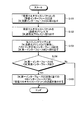
- FIG. 8 is a flowchart illustrating the processing operation of the relay device according to the first embodiment.
- FIG. 9 is a diagram for explaining route reorganization processing when a failure occurs.
- FIG. 10 is a diagram for explaining route reorganization processing when a failure occurs.
- FIG. 11 is a diagram for explaining the prior art.
- FIG. 12 is a diagram for explaining the prior art.
- FIG. 1 is a block diagram illustrating the configuration of the relay device according to the first embodiment.
- FIG. 2 is a diagram for explaining a data configuration example of a multicast packet.
- FIG. 3 is a diagram illustrating a configuration example of the routing table. 4 to 7 are diagrams for explaining the multicast packet transmission processing.
- the relay device 10 includes an input / output control unit 11, a communication interface 12, a communication control unit 13, a storage unit 14, and a control unit 15, and includes a key station 20 and a viewer terminal 30 via a network. , Connected to other relay devices. The processing of each of these units will be described below.
- the input / output control unit 11 controls an input operation and a display operation for performing static routing definition, communication interface implementation definition, and the like.
- the communication interface 12 communicates with the adjacent key station 20, the viewer terminal 30, and other relay devices (hereinafter referred to as adjacent devices).
- the communication control unit 13 controls the communication interface 12 and controls transmission / reception of multicast packets with neighboring devices.
- the data structure of the multicast packet will be described with reference to FIG.
- the multicast packet has a “source address” that is the address of the source key station of the multicast packet and a “destination address” that is the multicast address.
- the storage unit 14 stores data and programs necessary for various processes performed by the control unit 15, and particularly stores a routing table 14a.
- the routing table 14a stores a routing table in which a destination address of a unicast packet is associated with a transmission interface that is a routing destination interface of the unicast packet.
- the routing table 14 a includes a “destination network address” that is destination network address range information when a unicast packet is transmitted, and a unicast toward the destination network address range.
- An “interface ID” which is an identifier of a packet transmission interface used when transmitting a packet is stored in association with each other.
- the control unit 15 has an internal memory for storing a program that defines various processing procedures and the necessary data, and executes various processes, and in particular, a packet extraction unit 15a, an interface extraction unit 15b, An interface determination unit 15c and a packet transmission control unit 15d are provided.
- the packet extraction unit 15a specifies the reception interface that has received the multicast packet and extracts the source address from the multicast packet.
- the packet extraction unit 15a identifies the reception interface that has received the multicast packet, and extracts the interface ID of the identified interface as “W_reception interface ID”. Then, the packet extraction unit 15a extracts the source address included in the multicast packet and extracts it to “W_source address”.
- the interface extraction unit 15b searches the routing table 14a for the destination address of the unicast packet corresponding to the source address included in the multicast packet, and extracts the transmission interface corresponding to the searched destination address from the routing table 14a.
- the interface extraction unit 15b searches the routing table 14a for a destination network address that matches the “W_source address” extracted by the packet extraction unit 15a. Then, the interface extraction unit 15b extracts the searched destination network address to “W_first interface ID”.
- the interface determination unit 15c determines whether the identified reception interface matches the extracted transmission interface. Specifically, the interface determination unit 15c determines whether the “W_reception interface ID” extracted by the packet extraction unit 15a matches the “W_first interface ID” extracted by the interface extraction unit 15b. judge.
- the interface determination unit 15c notifies the packet transmission control unit 15d described later of a request for multicasting. Also, the interface determination unit 15c discards the multicast packet when “W_reception interface ID” and “W_first interface ID” do not match.
- the packet transmission control unit 15d performs control so as to transmit a multicast packet to all interfaces except the reception interface when it is determined that the reception interface and the transmission interface match.
- the packet transmission control unit 15d when the packet transmission control unit 15d receives a request for multicasting from the interface determination unit 15c, the packet transmission control unit 15d transmits the multicast packet to all communication interfaces except “W_first interface ID”. To control.
- the multicast packet is relayed to the downstream interface (other than the upstream interface) only when the multicast packet is received from the upstream interface (the routing destination interface when sending the unicast packet toward the source address of the multicast packet).
- a dotted line with “arrow or circle” is a flow of one multicast packet transmitted from the key station #A.
- a dotted line with an arrow indicates that the device that has received the multicast packet on the arrow end side relays the multicast packet to the adjacent device.
- a dotted line with a circle indicates that the device at the end of the circle does not relay a multicast packet to an adjacent device.
- a solid line with an arrow indicates a first interface to the key station #A (interface direction in which a unicast packet addressed to the key station #A is transmitted) as seen from a device connected in the opposite direction of the arrow. Represents.
- the key station #A transmits a multicast packet to the relay apparatus #A.
- the relay apparatus #A extracts the “source address” from the multicast packet.
- the relay device #A extracts the interface ID corresponding to the “destination network address” that matches the extracted source address from the routing table 14a. Subsequently, the relay apparatus #A determines whether or not the extracted interface ID matches the ID of the interface that has received the multicast packet.
- the extracted interface ID matches the ID of the interface that has received the multicast packet (hereinafter referred to as “reception from the first interface”).
- the packet is multicast to the relay devices #B and #C and the viewer terminal #A.
- the relay device #B when the relay device #B receives the multicast packet from the relay device #A, the relay device #B performs a determination process similar to the above to determine “reception from the first interface”, and transmits the multicast packet to the relay devices #C and #. Multicast to D.
- the relay device #C when the relay device #C receives the multicast packet from the relay device #A, the relay device #C performs a determination process similar to the above to determine “reception from the first interface”, and determines the multicast packet as the relay device #B, #. Multicast to D and #F.
- the relay device #B when the relay device #B receives the multicast packet from the relay device #C, the relay device #B performs a determination process similar to the above to determine “reception from other than the first interface”, and performs the multicast packet without performing the multicast. Throw away.
- the relay device #C when the relay device #C receives the multicast packet from the relay device #B, the relay device #C performs a determination process similar to the above to determine “reception from other than the first interface”, and performs the multicast packet without performing the multicast. Throw away.
- the relay device #D when the relay device #D receives the multicast packet from the relay device #B, the relay device #D performs a determination process similar to the above to determine “reception from the first interface”, and determines the multicast packet as the relay device #C, # E, #G, viewer terminal #E, multicast to key station #B.
- the relay device #D when the relay device #D receives the multicast packet from the relay device #C, the relay device #D performs a determination process similar to the above to determine “reception from other than the first interface”, and performs the multicast packet without performing the multicast. throw away.
- the communication interface that received the multicast packet is excluded from the multicast packet. It is distributed to viewers by multicasting to neighboring devices via the communication interface.
- a dotted line with an “arrow or circle” in FIG. 5 is a flow of one multicast packet transmitted from the key station #B.
- a blue solid line with an arrow indicates a first interface to the key station #B (interface and direction in which a unicast packet addressed to the key station #A is transmitted) as seen from the device connected in the opposite direction of the arrow. .
- the meaning of “arrow or circle” is the same as in FIG.
- the key station #B transmits a multicast packet to the relay apparatus #D.
- the relay device #D receives the multicast packet from the key station #B, the relay device #D performs a determination process similar to the above to determine “reception from the first interface”, and transmits the multicast packet to the relay devices #B, #C, # E, #G, multicast to viewer terminal #E.
- the relay device #B when the relay device #B receives the multicast packet from the relay device #D, the relay device #B performs a determination process similar to the above to determine “reception from the first interface”, and transmits the multicast packet to the relay devices #A, #. Multicast to C.
- the relay device #C when the relay device #C receives the multicast packet from the relay device #D, the relay device #C performs a determination process similar to the above to determine “reception from the first interface”, and determines the multicast packet as the relay device #A, #. Multicast to B and #F.
- the relay device #B when the relay device #B receives the multicast packet from the relay device #C, the relay device #B performs a determination process similar to the above to determine “reception from other than the first interface”, and performs the multicast packet without performing the multicast. Throw away.
- the relay device #C when the relay device #C receives the multicast packet from the relay device #B, the relay device #C performs a determination process similar to the above to determine “reception from other than the first interface”, and performs the multicast packet without performing the multicast. Throw away.
- the relay device #A when the relay device #A receives the multicast packet from the relay device #B, the relay device #A performs a determination process similar to the above to determine “reception from the first interface”, and determines the multicast packet as the viewer terminal #A, Multicast to key station #A.
- the relay device #A when the relay device #A receives the multicast packet from the relay device #C, the relay device #A performs a determination process similar to the above to determine “reception from other than the first interface”, and performs the multicast packet without performing the multicast. throw away.
- the communication interface that received the multicast packet is excluded from the multicast packet. It is distributed to viewers by multicasting to neighboring devices via the communication interface.
- each relay device for the multicast packet from the key station #A described in FIG. 4 and the distribution processing of each relay device for the multicast packet even transmitted from the key station #B described in FIG.
- a forwarding path for multicast packets from the key stations #A and #B is formed.
- the relay apparatus 10 As shown in FIG. 7, the relay apparatus 10 according to the first embodiment is applied to a multicast transmission system having a router that transmits a multicast packet by limiting the number of packet relays by TTL (Time To Live). May be.
- TTL Time To Live
- FIG. 8 is a flowchart illustrating the processing operation of the relay device 10 according to the first embodiment.
- the relay device 10 identifies the reception interface that has received the multicast packet, and extracts the interface ID of the identified interface as “W_reception interface ID” (step S101). Then, the packet extraction unit 15a extracts the transmission source address included in the received multicast and extracts it to “W_transmission source address” (step S102).
- the relay device 10 searches the routing table 14a for a destination network address that matches “W_source address”. Then, the relay device 10 extracts the searched destination network address to “W_first interface ID” (step S103).
- the relay device 10 determines whether “W_reception interface ID” and “W_first interface ID” match (step S104). As a result, when the “W_reception interface ID” and the “W_first interface ID” match (Yes in step S104), the relay device 10 determines all communication interfaces except “W_first interface ID”. Then, control is performed to transmit a multicast packet (step S105).
- the relay device 10 discards the multicast packet and ends the process.
- the relay device 10 stores the routing table 14a in which the destination address of the unicast packet is associated with the transmission interface that is a routing destination interface when sending to the destination address. Then, when receiving the multicast packet, the relay device 10 specifies the reception interface that has received the multicast packet and extracts the transmission source address from the multicast packet. Subsequently, the relay device 10 searches the routing table 14a for a destination address corresponding to the extracted transmission source address, and extracts a transmission interface corresponding to the searched destination address from the routing table 14a. Thereafter, the relay device 10 determines whether the identified reception interface matches the extracted transmission interface, and when it is determined that the reception interface matches the transmission interface, the relay device 10 multicasts the multicast packet. Control. For this reason, the relay apparatus 10 can expand the distribution range of the multicast packet while reducing the network traffic load due to the multicast packet without increasing the transmission delay.
- the routing table stores the routing table 14a in which the destination address of the unicast packet is associated with the transmission interface that is the routing destination interface of the unicast packet. Therefore, the multicast packet can be relayed only when the multicast packet is received from the upstream interface (the routing destination interface in the case of sending the unicast packet toward the source address of the multicast packet).
- the multicast packet when it is determined that the “W_reception interface ID” and the “W_first interface ID” match, the multicast packet is transmitted to all the interfaces except the “W_first interface ID”. Since control is performed so as to perform multicasting, it is possible to further reduce the traffic load on the network due to multicast packets.
- FIG. 9 and 10 are diagrams for explaining the route reorganization processing when a failure occurs.
- a known route change mechanism such as RIP (routing information protocol) or OSPF (Open Shortest Path First).
- OSPF Open Shortest Path First
- the route is changed.
- the transmission interface of the unicast packet destined for the key station #B is changed from “connection interface with the relay device #D” to “relay device #C” according to the route change due to the link failure. Is switched to the “connection interface” and the routing table 14a is updated.
- relay device #D the transmission interface for unicast packets destined for key station #A is changed from “connection interface with relay device #B” to “connection interface with relay device #C” in response to a route change due to a link failure. To update the routing table 14a.
- the key station #A transmits a unicast packet to the relay device #A
- the unicast packet passes from the relay device #A to the relay device #C and then reaches the relay device #D. Then, as in the first embodiment, when the relay apparatus #D receives the multicast packet, the relay apparatus #D extracts the “source address” from the multicast packet.
- the relay apparatus #D extracts the interface ID corresponding to the “destination network address” that matches the extracted source address from the routing table 14a. Subsequently, the relay device #D determines whether the extracted interface ID matches the ID of the interface that has received the multicast packet.
- the extracted interface ID matches the ID of the interface that has received the multicast packet (hereinafter referred to as “reception from the first interface”).
- the packet is multicast to the relay devices #B, #E, #G and the viewer terminal #E.
- the key station #B transmits a unicast packet to the relay apparatus #D
- the unicast packet reaches the relay apparatus #C from the relay apparatus #D.
- the relay device #C receives the multicast packet from the relay device #D
- the relay device #C performs a determination process similar to the above to determine “reception from the first interface”, and determines the multicast packet as the relay device #B, #A, #. Multicast to F.
- the relay device #B when the relay device #B receives the multicast packet from the relay device #C, the relay device #B performs a determination process similar to the above to determine “reception from the first interface”, and determines the multicast packet as the relay device #A, #. Multicast to D.
- the relay device #A receives the multicast packet from the relay device #B, the relay device #A performs a determination process similar to the above to determine “reception from the first interface”, and determines the multicast packet as the viewer #A, the key station Multicast to #A.
- the relay device #A when the relay device #A receives the multicast packet from the relay device #C, the relay device #A performs a determination process similar to the above to determine “reception from other than the first interface”, and performs the multicast packet without performing the multicast. throw away.
- FIG. 10 will be described.
- a link failure occurs between the relay device #B and the relay device #D, and the path is changed, and transmission of the relay devices #B and #D is performed.
- the transmission interface of the relay device #A is switched.
- the transmission interface of the unicast packet toward the key station #B is “relay device #” in response to the path change due to the link failure.
- the routing table 14a is updated by switching from “connection interface with B” to “connection interface with relay device #C”.
- the relay device #A when the relay device #A receives the multicast packet transmitted from the key station #B from the relay device #C, the relay device #A performs a determination process similar to the above to determine “reception from the first interface”.
- the multicast packet is multicast to the viewer #A and the key station #A.
- the relay device #A when the relay device #A receives the multicast packet transmitted from the key station #B from the relay device #B, the relay device #A performs a determination process similar to the above to determine “reception from other than the first interface” and performs the multicast. Without doing so, discard the multicast packet.
- the routing table is updated according to the failure of the distribution route. It is possible to relay.
- each component of each illustrated device is functionally conceptual and does not necessarily need to be physically configured as illustrated.
- the specific form of distribution / integration of each device is not limited to that shown in the figure, and all or a part thereof may be functionally or physically distributed or arbitrarily distributed in arbitrary units according to various loads or usage conditions. Can be integrated and configured.
- the packet extraction unit 15a and the interface extraction unit 15b may be integrated.
- all or any part of each processing function performed in each device may be realized by a CPU and a program analyzed and executed by the CPU, or may be realized as hardware by wired logic.
- the multicast packet relay method described in this embodiment can be realized by executing a program prepared in advance on a computer such as a personal computer or a workstation.
- This program can be distributed via a network such as the Internet.
- the program can also be executed by being recorded on a computer-readable recording medium such as a hard disk, a flexible disk (FD), a CD-ROM, an MO, and a DVD and being read from the recording medium by the computer.
- a computer-readable recording medium such as a hard disk, a flexible disk (FD), a CD-ROM, an MO, and a DVD and being read from the recording medium by the computer.
Landscapes
- Engineering & Computer Science (AREA)
- Computer Networks & Wireless Communication (AREA)
- Signal Processing (AREA)
- Data Exchanges In Wide-Area Networks (AREA)
Abstract
中継装置(10)は、マルチキャストパケットを受信した場合に、マルチキャストパケットを受信した受信インターフェースを特定するとともに、マルチキャストパケットから送信元アドレスを抽出する。続いて、中継装置(10)は、抽出された送信元アドレスに該当するユニキャストパケットのあて先アドレスをルーティングテーブル(14a)から検索し、検索されたユニキャストパケットのあて先アドレスに対応する送信インターフェースをルーティングテーブル(14a)から抽出する。その後、中継装置(10)は、特定された受信インターフェースと、抽出された送信インターフェースとが一致するか判定し、受信インターフェースと送信インターフェースとが一致すると判定された場合には、マルチキャストパケットをマルチキャストするように制御する。
Description
近年、インターネットなどのネットワークを介して、複数の端末装置からの視聴リクエストに応じて、コンテンツ配信装置から端末装置へと、コンテンツを配信するIPTV(Internet Protocol Television)放送が知られている。
IPTV(Internet Protocol Television)放送のようなコンテンツを配信において、コンテンツのマルチキャスト送信が実施されている。このようなマルチキャスト送信では、ルータ等の中継装置で複製された複数のインターフェースより送信される。
例えば、マルチキャスト送信の技術として、TTL(Time To Live)によりパケットの中継回数を制限して、マルチキャストパケットを送信する技術が知られている。具体的には、図11に例示するように、マルチキャストパケットを中継するルータ#A~#Gは、マルチキャストパケットを受信すると、マルチキャストパケット内のTTLを「1」減算する。
そして、ルータ#A~#Gは、減算を行った後のTTLが「0」でない場合には、マルチキャストを隣接装置全てに中継する。一方、ルータ#A~#Gは、減算を行った後のTTLが「0」である場合には、マルチキャストパケットを隣接装置へ中継しない。
また、マルチキャスト送信の技術として、ルータをグループ分けし、配信元ルータから配信先ルータグループを指定して、マルチキャストパケットを送信する技術も知られている(特許文献1参照)。具体的には、図12に例示するように、マルチキャストパケットの配信先ごとにルータグループを構成する。
このような構成のもと、1グループに対して1ビットを割り当てることで、キー局からのマルチキャストパケットをグループ毎のビット指定でルータ間を配信する。例えば、図12の例を用いて説明すると、ルータ#Aは、キー局#Aからマルチキャストパケットを受信すると、配信先グループ対応のビットを付与したパケットを送信する。
そして、配信先グループ対応のビットが付与されたパケットを受信したルータ#B,#Cは、ルータに予め設定されているグループ毎のルーチング先のインターフェースへ配信先グループ対応のビットを再編集して配信する。なお、配信先の増大によりグループ対応のビットが枯渇する場合があるため、ビットの枯渇への対応として、1グループを大きくしている。
ところで、上記したTTLによりパケットの中継回数を制限してマルチキャストパケットを送信する技術では、ルータがTTL「0」になるまで、受信したマルチキャストパケットを隣接装置全てに中継するので、ネットワークのトラヒック負荷(図11の例では、特にキー局#A近傍のトラヒック負荷)が増大するという課題があった。また、パケットの中継回数を制限しているので、マルチキャストパケットが適切に広範囲の視聴者端末に配信されず、マルチキャストパケットの配信範囲が狭いという課題があった。
また、上記した、ルータをグループ分けし、配信元ルータから配信先ルータグループを指定してマルチキャストパケットを送信する技術では、ビットの枯渇への対応として、1グループを大きくする。このため、ルータがパケットを受信した場合に、コピー配信先のインターフェース数が増大することとなる。また、個々のインターフェース毎にパケットイメージが異なるため、多大な送信用バッファを必要とする結果、コピー処理による送信遅延が増大するという課題があった。
そこで、この発明は、上述した従来技術の課題を解決するためになされたものであり、送信遅延が増大することなく、マルチキャストパケットによるネットワークのトラヒック負荷を低減しつつ、マルチキャストパケットの配信範囲を拡大することを目的とする。
上述した課題を解決し、目的を達成するため、この装置は、マルチキャストパケットを受信した受信インターフェースと、ルーティング先インターフェースである送信インターフェースとが一致する場合には、マルチキャストパケットをマルチキャストするように制御することを要件とする。
開示の装置は、送信遅延が増大することなく、マルチキャストパケットによるネットワークのトラヒック負荷を低減しつつ、マルチキャストパケットの配信範囲を拡大するという効果を奏する。
10 中継装置
11 入出力制御部
12 通信インターフェース
13 通信制御部
14 記憶部
14a ルーティングテーブル
15 制御部
15a パケット抽出部
15b インターフェース抽出部
15c インターフェース判定部
15d パケット送信制御部
11 入出力制御部
12 通信インターフェース
13 通信制御部
14 記憶部
14a ルーティングテーブル
15 制御部
15a パケット抽出部
15b インターフェース抽出部
15c インターフェース判定部
15d パケット送信制御部
以下に添付図面を参照して、この発明に係る中継装置、中継方法および中継プログラムの実施例を詳細に説明する。
以下の実施例では、実施例1に係る中継装置の構成および処理の流れを順に説明し、最後に実施例1による効果を説明する。なお、以下では、TV放送コンテンツを送信するキー局から視聴者が視聴する視聴者端末へ送信されるマルチキャストパケットに本発明を適用する場合の例を説明する。
[中継装置の構成]
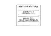
まず最初に、図1~図7を用いて、実施例1に係る中継装置10の構成を説明する。図1は、実施例1に係る中継装置の構成を示すブロック図である。図2は、マルチキャストパケットのデータ構成例を説明するための図である。図3は、ルーティングテーブルの構成例を示す図である。図4~図7は、マルチキャストパケットの送信処理を説明するための図である。
まず最初に、図1~図7を用いて、実施例1に係る中継装置10の構成を説明する。図1は、実施例1に係る中継装置の構成を示すブロック図である。図2は、マルチキャストパケットのデータ構成例を説明するための図である。図3は、ルーティングテーブルの構成例を示す図である。図4~図7は、マルチキャストパケットの送信処理を説明するための図である。
図1に示すように、この中継装置10は、入出力制御部11、通信インターフェース12、通信制御部13、記憶部14、制御部15を備え、ネットワークを介してキー局20、視聴者端末30、他の中継装置と接続される。以下にこれらの各部の処理を説明する。
入出力制御部11は、スタティックなルーティング定義や、通信インターフェースの実装定義などを行うための入力操作および表示操作を制御する。通信インターフェース12は、隣接するキー局20、視聴者端末30、他の中継装置(以下、隣接装置という)との間で通信を行う。
通信制御部13は、通信インターフェース12を制御し、隣接装置とのマルチキャストパケットの送受信を制御する。ここで、マルチキャストパケットのデータ構成について図2を用いて説明する。同図に示すように、マルチキャストパケットは、マルチキャストパケットの送信元キー局のアドレスである「送信元アドレス」、マルチキャスト用アドレスである「あて先アドレス」を有している。
記憶部14は、制御部15による各種処理に必要なデータおよびプログラムを格納するが、特に、ルーティングテーブル14aを記憶する。
ルーティングテーブル14aは、ユニキャストパケットのあて先アドレスと、ユニキャストパケットのルーティング先インターフェースである送信インターフェースとが対応付けられたルーティングテーブルを記憶する。
具体的には、ルーティングテーブル14aは、図3に例示するように、ユニキャストパケットを送信する場合のあて先ネットワークアドレスの範囲情報である「あて先ネットワークアドレス」と、あて先ネットワークアドレスの範囲に向けユニキャストパケットを送信する場合に利用するパケット送信用インターフェースの識別子である「インターフェースID」とを対応付けて記憶する。
制御部15は、各種の処理手順などを規定したプログラムおよび所要データを格納するための内部メモリを有し、これらによって種々の処理を実行するが、特に、パケット抽出部15a、インターフェース抽出部15b、インターフェース判定部15c、パケット送信制御部15dを備える。
パケット抽出部15aは、マルチキャストパケットを受信した場合に、マルチキャストパケットを受信した受信インターフェースを特定するとともに、マルチキャストパケットから送信元アドレスを抽出する。
具体的には、パケット抽出部15aは、マルチキャストパケットを受信した受信インターフェースを特定し、特定されたインターフェースのインターフェースIDを「W_受信インターフェースID」に取り出す。そして、パケット抽出部15aは、マルチキャストパケットに含まれる送信元アドレスを抽出し、「W_送信元アドレス」へ取り出す。
インターフェース抽出部15bは、マルチキャストパケットに含まれた送信元アドレスに該当するユニキャストパケットのあて先アドレスをルーティングテーブル14aから検索し、検索されたあて先アドレスに対応する送信インターフェースをルーティングテーブル14aから抽出する。
具体的には、インターフェース抽出部15bは、パケット抽出部15aによって取り出された「W_送信元アドレス」にマッチするあて先ネットワークアドレスをルーティングテーブル14aから検索する。そして、インターフェース抽出部15bは、検索されたあて先ネットワークアドレスを「W_第一インターフェースID」へ取り出す。
インターフェース判定部15cは、特定された受信インターフェースと、抽出された送信インターフェースとが一致するか判定する。具体的には、インターフェース判定部15cは、パケット抽出部15aによって取り出された「W_受信インターフェースID」と、インターフェース抽出部15bによって取り出された「W_第一インターフェースID」とが一致するか否かを判定する。
この結果、インターフェース判定部15cは、「W_受信インターフェースID」と「W_第一インターフェースID」とが一致する場合には、マルチキャストする旨の要求を後述するパケット送信制御部15dに通知する。また、インターフェース判定部15cは、「W_受信インターフェースID」と「W_第一インターフェースID」とが一致しない場合には、マルチキャストパケットを捨てる。
パケット送信制御部15dは、受信インターフェースと送信インターフェースとが一致すると判定された場合には、受信インターフェースを除く全てのインターフェースへマルチキャストパケットを送信するように制御する。
具体的には、パケット送信制御部15dは、インターフェース判定部15cからマルチキャストする旨の要求を受け付けた場合には、「W_第一インターフェースID」を除く全ての通信インターフェースに対し、マルチキャストパケットを送信するように制御する。
つまり、マルチキャストパケットを上流インターフェース(マルチキャストパケットの送信元アドレスへ向け、ユニキャストパケットを送る場合のルーティング先インターフェース)から受信した場合に限り、下流インターフェース(上流インターフェース以外)へマルチキャストパケットを中継する。
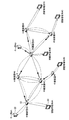
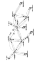
ここで、マルチキャストパケットの送信処理について図4~図6の例を用いて具体的に説明する。図4では、「矢印または丸印」付の点線は、キー局#Aから送信された1つのマルチキャストパケットの流れである。この図4の例では、矢印付の点線は、矢印端側のマルチキャストパケット受信した装置が、隣接装置へマルチキャストパケットを中継することを表している。また、丸印付の点線は、丸印端側の装置が、隣接装置へマルチキャストパケットを中継しないことを表している。
また、図4では、矢印付の実線は、矢印の反対に接続された装置からみて、キー局#Aへの第一のインターフェース(キー局#A宛のユニキャストパケットが送信されるインターフェース方向)を表している。
同図に示すように、キー局#Aが中継装置#Aへマルチキャストパケットを送信する。中継装置#Aは、マルチキャストパケットを受信すると、マルチキャストパケットから「送信元アドレス」を抽出する。
そして、中継装置#Aは、抽出された送信元アドレスと一致する「あて先ネットワークアドレス」に対応するインターフェースIDをルーティングテーブル14aから抽出する。続いて、中継装置#Aは、抽出されたインターフェースIDと、マルチキャストパケットを受信したインターフェースのIDとが一致するか判定する。
図4の例では、抽出されたインターフェースIDと、マルチキャストパケットを受信したインターフェースのIDとが一致する(以後、「第一インターフェースからの受信」と記載)と判定し、中継装置#Aは、マルチキャストパケットを中継装置#B、#Cおよび視聴者端末#Aへマルチキャストする。
次に、中継装置#Bは、中継装置#Aからマルチキャストパケットを受信すると、上記と同様の判定処理を行って「第一インターフェースからの受信」と判定し、マルチキャストパケットを中継装置#C、#Dへマルチキャストする。
同様に、中継装置#Cは、中継装置#Aからマルチキャストパケットを受信すると、上記と同様の判定処理を行って「第一インターフェースからの受信」と判定し、マルチキャストパケットを中継装置#B、#D、#Fへマルチキャストする。
続いて、中継装置#Bは、中継装置#Cからマルチキャストパケットを受信すると、上記と同様の判定処理を行って「第一インターフェース以外からの受信」と判定し、マルチキャストを行わずに、マルチキャストパケットを捨てる。
同様に、中継装置#Cは、中継装置#Bからマルチキャストパケットを受信すると、上記と同様の判定処理を行って「第一インターフェース以外からの受信」と判定し、マルチキャストを行わずに、マルチキャストパケットを捨てる。
続いて、中継装置#Dは、中継装置#Bからマルチキャストパケットを受信すると、上記と同様の判定処理を行って「第一インターフェースからの受信」と判定し、マルチキャストパケットを中継装置#C、#E、#G、視聴者端末#E、キー局#Bへマルチキャストする。
一方、中継装置#Dは、中継装置#Cからマルチキャストパケットを受信すると、上記と同様の判定処理を行って「第一インターフェース以外からの受信」と判定し、マルチキャストを行わずに、マルチキャストパケットを捨てる。
また、中継装置#E、#F、#Gにおいても、マルチキャストパケットの受信が、「第一インターフェースからの受信」であると判定した場合のみ、マルチキャストパケットをそのマルチキャストパケットを受信した通信インターフェースを除く通信インターフェースにて、隣接装置へマルチキャストすることで、視聴者へ向け配信する。
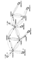
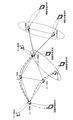
次に、図5を用いてマルチキャストパケットの送信処理について説明する。図5の「矢印または丸印」付の点線は、キー局#Bから送信された1つのマルチキャストパケットの流れである。矢印付青の実線は、矢印の反対に接続された装置からみて、キー局#Bへの第一のインターフェース(キー局#A宛のユニキャストパケットが送信されるインターフェースと方向)を表している。また、「矢印または丸印」の意味は、図4と同様である。
同図に示すように、キー局#Bが中継装置#Dへマルチキャストパケットを送信する。中継装置#Dは、キー局#Bからマルチキャストパケットを受信すると、上記と同様の判定処理を行って「第一インターフェースからの受信」と判定し、マルチキャストパケットを中継装置#B、#C、#E、#G、視聴者端末#Eへマルチキャストする。
次に、中継装置#Bは、中継装置#Dからマルチキャストパケットを受信すると、上記と同様の判定処理を行って「第一インターフェースからの受信」と判定し、マルチキャストパケットを中継装置#A、#Cへマルチキャストする。
同様に、中継装置#Cは、中継装置#Dからマルチキャストパケットを受信すると、上記と同様の判定処理を行って「第一インターフェースからの受信」と判定し、マルチキャストパケットを中継装置#A、#B、#Fへマルチキャストする。
続いて、中継装置#Bは、中継装置#Cからマルチキャストパケットを受信すると、上記と同様の判定処理を行って「第一インターフェース以外からの受信」と判定し、マルチキャストを行わずに、マルチキャストパケットを捨てる。
同様に、中継装置#Cは、中継装置#Bからマルチキャストパケットを受信すると、上記と同様の判定処理を行って「第一インターフェース以外からの受信」と判定し、マルチキャストを行わずに、マルチキャストパケットを捨てる。
続いて、中継装置#Aは、中継装置#Bからマルチキャストパケットを受信すると、上記と同様の判定処理を行って「第一インターフェースからの受信」と判定し、マルチキャストパケットを視聴者端末#A、キー局#Aへマルチキャストする。
一方、中継装置#Aは、中継装置#Cからマルチキャストパケットを受信すると、上記と同様の判定処理を行って「第一インターフェース以外からの受信」と判定し、マルチキャストを行わずに、マルチキャストパケットを捨てる。
また、中継装置#E、#F、#Gにおいても、マルチキャストパケットの受信が、「第一インターフェースからの受信」であると判定した場合のみ、マルチキャストパケットをそのマルチキャストパケットを受信した通信インターフェースを除く通信インターフェースにて、隣接装置へマルチキャストすることで、視聴者へ向け配信する。
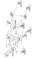
このように、図4で説明したキー局#Aからのマルチキャストパケットに対する各中継装置の配信処理と、図5で説明したキー局#Bから送信さえたマルチキャストパケットに対する各中継装置の配信処理とをまとめると、図6に示すように、キー局#A、#Bからのマルチキャストパケットの転送経路が形成される。
なお、図7に示すように、TTL(Time To Live)によりパケットの中継回数を制限してマルチキャストパケットを送信するルータを有するマルチキャスト送信システムに、実施例1に係る中継装置10を適用するようにしてもよい。
[中継装置による処理]
次に、図8を用いて、実施例1に係る中継装置10による処理を説明する。図8は、実施例1に係る中継装置10の処理動作を示すフローチャートである。
次に、図8を用いて、実施例1に係る中継装置10による処理を説明する。図8は、実施例1に係る中継装置10の処理動作を示すフローチャートである。
同図に示すように、中継装置10は、マルチキャストパケットを受信した受信インターフェースを特定し、特定されたインターフェースのインターフェースIDを「W_受信インターフェースID」に取り出す(ステップS101)。そして、パケット抽出部15aは、受信したマルチキャストに含まれる送信元アドレスを抽出し、「W_送信元アドレス」へ取り出す(ステップS102)。
そして、中継装置10は、「W_送信元アドレス」にマッチするあて先ネットワークアドレスをルーティングテーブル14aから検索する。そして、中継装置10は、検索されたあて先ネットワークアドレスを「W_第一インターフェースID」へ取り出す(ステップS103)。
また、中継装置10は、「W_受信インターフェースID」と、「W_第一インターフェースID」とが一致するか否かを判定する(ステップS104)。この結果、中継装置10は、「W_受信インターフェースID」と「W_第一インターフェースID」とが一致する場合には(ステップS104肯定)、「W_第一インターフェースID」を除く全ての通信インターフェースに対し、マルチキャストパケットを送信するように制御する(ステップS105)。
また、中継装置10は、「W_受信インターフェースID」と「W_第一インターフェースID」とが一致しない場合には(ステップS104否定)、マルチキャストパケットを捨てて処理を終了する。
[実施例1の効果]
上述してきたように、中継装置10は、ユニキャストパケットのあて先アドレスと、当該あて先アドレスに送る場合のルーティング先インターフェースである送信インターフェースとが対応付けられたルーティングテーブル14aを記憶する。そして、中継装置10は、マルチキャストパケットを受信した場合に、マルチキャストパケットを受信した受信インターフェースを特定するとともに、マルチキャストパケットから送信元アドレスを抽出する。続いて、中継装置10は、抽出された送信元アドレスに該当するあて先アドレスをルーティングテーブル14aから検索し、検索されたあて先アドレスに対応する送信インターフェースをルーティングテーブル14aから抽出する。その後、中継装置10は、特定された受信インターフェースと、抽出された送信インターフェースとが一致するか判定し、受信インターフェースと送信インターフェースとが一致すると判定された場合には、マルチキャストパケットをマルチキャストするように制御する。このため、中継装置10は、送信遅延が増大することなく、マルチキャストパケットによるネットワークのトラヒック負荷を低減しつつ、マルチキャストパケットの配信範囲を拡大することが可能である。
上述してきたように、中継装置10は、ユニキャストパケットのあて先アドレスと、当該あて先アドレスに送る場合のルーティング先インターフェースである送信インターフェースとが対応付けられたルーティングテーブル14aを記憶する。そして、中継装置10は、マルチキャストパケットを受信した場合に、マルチキャストパケットを受信した受信インターフェースを特定するとともに、マルチキャストパケットから送信元アドレスを抽出する。続いて、中継装置10は、抽出された送信元アドレスに該当するあて先アドレスをルーティングテーブル14aから検索し、検索されたあて先アドレスに対応する送信インターフェースをルーティングテーブル14aから抽出する。その後、中継装置10は、特定された受信インターフェースと、抽出された送信インターフェースとが一致するか判定し、受信インターフェースと送信インターフェースとが一致すると判定された場合には、マルチキャストパケットをマルチキャストするように制御する。このため、中継装置10は、送信遅延が増大することなく、マルチキャストパケットによるネットワークのトラヒック負荷を低減しつつ、マルチキャストパケットの配信範囲を拡大することが可能である。
また、実施例1によれば、ルーティングテーブルは、ユニキャストパケットのあて先アドレスと、ユニキャストパケットのルーティング先インターフェースである送信インターフェースとが対応付けられたルーティングテーブル14aを記憶する。このため、マルチキャストパケットを上流インターフェース(マルチキャストパケットの送信元アドレスへ向け、ユニキャストパケットを送る場合のルーティング先インターフェース)から受信した場合に限り、マルチキャストパケットを中継することが可能である。
また、実施例1によれば、「W_受信インターフェースID」と「W_第一インターフェースID」とが一致すると判定された場合には、「W_第一インターフェースID」を除く全てのインターフェースへマルチキャストパケットをマルチキャストするように制御するので、マルチキャストパケットによるネットワークのトラヒック負荷をさらに低減することが可能である。
ところで、マルチキャストパケットの配信経路を構成した後に、ネットワークに障害が発生した場合には、マルチキャストパケットの配信経路を再構成するようにしてもよい。そこで、以下の実施例2では、ネットワーク障害が発生した場合に、マルチキャストパケットの配信経路を再構成する場合として、図9および図10を用いて、実施例2における中継装置10aの処理について説明する。図9および図10は、障害発生時の経路再編処理を説明するための図である。
図9に例示するように、例えば、中継装置#Bと中継装置#Dとの間にリンク障害が発生すると、RIP(routing information protocol)やOSPF(Open Shortest Path First)等の既知の経路変更機構により、経路が変更となる。このような場合に、中継装置#Bでは、リンク障害による経路変更に応じて、キー局#Bへ向かうユニキャストパケットの送信インターフェースが「中継装置#Dとの接続インターフェース」から「中継装置#Cとの接続インターフェース」へ切り替えてルーティングテーブル14aを更新する。
また、中継装置#Dでは、リンク障害による経路変更に応じて、キー局#Aへ向かうユニキャストパケットの送信インターフェースが「中継装置#Bとの接続インターフェース」から「中継装置#Cとの接続インターフェース」へ切り替えてルーティングテーブル14aを更新する。
そして、キー局#Aが中継装置#Aにユニキャストパケットを送信した場合には、中継装置#Aから中継装置#Cへユニキャストパケットが経由した後、中継装置#Dへ届く。そして、中継装置#Dは、実施例1と同様に、マルチキャストパケットを受信すると、マルチキャストパケットから「送信元アドレス」を抽出する。
そして、中継装置#Dは、抽出された送信元アドレスと一致する「あて先ネットワークアドレス」に対応するインターフェースIDをルーティングテーブル14aから抽出する。続いて、中継装置#Dは、抽出されたインターフェースIDと、マルチキャストパケットを受信したインターフェースのIDとが一致するか判定する。
図9の例では、抽出されたインターフェースIDと、マルチキャストパケットを受信したインターフェースのIDとが一致する(以後、「第一インターフェースからの受信」と記載)と判定し、中継装置#Dは、マルチキャストパケットを中継装置#B、#E、#Gおよび視聴者端末#Eへマルチキャストする。
また、キー局#Bが中継装置#Dにユニキャストパケットを送信した場合には、中継装置#Dから中継装置#Cへユニキャストパケットが届く。中継装置#Cは、中継装置#Dからマルチキャストパケットを受信すると、上記と同様の判定処理を行って「第一インターフェースからの受信」と判定し、マルチキャストパケットを中継装置#B、#A、#Fへマルチキャストする。
続いて、中継装置#Bは、中継装置#Cからマルチキャストパケットを受信すると、上記と同様の判定処理を行って「第一インターフェースからの受信」と判定し、マルチキャストパケットを中継装置#A、#Dへマルチキャストする。
そして、中継装置#Aは、中継装置#Bからマルチキャストパケットを受信すると、上記と同様の判定処理を行って「第一インターフェースからの受信」と判定し、マルチキャストパケットを視聴者#A、キー局#Aへマルチキャストする。
一方、中継装置#Aは、中継装置#Cからマルチキャストパケットを受信すると、上記と同様の判定処理を行って「第一インターフェース以外からの受信」と判定し、マルチキャストを行わずに、マルチキャストパケットを捨てる。
また、図10の例について説明する。図10の例では、図9の例と同様に、中継装置#Bと中継装置#Dとの間にリンク障害が発生して経路が変更とる場合であり、中継装置#B、#Dの送信インターフェースが切り替わるとともに、中継装置#Aの送信インターフェースが切り替わる。具体的には、図10の例では、図9の例と異なり、中継装置#Aでは、リンク障害による経路変更に応じて、キー局#Bへ向かうユニキャストパケットの送信インターフェースが「中継装置#Bとの接続インターフェース」から「中継装置#Cとの接続インターフェース」へ切り替えてルーティングテーブル14aを更新する。
このような場合に、中継装置#Aは、キー局#Bが送信したマルチキャストパケットを中継装置#Cから受信すると、上記と同様の判定処理を行って「第一インターフェースからの受信」と判定し、マルチキャストパケットを視聴者#A、キー局#Aへマルチキャストする。
一方、中継装置#Aは、キー局#Bが送信したマルチキャストパケットを中継装置#Bから受信すると、上記と同様の判定処理を行って「第一インターフェース以外からの受信」と判定し、マルチキャストを行わずに、マルチキャストパケットを捨てる。
このように、上記の実施例2では、マルチキャストパケットの配信経路に障害が発生した場合には、配信経路の障害に応じて、前記ルーティングテーブルを更新するので、障害発生時にも適切にマルチキャストパケットを中継することが可能である。
さて、これまで本発明の実施例について説明したが、本発明は上述した実施例以外にも、種々の異なる形態にて実施されてよいものである。そこで、以下では実施例3として本発明に含まれる他の実施例を説明する。
(1)システム構成等
図示した各装置の各構成要素は機能概念的なものであり、必ずしも物理的に図示の如く構成されていることを要しない。すなわち、各装置の分散・統合の具体的形態は図示のものに限られず、その全部または一部を、各種の負荷や使用状況などに応じて、任意の単位で機能的または物理的に分散・統合して構成することができる。例えば、パケット抽出部15aとインターフェース抽出部15bを統合してもよい。さらに、各装置にて行なわれる各処理機能は、その全部または任意の一部が、CPUおよび当該CPUにて解析実行されるプログラムにて実現され、あるいは、ワイヤードロジックによるハードウェアとして実現され得る。
図示した各装置の各構成要素は機能概念的なものであり、必ずしも物理的に図示の如く構成されていることを要しない。すなわち、各装置の分散・統合の具体的形態は図示のものに限られず、その全部または一部を、各種の負荷や使用状況などに応じて、任意の単位で機能的または物理的に分散・統合して構成することができる。例えば、パケット抽出部15aとインターフェース抽出部15bを統合してもよい。さらに、各装置にて行なわれる各処理機能は、その全部または任意の一部が、CPUおよび当該CPUにて解析実行されるプログラムにて実現され、あるいは、ワイヤードロジックによるハードウェアとして実現され得る。
また、本実施例において説明した各処理のうち、自動的におこなわれるものとして説明した処理の全部または一部を手動的におこなうこともでき、あるいは、手動的におこなわれるものとして説明した処理の全部または一部を公知の方法で自動的におこなうこともできる。この他、上記文書中や図面中で示した処理手順、制御手順、具体的名称、各種のデータやパラメータを含む情報については、特記する場合を除いて任意に変更することができる。
(2)プログラム
なお、本実施例で説明したマルチキャストパケット中継方法は、あらかじめ用意されたプログラムをパーソナルコンピュータやワークステーションなどのコンピュータで実行することによって実現することができる。このプログラムは、インターネットなどのネットワークを介して配布することができる。また、このプログラムは、ハードディスク、フレキシブルディスク(FD)、CD-ROM、MO、DVDなどのコンピュータで読み取り可能な記録媒体に記録され、コンピュータによって記録媒体から読み出されることによって実行することもできる。
なお、本実施例で説明したマルチキャストパケット中継方法は、あらかじめ用意されたプログラムをパーソナルコンピュータやワークステーションなどのコンピュータで実行することによって実現することができる。このプログラムは、インターネットなどのネットワークを介して配布することができる。また、このプログラムは、ハードディスク、フレキシブルディスク(FD)、CD-ROM、MO、DVDなどのコンピュータで読み取り可能な記録媒体に記録され、コンピュータによって記録媒体から読み出されることによって実行することもできる。
Claims (12)
- ユニキャストパケットのあて先アドレスと、当該あて先アドレスに送る場合のルーティング先インターフェースである送信インターフェースとが対応付けられたルーティングテーブルを記憶するルーティングテーブル記憶部と、
マルチキャストパケットを受信した場合に、当該マルチキャストパケットを受信した受信インターフェースを特定するとともに、前記マルチキャストパケットから送信元アドレスを抽出するパケット抽出部と、
前記パケット抽出部によって抽出された前記送信元アドレスに該当するあて先アドレスを前記ルーティングテーブルから検索し、検索された当該あて先アドレスに対応する送信インターフェースを前記ルーティングテーブルから抽出するインターフェース抽出部と、
前記パケット抽出部によって特定された前記受信インターフェースが、前記インターフェース抽出部によって抽出された前記送信インターフェースに該当するか判定するインターフェース判定部と、
前記インターフェース判定部によって前記受信インターフェースが前記送信インターフェースに該当すると判定された場合には、前記マルチキャストパケットをマルチキャストするように制御する送信制御部と、
を備えることを特徴とする中継装置。 - 前記ルーティングテーブルは、ユニキャストパケットのあて先アドレスと、当該ユニキャストパケットのルーティング先インターフェースである送信インターフェースとが対応付けられたルーティングテーブルを記憶することを特徴とする請求項1に記載の中継装置。
- 前記送信制御部は、前記インターフェース判定部によって前記受信インターフェースが前記送信インターフェースに該当すると判定された場合には、当該受信インターフェースを除く全てのインターフェースへマルチキャストパケットをマルチキャストするように制御することを特徴とする請求項1または2に記載の中継装置。
- 前記マルチキャストパケットの配信経路に障害が発生した場合には、当該配信経路の障害に応じて、前記ルーティングテーブルを更新するルーティングテーブル更新部をさらに備えることを特徴とする請求項1に記載の中継装置。
- マルチキャストパケットを受信した場合に、当該マルチキャストパケットを受信した受信インターフェースを特定するとともに、前記マルチキャストパケットから送信元アドレスを抽出するパケット抽出ステップと、
ユニキャストパケットのあて先アドレスと当該あて先アドレスに送る場合のルーティング先インターフェースである送信インターフェースとが対応付けられたルーティングテーブルから、前記パケット抽出ステップによって抽出された前記送信元アドレスに該当するあて先アドレスを検索し、検索された当該あて先アドレスに対応する送信インターフェースを前記ルーティングテーブルから抽出するインターフェース抽出ステップと、
前記パケット抽出ステップによって特定された前記受信インターフェースが、前記インターフェース抽出ステップによって抽出された前記送信インターフェースに該当するか判定するインターフェース判定ステップと、
前記インターフェース判定ステップによって前記受信インターフェースが前記送信インターフェースに該当すると判定された場合には、マルチキャストパケットをマルチキャストするように制御する送信制御ステップと、
を含んだことを特徴とする中継方法。 - 前記インターフェース抽出ステップは、ユニキャストパケットのあて先アドレスと、当該ユニキャストパケットのルーティング先インターフェースである送信インターフェースとが対応付けられたルーティングテーブルから、前記パケット抽出ステップによって抽出された前記送信元アドレスに該当するあて先アドレスを検索し、検索された当該あて先アドレスに対応する送信インターフェースを前記ルーティングテーブルから抽出することを特徴とする請求項5に記載の中継方法。
- 前記送信制御ステップは、前記インターフェース判定ステップによって前記受信インターフェースが前記送信インターフェースに該当すると判定された場合には、当該受信インターフェースを除く全てのインターフェースへマルチキャストパケットをマルチキャストするように制御することを特徴とする請求項5または6に記載の中継方法。
- 前記マルチキャストパケットの配信経路に障害が発生した場合には、当該配信経路の障害に応じて、前記ルーティングテーブルを更新するルーティングテーブル更新ステップをさらに含んだことを特徴とする請求項5に記載の中継方法。
- マルチキャストパケットを受信した場合に、当該マルチキャストパケットを受信した受信インターフェースを特定するとともに、前記マルチキャストパケットから送信元アドレスを抽出するパケット抽出手順と、
ユニキャストパケットのあて先アドレスと当該あて先アドレスに送る場合のルーティング先インターフェースである送信インターフェースとが対応付けられたルーティングテーブルから、前記パケット抽出手順によって抽出された前記送信元アドレスに該当するあて先アドレスを検索し、検索された当該あて先アドレスに対応する送信インターフェースを前記ルーティングテーブルから抽出するインターフェース抽出手順と、
前記パケット抽出手順によって特定された前記受信インターフェースが、前記インターフェース抽出手順によって抽出された前記送信インターフェースに該当するか判定するインターフェース判定手順と、
前記インターフェース判定手順によって前記受信インターフェースが前記送信インターフェースに該当すると判定された場合には、マルチキャストパケットをマルチキャストするように制御する送信制御手順と、
をコンピュータに実行させることを特徴とする中継プログラム。 - 前記インターフェース抽出手順は、ユニキャストパケットのあて先アドレスと、当該ユニキャストパケットのルーティング先インターフェースである送信インターフェースとが対応付けられたルーティングテーブルから、前記パケット抽出手順によって抽出された前記送信元アドレスに該当するあて先アドレスを検索し、検索された当該あて先アドレスに対応する送信インターフェースを前記ルーティングテーブルから抽出することを特徴とする請求項9に記載の中継プログラム。
- 前記送信制御手順は、前記インターフェース判定手順によって前記受信インターフェースが前記送信インターフェースに該当すると判定された場合には、当該受信インターフェースを除く全てのインターフェースへマルチキャストパケットをマルチキャストするように制御することを特徴とする請求項9または10に記載の中継プログラム。
- 前記マルチキャストパケットの配信経路に障害が発生した場合には、当該配信経路の障害に応じて、前記ルーティングテーブルを更新するルーティングテーブル更新手順をさらにコンピュータに実行させることを特徴とする請求項9に記載の中継プログラム。
Priority Applications (1)
| Application Number | Priority Date | Filing Date | Title |
|---|---|---|---|
| PCT/JP2008/066785 WO2010032292A1 (ja) | 2008-09-17 | 2008-09-17 | 中継装置、中継方法および中継プログラム |
Applications Claiming Priority (1)
| Application Number | Priority Date | Filing Date | Title |
|---|---|---|---|
| PCT/JP2008/066785 WO2010032292A1 (ja) | 2008-09-17 | 2008-09-17 | 中継装置、中継方法および中継プログラム |
Publications (1)
| Publication Number | Publication Date |
|---|---|
| WO2010032292A1 true WO2010032292A1 (ja) | 2010-03-25 |
Family
ID=42039146
Family Applications (1)
| Application Number | Title | Priority Date | Filing Date |
|---|---|---|---|
| PCT/JP2008/066785 Ceased WO2010032292A1 (ja) | 2008-09-17 | 2008-09-17 | 中継装置、中継方法および中継プログラム |
Country Status (1)
| Country | Link |
|---|---|
| WO (1) | WO2010032292A1 (ja) |
Citations (1)
| Publication number | Priority date | Publication date | Assignee | Title |
|---|---|---|---|---|
| JP2006217077A (ja) * | 2005-02-01 | 2006-08-17 | Ntt Docomo Inc | 通信システム、移動端末、中継装置及び転送経路学習方法 |
-
2008
- 2008-09-17 WO PCT/JP2008/066785 patent/WO2010032292A1/ja not_active Ceased
Patent Citations (1)
| Publication number | Priority date | Publication date | Assignee | Title |
|---|---|---|---|---|
| JP2006217077A (ja) * | 2005-02-01 | 2006-08-17 | Ntt Docomo Inc | 通信システム、移動端末、中継装置及び転送経路学習方法 |
Non-Patent Citations (1)
| Title |
|---|
| KENTARO TAKAHASHI: "Eizo Haishin no Kiban Gijutsu Kanzen Rikai IP Multicast Part2 IP Multicast no Shikumi Tanmatsu to Router no Renkei de Jitsugen Dosa o Mittsu ni Wakete Rikai shiyo", NIKKEI NETWORK, no. 83, 22 February 2007 (2007-02-22), pages 056 - 063 * |
Similar Documents
| Publication | Publication Date | Title |
|---|---|---|
| US10129075B2 (en) | Multicast only fast re-route over remote loop-free alternate backup path | |
| JP4825696B2 (ja) | パケット中継装置 | |
| CN101741742B (zh) | 报文处理方法、接入设备和通信系统 | |
| US8238344B1 (en) | Multicast load balancing | |
| US9838303B2 (en) | PIM source discovery by last hop router | |
| US20120014309A1 (en) | Wireless communication apparatus, wireless network system, data transfer method, and recording medium | |
| CN109981308B (zh) | 报文传输方法及装置 | |
| US9660898B2 (en) | Enhanced protocol independent multicast source registration over a reliable transport | |
| WO2013168737A1 (ja) | 通信システム、制御装置、通信方法及びプログラム | |
| US9674075B1 (en) | Multicast only fast re-route for PIM ASM mode | |
| US9998292B2 (en) | PIM source discovery by last hop router on shared tree | |
| US7924856B2 (en) | Tree-shaped broadcasting system, packet transmitting method, node device, and computer-readable medium | |
| US9008118B2 (en) | Multicast data delivery over mixed multicast and non-multicast networks | |
| CN103339899B (zh) | 用于环形网络拓扑的多播双重加入 | |
| CN105144639A (zh) | 在覆盖网络中至双重连接(vpc)的主机的有效组播传送 | |
| US8675478B2 (en) | Network based switchover to original content after ad-insertion device failure | |
| US7974282B2 (en) | Network apparatus for redundant multicast | |
| CN113973020B (zh) | 组播报文的发送方法、装置和系统 | |
| JP4827819B2 (ja) | ネットワーク通信方法および装置 | |
| US8774181B1 (en) | Reducing unnecessary upstream traffic in PIM-bidirectional mode | |
| US8611254B2 (en) | Systems and methods for configuring a network for multicasting | |
| US11882340B2 (en) | Content distribution system, unicast multicast converter, content distribution method and content distribution program | |
| WO2010032292A1 (ja) | 中継装置、中継方法および中継プログラム | |
| JP5105124B2 (ja) | ルータ装置、プレフィクス管理にもとづくパケット制御方法およびプログラム | |
| JP2009278235A (ja) | 通信システム、制御ノード、転送ノード、サービス処理ノード、及び通信方法 |
Legal Events
| Date | Code | Title | Description |
|---|---|---|---|
| 121 | Ep: the epo has been informed by wipo that ep was designated in this application |
Ref document number: 08810831 Country of ref document: EP Kind code of ref document: A1 |
|
| NENP | Non-entry into the national phase |
Ref country code: DE |
|
| 122 | Ep: pct application non-entry in european phase |
Ref document number: 08810831 Country of ref document: EP Kind code of ref document: A1 |
|
| NENP | Non-entry into the national phase |
Ref country code: JP |