WO2010018673A1 - Drink container and mounting member - Google Patents
Drink container and mounting member Download PDFInfo
- Publication number
- WO2010018673A1 WO2010018673A1 PCT/JP2009/003787 JP2009003787W WO2010018673A1 WO 2010018673 A1 WO2010018673 A1 WO 2010018673A1 JP 2009003787 W JP2009003787 W JP 2009003787W WO 2010018673 A1 WO2010018673 A1 WO 2010018673A1
- Authority
- WO
- WIPO (PCT)
- Prior art keywords
- drink container
- region
- bottom portion
- container
- identification mark
- Prior art date
- Legal status (The legal status is an assumption and is not a legal conclusion. Google has not performed a legal analysis and makes no representation as to the accuracy of the status listed.)
- Ceased
Links
Images





Classifications
-
- B—PERFORMING OPERATIONS; TRANSPORTING
- B65—CONVEYING; PACKING; STORING; HANDLING THIN OR FILAMENTARY MATERIAL
- B65D—CONTAINERS FOR STORAGE OR TRANSPORT OF ARTICLES OR MATERIALS, e.g. BAGS, BARRELS, BOTTLES, BOXES, CANS, CARTONS, CRATES, DRUMS, JARS, TANKS, HOPPERS, FORWARDING CONTAINERS; ACCESSORIES, CLOSURES, OR FITTINGS THEREFOR; PACKAGING ELEMENTS; PACKAGES
- B65D25/00—Details of other kinds or types of rigid or semi-rigid containers
- B65D25/20—External fittings
-
- A—HUMAN NECESSITIES
- A47—FURNITURE; DOMESTIC ARTICLES OR APPLIANCES; COFFEE MILLS; SPICE MILLS; SUCTION CLEANERS IN GENERAL
- A47F—SPECIAL FURNITURE, FITTINGS, OR ACCESSORIES FOR SHOPS, STOREHOUSES, BARS, RESTAURANTS OR THE LIKE; PAYING COUNTERS
- A47F1/00—Racks for dispensing merchandise; Containers for dispensing merchandise
- A47F1/04—Racks or containers with arrangements for dispensing articles, e.g. by means of gravity or springs
- A47F1/12—Racks or containers with arrangements for dispensing articles, e.g. by means of gravity or springs dispensing from the side of an approximately horizontal stack
-
- A—HUMAN NECESSITIES
- A47—FURNITURE; DOMESTIC ARTICLES OR APPLIANCES; COFFEE MILLS; SPICE MILLS; SUCTION CLEANERS IN GENERAL
- A47F—SPECIAL FURNITURE, FITTINGS, OR ACCESSORIES FOR SHOPS, STOREHOUSES, BARS, RESTAURANTS OR THE LIKE; PAYING COUNTERS
- A47F7/00—Show stands, hangers, or shelves, adapted for particular articles or materials
- A47F7/28—Show stands, hangers, or shelves, adapted for particular articles or materials for containers, e.g. flasks, bottles, tins, milk packs
-
- B—PERFORMING OPERATIONS; TRANSPORTING
- B65—CONVEYING; PACKING; STORING; HANDLING THIN OR FILAMENTARY MATERIAL
- B65D—CONTAINERS FOR STORAGE OR TRANSPORT OF ARTICLES OR MATERIALS, e.g. BAGS, BARRELS, BOTTLES, BOXES, CANS, CARTONS, CRATES, DRUMS, JARS, TANKS, HOPPERS, FORWARDING CONTAINERS; ACCESSORIES, CLOSURES, OR FITTINGS THEREFOR; PACKAGING ELEMENTS; PACKAGES
- B65D2517/00—Containers specially constructed to be opened by cutting, piercing or tearing of wall portions, e.g. preserving cans or tins
- B65D2517/0001—Details
- B65D2517/0047—Provided with additional elements other than for closing the opening
- B65D2517/0056—Unusual elements
Definitions
- the present invention relates to a drink container and a mounting member attached to the drink container.
- containers such as drink cans and PET bottles, filled with drink are placed to stand upright on a display device put, for example, in a display case.
- the display device as described above is arranged, for example, in a sloping state so that each container may move frontward in the display case due to its own weight.
- one container at a front side in the front row
- other containers following that container move toward the front side due to their own weight.
- a plastic flat plate is provided, because of good sliding of containers, to a part on which the containers are placed in the display device.
- a display device in which a large number of rotatable rollers are arranged has become available in recent years (for example, refer to patent literature 1).
- containers are supplied from a back side of a display device in general, there is proposed a display device allowing containers to be supplied from a front side, and allowing a container, which has moved backward, to move to the front side again so as to be displayed (for example, refer to patent literature 2). That is, there is proposed a display device in which a container supplied from a front side makes a U-turn and returns.
- a can having inside concave portions and vertical ribs alternately formed, in a circumferential direction, in an inner circumferential wall of an annular convex portion formed on a bottom of the can (for example, refer to patent literature 3).
- An outer face of a container is provided with a mark, such as a trade name or a trademark, for differentiating a product from other products. If this mark does not face a side from which a purchaser takes out the container, the purchaser finds it difficult to identify the product, and also the product does not look good when being displayed. For this reason, it is preferable that marks on displayed containers face a predetermined direction which is, for example, a front direction or the like.
- PTL 1 Japanese Patent Application Laid Open Publication No. 11 - 155701
- PTL 2 United States Patent No. 6,502,408
- Patent literature 4 by performing display of the containers with the concave fitting portions being fit to the guide ridge, the marks are reliably faced frontward.
- a supplier of the containers is required to fit the concave fitting portions to the guide ridge every time the supplier puts the container on a display device, and this makes displaying work of the containers troublesome.
- the mark is formed on only one part of each of the containers, it is feared that there may occur a display failure in which some of the containers are displayed with the marks facing backward.
- a store or the like such as a convenience store, where a large number of drinks are sold, work of supplying the containers in a way to make the containers face the same direction is very extensive.
- the main object of the present invention is to provide a drink container and the like that enable a mark thereon to face a predetermined direction even if the mark faces a random direction when the container is displayed so as to stand upright in a display device.
- a drink container to which a present invention is applied including: a bottom portion that has a contact portion being in contact with a placement face; and a side portion that is provided above the bottom portion and on which an identification mark for differentiating a product from other products is applied at a predetermined portion.
- the contact portion of the bottom portion has a first region having a first friction coefficient and a second region having a second friction coefficient larger than the first friction coefficient, the second region being provided on an opposite side to a side where the identification mark is provided.
- the first region and the second region are formed by application of a material giving a different friction coefficient on at least any one of the first region and the second region.
- the first region and the second region are formed by adhering any one of a sticker and a tape giving a different friction coefficient, to at least any one of the first region and the second region.
- the first region and the second region are formed by giving an unevenness portion to at least the second region.
- a drink container to which the present invention is applied including: a bottom portion; and a side portion that is arranged above the bottom portion and on which an identification mark is applied for differentiating a product from other products.
- a center of gravity of the drink container is positioned toward a side where the identification mark is provided when the bottom portion is placed on a horizontal plane.
- the drink container is formed so that the center of gravity may be positioned toward the side where the identification mark is provided, by additionally attaching a member.
- the member has larger specific gravity than that of a material forming the bottom portion and a material forming the side portion. Further, the member is attached to the bottom portion of the drink container.
- a drink container to which the present invention is applied which is a drink container sliding, in a downward direction, on a sloping surface provided in a display device and being to be displayed.
- the drink container includes: a drink container body that has a bottom portion and a side portion on which an identification mark for differentiating a product from other products is applied, and that is to be filled with drink; and a rotation portion that rotates the drink container body so that the identification mark may face the downward direction when the drink container body slides, in the downward direction, on the sloping surface in a state where the bottom portion is in contact with the sloping surface.
- the rotation portion is attached to the drink container body, and is formed of a setting member setting a center of gravity of the drink container body to be positioned toward a side where the identification mark is applied.
- the setting member has larger specific gravity than that of a material forming the drink container body.
- the setting member is attached to the bottom portion of the drink container body.
- the bottom portion includes, at a contact portion with the sloping surface, a first region and a second region respectively having friction coefficients different from each other, and the rotation portion is formed of the first region and the second region included in the bottom portion.
- the mounting member to which the present invention is applied is a mounting member mounted on a drink container having a bottom portion and a side portion that is arranged above the bottom portion and that an identification mark for differentiating a product from other products is applied thereon.
- the mounting member includes a main body that is to be fitted into the drink container.
- the mounting member at least includes: the main body that is a tubular shape and that is fitted into any one of an upper portion of the drink container and the bottom portion; and a displacement member that displaces a center of gravity of the main body from an axial center of the main body.
- the displacement member is provided inside of the main body formed into the tube.
- a mounting member to which the present invention is applied which is mounted on a bottom portion included in a drink container further including a side portion that is arranged above the bottom portion and on which an identification mark for differentiating a product from other products is applied.
- the mounting member includes: a first region having a first friction coefficient; and a second region having a second friction coefficient larger than the first friction coefficient, the first region and the second region being provided on an opposite side to a side mounted on the bottom portion.
- FIG. 1 is a view showing a schematic configuration of a display device according to the first exemplary embodiment of the present invention.
- FIG. 2 is a view for explaining the containers according to the first exemplary embodiment.
- FIG. 3 shows other configurations of the container.
- FIG. 4 is a view for explaining the container and the mounting member.
- FIG. 5 is a view showing a container according to the second exemplary embodiment.
- FIG. 6 is a view showing an example in which the regions having the different friction force are formed by coating.
- FIG. 7 is a view for explaining the container and the mounting member.
- FIG. 8 is a view showing another configuration of the mounting member. Description of Embodiments
- FIG. 1 is a view showing a schematic configuration of a display device according to the first exemplary embodiment of the present invention.
- a display device 30 includes a placement unit (placement face) 31 on which containers (drink containers) 20 with drink filled therein are placed, and guides 32 that form moving routes (transportation routes) of the containers 20, and that guide movement of the containers 20.
- the display device 30 also includes a regulation plate 34, a part of which is formed transparently, which is arranged along one side of the placement unit 31 and which stops movement of the containers 20.
- each of the guides 32 is fixed to the placement unit 31 by having both ends thereof inserted into openings 33 formed in the placement unit 31.
- a can shaped as a cylinder is illustrated as an example of each of the containers 20, a container made of resin such as a so-called PET bottle, a so-called bottle can having a cap, or the like may also be used.
- the display device 30 is, as shown in FIG. IB, put inside a display case 10 installed in a convenience store, a super market or the like.
- This display case 10 includes a case main body unit 1OA formed into a rectangular parallelepiped shape, and doors 1OB provided so as to be openable and closable with respect to this case main body unit 1OA, which form a main part of the display case 10.
- the display device 30 is placed on a shelf (not shown in the figure) provided to the display case 10.
- the display device 30 is placed so that the side where the regulation plate 34 is provided may be located at the side where the doors 1OB are provided.
- the display device 30 is placed so that the side where the regulation plate 34 is provided may be positioned at a lower level than a side opposite to the side where the regulation plate 34 is provided.
- the placement unit 31 of the display device 30 is arranged in a downward sloping state from a back side of the display case 10 toward a front side thereof (a side of a taken- out portion) from which the containers 20 are taken out.
- the display case 10 in the first exemplary embodiment also has a door (not shown in the figure) provided on the back side thereof, whereby the back side becomes also openable.
- the containers 20 are supplied to the display device 30 from this back side. That is, the display case 10 has a configuration where a supplying portion for the containers 20 is provided at the back side of the display case 10, and at the back side of the display device 30.
- the containers 20 having been supplied move (slide) on the placement unit 31 toward the doors 1OB. That is, the containers 20 move toward purchasers who purchase the containers 20.
- a front side frontward
- the side opposite to the doors 1OB is sometimes referred to as a back side (backward)
- a width direction (a direction orthogonal to a direction in which the containers 20 move) of the display case 10 is sometimes referred to as a lateral direction, or as a width direction.
- FIG. 2 is a view for explaining the containers 20 according to the first exemplary embodiment.
- the container 20 shown in FIG. 2A includes a bottom portion 21 formed into a disk shape, a side portion 22 upwardly extending from the outer circumference edge of the bottom portion 21 and a lid portion 24 attached on an upper part of the side portion 22, and the container 20 is formed into a cylindrical shape. Additionally, the container 20 includes an annular projecting portion 211 provided on the bottom portion 21. The annular projecting portion 211 annularly projects toward an outside of the container 20 (a direction away from the bottom portion 21). Further, the container 20 has an identification mark 23 for differentiating a product from other products, such as a product name, or a trademark. The identification mark 23 is applied on a specific portion of the side portion 22 as a part of an outer face.
- the container 20 has a weight 212 provided on the bottom portion 21.
- the bottom portion 21 and the side portion 22 may be taken as a drink container body which is to be filled with drink.
- the weight 212 may be taken as a setting member that sets the center of gravity of the drink container body to be positioned toward a side where the identification mark 23 is applied.
- a material of the containers 20 is not particularly restricted as long as the material is resistant to alcoholic beverages such as beer, or soft drinks such as juice.
- a metal such as aluminum or steel, resin such as PET (polyethylene terephthalate), glass, or the like may be used.
- shapes and types of the containers 20 are also not particularly restricted.
- Examples of the containers 20 include so-called two-piece cans (DI cans), three-piece cans, PET bottles, glass bottles and cans with thread (so-called bottle cans).
- the weight 212 is made of a material having larger specific gravity than the material (for example, aluminum) of the container 20, and the material of the weight 212 is, for example, a metal such as lead.
- the weight 212 is provided so as to be in contact with the inner side face of the annular projecting portion 211. Further, the weight 212 is provided at an eccentric position with respect to the center of gravity (or the center) of the container 20. Furthermore, the weight 212 is provided on the same side as the side where the identification mark 23 is provided.
- the container 20 according to the first exemplary embodiment is configured so that the center of gravity may be positioned toward the side where the identification mark 23 is provided in the case where the container 20 is placed on the horizontal plane.
- the weight 212 may be attached to the container 20 with, for example, adhesion.
- the container 20 placed on the back side of the display device 30 and having started the movement toward the front side thereof rotates so that the side where the weight 212 is attached may precede, as shown with a solid line 2A, since the weight 212 is attached to the bottom portion 21. Then the container 20 continues the rotation and further moves frontward (refer to a broken line 2B). Thereafter, when the container 20 becomes in a state where the weight 212 is positioned on the front side, the rotation is stopped (refer to a broken line 2C). Since the weight 212 and the identification mark
- the identification mark 23 are provided on the same side of the container 20 as described above, when the weight 212 is positioned on the front side, the identification mark 23 is also positioned on the front side. That is, the identification mark 23 faces the front side. Then, the container 20 further moves to the front side while keeping a state where the identification mark 23 faces frontward (refer to a broken line 2D). Therefore, the container 20 having reached the taken-out portion is to be displayed in the state where the identification mark 23 faces frontward.
- the display device 30 is exemplified in which plural rotatable roll- shaped members are provided in the placement unit 31.
- FIG. 3 shows other configurations of the container 20.
- the weight 212 may be provided on the bottom portion 21 of the container 20 and outside of the annular projecting portion 211, as shown in FIG. 3 A, for example. Alternatively, the weight 212 may be attached on the side portion 22 of the container 20 as shown in FIG. 3B. Instead of them, the weight 212 may be attached on the lid portion
- the container 20 may be defaced in some cases. Thus, it is the most preferable that the weight 212 should be attached to the bottom portion 21 of the container 20.
- the center of gravity of the container 20 may be set to be positioned toward the identification mark 23 side.
- the illustration thereof is omitted in the first exemplary embodiment. That is, by changing a shape of the container 20 without an additional member such as the weight 212, the center of gravity of the container 20 may be positioned toward the identification mark 23 side.
- the container 20 is formed with a bending processing or the like as needed, so as to use a larger amount of the material for the portion at the identification mark 23 side. In this case, since a larger amount of the material is used for the side where the identification mark 23 is provided, the center of gravity of the container 20 is set to be positioned toward the identification mark 23 side.
- the attachment of the weight 212 to the container 20 is not restricted to the above configurations.
- the weight 212 may be attached to the container 20 with a mounting member that is mounted on the container 20.
- FIG. 4 is a view for explaining the container 20 and a mounting member.
- the weight 212 may be attached to a mounting member 40 that is mounted on (fits into) the container 20 at the upper portion thereof, and that covers the upper portion of the container 20.
- the mounting member 40 includes a first tubular portion 41 that is cylindrically formed and mounted on the container 20, and a second tubular portion 43 that is arranged inside the first tubular portion 41 and also cylindrically formed, as shown in FIGs. 4A and 4B.
- the mounting member 40 has a lid portion 42 that is formed into a disk shape and that covers one end of the first tubular portion 41.
- the weight 212 is arranged between the first tubular portion 41 and the second tubular portion 43. More specifically, the weight 212 is arranged inside the first tubular portion 41.
- the first tubular portion 41 and the lid portion 42 may be taken as a main body formed into a tube and fitting into the upper part of the container 20.
- the weight 212 may be taken as a displacement member that displaces the center of gravity of the main body from an axial center thereof.
- the attachment of the mounting member 40 to the container 20 is performed after the identification mark 23 and the weight 212 are aligned. Specifically, as shown in FIG. 4A, the weight 212 is positioned on the side where the identification mark 23 is applied, and then the mounting member 40 is mounted on the container 20. As a result, the center of gravity of the container 20 is positioned toward the identification mark 23 side, similarly to the above configuration. More specifically, the mounting member 40 displaces the center of gravity of the container 20 toward the side where the identification mark 23 is applied, when the mounting member 40 is mounted on the container 20 with a predetermined positional relationship with the container 20.
- the mounting member 40 when the mounting member 40 is mounted on the container 20, an end part of the second tubular portion 43 of the mounting member 40 bumps into the container 20 (refer to FIG. 4A). Thus, excessive entrance of the container 20 into the mounting member 40 is prevented.
- the mounting member 40 according to the first exemplary embodiment has space between the container 20 and the lid portion 42 (inside the tubular portion 43), in which a gift or the like may be contained. Note that, the mounting member 40 may be attached on a lower part of the container 20, as described in FIG. 4C, instead of the upper portion of the container 20.
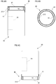
- FIG. 5 is a view showing a container 20 according to the second exemplary embodiment.
- FIG. 5A is a side view of the container 20
- FIG. 5B is a view of the bottom portion 21 of the container 20
- FIG. 5C is a view for explaining the movement of the container 20.
- the container 20 according to the second exemplary embodiment is also provided with the annular projecting portion 211.
- a tape T is adhered on a part of a peak portion of the annular projecting portion 211. Note that, the position where the tape T is adhered is located on a side opposite to a side where the identification mark 23 is provided. More specifically, the identification mark 23 and the tape T are arranged so that phases thereof may be shifted by 180 degrees in the circumferential direction of the container 20.
- the container 20 supplied on the back side of the display device 30 rotates since the friction coefficient of the surface of the tape T is different from the friction coefficient of the other part where the tape is not provided. Specifically, the container 20 rotates while moving to the front side, since the friction force (friction resistance) between the placement unit 31 and the tape T is larger than the friction force between the placement unit 31 and the other part where the tape T is not provided. More specifically, larger resistance force from the placement unit 31 acts on the part where the tape T is provided. Accordingly, the container 20 rotates so that the part where the tape T is not provided may precede.
- the container 20 that is supplied in a state shown with a solid line 5A in FIG. 5C rotates so that the side where the tape T is provided may be turned to the back side as shown with a broken line 5B, and becomes in a state shown with a broken line 5C. That is, the container 20 becomes in a state where the side on which the tape T is provided is positioned at the back side and the identification mark 23 is positioned at the front side. Then, the container 20 moves toward a position shown with a broken line 5D while keeping a state where the identification mark 23 is positioned at the front side.
- the container 20 that reaches the taken-out portion is to be displayed in the state where the identification mark 23 faces the front side.
- plural roll-shaped members or ball-shaped members which are rotatable, may be provided.
- a flat and smooth region is preferably provided on a part of the placement unit 31 (a region where the rotation of the container 20 is performed) , as shown in FIG. 5C. That is, it is preferable that the contact portion with the container 20 should be flat and smooth without roll-shaped members or the like.
- a plate member having a flat and smooth surface and made of vinyl chloride or formed of bakelite is preferably used. In order to prevent occurrence of scratches by the containers 20, a plate member formed of bakelite is more preferable.
- a region relatively difficult to slide region having a relatively large friction coefficient
- a region relatively easy to slide region having a relatively small friction coefficient
- rotation force is applied to the container 20.
- the inventors executed an experiment with the container 20 shown in FIG. 5A, and examined the rotation performance of the container 20, and the like. Note that, in this experiment, the width B of the tape T (refer to FIG. 5B) was set at approximately 2 mm, while the length L of the tape T (length along the circumferential direction of the annular projecting portion 211, refer to FIG. 5B) was set at approximately 2.5 mm. A plate made of vinyl chloride and having a dry, flat and smooth surface was provided at the contact portion with the container 20 in the placement unit 31. The sloping angle of the placement unit 31 was set at 12 degrees. Explanation of the result was given as follows. The container 20 rotated so that the side where the tape T was provided might be turned to the back side, as described above. After that, the container 20 became in the state where the identification mark 23 faced the front side as shown with the broken line 5C in FIG. 5C.
- Regions having different friction force may be formed not only by the adhesion of the tape T, but also by coating, for example.
- the regions having the different friction force may be formed by application of the material that makes the regions have the different friction force.
- the regions having the different friction force may be formed.
- FIG. 6 is a view showing an example in which the regions having the different friction force are formed by coating.
- a first region 211a having a first friction coefficient and a second region 21 Ib having a second friction coefficient larger than the first friction coefficient may be formed on the peak portion (an example of a contact portion being in contact with the placement unit 31) of the annular projecting portion 211 by coating, as shown in FIGs. 6A and 6B.
- the second region 21 Ib is provided on an opposite side to a side where the identification mark 23 is provided.
- the first region 21 Ia is positioned at a region other than the second region 21 Ib.
- the above-described first and second regions 211a and 21 Ib may be formed in the manufacturing process of the container 20, for example.
- the container 20 is transported in a state where the bottom portion 21 is the underside thereof during a drink filling process and the like, after the manufacture. That is, the container 20 is transported in a state where the bottom portion 21 is in contact with the placement face.
- the container 20 may be difficult to smoothly slide, and thus the smooth transportation may be difficult in some cases.
- the container 20 may smoothly move (slide) during the drink filling process and the like.
- this sticker is removed when the container 20 that has been filled with drink is shipped out, or when the container 20 that has been filled with drink is placed on the display device 30.
- explanation has been given for two regions, that is, the first and second regions 211a and 21 Ib, formed on the container 20 as one example. Alternatively, only the second region 21 Ib may be formed.
- the first and second regions 211a and 21 Ib may be formed not only directly on the container 20, but also on the mounting member 40 that is mounted on the bottom portion 21 of the container 20, as shown in FIG. 7 (FIGs. 7A and 7B) (a view for explaining the container 20 and the mounting member 40).
- the mounting member 40 includes the first tubular portion 41 that is cylindrically formed and the second tubular portion 43 that is arranged inside the first tubular portion 41 and also cylindrically formed, similarly to FIGs. 4A to 4C. Further, the mounting member 40 includes the lid portion 42 formed into a disk shape and covers the one end part of the first tubular portion 41.
- the mounting member 40 in this configuration includes an annular projecting portion 44 provided on the lid portion 42.
- the annular projecting portion 44 annularly projects toward the outside of the mounting member 40 (on an opposite side to a side where the mounting member 40 is mounted on the container 20).
- the first region 21 Ia is formed on a part of the peak portion of the annular projecting portion 44
- the second region 21 Ib is formed on the other part. More specifically, the first and second regions 211a and 21 Ib are formed on the opposite side to the side where the mounting member 40 is mounted on the container 20.
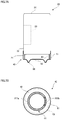
- FIG. 8 is a view showing another configuration of the mounting member 40.
- FIG. 8A is a partial cross sectional view of the container 20 and the mounting member 40
- FIG. 8B is a view of the mounting member 40 seen from the bottom side.
- the annular projecting portion 44 is provided on the lid portion 42 of the mounting member 40.
- the lid portion 42 of the mounting member 40 may be formed to be flat.
- a sticker S having a larger friction coefficient than that of the surface of the lid portion 42 and increasing friction force between the placement unit 31 and the sticker S may be adhered, for example.
- the mounting member 40 in these configurations is mounted on the container 20 so that the sticker S may be positioned on the opposite side to the side where the identification mark 23 is provided, as shown in FIG. 8 A.
- FIGs. 8 A In FIGs.
- the friction force is increased by the sticker S.
- the friction force may be relatively decreased by the sticker S whose surface roughness is made to be smaller than that of the lid portion 42, for example.
- the mounting member 40 in this case is mounted on the container 20 so that the sticker S may be positioned on the side where the identification mark 23 is provided.
Landscapes
- Engineering & Computer Science (AREA)
- Mechanical Engineering (AREA)
- Details Of Rigid Or Semi-Rigid Containers (AREA)
Abstract
The container 20 includes a bottom portion 21 formed into a disk shape, a side portion 22 upwardly extending from the outer circumference edge of the bottom portion 21 and a lid portion 24 attached on an upper part of the side portion 22, and the container 20 is formed into a cylindrical shape. Additionally, the container 20 includes an annular projecting portion 211 provided on the bottom portion 21. The annular projecting portion 211 annularly projects toward an outside of the container 20 (a direction away from the bottom portion 21). Further, the container 20 has an identification mark 23 for differentiating a product from other products, such as a product name, or a trademark, which is applied on a specific portion of the side portion 22 as a part of an outer face. Furthermore, the container 20 has a weight 212 provided on the bottom portion 21.
Description
The present invention relates to a drink container and a mounting member attached to the drink container.
When being sold, for example, in a convenience store, containers, such as drink cans and PET bottles, filled with drink are placed to stand upright on a display device put, for example, in a display case. There, the display device as described above is arranged, for example, in a sloping state so that each container may move frontward in the display case due to its own weight. When one container at a front side (in the front row) is taken out, other containers following that container move toward the front side due to their own weight.
Here, for example, a plastic flat plate is provided, because of good sliding of containers, to a part on which the containers are placed in the display device. Meanwhile, a display device in which a large number of rotatable rollers are arranged has become available in recent years (for example, refer to patent literature 1). Additionally, although containers are supplied from a back side of a display device in general, there is proposed a display device allowing containers to be supplied from a front side, and allowing a container, which has moved backward, to move to the front side again so as to be displayed (for example, refer to patent literature 2). That is, there is proposed a display device in which a container supplied from a front side makes a U-turn and returns. Furthermore, with regard to a container, there has been proposed a can having inside concave portions and vertical ribs alternately formed, in a circumferential direction, in an inner circumferential wall of an annular convex portion formed on a bottom of the can (for example, refer to patent literature 3).
Here, for example, a plastic flat plate is provided, because of good sliding of containers, to a part on which the containers are placed in the display device. Meanwhile, a display device in which a large number of rotatable rollers are arranged has become available in recent years (for example, refer to patent literature 1). Additionally, although containers are supplied from a back side of a display device in general, there is proposed a display device allowing containers to be supplied from a front side, and allowing a container, which has moved backward, to move to the front side again so as to be displayed (for example, refer to patent literature 2). That is, there is proposed a display device in which a container supplied from a front side makes a U-turn and returns. Furthermore, with regard to a container, there has been proposed a can having inside concave portions and vertical ribs alternately formed, in a circumferential direction, in an inner circumferential wall of an annular convex portion formed on a bottom of the can (for example, refer to patent literature 3).
An outer face of a container is provided with a mark, such as a trade name or a trademark, for differentiating a product from other products. If this mark does not face a side from which a purchaser takes out the container, the purchaser finds it difficult to identify the product, and also the product does not look good when being displayed. For this reason, it is preferable that marks on displayed containers face a predetermined direction which is, for example, a front direction or the like.
As a conventional technique described in the official gazettes, there has been proposed a display method (for example, refer to patent literature 4) in which: on an upper face of a sloping shelf plate on which containers are placed, a rod-shaped guide ridge is provided to extend in a sloping direction of the shelf plate; on a bottom portion of each container, a concave fitting portion is provided to connect a position directly under a mark to a position directly under a face opposite to a face where the mark is attached; and the container is displayed by use of this guide ridge and this concave fitting portion. In this display method, plural containers are aligned in a front-back direction by having the concave fitting portions fit to the guide ridge with each of those containers put in such a position that the mark faces frontward. As a result, the containers are displayed with the marks facing frontward.
In Patent literature 4 mentioned above, by performing display of the containers with the concave fitting portions being fit to the guide ridge, the marks are reliably faced frontward. In this invention, however, a supplier of the containers is required to fit the concave fitting portions to the guide ridge every time the supplier puts the container on a display device, and this makes displaying work of the containers troublesome. Additionally, in a case where the mark is formed on only one part of each of the containers, it is feared that there may occur a display failure in which some of the containers are displayed with the marks facing backward. Additionally, in a store or the like, such as a convenience store, where a large number of drinks are sold, work of supplying the containers in a way to make the containers face the same direction is very extensive.
The main object of the present invention is to provide a drink container and the like that enable a mark thereon to face a predetermined direction even if the mark faces a random direction when the container is displayed so as to stand upright in a display device.
In order to attain the object there is provided a drink container to which a present invention is applied, including: a bottom portion that has a contact portion being in contact with a placement face; and a side portion that is provided above the bottom portion and on which an identification mark for differentiating a product from other products is applied at a predetermined portion. The contact portion of the bottom portion has a first region having a first friction coefficient and a second region having a second friction coefficient larger than the first friction coefficient, the second region being provided on an opposite side to a side where the identification mark is provided.
Here, the first region and the second region are formed by application of a material giving a different friction coefficient on at least any one of the first region and the second region. In addition, the first region and the second region are formed by adhering any one of a sticker and a tape giving a different friction coefficient, to at least any one of the first region and the second region. Further, the first region and the second region are formed by giving an unevenness portion to at least the second region.
From another aspect of the present invention, there is provided a drink container to which the present invention is applied, including: a bottom portion; and a side portion that is arranged above the bottom portion and on which an identification mark is applied for differentiating a product from other products. A center of gravity of the drink container is positioned toward a side where the identification mark is provided when the bottom portion is placed on a horizontal plane.
Here, the drink container is formed so that the center of gravity may be positioned toward the side where the identification mark is provided, by additionally attaching a member. In addition, the member has larger specific gravity than that of a material forming the bottom portion and a material forming the side portion. Further, the member is attached to the bottom portion of the drink container.
From further aspect of the present invention, there is provided a drink container to which the present invention is applied, which is a drink container sliding, in a downward direction, on a sloping surface provided in a display device and being to be displayed. The drink container includes: a drink container body that has a bottom portion and a side portion on which an identification mark for differentiating a product from other products is applied, and that is to be filled with drink; and a rotation portion that rotates the drink container body so that the identification mark may face the downward direction when the drink container body slides, in the downward direction, on the sloping surface in a state where the bottom portion is in contact with the sloping surface.
Here, the rotation portion is attached to the drink container body, and is formed of a setting member setting a center of gravity of the drink container body to be positioned toward a side where the identification mark is applied. In addition, the setting member has larger specific gravity than that of a material forming the drink container body. Further, the setting member is attached to the bottom portion of the drink container body. Moreover, the bottom portion includes, at a contact portion with the sloping surface, a first region and a second region respectively having friction coefficients different from each other, and the rotation portion is formed of the first region and the second region included in the bottom portion.
In case of taking the present invention as a mounting member, the mounting member to which the present invention is applied is a mounting member mounted on a drink container having a bottom portion and a side portion that is arranged above the bottom portion and that an identification mark for differentiating a product from other products is applied thereon. The mounting member includes a main body that is to be fitted into the drink container. When the mounting member is mounted on the drink container in a state of having a predetermined positional relationship with the drink container, the mounting member causes a center of gravity of the drink container to be displaced toward a side where the identification mark is applied.
Here, the mounting member at least includes: the main body that is a tubular shape and that is fitted into any one of an upper portion of the drink container and the bottom portion; and a displacement member that displaces a center of gravity of the main body from an axial center of the main body. In addition, the displacement member is provided inside of the main body formed into the tube.
From a furthermore aspect of the present invention, there is provided a mounting member to which the present invention is applied, which is mounted on a bottom portion included in a drink container further including a side portion that is arranged above the bottom portion and on which an identification mark for differentiating a product from other products is applied. The mounting member includes: a first region having a first friction coefficient; and a second region having a second friction coefficient larger than the first friction coefficient, the first region and the second region being provided on an opposite side to a side mounted on the bottom portion.
It is possible to provide a drink container or the like that enables the mark to face a predetermined direction even if the mark faces a random direction when the container is placed to stand upright and displayed in the display device.
Best modes for carrying out the invention will be described below in detail with reference to the accompanying drawings.
- First exemplary embodiment -
FIG. 1 (FIGs. 1A and 1B) is a view showing a schematic configuration of a display device according to the first exemplary embodiment of the present invention.
As shown in FIG. 1A, adisplay device 30 according to the first exemplary embodiment includes a placement unit (placement face) 31 on which containers (drink containers) 20 with drink filled therein are placed, and guides 32 that form moving routes (transportation routes) of the containers 20, and that guide movement of the containers 20. The display device 30 also includes a regulation plate 34, a part of which is formed transparently, which is arranged along one side of the placement unit 31 and which stops movement of the containers 20. Here, each of the guides 32 is fixed to the placement unit 31 by having both ends thereof inserted into openings 33 formed in the placement unit 31. Additionally, although a can shaped as a cylinder is illustrated as an example of each of the containers 20, a container made of resin such as a so-called PET bottle, a so-called bottle can having a cap, or the like may also be used.
- First exemplary embodiment -
FIG. 1 (FIGs. 1A and 1B) is a view showing a schematic configuration of a display device according to the first exemplary embodiment of the present invention.
As shown in FIG. 1A, a
The display device 30 is, as shown in FIG. 1B, put inside a display case 10 installed in a convenience store, a super market or the like. This display case 10 includes a case main body unit 10A formed into a rectangular parallelepiped shape, and doors 10B provided so as to be openable and closable with respect to this case main body unit 10A, which form a main part of the display case 10.
Here, thedisplay device 30 is placed on a shelf (not shown in the figure) provided to the display case 10. On this occasion, the display device 30 is placed so that the side where the regulation plate 34 is provided may be located at the side where the doors 10B are provided. Additionally, the display device 30 is placed so that the side where the regulation plate 34 is provided may be positioned at a lower level than a side opposite to the side where the regulation plate 34 is provided. By this configuration, the placement unit 31 of the display device 30 is arranged in a downward sloping state from a back side of the display case 10 toward a front side thereof (a side of a taken-out portion) from which the containers 20 are taken out.
Here, the
Here, the display case 10 in the first exemplary embodiment also has a door (not shown in the figure) provided on the back side thereof, whereby the back side becomes also openable. The containers 20 are supplied to the display device 30 from this back side. That is, the display case 10 has a configuration where a supplying portion for the containers 20 is provided at the back side of the display case 10, and at the back side of the display device 30. There, the containers 20 having been supplied move (slide) on the placement unit 31 toward the doors 10B. That is, the containers 20 move toward purchasers who purchase the containers 20. Note that, in this description, the side where the doors 10B are provided is sometimes referred to as a front side (frontward), whereas the side opposite to the doors 10B is sometimes referred to as a back side (backward). Additionally, a width direction (a direction orthogonal to a direction in which the containers 20 move) of the display case 10 is sometimes referred to as a lateral direction, or as a width direction.
FIG. 2 (FIGs. 2A and 2B) is a view for explaining the containers 20 according to the first exemplary embodiment.
Thecontainer 20 shown in FIG. 2A includes a bottom portion 21 formed into a disk shape, a side portion 22 upwardly extending from the outer circumference edge of the bottom portion 21 and a lid portion 24 attached on an upper part of the side portion 22, and the container 20 is formed into a cylindrical shape. Additionally, the container 20 includes an annular projecting portion 211 provided on the bottom portion 21. The annular projecting portion 211 annularly projects toward an outside of the container 20 (a direction away from the bottom portion 21). Further, the container 20 has an identification mark 23 for differentiating a product from other products, such as a product name, or a trademark. The identification mark 23 is applied on a specific portion of the side portion 22 as a part of an outer face. Furthermore, the container 20 has a weight 212 provided on the bottom portion 21. Note that the bottom portion 21 and the side portion 22 may be taken as a drink container body which is to be filled with drink. The weight 212 may be taken as a setting member that sets the center of gravity of the drink container body to be positioned toward a side where the identification mark 23 is applied.
The
Note that, a material of the containers 20 is not particularly restricted as long as the material is resistant to alcoholic beverages such as beer, or soft drinks such as juice. For example, a metal such as aluminum or steel, resin such as PET (polyethylene terephthalate), glass, or the like may be used.
Additionally, shapes and types of thecontainers 20 are also not particularly restricted. Examples of the containers 20 include so-called two-piece cans (DI cans), three-piece cans, PET bottles, glass bottles and cans with thread (so-called bottle cans).
Additionally, shapes and types of the
The weight 212 is made of a material having larger specific gravity than the material (for example, aluminum) of the container 20, and the material of the weight 212 is, for example, a metal such as lead. The weight 212 is provided so as to be in contact with the inner side face of the annular projecting portion 211. Further, the weight 212 is provided at an eccentric position with respect to the center of gravity (or the center) of the container 20. Furthermore, the weight 212 is provided on the same side as the side where the identification mark 23 is provided. By this configuration, the container 20 according to the first exemplary embodiment is configured so that the center of gravity may be positioned toward the side where the identification mark 23 is provided in the case where the container 20 is placed on the horizontal plane. The weight 212 may be attached to the container 20 with, for example, adhesion.
With reference to FIG. 2B, the movement of the container 20 in the display device 30 will be explained.
Thecontainer 20 placed on the back side of the display device 30 and having started the movement toward the front side thereof rotates so that the side where the weight 212 is attached may precede, as shown with a solid line 2A, since the weight 212 is attached to the bottom portion 21. Then the container 20 continues the rotation and further moves frontward (refer to a broken line 2B). Thereafter, when the container 20 becomes in a state where the weight 212 is positioned on the front side, the rotation is stopped (refer to a broken line 2C). Since the weight 212 and the identification mark 23 are provided on the same side of the container 20 as described above, when the weight 212 is positioned on the front side, the identification mark 23 is also positioned on the front side. That is, the identification mark 23 faces the front side. Then, the container 20 further moves to the front side while keeping a state where the identification mark 23 faces frontward (refer to a broken line 2D). Therefore, the container 20 having reached the taken-out portion is to be displayed in the state where the identification mark 23 faces frontward. Note that, in FIG. 2B, the display device 30 is exemplified in which plural rotatable roll-shaped members are provided in the placement unit 31.
The
FIG. 3 (FIGs. 3A to 3C) shows other configurations of the container 20.
Theweight 212 may be provided on the bottom portion 21 of the container 20 and outside of the annular projecting portion 211, as shown in FIG. 3A, for example. Alternatively, the weight 212 may be attached on the side portion 22 of the container 20 as shown in FIG. 3B. Instead of them, the weight 212 may be attached on the lid portion 24 as shown in FIG. 3C. However, depending on the attachment position of the weight 212, the container 20 may be defaced in some cases. Thus, it is the most preferable that the weight 212 should be attached to the bottom portion 21 of the container 20.
By using a larger amount of the material forming thecontainer 20 for a portion at the identification mark 23 side, the center of gravity of the container 20 may be set to be positioned toward the identification mark 23 side. However, the illustration thereof is omitted in the first exemplary embodiment. That is, by changing a shape of the container 20 without an additional member such as the weight 212, the center of gravity of the container 20 may be positioned toward the identification mark 23 side. For example, in a manufacturing process (forming process) of the container 20, the container 20 is formed with a bending processing or the like as needed, so as to use a larger amount of the material for the portion at the identification mark 23 side. In this case, since a larger amount of the material is used for the side where the identification mark 23 is provided, the center of gravity of the container 20 is set to be positioned toward the identification mark 23 side.
The
By using a larger amount of the material forming the
Note that, the attachment of the weight 212 to the container 20 is not restricted to the above configurations. For example, the weight 212 may be attached to the container 20 with a mounting member that is mounted on the container 20.
FIG. 4 (FIGs. 4A to 4C) is a view for explaining thecontainer 20 and a mounting member.
For example, as shown in FIG. 4A, theweight 212 may be attached to a mounting member 40 that is mounted on (fits into) the container 20 at the upper portion thereof, and that covers the upper portion of the container 20. Note that the mounting member 40 includes a first tubular portion 41 that is cylindrically formed and mounted on the container 20, and a second tubular portion 43 that is arranged inside the first tubular portion 41 and also cylindrically formed, as shown in FIGs. 4A and 4B. In addition, the mounting member 40 has a lid portion 42 that is formed into a disk shape and that covers one end of the first tubular portion 41. The weight 212 is arranged between the first tubular portion 41 and the second tubular portion 43. More specifically, the weight 212 is arranged inside the first tubular portion 41. Here, the first tubular portion 41 and the lid portion 42 may be taken as a main body formed into a tube and fitting into the upper part of the container 20. The weight 212 may be taken as a displacement member that displaces the center of gravity of the main body from an axial center thereof.
FIG. 4 (FIGs. 4A to 4C) is a view for explaining the
For example, as shown in FIG. 4A, the
The attachment of the mounting member 40 to the container 20 is performed after the identification mark 23 and the weight 212 are aligned. Specifically, as shown in FIG. 4A, the weight 212 is positioned on the side where the identification mark 23 is applied, and then the mounting member 40 is mounted on the container 20. As a result, the center of gravity of the container 20 is positioned toward the identification mark 23 side, similarly to the above configuration. More specifically, the mounting member 40 displaces the center of gravity of the container 20 toward the side where the identification mark 23 is applied, when the mounting member 40 is mounted on the container 20 with a predetermined positional relationship with the container 20.
In the first exemplary embodiment, when the mountingmember 40 is mounted on the container 20, an end part of the second tubular portion 43 of the mounting member 40 bumps into the container 20 (refer to FIG. 4A). Thus, excessive entrance of the container 20 into the mounting member 40 is prevented. The mounting member 40 according to the first exemplary embodiment has space between the container 20 and the lid portion 42 (inside the tubular portion 43), in which a gift or the like may be contained. Note that, the mounting member 40 may be attached on a lower part of the container 20, as described in FIG. 4C, instead of the upper portion of the container 20.
In the first exemplary embodiment, when the mounting
- Second exemplary embodiment -
FIG. 5 (FIGs. 5A to 5C) is a view showing acontainer 20 according to the second exemplary embodiment. Here, FIG. 5A is a side view of the container 20, FIG. 5B is a view of the bottom portion 21 of the container 20, and FIG. 5C is a view for explaining the movement of the container 20.
FIG. 5 (FIGs. 5A to 5C) is a view showing a
As shown in FIGs. 5A and 5B, the container 20 according to the second exemplary embodiment is also provided with the annular projecting portion 211. In the second exemplary embodiment, a tape T is adhered on a part of a peak portion of the annular projecting portion 211. Note that, the position where the tape T is adhered is located on a side opposite to a side where the identification mark 23 is provided. More specifically, the identification mark 23 and the tape T are arranged so that phases thereof may be shifted by 180 degrees in the circumferential direction of the container 20.
The container 20 supplied on the back side of the display device 30 rotates since the friction coefficient of the surface of the tape T is different from the friction coefficient of the other part where the tape is not provided. Specifically, the container 20 rotates while moving to the front side, since the friction force (friction resistance) between the placement unit 31 and the tape T is larger than the friction force between the placement unit 31 and the other part where the tape T is not provided. More specifically, larger resistance force from the placement unit 31 acts on the part where the tape T is provided. Accordingly, the container 20 rotates so that the part where the tape T is not provided may precede.
As a result, thecontainer 20 that is supplied in a state shown with a solid line 5A in FIG. 5C rotates so that the side where the tape T is provided may be turned to the back side as shown with a broken line 5B, and becomes in a state shown with a broken line 5C. That is, the container 20 becomes in a state where the side on which the tape T is provided is positioned at the back side and the identification mark 23 is positioned at the front side. Then, the container 20 moves toward a position shown with a broken line 5D while keeping a state where the identification mark 23 is positioned at the front side. Thus, also in the second exemplary embodiment, the container 20 that reaches the taken-out portion is to be displayed in the state where the identification mark 23 faces the front side.
As a result, the
In the placement unit 31, plural roll-shaped members or ball-shaped members, which are rotatable, may be provided. When the rotation of the container 20 is performed by using difference between the friction force as in the case of the second exemplary embodiment, a flat and smooth region is preferably provided on a part of the placement unit 31 (a region where the rotation of the container 20 is performed) , as shown in FIG. 5C. That is, it is preferable that the contact portion with the container 20 should be flat and smooth without roll-shaped members or the like. Specifically, for example, a plate member having a flat and smooth surface and made of vinyl chloride or formed of bakelite is preferably used. In order to prevent occurrence of scratches by the containers 20, a plate member formed of bakelite is more preferable. In the second exemplary embodiment, a region relatively difficult to slide (region having a relatively large friction coefficient) is formed on the container 20 with the tape T. Alternatively, a region relatively easy to slide (region having a relatively small friction coefficient) may be formed on the container 20 with the tape T, and thereby rotation force is applied to the container 20.
The inventors executed an experiment with the container 20 shown in FIG. 5A, and examined the rotation performance of the container 20, and the like. Note that, in this experiment, the width B of the tape T (refer to FIG. 5B) was set at approximately 2 mm, while the length L of the tape T (length along the circumferential direction of the annular projecting portion 211, refer to FIG. 5B) was set at approximately 2.5 mm. A plate made of vinyl chloride and having a dry, flat and smooth surface was provided at the contact portion with the container 20 in the placement unit 31. The sloping angle of the placement unit 31 was set at 12 degrees. Explanation of the result was given as follows. The container 20 rotated so that the side where the tape T was provided might be turned to the back side, as described above. After that, the container 20 became in the state where the identification mark 23 faced the front side as shown with the broken line 5C in FIG. 5C.
Regions having different friction force (regions having different friction coefficients) may be formed not only by the adhesion of the tape T, but also by coating, for example. In other words, the regions having the different friction force (the regions having the different friction coefficients) may be formed by application of the material that makes the regions have the different friction force. Also, for example, by giving unevenness to the container 20 with sandblasting or the like, the regions having the different friction force (the regions having the different friction coefficients) may be formed.
FIG. 6 (FIGs. 6A and 6B) is a view showing an example in which the regions having the different friction force are formed by coating.
For example, afirst region 211a having a first friction coefficient and a second region 211b having a second friction coefficient larger than the first friction coefficient may be formed on the peak portion (an example of a contact portion being in contact with the placement unit 31) of the annular projecting portion 211 by coating, as shown in FIGs. 6A and 6B. In this configuration, the second region 211b is provided on an opposite side to a side where the identification mark 23 is provided. The first region 211a is positioned at a region other than the second region 211b.
FIG. 6 (FIGs. 6A and 6B) is a view showing an example in which the regions having the different friction force are formed by coating.
For example, a
The above-described first and second regions 211a and 211b may be formed in the manufacturing process of the container 20, for example. Here, the container 20 is transported in a state where the bottom portion 21 is the underside thereof during a drink filling process and the like, after the manufacture. That is, the container 20 is transported in a state where the bottom portion 21 is in contact with the placement face. In this case, if the above-described first and second regions 211a and 211b have been formed, the container 20 may be difficult to smoothly slide, and thus the smooth transportation may be difficult in some cases. To avoid this, after forming the first and second regions 211a and 211b, it is preferable that a process for adhering a sticker or the like for covering these first and second regions 211a and 211b should be added. Thereby, the container 20 may smoothly move (slide) during the drink filling process and the like. Note that, this sticker is removed when the container 20 that has been filled with drink is shipped out, or when the container 20 that has been filled with drink is placed on the display device 30. In the above description, explanation has been given for two regions, that is, the first and second regions 211a and 211b, formed on the container 20 as one example. Alternatively, only the second region 211b may be formed.
The first and second regions 211a and 211b may be formed not only directly on the container 20, but also on the mounting member 40 that is mounted on the bottom portion 21 of the container 20, as shown in FIG. 7 (FIGs. 7A and 7B) (a view for explaining the container 20 and the mounting member 40).
The mountingmember 40 includes the first tubular portion 41 that is cylindrically formed and the second tubular portion 43 that is arranged inside the first tubular portion 41 and also cylindrically formed, similarly to FIGs. 4A to 4C. Further, the mounting member 40 includes the lid portion 42 formed into a disk shape and covers the one end part of the first tubular portion 41. The mounting member 40 in this configuration includes an annular projecting portion 44 provided on the lid portion 42. The annular projecting portion 44 annularly projects toward the outside of the mounting member 40 (on an opposite side to a side where the mounting member 40 is mounted on the container 20). In this configuration, the first region 211a is formed on a part of the peak portion of the annular projecting portion 44, and the second region 211b is formed on the other part. More specifically, the first and second regions 211a and 211b are formed on the opposite side to the side where the mounting member 40 is mounted on the container 20.
The mounting
FIG. 8 (FIGs. 8A and 8B) is a view showing another configuration of the mounting member 40. Here, FIG. 8A is a partial cross sectional view of the container 20 and the mounting member 40, and FIG. 8B is a view of the mounting member 40 seen from the bottom side.
In FIGs. 7A and 7B, an example has been described in which the annular projectingportion 44 is provided on the lid portion 42 of the mounting member 40. On the other hand, as shown in FIGs. 8A and 8B, the lid portion 42 of the mounting member 40 may be formed to be flat. To a part of the lid portion 42 formed to be flat, a sticker S having a larger friction coefficient than that of the surface of the lid portion 42 and increasing friction force between the placement unit 31 and the sticker S may be adhered, for example. The mounting member 40 in these configurations is mounted on the container 20 so that the sticker S may be positioned on the opposite side to the side where the identification mark 23 is provided, as shown in FIG. 8A. In FIGs. 8A and 8B, an example has been described in which the friction force is increased by the sticker S. However, the friction force may be relatively decreased by the sticker S whose surface roughness is made to be smaller than that of the lid portion 42, for example. Note that the mounting member 40 in this case is mounted on the container 20 so that the sticker S may be positioned on the side where the identification mark 23 is provided.
In FIGs. 7A and 7B, an example has been described in which the annular projecting
20 Container
21 Bottom portion
22 Side portion
23 Identification mark
40 Mounting member
41 First tubular portion
42 Lid portion
211 Annular projecting portion
211a First region
211b Second region
212 Weight
S Sticker
T Tape
21 Bottom portion
22 Side portion
23 Identification mark
40 Mounting member
41 First tubular portion
42 Lid portion
211 Annular projecting portion
211a First region
211b Second region
212 Weight
S Sticker
T Tape
Claims (17)
- A drink container comprising:
a bottom portion that has a contact portion being in contact with a placement face; and
a side portion that is provided above the bottom portion and on which an identification mark for differentiating a product from other products is applied at a predetermined portion, wherein
the contact portion of the bottom portion has a first region having a first friction coefficient and a second region having a second friction coefficient larger than the first friction coefficient, the second region being provided on an opposite side to a side where the identification mark is provided. - The drink container according to claim 1, wherein the first region and the second region are formed by application of a material giving a different friction coefficient on at least any one of the first region and the second region.
- The drink container according to claim 1, wherein the first region and the second region are formed by adhering any one of a sticker and a tape giving a different friction coefficient, to at least any one of the first region and the second region.
- The drink container according to claim 1, wherein the first region and the second region are formed by giving an unevenness portion to at least the second region.
- A drink container comprising:
a bottom portion; and
a side portion that is arranged above the bottom portion and on which an identification mark is applied for differentiating a product from other products, wherein
a center of gravity of the drink container is positioned toward a side where the identification mark is provided when the bottom portion is placed on a horizontal plane. - The drink container according to claim 5, wherein the drink container is formed so that the center of gravity may be positioned toward the side where the identification mark is provided, by additionally attaching a member.
- The drink container according to claim 6, wherein the member has larger specific gravity than that of a material forming the bottom portion and a material forming the side portion.
- The drink container according to claim 6, wherein the member is attached to the bottom portion of the drink container.
- A drink container that slides, in a downward direction, on a sloping surface provided in a display device and that is to be displayed, the drink container comprising:
a drink container body that has a bottom portion and a side portion on which an identification mark for differentiating a product from other products is applied, and that is to be filled with drink; and
a rotation portion that rotates the drink container body so that the identification mark may face the downward direction when the drink container body slides, in the downward direction, on the sloping surface in a state where the bottom portion is in contact with the sloping surface. - The drink container according to claim 9, wherein the rotation portion is attached to the drink container body, and is formed of a setting member setting a center of gravity of the drink container body to be positioned toward a side where the identification mark is applied.
- The drink container according to claim 10, wherein the setting member has larger specific gravity than that of a material forming the drink container body.
- The drink container according to claim 10, wherein the setting member is attached to the bottom portion of the drink container body.
- The drink container according to claim 9, wherein
the bottom portion includes, at a contact portion with the sloping surface, a first region and a second region respectively having friction coefficients different from each other, and
the rotation portion is formed of the first region and the second region included in the bottom portion. - A mounting member mounted on a drink container having a bottom portion and a side portion that is arranged above the bottom portion and that an identification mark for differentiating a product from other products is applied thereon, the mounting member comprising:
a main body that is to be fitted into the drink container, wherein,
when the mounting member is mounted on the drink container in a state of having a predetermined positional relationship with the drink container, the mounting member causes a center of gravity of the drink container to be displaced toward a side where the identification mark is applied. - The mounting member according to claim 14, wherein
the mounting member at least includes:
the main body that is a tubular shape and that is fitted into any one of an upper portion of the drink container and the bottom portion; and
a displacement member that displaces a center of gravity of the main body from an axial center of the main body. - The mounting member according to claim 15, wherein the displacement member is provided inside of the main body formed into the tube.
- A mounting member mounted on a bottom portion included in a drink container further including a side portion that is arranged above the bottom portion and on which an identification mark for differentiating a product from other products is applied, the mounting member comprising:
a first region having a first friction coefficient; and
a second region having a second friction coefficient larger than the first friction coefficient, the first region and the second region being provided on an opposite side to a side mounted on the bottom portion.
Applications Claiming Priority (2)
| Application Number | Priority Date | Filing Date | Title |
|---|---|---|---|
| JP2008207443A JP4203119B1 (en) | 2008-08-11 | 2008-08-11 | Beverage container and mounting member |
| JP2008-207443 | 2008-08-11 |
Publications (1)
| Publication Number | Publication Date |
|---|---|
| WO2010018673A1 true WO2010018673A1 (en) | 2010-02-18 |
Family
ID=40239563
Family Applications (1)
| Application Number | Title | Priority Date | Filing Date |
|---|---|---|---|
| PCT/JP2009/003787 Ceased WO2010018673A1 (en) | 2008-08-11 | 2009-08-06 | Drink container and mounting member |
Country Status (3)
| Country | Link |
|---|---|
| JP (1) | JP4203119B1 (en) |
| TW (1) | TW201008839A (en) |
| WO (1) | WO2010018673A1 (en) |
Citations (7)
| Publication number | Priority date | Publication date | Assignee | Title |
|---|---|---|---|---|
| JPH01114551U (en) * | 1988-01-23 | 1989-08-01 | ||
| JPH03113655U (en) * | 1990-03-06 | 1991-11-20 | ||
| JPH11100038A (en) * | 1997-09-26 | 1999-04-13 | Bourbon Corp | Container for food, and food in container filled with content |
| JP2000238788A (en) * | 1999-02-23 | 2000-09-05 | Dssc:Kk | Beverage container |
| JP2000344220A (en) * | 1999-06-02 | 2000-12-12 | Nippon Beer Kk | Container |
| JP3114932U (en) * | 2005-07-21 | 2005-10-27 | 正敏 岡 | container |
| JP2006288676A (en) * | 2005-04-11 | 2006-10-26 | Takahiko Katayama | Method for displaying container containing drink |
-
2008
- 2008-08-11 JP JP2008207443A patent/JP4203119B1/en not_active Expired - Fee Related
-
2009
- 2009-08-06 WO PCT/JP2009/003787 patent/WO2010018673A1/en not_active Ceased
- 2009-08-06 TW TW98126561A patent/TW201008839A/en unknown
Patent Citations (7)
| Publication number | Priority date | Publication date | Assignee | Title |
|---|---|---|---|---|
| JPH01114551U (en) * | 1988-01-23 | 1989-08-01 | ||
| JPH03113655U (en) * | 1990-03-06 | 1991-11-20 | ||
| JPH11100038A (en) * | 1997-09-26 | 1999-04-13 | Bourbon Corp | Container for food, and food in container filled with content |
| JP2000238788A (en) * | 1999-02-23 | 2000-09-05 | Dssc:Kk | Beverage container |
| JP2000344220A (en) * | 1999-06-02 | 2000-12-12 | Nippon Beer Kk | Container |
| JP2006288676A (en) * | 2005-04-11 | 2006-10-26 | Takahiko Katayama | Method for displaying container containing drink |
| JP3114932U (en) * | 2005-07-21 | 2005-10-27 | 正敏 岡 | container |
Also Published As
| Publication number | Publication date |
|---|---|
| JP2010042830A (en) | 2010-02-25 |
| JP4203119B1 (en) | 2008-12-24 |
| TW201008839A (en) | 2010-03-01 |
Similar Documents
| Publication | Publication Date | Title |
|---|---|---|
| US7818866B2 (en) | Method of reinforcing a plastic foam cup | |
| US7918005B2 (en) | Reinforced foam cup, method of and apparatus for manufacturing same | |
| US7552841B2 (en) | Reinforced plastic foam cup, method of and apparatus for manufacturing same | |
| US7694843B2 (en) | Reinforced plastic foam cup, method of and apparatus for manufacturing same | |
| US7536767B2 (en) | Method of manufacturing a reinforced plastic foam cup | |
| WO2010018673A1 (en) | Drink container and mounting member | |
| WO2010018670A1 (en) | Display system and display device | |
| WO2010018666A1 (en) | Display device and display system | |
| WO2010073581A2 (en) | Container, display system and display device | |
| JP4279895B1 (en) | Display system and display device | |
| KR101092475B1 (en) | Rolling shelf structure for showcase of refrigerator | |
| WO2010018678A1 (en) | Drink container | |
| JP2010143636A (en) | Beverage container and fitting member | |
| JP4242918B1 (en) | Display device and display system | |
| WO2010018672A1 (en) | Display device | |
| JP2010142589A (en) | Container for drinks | |
| JP2011167414A (en) | Display device | |
| JP2010167270A (en) | Display system, display device and container | |
| JP2010167269A (en) | Display system, display device and container | |
| JP2010167265A (en) | Container display system, display device, and container | |
| JP2010142614A (en) | Display system and display device | |
| JP2011005247A (en) | Article display system, display and article |
Legal Events
| Date | Code | Title | Description |
|---|---|---|---|
| 121 | Ep: the epo has been informed by wipo that ep was designated in this application |
Ref document number: 09806569 Country of ref document: EP Kind code of ref document: A1 |
|
| NENP | Non-entry into the national phase |
Ref country code: DE |
|
| 122 | Ep: pct application non-entry in european phase |
Ref document number: 09806569 Country of ref document: EP Kind code of ref document: A1 |