WO2010013700A1 - 紙葉類処理装置 - Google Patents
紙葉類処理装置 Download PDFInfo
- Publication number
- WO2010013700A1 WO2010013700A1 PCT/JP2009/063402 JP2009063402W WO2010013700A1 WO 2010013700 A1 WO2010013700 A1 WO 2010013700A1 JP 2009063402 W JP2009063402 W JP 2009063402W WO 2010013700 A1 WO2010013700 A1 WO 2010013700A1
- Authority
- WO
- WIPO (PCT)
- Prior art keywords
- paper sheet
- banknote
- value
- length
- transport
- Prior art date
- Legal status (The legal status is an assumption and is not a legal conclusion. Google has not performed a legal analysis and makes no representation as to the accuracy of the status listed.)
- Ceased
Links
Images







Classifications
-
- G—PHYSICS
- G07—CHECKING-DEVICES
- G07D—HANDLING OF COINS OR VALUABLE PAPERS, e.g. TESTING, SORTING BY DENOMINATIONS, COUNTING, DISPENSING, CHANGING OR DEPOSITING
- G07D7/00—Testing specially adapted to determine the identity or genuineness of valuable papers or for segregating those which are unacceptable, e.g. banknotes that are alien to a currency
- G07D7/16—Testing the dimensions
-
- G—PHYSICS
- G07—CHECKING-DEVICES
- G07D—HANDLING OF COINS OR VALUABLE PAPERS, e.g. TESTING, SORTING BY DENOMINATIONS, COUNTING, DISPENSING, CHANGING OR DEPOSITING
- G07D7/00—Testing specially adapted to determine the identity or genuineness of valuable papers or for segregating those which are unacceptable, e.g. banknotes that are alien to a currency
- G07D7/06—Testing specially adapted to determine the identity or genuineness of valuable papers or for segregating those which are unacceptable, e.g. banknotes that are alien to a currency using wave or particle radiation
- G07D7/12—Visible light, infrared or ultraviolet radiation
Definitions
- the present invention relates to a paper sheet processing apparatus that determines the authenticity of banknotes, gift certificates, coupon tickets, and the like (hereinafter collectively referred to as paper sheets).
- a banknote handling apparatus that handles banknotes, which is an aspect of paper sheets, determines the authenticity of a banknote inserted by a user from a banknote insertion slot, and determines various values depending on the banknote value determined to be authentic. It is incorporated in service devices that provide products and services, such as game media lending machines installed in game halls, or vending machines and ticket machines installed in public places.
- the banknote moving in the banknote transport path is irradiated with light, and transmitted light or reflected light from the banknote is detected by a light receiving sensor, and this is stored as normal data stored in dictionary data. This is done by comparing.
- This authenticity determination process is performed by extracting various features of a banknote, and as one of them, it is known to determine the authenticity by detecting the length of a banknote.
- Patent Document 1 includes a transport roller (transport member) that transports banknotes, a pulse motor that rotationally drives the transport rollers, and a sensor that detects banknotes transported on a transport path, and the sensor Disclosed is a method for determining the authenticity of a bill by counting the number of pulses of a pulse motor while the bill is being detected and taking the product with the carry amount per pulse to determine the length of the bill. Has been. JP-A-5-12527
- the paper sheet processing apparatus includes an insertion port into which a paper sheet is inserted, a transport member that transports the paper sheet inserted into the insertion port, and a paper sheet transported by the transport member.
- a paper sheet reading means for reading, a detection means for detecting an actual measurement value of a length in a predetermined area in the transport direction of the paper sheet read by the paper sheet reading means, and a length of the paper sheet in the predetermined area A storage unit that stores a reference value; and an authenticity determination unit that determines the authenticity of the paper sheet based on a comparison result between the actual measurement value and the reference value, and the reference value is an authentic paper sheet.
- the length in the predetermined area is calculated by reading, and the calculated length, the theoretical value that is the length of the predetermined area of the genuine paper sheet, and the paper sheet that is authentic with respect to the theoretical value in advance It is determined based on the allowable tolerance.
- the predetermined area may include a print area.
- FIG. 1 It is a figure which shows the structure of the banknote processing apparatus which concerns on this embodiment, and is a perspective view which shows the whole structure.
- the perspective view which shows the state which opened the opening-and-closing member with respect to the main body frame of an apparatus main body.
- the right view which showed roughly the conveyance path
- the right view which shows schematic structure of the power transmission mechanism for driving the press board arrange
- the left view which shows schematic structure of the drive source for driving a banknote conveyance mechanism, and a driving force transmission mechanism.
- the timing chart which shows the lighting control of the light emission part in a banknote reading means, and shows the lighting control of the light emission part at the time of reading a banknote.
- the block diagram which shows the structure of the control means which controls the drive of drive members, such as a banknote conveyance mechanism and a banknote reading means.
- the schematic diagram which illustrates the range which acquires the length data of the printing area
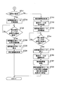
- the flowchart (the 1) explaining the processing operation
- the flowchart (the 2) explaining the processing operation
- the flowchart explaining a conveyance path open process procedure. 7 is a flowchart for explaining a skew correction operation processing procedure.
- the flowchart which shows a conveyance path closing process procedure.
- the schematic diagram which illustrates the length data of the printing area
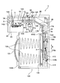
- FIG. 1 to FIG. 5 are diagrams showing the configuration of the banknote handling apparatus according to the present embodiment
- FIG. 1 is a perspective view showing the overall configuration
- FIG. FIG. 3 is a right side view schematically showing a transport path of a bill inserted from the insertion slot
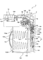
- FIG. 4 is a diagram for driving a pressing plate disposed in the bill housing part.
- FIG. 5 is a right side view illustrating a schematic configuration of the power transmission mechanism
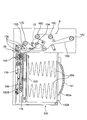
- FIG. 5 is a left side view illustrating a schematic configuration of a driving source and a driving force transmission mechanism for driving the bill conveyance mechanism.
- the banknote handling apparatus 1 of the present embodiment is configured to be incorporated into various gaming machines such as a slot machine, for example, and is provided in the apparatus main body 2 and the apparatus main body 2 to stack and accommodate a large number of banknotes. And a storage unit (storage stacker; safe) 100 that can be used.
- the housing 100 may be detachable from the apparatus main body 2.
- the apparatus main body 2 can be obtained by pulling the handle 101 provided on the front surface in a state where a lock mechanism (not shown) is released. It is possible to remove from.
- the apparatus main body 2 has a main body frame 2A and an opening / closing member 2B configured to be opened and closed with one end portion as a rotation center with respect to the main body frame 2A.
- the main body frame 2 ⁇ / b> A and the opening / closing member 2 ⁇ / b> B when the opening / closing member 2 ⁇ / b> B is closed with respect to the main body frame 2 ⁇ / b> A, a gap in which bills are conveyed to the opposite portions (banknote conveyance path 3) Is formed, and the bill insertion slot 5 is formed on the front exposed side of both so as to coincide with the bill transport path 3.
- the bill insertion slot 5 has a slit-like opening so that it can be inserted into the apparatus main body 2 from the short side of the bill.
- a banknote transport mechanism 6 that transports banknotes along the banknote transport path 3
- an insertion detection sensor 7 that detects a banknote inserted into the banknote insertion slot 5
- an insertion detection sensor 7 is installed on the downstream side of the bill 7 and reads the information of the bill in the transported state
- the skew correction mechanism 10 for accurately positioning and transporting the bill relative to the bill reading means 8, and the bill is skewed.
- a movable piece passage detection sensor 12 that detects that a pair of movable pieces constituting the correction mechanism has passed, and a discharge detection sensor 18 that detects that a bill has been discharged to the bill housing part 100 are provided.
- the banknote transport path 3 extends from the banknote insertion slot 5 toward the back side, extends from the first transport path 3A and the first transport path 3A toward the downstream side, and enters the first transport path 3A.
- a second conveyance path 3B inclined at a predetermined angle and downward is provided.
- the downstream side of the second transport path 3B is bent in the vertical direction, and a discharge port 3a for discharging the banknote is formed in the banknote accommodating part 100 at the downstream end thereof, and discharged from here.
- the bill is fed into the inlet (receiving port) 103 of the bill housing part 100 in the vertical direction.
- the banknote transport mechanism 6 is a mechanism that enables the banknote inserted from the banknote insertion slot 5 to be transported along the insertion direction, and allows the banknote in the inserted state to be transported back toward the banknote insertion slot 5.
- the banknote transport mechanism 6 is rotationally driven by a motor (pulse motor; see FIG. 5) 13 which is a drive source installed in the apparatus main body 2 and the motor 13, and moves along the banknote transport direction in the banknote transport path 3.
- Conveying roller pairs (14A, 14B), (15A, 15B), (16A, 16B), and (17A, 17B) constituting a conveying member disposed at a predetermined interval are provided.
- the pair of transport rollers is installed so that a part thereof is exposed in the banknote transport path 3, and the transport rollers 14 ⁇ / b> B, 15 ⁇ / b> B, 16 ⁇ / b> B, and 17 ⁇ / b> B are all driven below the banknote transport path 3 by the motor 13.
- the transport rollers 14A, 15A, 16A, and 17A installed on the upper side are pinch rollers that are driven by these rollers.
- the conveyance roller pair (14A, 14B) that first clamps the banknote inserted from the banknote insertion slot 5 and transports it to the back side is installed at one central position of the banknote transport path 3, as shown in FIG.
- the transport roller pairs (15A, 15B), (16A, 16B), and (17A, 17B) that are sequentially arranged on the downstream side thereof are spaced apart along the width direction of the banknote transport path 3. Two places are installed.
- the upper conveyance roller 14A is in the state spaced apart from the lower conveyance roller 14B.
- the insertion detection sensor 7 detects this insertion, the upper transport roller 14A is driven toward the lower transport roller 14B to sandwich the inserted bill.
- the upper transport roller 14A is driven and controlled by a roller raising / lowering motor 70 (see FIG. 7) as a drive source so as to contact / separate from the lower transport roller 14B.
- a roller raising / lowering motor 70 see FIG. 7
- the upper transport roller 14 ⁇ / b> A is
- the load on the banknote is released away from the transport roller 14B and the skew correction process is completed, the upper transport roller 14A is driven again toward the lower transport roller 14B to pinch the banknote.
- the skew correction mechanism 10 includes a pair of left and right movable pieces 10A (only one side is shown) that performs skew correction, and the pair of left and right movable pieces 10A is driven by driving a motor 40 for the skew correction mechanism. It moves so that it may approach, and the correction process of the skew with respect to a banknote is performed by this.
- the conveyance rollers 14B, 15B, 16B, and 17B installed on the lower side of the above-described banknote conveyance path 3 are, as shown in FIG. 5, a motor 13 and a pulley installed at the end of the drive shaft of each conveyance roller. It is rotationally driven through 14C, 15C, 16C, and 17C. That is, a drive pulley 13A is installed on the output shaft of the motor 13, and the pulleys 14C, 15C, 16C, and 17C installed at the ends of the drive shafts of the respective transport rollers are connected to the drive pulley 13A.
- the drive belt 13B is wound between the two. A tension pulley is engaged with the drive belt 13B at an appropriate position to prevent looseness.
- the transport rollers 14B, 15B, 16B, and 17B are driven to rotate forward synchronously to transport bills in the insertion direction, and the motor 13 is driven to rotate backward. Then, the conveyance rollers 14B, 15B, 16B, and 17B are synchronously driven in reverse to convey the bill toward the bill insertion slot 5 side.
- the insertion detection sensor 7 generates a detection signal when a banknote inserted into the banknote insertion slot 5 is detected. When this detection signal is issued, the motor 13 is driven to rotate forward, and the banknote is inserted. Transport toward The insertion detection sensor 7 of the present embodiment is installed between the transport roller pair (14A, 14B) and the skew correction mechanism 10, and is configured by an optical sensor, for example, a retroreflective photosensor. However, other than that, it may be constituted by a mechanical sensor.
- the movable piece passage detection sensor 12 generates a detection signal when it is detected that the leading edge of the bill has passed through the pair of left and right movable pieces 10A constituting the skew correction mechanism 10, and this detection signal Is issued, the drive of the motor 13 is stopped, and the skew correction processing is performed.
- the movable piece passage detection sensor 12 of the present embodiment is installed on the upstream side of the bill reading means 8 and is constituted by an optical sensor or a mechanical sensor, similar to the insertion detection sensor.
- emission detection sensor 18 detects the trailing end of the banknote to pass, and detects that the banknote was discharged
- the unit 100 is disposed immediately before the receiving port 103.
- the discharge detection sensor 18 is also composed of an optical sensor or a mechanical sensor, like the insertion detection sensor.
- the bill reading means 8 reads the bill information of the bill conveyed with the skew corrected by the skew correction mechanism 10 and identifies its validity (authenticity).
- the banknote reading means 8 is configured to include a line sensor that performs reading by irradiating light from both sides of a banknote to be conveyed and detecting the transmitted light and reflected light with a light receiving element. And installed in the first transport path 3A.
- the above-described bill reading unit is used to irradiate the printed portion of the bill to be conveyed, receive the transmitted light and reflected light, and receive the printed portion.
- the second authenticity determination process may be performed after the first authenticity determination process is executed, or may be executed before the first authenticity determination process. In the present embodiment, as described later, the second authenticity determination process is performed after the first authenticity determination process is executed.
- light having a predetermined wavelength is irradiated from the light emitting means to the print area on the surface of the bill to be conveyed, and the transmitted light data of the light transmitted through the bill and the reflection are reflected.
- the reflected light data of the obtained light is acquired and compared with the reference data of the genuine banknote stored in advance.
- the genuine banknote since the genuine banknote has a region in which the acquired image data differs depending on the wavelength of light to be irradiated (for example, visible light or infrared light), this point is determined in the first authenticity determination process.
- the authenticity of authenticity I try to raise more. That is, since red light and infrared light have different wavelengths, if transmitted light data or reflected light data from a plurality of lights having different wavelengths is used for determining the authenticity of a bill, it passes through a specific area between a genuine note and a counterfeit bill. Transmitted light and reflected light reflected from a specific region have properties that the transmittance and the reflectance are different. For this reason, the identification accuracy of the authenticity of a banknote is raised more by using the light source of a some wavelength.
- the second authenticity determination process for example, image information on both sides of the banknote is acquired as pixel information along the banknote conveyance direction by the above-described banknote reading unit 8, and each pixel information along the conveyance direction is used to acquire each piece of image information.
- the printing length on the surface is derived, and authenticity determination processing is performed based on this printing length.
- the one whose printing length is different from a genuine banknote is excluded as a fake, and by performing such an authenticity determination process, the identification accuracy of the banknote is further improved. It becomes possible to raise.
- the conveyance amount of the banknote and the conveyance roller pairs (15A, 15B) and (16A, 16B) constituting the conveyance member are used.
- And (17A, 17B) need to be considered. That is, the drive-side transport roller constituting the above-described pair of transport rollers is controlled by a motor (pulse motor) 13 so that a rotational error is controlled, but a manufacturing error occurs in any of the transport rollers. There is a possibility.
- the manufacturing error is considered to be about ⁇ 3/100 mm in diameter at most.
- the rotation amount of the transport roller per pulse (corresponding to the banknote transport amount) is increased.
- the authenticity determination process is performed by determining the print length of the banknote as described above according to the program specified in advance, an error occurs in the actual length detection, and the authenticity determination is performed depending on the banknote processing apparatus. Accuracy may be reduced.
- the banknote handling apparatus changes the reference value for determining that the banknote handling apparatus is a genuine banknote regarding the print length before operating the banknote handling apparatus in accordance with the method described below. That is, by configuring the reference value so that it can be changed for each apparatus, even a banknote processing apparatus incorporating a conveyance roller in which a manufacturing error as described above is incorporated is appropriately based on the length (printing length). It is possible to execute authentication processing.
- the banknote reading means 8 controls the lighting of the light emitting section at a predetermined interval and detects the transmitted light and reflected light when the banknote passes by the line sensor. It becomes possible to acquire image data based on a plurality of pieces of pixel information having a predetermined size as one unit.
- the image data acquired by the line sensor is converted into data including color information having brightness for each pixel by a conversion unit described later.
- the color information for each pixel having lightness converted by the conversion unit corresponds to the luminance value. For example, as 1-byte information, a numerical value from 0 to 255 (0: 255) according to the lightness. Black to 255: White) is assigned to each pixel.
- a predetermined area of the banknote is extracted, pixel information included in the area and pixel information of the same area of the genuine note are used, and these are substituted into an appropriate correlation equation.
- the authenticity can be identified by the correlation coefficient calculated in the above.
- an analog waveform can be generated from transmitted light data or reflected light data, and authenticity can be identified by comparing the shapes of the waveforms.
- the second authenticity determination process it is possible to obtain length data (actual measurement data) regarding the print area from image information obtained from both sides of the banknote.
- the image data acquired as pixel information also depends on the resolution of the line sensor. For example, if one pixel has a resolution of about 0.508 mm in the banknote length direction, the banknote transport direction When acquiring the length from the total number of pixels, it is possible to exclude at least a print length of about 1 to 2 mm as a fake.
- determines that it is a genuine banknote as mentioned above, it sets for every banknote processing apparatus by predetermined operation before an apparatus operate
- the resolution of the line sensor may be increased.
- the identification accuracy is increased too much, even if it is a genuine banknote, The above-mentioned resolution is considered to be sufficient for a line sensor.
- the bill reading means 8 described above is disposed on the opening / closing member 2B side, and a light emitting unit 80 including a first light emitting unit 80a capable of irradiating infrared light and red light on the upper side of a conveyed bill, and a main body frame
- the light emitting / receiving unit 81 is disposed on the 2A side (the light emitting unit 80 and the light emitting / receiving unit 81 are collectively referred to as a reading unit).
- the light receiving / emitting unit 81 is disposed adjacent to both sides of the light receiving unit 81a in the bill conveyance direction, and includes a light receiving unit 81a including a light receiving sensor facing the first light emitting unit 80a so as to sandwich the bill. And a second light emitting portion 81b that can emit light.
- the first light emitting unit 80a disposed opposite to the light receiving unit 81a functions as a light source for transmission.
- the first light emitting unit 80a is formed of a rectangular rod-shaped body made of synthetic resin that emits light from the LED element 80b attached to one end through a light guide 80c provided inside.
- the 1st light emission part of such composition is arranged in the shape of a line in parallel with light reception part 81a (light reception sensor), and is simple composition, and with respect to the whole conveyance path width direction range of the bill conveyed It becomes possible to irradiate uniformly as a whole.
- the light receiving unit 81a of the light receiving / emitting unit 81 is formed in a strip shape extending in the crossing direction with respect to the banknote transport path 3 and having a width that does not affect the sensitivity of a light receiving sensor (not shown) provided in the light receiving unit 81a. It is formed into a thin plate shape.
- the light receiving sensor is provided with a plurality of CCDs (Charge Coupled Devices) in the center of the light receiving portion 81a in the thickness direction, and condenses transmitted light and reflected light above the CCD.
- the line sensor is configured as a so-called line sensor in which a green lens array 81c is arranged in a line shape.
- the transmitted light or reflected light of infrared light or red light from the first light emitting unit 80a or the second light emitting unit 81b irradiated toward the bill to be determined as authenticity is received, and the lightness is used as the light reception data. It is possible to generate pixel data (pixel data including color information having lightness and having a predetermined size as one unit) corresponding to the two-dimensional image from this pixel data.
- the second light emitting unit 81b of the light emitting / receiving unit 81 functions as a light source for reflection.
- the second light emitting unit 81b is made of a synthetic resin that can uniformly irradiate light from the LED element 81d attached to one end through the light guide 81e provided inside. It is composed of a rectangular bar.
- the second light emitting unit 81b is also configured to be arranged in a line parallel to the light receiving unit 81a (line sensor).
- the second light emitting unit 81b can irradiate light toward the banknote at an elevation angle of 45 degrees, for example, and is disposed so that reflected light from the banknote is received by the light receiving unit 81a.
- the light emitted from the second light emitting unit 81b is incident on the light receiving unit 81a at 45 degrees, but the incident angle is not limited to 45 degrees, and there is no shading with respect to the surface of the banknote. If light can be irradiated uniformly, the installation state can be appropriately set. For this reason, about the arrangement
- the second light emitting unit 81b is installed on both sides with the light receiving unit 81a in between so that light is irradiated from both sides at an incident angle of 45 degrees. This is because if there are scratches or folds on the banknote surface, and light is irradiated only from one side to the irregularities generated on these scratches or folds, the irregularities will inevitably become blocked by light. A spot may occur. For this reason, by irradiating light from both sides, it is possible to prevent shadows from being formed in the uneven portions, and to obtain image data with higher accuracy than irradiation from one side. Of course, about the 2nd light emission part 81b, the structure installed only in one side may be sufficient.
- the configurations and arrangements of the light emitting unit 80 and the light emitting / receiving unit 81 described above are not limited to the present embodiment, and can be appropriately modified.
- the lighting is controlled at predetermined intervals. That is, the four light sources including the light source for transmitting red light and infrared light and the light source for reflecting red light and infrared light in the first light emitting unit 80a and the second light emitting unit 81b are arranged at a predetermined interval (predetermined). The lighting control is repeated so that two or more light sources are not turned on at the same time without repeating the phases of the light sources.
- the other three light sources are controlled to be turned off.
- the light of each light source is detected at regular intervals, and the transmitted light and reflected light of red light, the transmitted light and reflected light of infrared light are used.
- Pixel data having the lightness of the print area of the banknote can be acquired, and the print length on both sides can be measured. In this case, the resolution can be increased by controlling the lighting interval to be short.
- the banknote accommodating part 100 which accommodates the banknote etc. which were mentioned above laminates
- the main body frame 100 ⁇ / b> A that constitutes the banknote accommodating part 100 is configured in a substantially rectangular parallelepiped shape, and an urging means (biasing spring) 106 is provided inside the front wall 102 a.
- an urging means biasing spring
- One end is attached, and the other end is provided with a placing plate 105 for sequentially stacking banknotes fed through the receiving port 103 described above. For this reason, the mounting plate 105 is in a state of being urged toward the pressing plate 115 described later via the urging means 106.
- a press standby unit 108 is provided so as to wait and hold the falling banknote as it is so as to be continuous with the receiving port 103.
- a pair of regulating members 110 are arranged on both sides of the pressing standby portion 108 on the placement plate side so as to extend in the vertical direction. Between the pair of regulating members 110, an opening is formed so that the pressing plate 115 passes when banknotes are sequentially stacked on the placing plate 105.
- projecting walls are formed on both side walls in the main body frame 100A so that when the mounting plate 105 is pressed by the urging means 106, the mounting plate abuts.
- the projecting wall applies both sides of the uppermost bill and stacks the bills to be laminated. Plays the role of holding stably.
- a pressing plate 115 is provided in the main body frame 100A to press the bills that have dropped from the receiving port 103 onto the pressing standby unit 108 toward the placement plate 105.
- the pressing plate 115 is configured to have a size that allows the opening formed between the pair of regulating members 110 to reciprocate. The position where the pressing plate 115 enters the opening and presses the bill against the placement plate 105. It is reciprocated between the (pressing position) and a position (initial position) where the pressing standby part 108 is opened. In this case, the banknote passes through the opening while being bent by the pressing operation of the pressing plate 115 and is mounted on the mounting plate 105.
- the pressing plate 115 is reciprocated as described above via the pressing plate driving mechanism 120 disposed in the main body frame 100A.
- the pressing plate driving mechanism 120 includes a pair of link members 115a and 115b whose both ends are pivotally supported by the pressing plate 115 so that the pressing plate 115 can be reciprocated in the direction of arrow A in FIGS.
- These link members 115a and 115b are connected in an X shape, and the opposite ends of the link members 115a and 115b are pivotally supported by a movable member 122 that is installed so as to be movable in the vertical direction (arrow B direction).
- a rack is formed on the movable member 122, and a pinion constituting the pressing plate driving mechanism 120 is engaged with the rack.
- a housing part side gear train 124 that constitutes the pressing plate drive mechanism 120 is connected to the pinion.
- a drive source (motor 20) and a main body side gear train 21 that sequentially meshes with the motor 20 are disposed in the apparatus main body 2 described above.
- the main body side gear train 21 is connected to the housing part side gear train 124.
- the accommodating portion side gear train 124 includes a gear 124B disposed coaxially with the pinion, and gears 124C and 124D that sequentially mesh with the gear 124B, and the bill accommodating portion 100 with respect to the frame 2A of the apparatus main body 2.
- the gear 124 ⁇ / b> D is configured to mesh with and separate from the final gear 21 ⁇ / b> A of the main body side gear train 21.
- the above-described pressing plate 115 is rotated by the motor 20 provided in the apparatus main body 2, so that the main body side gear train 21 and the pressing plate driving mechanism 120 (the accommodating portion side gear train 124, the movable member 122). And the link members 115a, 115b, etc.) are reciprocated in the direction of arrow A.
- the main body frame 100A is provided with a conveying member 150 that can come into contact with the bills carried from the receiving port 103.
- the conveying member 150 is in contact with the banknotes to be carried in and stably presses the banknotes in a proper position of the press standby unit 108 (when the banknotes are pressed by the pressing plate 115, the banknotes are not moved sideways and are stably pressed. It plays a role of guiding to a possible position).
- the conveying member is configured by a belt-like member (hereinafter referred to as a belt 150) installed so as to face the pressing standby unit 108.
- the belt 150 is installed so as to extend along the carry-in direction with respect to the banknote, and is wound around a pair of pulleys 150A and 150B rotatably supported at both ends in the carry-in direction. . Further, the belt 150 is in contact with an axially extending conveying roller 150C supported rotatably in the region of the receiving port 103, sandwiches the banknotes carried into the receiving port 103, and presses the banknotes as they are. The standby unit 108 is guided. Further, in the present embodiment, the belt 150 is provided in a pair of left and right so as to sandwich the above-described pressing plate 115 so as to be able to contact the surfaces of both sides of the bill. In addition to the winding of the pulleys 150A and 150B at both ends, the belt 150 may be applied with a tension pulley at an intermediate position to prevent looseness.
- the pair of belts 150 are driven by the motor 13 that drives the above-described plurality of conveying rollers installed in the apparatus main body 2.
- the above-described drive belt 13B driven by the motor 13 is wound around a pulley 13D for driving force transmission, and is used for power transmission that is sequentially installed on this pulley 13D.
- a gear train 153 installed at an end portion of a support shaft of a pulley 150A rotatably supported on the receiving port 103 side meshes with the gear train 13E.
- the input gear of the gear train 153 is engaged with the final gear of the gear train 13 ⁇ / b> E, and the pair of belts 150 are rotated by the motor 13.
- the motor 13 By driving, it is rotated integrally with the above-described transport rollers 14B, 15B, 16B, and 17B for transporting banknotes.
- the banknote transport path 3 has a first transport path 3 ⁇ / b> A extending from the banknote insertion slot 5 toward the back side, and a first transport path 3 ⁇ / b> A extending downstream from the first transport path 3 ⁇ / b> A.
- the second conveyance path 3B has a shutter that prevents conveyance of banknotes toward the banknote insertion slot 5 due to fraud.
- a member 170 is installed.
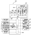
- control means 200 for controlling the driving of the driving members such as the banknote transport mechanism 6 and the banknote reading means 8 will be described with reference to the block diagram of FIG.
- the control means 200 shown in the block diagram of FIG. 7 includes a control board 210 that controls the operation of each drive device described above. On the control board 210, the drive of each drive device is controlled and banknote identification is performed.
- a CPU Central Processing Unit
- ROM Read Only Memory
- RAM Random Access Memory
- the ROM 222 In the ROM 222, operation programs for various driving devices such as the motor 13 for the bill transport mechanism, the motor 20 for driving the pressing plate, the motor 40 for the skew correction mechanism, the motor 70 for raising and lowering the rollers, and the authenticity determination unit 230 Permanent data such as various programs such as an authentication program are stored. In addition, as will be described later, the ROM 222 stores a program for changing the reference value relating to the printing length of the banknote specified in advance to a new reference value by carrying a genuine note.
- the CPU 220 operates according to the program stored in the ROM 222, inputs / outputs signals to / from the various driving devices described above via the I / O port 240, and performs overall operation control of the banknote processing device. . That is, the CPU 220 is connected to the banknote transport mechanism motor 13, the pressing plate driving motor 20, the skew correction mechanism motor 40, and the roller lifting motor 70 via the I / O port 240. The operation of these drive devices is controlled by a control signal from the CPU 220 in accordance with an operation program stored in the ROM 222.
- detection signals from the insertion detection sensor 7, the movable piece passage detection sensor 12, and the discharge detection sensor 18 are input to the CPU 220 via the I / O port 240, and based on these detection signals.
- drive control of the various drive devices described above is performed.
- a detection signal based on transmitted light or reflected light of the light irradiated on the identification target is input to the CPU 220 from the light receiving unit 81a in the bill reading means 8 described above via the I / O port 240. It has become.
- the CPU 220 is connected to the first light emitting unit 80 a and the second light emitting unit 81 b in the bill reading means 8 described above via the I / O port 240.
- the first light emitting unit 80 a and the second light emitting unit 81 b are controlled to be turned on and off by the control signal from the CPU 220 via the light emission control circuit 260 in accordance with the operation program stored in the ROM 222 described above.
- the RAM 224 temporarily stores data and programs used when the CPU 220 operates, and acquires and temporarily receives the received light data (image data composed of a plurality of pixels) of bills that are identification objects. It has a function to memorize.
- the authenticity determination unit 230 has a function of performing the first authenticity determination process and the second authenticity determination process for the banknote to be conveyed, and identifying the authenticity of the banknote.
- the authenticity determination unit 230 converts the received light data of the identification target stored in the RAM 224 into pixel information including color information having brightness for each pixel, and is converted by the conversion unit 232.
- Image data related to the banknote obtained from the reflected light and transmitted light such as specifying the print length of the conveyed banknote based on the obtained pixel information, or performing correction processing as described later based on the print length.
- a data processing unit 231 having a processing function.
- the authenticity determination unit 230 includes a reference data storage unit 233 that stores reference data related to a genuine banknote, comparison data that has been subjected to various types of data processing on a banknote that is a target of authentication in the data processing unit 231, and a reference A comparison / determination unit 235 that compares the reference data stored in the data storage unit 233 and performs authenticity determination processing.
- the reference data storage unit 233 for example, image data related to the genuine banknote used when the first authenticity determination process described above is performed, and printing related to the authentic banknote used in the second authenticity determination process described above.
- a long theoretical value, a reference value that is allowed from the theoretical value and is determined to be a genuine banknote, and the like are stored.
- the above-described reference data is stored in the dedicated reference data storage unit 233, but may be stored in the ROM 222 or RAM 224 described above.
- the reference data storage unit 233 in the authenticity determination unit 230 can rewrite the reference value related to the print length related to the genuine banknote among the reference data described above. As will be described later, the reference value rewriting process is performed by carrying in a genuine banknote (or a reference paper) and measuring the print length before the banknote processing apparatus is operated.
- the bill reading means 8 irradiates the bills conveyed by the bill conveyance mechanism 6 with light (red light, infrared light) from the first light emitting unit 80a and the second light emitting unit 81b.
- the transmitted light or reflected light is received by the light receiving unit (line sensor) 81a, and the bill is read.
- a large number of pieces of pixel information having a predetermined size as one unit for example, one pixel in the transport direction is 0.508 mm
- the image data constituted by a large number of pixels (a plurality of pixels) acquired in this manner is stored in a storage unit such as the RAM 224.
- the image data composed of a large number of pixels stored here is converted by the conversion unit 232 into color information having brightness for each pixel (numerical values from 0 to 255 (0: black to 255: white depending on the brightness)). ) Is converted to information including the assigned color information).
- the conversion unit by converting the image obtained by the line sensor into pixel information including color information having lightness by the conversion unit, it is possible to actually measure the print length of the conveyed banknote. For example, as illustrated in FIG. 8, when the banknote is transported (transported in the D1 direction), the brightness of the pixel information becomes low in the print area when the non-print area shifts to the print area. Accordingly, the brightness of the average pixel information in the width direction D2 is measured, and the displacement position is detected by setting a threshold value, so that the print length R (here, all the prints in the longitudinal direction) It is possible to acquire actual measurement data related to the area.
- the print length R here, all the prints in the longitudinal direction
- a new reference value unique to the bill processing apparatus is set based on the genuine bill. This is to change a reference value (reference value for discriminating that it is a genuine banknote) relating to the printing length of a banknote specified in advance as a program, and the reference value is changed by the following procedure.
- the reference value specified in advance is set to a value obtained by adding an allowable range that is allowed to be a genuine banknote to the theoretical value of the banknote printing length (the length of the printing length of a genuine banknote).
- the theoretical value of the print length of the banknote is 100 (100 pixels)
- the allowable range of the measurement result when actually reading the inserted banknote is assumed to be 2 pixels.
- the reference value (allowable value) is set to 102 pixels. That is, in the banknote reading means 8, it is assumed that if the result of the reading process is 102 pixels, it is determined as a genuine note, and if it is 103 pixels or more, it is determined as a false note.
- a genuine note including an actual banknote or a reference blank sheet
- the reference value before the change process is more likely to be determined as a fake even if it is a genuine banknote.
- the actual measurement value will be 103 pixels or more, so there is a high possibility that it will be determined as a fake even though it is a genuine banknote. .
- the reason why the actual measured value is 102 pixels is considered to be mainly based on the manufacturing error of the transport roller (it is considered to be larger than the theoretical diameter), and the diameter of the transport roller is a manufacturing error. If the value is increased, the amount of bills to be fed increases and the actual measurement value is greatly displaced.
- a new reference value setting process is performed on the basis of the above-described actual measurement value, the theoretical value of the printing length of the genuine banknote, and the reference value (allowable value) before the change process.
- Authentication processing can be performed.
- the new reference value is changed based on the following formula, for example.
- New standard value (actual value / theoretical value) x (standard value before change)
- the actual measurement value is 102 pixels
- the theoretical value is 100 pixels
- the reference value before the change is 102 pixels.
- the reference value of the banknote processing apparatus is set to 104 pixels (rewriting process).
- the rewriting process as described above can be performed at the time of adjustment inspection after the banknote handling apparatus is manufactured. For example, if there is “execution of white correction” as an adjustment inspection item, the rewriting process can be performed simultaneously with the white correction process.
- This white correction conveys a blank paper, specifically, a blank paper having a length that matches the printing length of the official banknote to the banknote reading unit 8 (preferably a polymer with no fear of dimensional change is preferred as the material).
- the white correction process it is possible to acquire the above-described actual measurement value by reading the length of the white paper with the light receiving unit 81a of the bill reading means 8.
- the banknote handling apparatus is configured to read paper sheets on which a barcode is written in addition to banknotes, white correction is performed using a sensor (barcode sensor) that reads barcode information. It is also possible to perform processing and rewriting processing of the reference value described above.
- an actual measurement value is obtained by carrying in one banknote (may be a blank paper).
- an average of the actual measurement values is obtained by carrying in a plurality of banknotes or white paper.
- a value may be acquired and the new reference value described above may be calculated.
- the reference value is higher than the theoretical value (102 pixels).
- the reference value is determined with a predetermined width (for example, 98 to 102 pixels) around the theoretical value. Also good.
- the transport roller pair (14A, 14B) installed in the vicinity of the bill insertion slot is in a separated state in the initial state (see ST16 and ST56 described later).
- the pressing plate 115 has a pair of link members 115a and 115b for driving the pressing plate 115 positioned in the pressing standby unit 108, and a bill is transferred from the receiving port 103 to the pressing standby unit 108 by the pair of link members 115a and 115b. It is set to a standby position where it cannot be loaded. That is, in this state, since the pressing plate 115 enters the opening formed between the pair of regulating members 110, the banknotes stored in the banknote storage unit cannot be extracted through the openings. It has become.
- the pair of movable pieces 10A constituting the skew correction mechanism 10 located on the downstream side of the transport roller pair (14A, 14B) has a minimum width (for example, a pair of movable pieces so that all bills cannot be pulled out in the initial state).
- the distance of 10A is 52 mm; see ST15 and ST57 described later).
- the operator can easily insert even a banknote with a hook.
- the motor 20 for driving the pressing plate 115 described above is reversely driven by a predetermined amount (ST02), and the pressing plate 115 is moved to the initial position. That is, until the insertion detection sensor 7 detects the insertion of the banknote, the pressing plate 115 is in a state of being moved to the opening formed between the pair of regulating members 110, and the opening is interposed through the opening.
- the bills are set so that they cannot pass through.
- the press standby section 108 When the pressing plate 115 is moved from the standby position to the initial position, the press standby section 108 is in an open state (see FIG. 4), and the banknote can be carried into the banknote storage section 100.
- the pressing plate 115 by rotating the motor 20 in a reverse direction by a predetermined amount, the pressing plate 115 has the main body side gear train 21 and the pressing plate driving mechanism 120 (the rack formed on the housing portion side gear train 124, the movable member 122, and the link member). 115a, 115b, etc.) from the standby position to the initial position.
- the above-described roller raising / lowering motor 70 is driven to move the upper conveyance roller 14A so as to contact the lower conveyance roller 14B. Thereby, the inserted banknote is clamped by the transport roller pair (14A, 14B) (ST03).
- the banknote transport path is opened (ST04).
- the release process is performed by driving the pair of movable pieces 10A in a direction away from each other by driving the skew correction mechanism motor 40 in the reverse direction (see FIG. 12).
- ST100 the movable piece detection sensor that detects the position of the pair of movable pieces 10A detects that the pair of movable pieces 10A has moved to a predetermined position (maximum width position) (ST101)
- the motor 40 is driven in reverse rotation. Is stopped (ST102).
- the bill can enter the pair of movable pieces 10A.
- the banknote transport path 3 is in a closed state by a transport path closing process (ST15, ST57) described later.
- the banknote transport path 3 is closed before the banknote is inserted.
- the element such as the line sensor from being damaged by inserting a plate-like member from the bill insertion slot for illegal purposes.
- the bill conveyance motor 13 is driven to rotate forward (ST05).
- the bill is transported into the apparatus by a pair of transport rollers (14A, 14B), and when the movable piece passage detection sensor 12 disposed downstream of the skew correction mechanism 10 detects the leading edge of the bill, the bill is transported.
- the motor 13 is stopped (ST06, ST07).
- the banknote is located between the pair of movable pieces 10 ⁇ / b> A constituting the skew correction mechanism 10.
- skew correction operation processing is performed (ST09).
- This skew correction operation process is performed by driving the pair of movable pieces 10A in a direction approaching each other by driving the above-described skew correction motor 40 in a normal direction. That is, in the skew correction operation process, as shown in the flowchart of FIG. 13, the pair of movable pieces 10A are moved in a direction approaching each other by driving the motor 40 in the normal direction (ST110). This movement of the movable piece is executed until it reaches the minimum width (for example, width 62 mm) of the banknote registered in the reference data storage unit in the control means, whereby the banknote is moved by the movable piece 10A applied to both sides. The skew is corrected and positioned so as to be an accurate center position.
- the conveyance path opening process is subsequently executed (ST10). This is achieved by moving the pair of movable pieces 10A in the direction of separating by driving the skew correction mechanism motor 40 in the reverse direction (see ST100 to ST102 in FIG. 12).
- the roller raising / lowering motor 70 described above is driven to move the upper conveyance roller 14A so as to contact the lower conveyance roller 14B, and the bills are held between the conveyance roller pair (14A, 14B) (ST11).
- the bill conveyance motor 13 is driven to rotate forward to convey the bill toward the inside of the apparatus, and when the bill passes the bill reading means 8, the bill reading process is started (ST12, ST13).
- the four light sources consisting of the light sources for reflection are repeatedly turned on and off at regular intervals, and the lighting control is performed so that two or more light sources do not turn on at the same time without overlapping the phases of the light sources. . In other words, when a certain light source is turned on, lighting control is performed so that the other three light sources are turned off.
- the light of each light source is detected at regular intervals, and the transmitted light and reflected light of red light, the transmitted light and reflected light of infrared light are used. It is possible to read an image composed of grayscale data of the print area of the identification object.
- the closing process of the banknote conveyance path 3 will be performed (ST15).
- the motor 40 described above is driven to rotate forward, thereby a pair of movable pieces. 10A is moved in a direction approaching each other (ST130).
- the movable piece detection sensor detects that the movable piece 10A has moved to a predetermined position (minimum width position, for example, 52 mm) (ST131)
- the forward rotation drive of the motor 40 is stopped (ST132).
- the pair of movable pieces 10A are moved to the minimum width position (width 52 mm) narrower than the width of any bill that can be inserted, thereby effectively preventing withdrawal of the bill.
- the distance between the movable pieces 10A becomes narrower than the width of the inserted banknote, and the operator turns the banknote toward the insertion slot for improper purposes. It is possible to effectively prevent an action such as pulling out.
- a predetermined process may be executed. For example, an unauthorized operation signal (abnormality detection signal) is transmitted to a higher-level device that manages the operation of the banknote processing device, or a notification lamp is provided in the banknote processing device, and processing such as flashing is executed. Also good. Or you may make it perform appropriate processes, such as invalidating operation
- the roller raising / lowering motor 70 described above is driven to separate the conveyance roller pair (14A, 14B) that can hold the banknotes.
- a separation process is performed (ST16).
- the banknote transport motor 13 When the banknote reading means 8 reads data to the rear end of the banknote together with the above-described closing process of the banknote transport path, the banknote transport motor 13 is driven by a predetermined amount and the banknote is moved to a predetermined position (escrow position; At this time, the authentication data is stored in the reference data storage unit 233 in the authenticity determination unit 230 of the control unit 200 described above. With reference to the reference data, the comparison / determination unit 235 executes a bill authenticity determination process (ST17 to ST20).
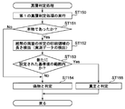
- the first authenticity determination process described above is executed (ST150).
- the first authenticity determination process when the banknote is determined to be genuine (ST151, Yes), the following second authenticity determination process, that is, the authenticity determination process based on the print length is performed. If the bill is determined to be fake in the authenticity determination process 1 (No in ST151), the bill is determined to be fake without executing the second authenticity determination process (ST154).
- the bill reading means 8 detects the length (measured data) of a predetermined print area of the bill (ST152). Next, it is determined whether or not the actual measurement data exists within the range of the new reference value that has been rewritten as described above (ST153). In this case, if the new measured value exists within the range of the new reference value (ST153, Yes), it is determined that the banknote is authentic (ST155).
- the banknote transport motor 13 When the banknote is transported in the process of ST22, the banknote transport motor 13 is driven to rotate forward (ST23) until the rear end of the banknote is detected by the discharge detection sensor 18, and the rear end of the banknote is the discharge detection sensor 18. , The bill conveyance motor 13 is driven forward by a predetermined amount (ST24, ST25).
- the bill is carried into the receiving port 103 of the bill storage unit 100 from the discharge port 3a on the downstream side of the bill transport path 3 of the apparatus body 2.
- the pair of belts 150 are in contact with both side surfaces of a bill to be carried in, and correspond to a driving amount that is stably guided to the press standby unit 108. That is, after the trailing edge of the banknote is detected by the discharge detection sensor 18, the pair of belts 150 come into contact with the banknotes to be carried in by further rotating the banknote transport motor 13 by a predetermined amount. While being driven in the feeding direction, the banknote is guided to the press standby unit 108 in a stable state.
- the raising / lowering motor 70 is driven, and the conveyance roller pair (14A, 14B) in a state of sandwiching the bill is separated (ST55, ST56). Thereafter, the conveyance path closing process is carried out (see ST57, ST130 to ST132 in FIG. 14), and the driving plate 20 is driven forward by a predetermined amount (ST58), so that the pressing plate at the initial position is driven. 115 is driven to the standby position, and a series of processing ends.
- the banknote processing apparatus 1 having the above-described configuration, since the authenticity determination process based on the print length of the banknote is executed, the accuracy of the authenticity determination can be improved, and the authenticity determination process based on the print length is executed. At this time, even if there is a manufacturing error in the transport roller as the transport member, it is possible to accurately determine the authenticity.
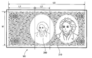
- FIG. 16 schematically shows a banknote for explaining another embodiment.
- the banknote M1 has a length L0 of the print area 310 in the transport direction and a width W of the print area in the width direction perpendicular to the transport direction.
- a watermark region 300 capable of determining the authenticity of the bill is provided in the transport direction by a length L2 at a distance L1 from the front end of the print region in the transport direction of the bill M1.
- the length L0 of the print region 310 can be measured in units of pixels by the light emitting / receiving unit 81 of the banknote reading means 8.
- the print area is not necessarily dark. However, if the brightness is measured in the width W direction and an average value is taken, the start position and end position of the print area 310 can be accurately read by setting a predetermined threshold value.
- the reason why the total length L0 of the print area 310 is used is that correction by actual measurement is performed more accurately. For example, if the distance L1 from the start of the print area 310 to the identification area 300 is used, L1 is approximately 1/3 of L0, and the setting accuracy is also approximately 1/3. Similarly, the absolute value of the error in the conveyance direction in the identification area 300 also decreases according to the ratio of the length L2 to L0, so that the influence on the authenticity determination process is reduced.
- the set new reference range is 99 to 104. Therefore, when the measured value of L0 is 103 or 98, the former (103) is within the allowable range of the new standard, but the latter (98) is out of the allowable range of the new standard.
- 99 ( 0.98 ⁇ 102; rounded down). Therefore, when the measured value of L0 is 103 or 98, the former (103) is outside the allowable range of the new standard, but the latter (98) is within the allowable range of the new standard.
- L0 is known as a diameter error. Therefore, the original L0 standard allowable range is 98 to 102, and the new standard range is 99 to 104. In this case, it goes without saying that it is not necessary to change the allowable range of the width W.
- the length data acquisition method and the area (length) to be acquired can be appropriately changed in consideration of the degree of error and the system required for authenticity determination.
- the configuration may be such that only the length data of the area where the banknote watermark is formed is acquired.
- the paper sheet processing apparatus having the above-described configuration, even if there is a manufacturing error in the conveyance member installed for each apparatus, for example, the genuine paper sheet is read and the length is calculated and read before the apparatus is operated. Since the reference value of the length of the sheet unique to the apparatus is specified by using the length, accurate authentication can be performed.
- a reference value for the length in a predetermined area of the paper is stored in advance, and a storage unit that stores an actual measured value of the length in the predetermined area in the transport direction of the paper sheet read by the light emitting and receiving unit; the transport member; and the light emission
- a paper sheet processing apparatus including a processor capable of controlling the unit can be provided.
- the processor controls the conveyance of the paper sheet by the conveyance member, causes the paper receiving / emitting unit to read the paper sheet in association with the conveyance amount, and determines the length of the predetermined area of the paper sheet. Is measured by the light emitting / receiving unit and the conveying member, and the measured value is stored in the storage unit. Based on the reference value stored in advance, a preset allowable value, and a new allowable value based on the measured value The first authenticity determination of the paper sheet is performed, the actual measurement value of the predetermined area of the paper sheet is compared with the new allowable value, and whether or not the actual measurement value is within an allowable range. The authenticity can be determined.
- a reference value for the length in a predetermined area of the paper is stored in advance, and a storage unit for storing an actual measured value of the length in the predetermined area in the transport direction of the paper sheet read by the light emitting and receiving unit; the transport member; and the light emission
- An authenticity determination method by a paper sheet processing apparatus including a processor capable of controlling a unit can be provided.
- the paper sheet is transported by the transport member, the paper sheet is read by the light emitting and receiving unit in association with the transport amount by the transport member, and the length of the predetermined area of the paper sheet is Measured by the light emitting / receiving unit and the transport member, stored in the storage unit, calculated a new allowable value based on the reference value stored in advance, a preset allowable value, and the actual measured value, and the paper
- the first authenticity determination of the leaf is performed, and when it is determined to be true by the first authenticity determination, the actual measurement value of the predetermined area of the paper sheet and the new allowable value are compared, and the actual measurement value is It is possible to determine the authenticity depending on whether or not it is within the allowable range.
- the bills are irradiated with light of different wavelengths (for example, red light and infrared light) by a plurality of light sources, the transmitted light and reflected light are detected and received, and the received light data is received. Analysis can be made to determine authenticity. For example, transmitted light that passes through a specific area of the banknote or reflected light that is reflected from the specific area has different transmittance and reflectance, and can be used.
- different wavelengths for example, red light and infrared light
- the present invention acquires length information (measured data) in a predetermined area in the transport direction of a bill to be transported, and determines the authenticity of the bill based on this measured data before the operation of the apparatus.
- length information measured data
- the other configuration is not limited to the above-described embodiment.
- the configuration of the bill reading means may be a configuration other than the line sensor
- the mechanism for driving various driving members as appropriate It is possible to deform.
- a paper sheet processing apparatus capable of accurately determining the authenticity without being affected by the manufacturing error can be obtained.
- the present invention can be incorporated into various devices that provide goods and services by inserting a banknote.
- a banknote In addition to the banknote, paper sheets such as a coupon ticket and a service ticket are inserted.
- a device that provides various products and services.
Landscapes
- Physics & Mathematics (AREA)
- General Physics & Mathematics (AREA)
- Health & Medical Sciences (AREA)
- General Health & Medical Sciences (AREA)
- Toxicology (AREA)
- Inspection Of Paper Currency And Valuable Securities (AREA)
- Delivering By Means Of Belts And Rollers (AREA)
Abstract
Description
本発明の更なる特徴、性質、及び種々の有利な点は、添付する図面及び以下の好ましい実施例の記述からより明らかになるであろう。
2 装置本体
3 紙幣搬送路
5 紙幣挿入口
6 紙幣搬送機構
8 紙幣読取手段
10 スキュー補正機構
80 発光ユニット
80a 第1発光部
81 受発光ユニット
81a 受光部
81b 第2発光部
200 制御手段
新基準値=(実測値/理論値)×(変更前の基準値)
上記した数値例で説明すると、実測値が102ピクセル、理論値が100ピクセル、そして、変更前の基準値が102ピクセルであることから、新基準値は104ピクセル(小数点以下切り捨て)となり、装置稼働前の真正紙幣の処理によって、その紙幣処理装置の基準値は、104ピクセルに設定(書換え処理)がなされる。
Claims (3)
- 紙葉類が挿入される挿入口と、
前記挿入口に挿入された紙葉類を搬送する搬送部材と、
前記搬送部材により搬送される紙葉類を読取る紙葉類読取手段と、
前記紙葉類読取手段により読取った紙葉類の搬送方向の所定領域における長さの実測値を検出する検出手段と、
前記紙葉類の所定領域における長さの基準値を記憶する記憶部と、
前記実測値と基準値との比較結果に基づいて紙葉類の真贋判定をする真贋判定部と、
を有し、
前記基準値は、真正な紙葉類を読取ることで前記所定領域における長さを算出し、前記算出した長さと、真正な紙葉類の前記所定領域の長さである理論値と、前記理論値に対して真正な紙葉類として予め許容された許容値とに基づいて決定されることを特徴とする紙葉類処理装置。 - 紙葉類が挿入される挿入口と、
前記挿入口に挿入された紙葉類を搬送する搬送部材と、
前記搬送部材により搬送される紙葉類を読取る受発光ユニットと、
前記紙葉類の所定領域における長さの基準値を予め記憶し、前記受発光ユニットにより読取った紙葉類の搬送方向の所定領域における長さの実測値を記憶する記憶部と、
前記搬送部材及び前記発光ユニットを制御可能なプロセッサと、を備え、
前記プロセッサは、
前記搬送部材による前記紙葉類の搬送を制御し、
前記紙葉類を前記受発光ユニットにより搬送量と関連付けて読み取らせ、
前記紙葉類の前記所定領域の長さを前記受発光ユニット及び前記搬送部材により実測し、この実測値を前記記憶部に記憶させ、
予め記憶された前記基準値、予め設定された許容値、及びこの実測値に基づき、新たな許容値を算出し、
前記紙葉類の第1の真贋判定を行い、
前記紙葉類の前記所定領域の実測値と、前記新たな許容値とを比較し、前記実測値が許容範囲内か否かにより真贋を決定する紙葉類処理装置。 - 紙葉類が挿入される挿入口と、前記挿入口に挿入された紙葉類を搬送する搬送部材と、前記搬送部材により搬送される紙葉類を読取る受発光ユニットと、前記紙葉類の所定領域における長さの基準値を予め記憶し、前記受発光ユニットにより読取った紙葉類の搬送方向の所定領域における長さの実測値を記憶する記憶部と、前記搬送部材及び前記発光ユニットを制御可能なプロセッサと、を備える紙葉類処理装置による真贋判定方法において、
前記紙葉類を前記搬送部材により搬送し、
前記搬送部材による搬送量と関連付けて前記紙葉類を前記受発光ユニットにより読み取り、
前記紙葉類の前記所定領域の長さを前記受発光ユニット及び前記搬送部材により実測し、前記記憶部に記憶させ、
予め記憶された前記基準値、予め設定された許容値、及びこの実測値に基づき、新たな許容値を算出し、
前記紙葉類の第1の真贋判定を行い、
前記第1の真贋判定で真と判定されると、前記紙葉類の前記所定領域の実測値及び前記新たな許容値を比較し、
前記実測値が許容範囲内か否かによりの真贋を決定する真贋判定方法。
Priority Applications (2)
| Application Number | Priority Date | Filing Date | Title |
|---|---|---|---|
| US13/056,516 US8854186B2 (en) | 2008-07-28 | 2009-07-28 | Sheet-of-paper processing device |
| CN2009801296274A CN102105913A (zh) | 2008-07-28 | 2009-07-28 | 纸张类处理装置 |
Applications Claiming Priority (2)
| Application Number | Priority Date | Filing Date | Title |
|---|---|---|---|
| JP2008-193649 | 2008-07-28 | ||
| JP2008193649A JP5202160B2 (ja) | 2008-07-28 | 2008-07-28 | 紙葉類処理装置 |
Publications (1)
| Publication Number | Publication Date |
|---|---|
| WO2010013700A1 true WO2010013700A1 (ja) | 2010-02-04 |
Family
ID=41610400
Family Applications (1)
| Application Number | Title | Priority Date | Filing Date |
|---|---|---|---|
| PCT/JP2009/063402 Ceased WO2010013700A1 (ja) | 2008-07-28 | 2009-07-28 | 紙葉類処理装置 |
Country Status (4)
| Country | Link |
|---|---|
| US (1) | US8854186B2 (ja) |
| JP (1) | JP5202160B2 (ja) |
| CN (1) | CN102105913A (ja) |
| WO (1) | WO2010013700A1 (ja) |
Cited By (6)
| Publication number | Priority date | Publication date | Assignee | Title |
|---|---|---|---|---|
| CN104285245A (zh) * | 2012-05-30 | 2015-01-14 | 冲电气工业株式会社 | 纸页类处理装置以及存储程序的存储介质 |
| DE202018102514U1 (de) | 2017-12-22 | 2018-05-22 | Schott Ag | Glaskeramik mit reduziertem Lithium-Gehalt |
| US10995961B2 (en) | 2017-12-22 | 2021-05-04 | Schott Ag | Fitout articles and articles of equipment for kitchens or laboratories with a lighting element |
| US11059739B2 (en) | 2017-12-22 | 2021-07-13 | Schott Ag | Coloured stove sightglass with colour-neutral transmission characteristics |
| US11097979B2 (en) | 2017-12-22 | 2021-08-24 | Schott Ag | Cover panel with colour-neutral coating |
| US11136262B2 (en) | 2017-12-22 | 2021-10-05 | Schott Ag | Fitout articles and articles of equipment for kitchens or laboratories with a display device |
Families Citing this family (5)
| Publication number | Priority date | Publication date | Assignee | Title |
|---|---|---|---|---|
| CN105069895B (zh) * | 2015-07-29 | 2017-12-08 | 深圳怡化电脑股份有限公司 | 一种纸币检测的方法及验钞装置 |
| CN105118141A (zh) * | 2015-09-02 | 2015-12-02 | 昆山古鳌电子机械有限公司 | 一种纸币真伪识别装置 |
| CN105303683B (zh) * | 2015-10-30 | 2018-03-02 | 深圳怡化电脑股份有限公司 | 一种倾斜纸币的矫正方法及系统 |
| CN106355739B (zh) * | 2016-08-18 | 2019-03-12 | 深圳怡化电脑股份有限公司 | 一种检测纸币新旧的方法及装置 |
| CN115100786B (zh) * | 2022-06-16 | 2024-06-04 | 中国银行股份有限公司 | 一种现钞管控方法、系统、设备及存储介质 |
Citations (3)
| Publication number | Priority date | Publication date | Assignee | Title |
|---|---|---|---|---|
| JPH01108697A (ja) * | 1987-10-21 | 1989-04-25 | Toyo Commun Equip Co Ltd | 紙葉類のサイズ測定回路を備えた選別装置 |
| JPH0512527A (ja) * | 1991-07-03 | 1993-01-22 | Oki Electric Ind Co Ltd | 紙幣識別装置 |
| JP2004086678A (ja) * | 2002-08-28 | 2004-03-18 | Sanden Corp | 紙葉類識別装置 |
Family Cites Families (5)
| Publication number | Priority date | Publication date | Assignee | Title |
|---|---|---|---|---|
| GB2279796B (en) * | 1993-06-28 | 1996-09-25 | Mars Inc | Validating value carriers |
| AUPQ273799A0 (en) * | 1999-09-08 | 1999-09-30 | Accudent Pty Ltd | Document authentication method and apparatus |
| ES2426416T3 (es) * | 2002-05-22 | 2013-10-23 | Mei, Inc | Dispositivo de validación de moneda |
| US8052145B2 (en) * | 2006-06-28 | 2011-11-08 | De La Rue International Limited | Document handling apparatus |
| JP5083937B2 (ja) * | 2006-07-13 | 2012-11-28 | 株式会社ユニバーサルエンターテインメント | 紙幣処理装置 |
-
2008
- 2008-07-28 JP JP2008193649A patent/JP5202160B2/ja active Active
-
2009
- 2009-07-28 WO PCT/JP2009/063402 patent/WO2010013700A1/ja not_active Ceased
- 2009-07-28 US US13/056,516 patent/US8854186B2/en active Active
- 2009-07-28 CN CN2009801296274A patent/CN102105913A/zh active Pending
Patent Citations (3)
| Publication number | Priority date | Publication date | Assignee | Title |
|---|---|---|---|---|
| JPH01108697A (ja) * | 1987-10-21 | 1989-04-25 | Toyo Commun Equip Co Ltd | 紙葉類のサイズ測定回路を備えた選別装置 |
| JPH0512527A (ja) * | 1991-07-03 | 1993-01-22 | Oki Electric Ind Co Ltd | 紙幣識別装置 |
| JP2004086678A (ja) * | 2002-08-28 | 2004-03-18 | Sanden Corp | 紙葉類識別装置 |
Cited By (12)
| Publication number | Priority date | Publication date | Assignee | Title |
|---|---|---|---|---|
| CN104285245A (zh) * | 2012-05-30 | 2015-01-14 | 冲电气工业株式会社 | 纸页类处理装置以及存储程序的存储介质 |
| DE202018102514U1 (de) | 2017-12-22 | 2018-05-22 | Schott Ag | Glaskeramik mit reduziertem Lithium-Gehalt |
| DE102018110855A1 (de) | 2017-12-22 | 2018-06-28 | Schott Ag | Glaskeramik mit reduziertem Lithium-Gehalt |
| EP3502069A1 (de) | 2017-12-22 | 2019-06-26 | Schott Ag | Glaskeramik mit reduziertem lithium-gehalt |
| US10995961B2 (en) | 2017-12-22 | 2021-05-04 | Schott Ag | Fitout articles and articles of equipment for kitchens or laboratories with a lighting element |
| US11059739B2 (en) | 2017-12-22 | 2021-07-13 | Schott Ag | Coloured stove sightglass with colour-neutral transmission characteristics |
| US11072557B2 (en) | 2017-12-22 | 2021-07-27 | Schott Ag | Glass ceramic with reduced lithium content |
| US11097979B2 (en) | 2017-12-22 | 2021-08-24 | Schott Ag | Cover panel with colour-neutral coating |
| US11136262B2 (en) | 2017-12-22 | 2021-10-05 | Schott Ag | Fitout articles and articles of equipment for kitchens or laboratories with a display device |
| US11267748B2 (en) | 2017-12-22 | 2022-03-08 | Schott Ag | Transparent coloured lithium aluminium silicate glass ceramic and process for production and use of the glass ceramic |
| US11365889B2 (en) | 2017-12-22 | 2022-06-21 | Schott Ag | Fitout articles and articles of equipment for kitchens or laboratories with a lighting element |
| US11724960B2 (en) | 2017-12-22 | 2023-08-15 | Schott Ag | Glass ceramic with reduced lithium content |
Also Published As
| Publication number | Publication date |
|---|---|
| JP5202160B2 (ja) | 2013-06-05 |
| US8854186B2 (en) | 2014-10-07 |
| JP2010033248A (ja) | 2010-02-12 |
| CN102105913A (zh) | 2011-06-22 |
| US20110140843A1 (en) | 2011-06-16 |
Similar Documents
| Publication | Publication Date | Title |
|---|---|---|
| JP5121477B2 (ja) | 紙幣処理装置及び真贋判定方法 | |
| JP5202160B2 (ja) | 紙葉類処理装置 | |
| JP5317263B2 (ja) | 紙葉類処理装置 | |
| JP5389641B2 (ja) | 紙幣処理装置及び真贋判定処理方法 | |
| JP5210067B2 (ja) | 紙葉類処理装置 | |
| JP5209982B2 (ja) | 紙葉類識別装置、及び紙葉類識別方法 | |
| JP5210012B2 (ja) | 紙葉類処理装置 | |
| JP5210013B2 (ja) | 紙葉類処理装置 | |
| WO2010013697A1 (ja) | 紙葉類処理装置 | |
| JP5269424B2 (ja) | 紙葉類処理装置 |
Legal Events
| Date | Code | Title | Description |
|---|---|---|---|
| WWE | Wipo information: entry into national phase |
Ref document number: 200980129627.4 Country of ref document: CN |
|
| 121 | Ep: the epo has been informed by wipo that ep was designated in this application |
Ref document number: 09802943 Country of ref document: EP Kind code of ref document: A1 |
|
| WWE | Wipo information: entry into national phase |
Ref document number: 13056516 Country of ref document: US |
|
| NENP | Non-entry into the national phase |
Ref country code: DE |
|
| 122 | Ep: pct application non-entry in european phase |
Ref document number: 09802943 Country of ref document: EP Kind code of ref document: A1 |