WO2010013291A1 - 画像分割装置および画像分割方法 - Google Patents
画像分割装置および画像分割方法 Download PDFInfo
- Publication number
- WO2010013291A1 WO2010013291A1 PCT/JP2008/002066 JP2008002066W WO2010013291A1 WO 2010013291 A1 WO2010013291 A1 WO 2010013291A1 JP 2008002066 W JP2008002066 W JP 2008002066W WO 2010013291 A1 WO2010013291 A1 WO 2010013291A1
- Authority
- WO
- WIPO (PCT)
- Prior art keywords
- pixels
- weight
- connection weight
- determined
- hue
- Prior art date
- Legal status (The legal status is an assumption and is not a legal conclusion. Google has not performed a legal analysis and makes no representation as to the accuracy of the status listed.)
- Ceased
Links
Images











Classifications
-
- G—PHYSICS
- G06—COMPUTING OR CALCULATING; COUNTING
- G06T—IMAGE DATA PROCESSING OR GENERATION, IN GENERAL
- G06T7/00—Image analysis
- G06T7/10—Segmentation; Edge detection
- G06T7/11—Region-based segmentation
-
- G—PHYSICS
- G06—COMPUTING OR CALCULATING; COUNTING
- G06T—IMAGE DATA PROCESSING OR GENERATION, IN GENERAL
- G06T2207/00—Indexing scheme for image analysis or image enhancement
- G06T2207/10—Image acquisition modality
- G06T2207/10024—Color image
Definitions
- the present invention relates to an image dividing device and an image dividing method.
- the image region dividing device includes an image input unit, a normalization processing unit, a saturation detection unit, a hue difference detection unit, a feature amount calculation unit, and a binarization processing unit.
- the image input unit captures a color image, generates a target image to be subject to region division from the captured image, and indicates an R (red) component, a G (green) component, and a B (blue) component of the target image, respectively.
- the R image, the G image, and the B image are output to the normalization processing unit.
- the normalization processing unit takes in the three R, G, and B images output from the image input unit, and for each pixel of the target image, normalizes the R, G, and B components with brightness, Convert to Y component. Then, the normalization processing unit generates an X image in which each pixel value of the target image is an X component and a Y image in which each pixel value of the target image is a Y component, and the generated X image and Y image are Output to the saturation detector and the hue difference detector.
- the saturation detection unit takes in the X image and Y image output from the normalization processing unit, calculates the saturation of each pixel of the target image from the X component and the Y component, and calculates the value of each pixel of the target image A saturation image as saturation is output to the feature amount calculation unit.
- Hue detection unit captures an X image and the Y image output from the normalization processing unit obtains the hue of each pixel of the target image from the X and Y components, calculated hue difference between the hue theta c chromatic region To do. Then, the hue detection unit outputs a hue difference image having the value of each pixel of the target image as the calculated hue difference to the feature amount calculation unit.
- the binarization processing unit When the binarization processing unit receives the feature amount image from the feature amount calculation unit, the binarization processing unit binarizes the feature amount image. Then, the binarization processing unit outputs, as the achromatic color region, the smaller feature amount of the two regions divided by binarization, and outputs the larger feature amount as the chromatic color region.
- the conventional image region dividing apparatus uses the saturation at each point of the input image and the hue difference between the hue at each point of the input image and the hue of the chromatic color region as an achromatic region. And a chromatic color area are obtained, and the input image is divided into an achromatic color area and a chromatic color area using the obtained feature quantity.
- the conventional image region dividing device divides an image using the saturation of each pixel of the input image and the hue difference between the hue of each pixel and the hue of the chromatic color region, the target to be divided When an object consists of an achromatic color, there exists a problem that it is difficult to divide
- the image dividing device includes a connection weight determining circuit and an image dividing device.
- the connection weight determination circuit determines a first connection weight that is a connection weight between the two pixels using the RGB values of the two pixels, and determines one of the two pixels. Is achromatic, a second coupling weight smaller than the first coupling weight is determined as a coupling weight between two pixels, and when both of the two pixels are chromatic colors, the first coupling weight or more is determined.
- a connection weight determination process for determining the third connection weight as a connection weight between two pixels is executed for each pixel of one frame.
- the image dividing circuit divides one frame into images of the respective objects based on the first to third connection weights determined by the connection weight determination circuit.
- the connection weight determination circuit calculates the first and second saturations of the two pixels based on the RGB values of the two pixels, and calculates the calculated first and second saturations as an achromatic color and a chromatic color. It is determined whether the two pixels consist of an achromatic color or a chromatic color compared to a threshold value indicating the boundary of the two, and one of the first to third combination weights is determined based on the determination result as two pixels You may determine as a connection weight between.
- the combination weight determination circuit may calculate the first and second saturations of the two pixels based on the RGB values of the two pixels using an adder and a shifter.
- the combination weight determination circuit determines that both of the two pixels are achromatic when both of the calculated first and second saturations are equal to or less than the threshold value, and one of the first and second saturations is determined. Is less than or equal to the threshold value, it is determined that one of the two pixels is an achromatic color and the other of the two pixels is a chromatic color, and both the first and second saturations are less than the threshold value. May be determined that both of the two pixels are chromatic colors.
- the connection weight determination circuit determines the first connection weight using only the RGB values of the two pixels, and one of the two pixels is achromatic. And when it is determined that the other of the two pixels has a chromatic color, the second combination weight is determined using the RGB value and saturation of the two pixels, and when it is determined that both of the two pixels have a chromatic color
- the third coupling weight may be determined using the RGB values and hues of the two pixels.
- the connection weight determination circuit calculates the first connection weight using only RGB values, and calculates when one of the two pixels is an achromatic color and the other of the two pixels is a chromatic color.
- the third coupling weight may be determined by increasing the first coupling weight according to the hue difference that is the difference in hue between the two pixels.
- connection weight determination circuit calculates the first and second hues of the two pixels based on the RGB values of the two pixels, and calculates the calculated first Alternatively, the difference between the second hues may be calculated as a hue difference, and the third combination weight may be determined using the calculated hue difference.
- the combination weight determination circuit may calculate the first and second hues of the two pixels based on the RGB values of the two pixels using an adder and a shifter.
- connection weight determination circuit determines from the first connection weight.
- the second combination weight is determined with a relatively small reduction amount, and when the saturation difference is relatively large, the decrease amount from the first combination weight is set to a relatively large third combination weight. May be determined.
- the connection weight determination circuit holds a correspondence table of RGB value differences, saturation differences, and corrected connection weights that are reduced from the first connection weight according to the saturation difference.
- a corrected connection weight corresponding to the calculated saturation difference may be extracted from the correspondence table, and the extracted corrected connection weight may be determined as the second connection weight.
- a third connection weight may be determined by setting a value equal to or greater than one connection weight.
- the connection weight determination circuit may determine the first connection weight as the third connection weight when the difference between the RGB values of the two pixels indicates that it is not affected by light reflection.
- the connection weight determination circuit holds a correspondence table of the RGB value difference, the hue difference, and the corrected connection weight that is increased from the first connection weight according to the hue difference.
- the difference in RGB value indicates that it is affected by the reflection of light
- the corrected combination weight corresponding to the calculated hue difference is extracted from the correspondence table, and the extracted
- the corrected coupling weight may be determined as the third coupling weight.
- the image dividing method also includes a first step of receiving the RGB values of the two pixels and a second step of calculating the first and second hues of the two pixels based on the received RGB values of the two pixels.
- the third step of calculating the first and second saturations of the two pixels based on the received RGB values of the two pixels, and the absence of both the first and second saturations.
- both the first and second saturations are equal to or less than the threshold value in the fourth step.
- the first and second in the fifth step of determining the first coupling weight that is the coupling weight between the two pixels using only the RGB values of the two pixels When it is determined that one of the saturations is below the threshold, A sixth step of determining, as a connection weight between the two pixels, a second connection weight smaller than the first connection weight using the RGB values of the one pixel and the first and second saturations; In step 4, when it is determined that both the first and second saturations are larger than the threshold, the first and second hues are used to determine the first
- a seventh step of determining a third connection weight equal to or higher than the connection weight as a connection weight between two pixels, and a first step to a seventh step are executed for all the pixels included in one frame. And a ninth step of dividing one frame into images of each object based on the first to third combination weights determined by executing the eighth step.
- the sixth step is a first sub-step of calculating the first combination weight using only RGB values, and the calculated first combination weight according to a saturation difference which is a difference in saturation between two pixels. And a second sub-step for determining a second coupling weight by reducing the second coupling weight.
- the seventh step is a third sub-step of calculating the first combination weight using only RGB values, and the first step of calculating when the two pixels are affected by light reflection.
- a fifth sub-step of determining the calculated first coupling weight as the third coupling weight may be included.
- the second connection weight may be determined by relatively increasing the amount of decrease from the first connection weight.
- the pixel affected by the reflection of light may be a pixel in which the difference between the RGB values of the two pixels exists between the first value and the second value that is larger than the first value.
- connection weight between two pixels is determined as the first connection weight using the RGB values of the two pixels when both of the two pixels are achromatic, and when one of the two pixels is achromatic.
- the second combination weight is smaller than the first combination weight, and when both of the two pixels are chromatic, the third combination weight is determined to be equal to or greater than the first combination weight.
- image division is performed based on the determined connection weight. As a result, region growth is suppressed in the image division in the image having the connection weight of the second connection weight, and region growth is promoted in the image division in the image having the connection weight of the third connection weight.
- a region having a saturation difference is identified and extracted, and regions having the same hue are extracted as the same region.
- an input image made up of color images can be accurately divided into images of each object.
- FIG. 2 It is a schematic block diagram which shows the structure of the image division
- FIG. 7 is a diagram in which an 8-bit gray image is obtained by normalizing a value (0 to 360 degrees) obtained by converting the RGB value of the sample image illustrated in FIG. 6 into a Hue value using Expression (1) to 256 gradations.
- FIG. 8 is a diagram in which a value (0 to 360 degrees) converted from the RGB value of the sample image shown in FIG. 7 into a Hue value using Expression (1) is normalized to 256 gradations to obtain an 8-bit gray image.
- FIG. 7 is a diagram in which an 8-bit gray image is obtained by normalizing a value (range 0 to 1) obtained by converting the RGB value of the sample image illustrated in FIG.
- FIG. 8 is a diagram in which a value (range 0 to 1) converted from the RGB value of the sample image shown in FIG. 7 into an S value using Expression (2) is normalized to 256 gradations to obtain an 8-bit gray image.
- It is a block diagram of the hue (Hue) bin. It is the schematic which shows the structure of the hue conversion circuit contained in the HS conversion circuit shown in FIG. It is a block diagram of the bin of saturation (S).
- FIG. 3 is a schematic diagram illustrating a configuration of a saturation conversion circuit included in the HS conversion circuit illustrated in FIG. 2. It is a figure for demonstrating the method of determining a connection weight. It is a figure which shows the influence on the pixel value by reflection.
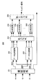
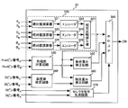
- FIG. 1 is a schematic block diagram showing a configuration of an image dividing apparatus according to an embodiment of the present invention.
- an image dividing device 10 according to an embodiment of the present invention includes a pixel value detecting circuit 1, a connection weight determining circuit 2, and an image dividing circuit 3.
- the pixel value detection circuit 1 receives an input image of one frame, detects an R component, a G component, and a B component of each pixel of the received input image, and converts the detected R component, G component, and B component into RGB values. Is output to the connection weight determination circuit 2.
- connection weight determination circuit 2 receives RGB values from the pixel value detection circuit 1, and determines connection weights between the pixels in a plurality of pixels constituting one frame based on the received RGB values by a method described later. Then, the determined combination weight is output to the image dividing circuit 3.
- the image dividing circuit 3 receives an input image from the outside and receives a connection weight from the connection weight determination circuit 2. Then, the image dividing circuit 3 divides the input image composed of one frame into the images of the respective objects by the region growing type image dividing method using the received connection weight.
- this region growing type image dividing method for example, a leader cell is determined from 3 ⁇ 3 pixels, and a region is grown from the determined leader cell region to a surrounding pixel region having a relatively large coupling weight. Is a method of dividing the image by repeating until no leader cell exists.
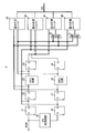
- FIG. 2 is a schematic diagram showing the configuration of the connection weight determination circuit 2 shown in FIG.
- the coupling weight determination circuit 2 includes D latch circuits 21, 22, 24, 26, 27, 29, FIFO circuits 23, 28, an HS conversion circuit 25, selectors 30, 31, And weight calculation units 32 to 35.
- the D latch circuit 21 receives the RGB value from the pixel value detection circuit 1, latches the received RGB value, and outputs the latched RGB value to the D latch circuit 22 and the weight calculation units 33 and 35.
- the D latch circuit 22 receives the RGB value from the D latch circuit 21, latches the received RGB value, and outputs the latched RGB value to the FIFO circuit 23, the weight calculation unit 32, and the selectors 30 and 31.
- the FIFO circuit 23 receives the RGB value from the D latch circuit 22, holds the received RGB value for one clock, and then outputs the RGB value to the D latch circuit 24, the weight calculation unit 32, and the selectors 30, 31. To do.
- the D latch circuit 24 latches the RGB value received from the FIFO circuit 23 and outputs the latched RGB value to the weight calculation units 33 and 34.
- the HS conversion circuit 25 receives the RGB values from the pixel value detection circuit 1 and converts the received RGB values into hue and saturation by a method described later. Then, the HS conversion circuit 25 outputs the converted hue and saturation to the D latch circuit 26.
- the D latch circuit 26 receives the hue and saturation from the HS conversion circuit 25, latches the received hue and saturation, and outputs the latched hue and saturation to the D latch circuit 27 and the weight calculation units 33 and 35. To do.
- the D latch circuit 27 receives the hue and saturation from the D latch circuit 26, latches the received hue and saturation, and uses the latched hue and saturation as the FIFO circuit 28, the weight calculation unit 32, and the selector 30, To 31.
- the FIFO circuit 28 receives the hue and saturation from the D latch circuit 27, holds the received hue and saturation for one clock, and then stores the hue and saturation in the D latch circuit 29, the weight calculation unit 32, and the selection. To the devices 30 and 31.
- the D latch circuit 29 receives the hue and saturation from the FIFO circuit 28, latches the received hue and saturation, and outputs the latched hue and saturation to the weight calculation units 33 and 34.
- the selector 30 receives RGB values from the D latch circuit 22 and the FIFO circuit 23 and receives hue and saturation from the D latch circuit 27 and the FIFO circuit 28. Then, the selector 30 selects the RGB value received from the FIFO circuit 23 and the hue and saturation received from the FIFO circuit 28 and outputs them to the weight calculation unit 34.
- the selector 31 receives RGB values from the D latch circuit 22 and the FIFO circuit 23 and receives hue and saturation from the D latch circuit 27 and the FIFO circuit 28. The selector 31 selects the RGB value received from the D latch circuit 22 and the hue and saturation received from the D latch circuit 27 and outputs them to the weight calculation unit 35.
- the selector 31 selects the FIFO circuit 23.
- the RGB values received from, and the hue and saturation received from the FIFO circuit 28 are selected and output to the weight calculation unit 35.
- the weight calculation unit 32 receives RGB values from the D latch circuit 22 and the FIFO circuit 23 and receives hue and saturation from the D latch circuit 27 and the FIFO circuit 28. Then, the weight calculation unit 32 uses the RGB value received from the D latch circuit 22 and the hue and saturation received from the D latch circuit 27 as the RGB value, hue and saturation (RGB3, HS3) corresponding to one pixel GE3. Let the RGB value received from the FIFO circuit 23 and the hue and saturation received from the FIFO circuit 28 be the RGB value, hue and saturation (RGB2, HS2) corresponding to another pixel GE2.
- the weight calculation unit 32 performs the pixel GE2 and the pixel GE3 on the basis of the RGB value, the hue and the saturation (RGB3, HS3), and the pixel GE2 and the pixel GE3 by a method described later based on the RGB value, the hue and the saturation (RGB2, HS2). Is calculated, and the calculated connection weight is output to the image dividing circuit 3.
- the weight calculation unit 33 receives RGB values from the D latch circuits 21 and 24 and receives hue and saturation from the D latch circuits 26 and 29. Then, the weight calculation unit 33 uses the RGB value received from the D latch circuit 21 and the hue and saturation received from the D latch circuit 26 as the RGB value, hue and saturation (RGB4, HS4) corresponding to one pixel GE4. The RGB value received from the D latch circuit 24 and the hue and saturation received from the D latch circuit 29 are set as the RGB value, hue and saturation (RGB1, HS1) corresponding to another pixel GE1.
- the weight calculation unit 33 performs the pixel GE1 and the pixel GE4 on the basis of the RGB value, the hue and the saturation (RGB4, HS4) and the RGB value, the hue and the saturation (RGB1, HS1) by a method described later. Is calculated, and the calculated connection weight is output to the image dividing circuit 3.
- the weight calculation unit 34 receives RGB values from the D latch circuit 24, receives hue and saturation from the D latch circuit 29, and receives RGB values, hue and saturation from the selector 30. Then, the weight calculation unit 34 uses the RGB value received from the D latch circuit 24 and the hue and saturation received from the D latch circuit 29 as the RGB value, hue and saturation (RGB1, HS1) corresponding to one pixel GE1.
- the RGB value, hue, and saturation received from the selector 30 are the RGB value, hue, and saturation (RGB2, HS2) corresponding to another pixel GE2.
- the weight calculation unit 34 uses the RGB value, hue, and saturation (RGB1, HS1) and the RGB value, hue, and saturation (RGB2, HS2) to perform the pixel GE1 and the pixel GE2 according to the method described later. Is calculated, and the calculated connection weight is output to the image dividing circuit 3.
- the weight calculation unit 35 receives RGB values from the D latch circuit 21, receives hue and saturation from the D latch circuit 26, and receives RGB values, hue and saturation from the selector 31. Then, the weight calculation unit 35 uses the RGB value received from the D latch circuit 21 and the hue and saturation received from the D latch circuit 26 as RGB values corresponding to one pixel GE4, hue and saturation (RGB4, HS4).
- the RGB value, hue, and saturation received from the selector 31 are the RGB value, hue, and saturation (RGB3, HS3) corresponding to another pixel GE3.
- the weight calculation unit 35 performs the pixel GE3 and the pixel GE4 on the basis of the RGB value, hue and saturation (RGB4, HS4) and the RGB value, hue and saturation (RGB3, HS3) by a method described later. Is calculated, and the calculated connection weight is output to the image dividing circuit 3.
- FIG. 3 is a conceptual diagram when the connection weight determination circuit 2 shown in FIG. 2 determines connection weights.
- FIG. 4 is another conceptual diagram when the connection weight determination circuit 2 shown in FIG. 2 determines connection weights.
- the connection weight determination circuit 2 determines connection weights in the pixels GE1 to GE4 arranged in 2 rows and 2 columns in one cycle.
- the weight calculation unit 32 receives the RGB value RGB2 of the pixel GE2 from the FIFO circuit 23, and the hue of the pixel GE2 from the FIFO circuit 28.
- the RGB value RGB3 of the pixel GE3 is received from the D latch circuit 22, and the hue and saturation HS3 of the pixel GE3 are received from the D latch circuit 27.
- the weight calculation unit 33 receives the RGB value RGB1 of the pixel GE1 from the D latch circuit 24, receives the hue and saturation HS1 of the pixel GE1 from the D latch circuit 29, and receives the RGB value RGB4 of the pixel GE4 from the D latch circuit 21.
- the D latch circuit 26 receives the hue and saturation HS4 of the pixel GE4.
- the weight calculation unit 34 receives the RGB value RGB1 of the pixel GE1 from the D latch circuit 24, receives the hue and saturation HS1 of the pixel GE1 from the D latch circuit 29, and receives the RGB value RGB2 of the pixel GE2 from the selector 30; It receives the hue and saturation HS2 of the pixel GE2.
- the weight calculation unit 35 receives the RGB value RGB4 of the pixel GE4 from the D latch circuit 21, receives the hue and saturation HS4 of the pixel GE4 from the D latch circuit 26, and receives the RGB value RGB3 of the pixel GE3 from the selector 31. It receives the hue and saturation HS3 of the pixel GE3.
- the weight calculation units 32 to 35 synchronize the RGB values, hues and saturations of the pixels GE2 and GE3, the RGB values, hues and saturations of the pixels GE1 and GE4, and the RGB values of the pixels GE1 and GE2, respectively. Receives hue and saturation and RGB values, hue and saturation of pixels GE3 and GE4. Then, the weight calculation unit 32 determines and outputs the coupling weight between the pixel GE2 and the pixel GE3, and the weight calculation unit 33 determines and outputs the coupling weight between the pixel GE1 and the pixel GE4, and the weight calculation unit 34. Determines and outputs the coupling weight between the pixel GE1 and the pixel GE2, and the weight calculation unit 35 determines and outputs the coupling weight between the pixel GE3 and the pixel GE4.
- the weight calculation units 32 to 35 determine and output the four connection weights shown in FIG. 3 in one cycle.
- the weight calculation unit 32 to 35 determines and outputs the four connection weights shown in FIG. 4 in one cycle.
- connection weight determination circuit 2 uses the RGB values, hues, and saturations of the four pixels arranged in 2 rows and 2 columns, and the 4 pixels arranged in 2 rows and 2 columns in one cycle. Determine the four connection weights in between.
- connection weight determination circuit 2 determines the connection weight between two pixels using the RGB value, hue, and saturation of each pixel, and the reason will be described below.
- RGB values hue and saturation are used in order to determine the connection weight between pixels, in addition to the RGB color space, hue (H: Hue), saturation (S: Saturation). ) And luminance (V: Value) is introduced.
- the hue (H) is an element representing a color type such as R, G, B, and the like.
- the saturation (S) is an element representing the vividness of the color, and is “0” for an achromatic color (black-gray-white).
- luminance (V) is an element representing brightness.
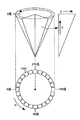
- FIG. 5 is a conceptual diagram of the HSV color space.
- the HSV color space has a conical shape.
- the hue (H) is drawn on an annular CRC at the bottom of the conical shape, and is represented in the range of 0 degrees to 360 degrees.
- FIG. 5 shows a hue with red as a reference (0 degree), and red (255, 0, 0), green (0, 255, 0), and blue (0, 0, 0) in the RGB color space. 255) corresponds to a hue of 0 degrees, a hue of 120 degrees, and a hue of 240 degrees, respectively.
- S Saturation
- V luminance
- the achromatic color has no hue (H) and saturation (S).
- Equation (1) MAX represents the maximum value of the R value, G value, and B value, and MIN represents the minimum value of the R value, G value, and B value.
- hue (H) is not defined. This is when the R value, the G value, and the B value are all equal, and because it represents an achromatic color and is around the gray straight line at the center of the cone, the Hue value at that time has no meaning. .
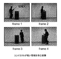
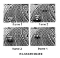
- FIG. 6 is a diagram illustrating an image used for image evaluation based on hue and saturation.
- FIG. 7 is a diagram showing another image used for image evaluation based on hue and saturation.
- FIG. 6 shows an image including an area with low contrast
- FIG. 7 shows an image including disturbance reflection
- FIG. 8 is a diagram showing a result of dividing the region X shown in FIG. 6 and a result of dividing the region Y shown in FIG.
- FIG. 9 is a diagram for explaining a problem in the conventional image division.
- connection weight W ij; kl between two pixels is calculated by the following equations (4) and (5) using only the RGB value of each pixel.
- connection weight W ij; kl a similarity between pixels
- the connection weight W ij; kl is obtained by substituting the three connection weights calculated for red, green, and blue using the equation (4) into the equation (5) to obtain the three weights for red, green, and blue.
- the connection weights the smallest one is determined as a connection weight W ij; kl between pixels.
- the combination weights using the RGB color space do not consider the color of the pixel.
- FIG. 9A is a graph showing an area having gradation change in units of pixels and a change in the combination weight of the gradation area when the horizontal axis is the x-axis and the vertical axis is the combination weight.
- connection weights are also equal. If the connection weight of neighboring pixels is equal to or greater than the threshold value ⁇ z used for region growth, the region continues to expand in the direction of the arrow.
- the sample image shown in FIG. 6 has a low contrast, a shadow is generated at the boundary due to the overlap between the desk and the human, a clear edge does not appear between the desk area and the person area, and the color smoothly changes between the two areas. This is a gradation image. Therefore, it is difficult to divide a desk and a person using the conventional image division method using an edge (see FIG. 8).
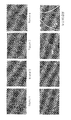
- FIG. 10 is a diagram showing an 8-bit gray image obtained by normalizing the values (0 to 360 degrees) converted from the RGB values of the sample image shown in FIG. .
- FIG. 11 is a diagram showing an 8-bit gray image obtained by normalizing the value (0 to 360 degrees) converted from the RGB value of the sample image shown in FIG. It is.
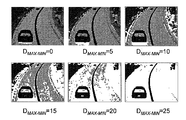
- the results of evaluating the influence on the image when the D MAX-MIN value is increased by “5” from “0” are the results shown in FIGS.
- FIG. 12 is a diagram in which the value (range 0 to 1) obtained by converting the RGB value of the sample image shown in FIG. 6 into the S value using Expression (2) is normalized to 256 gradations to obtain an 8-bit gray image. is there.
- FIG. 13 shows an 8-bit gray image obtained by normalizing the value (range 0 to 1) obtained by converting the RGB value of the sample image shown in FIG. 7 into the S value using Expression (2) to 256 gradations.
- FIG. 12 is a diagram in which the value (range 0 to 1) obtained by converting the RGB value of the sample image shown in FIG. 6 into the S value using Expression (2) is normalized to 256 gradations to obtain an 8-bit gray image. is there.
- FIG. 13 shows an 8-bit gray image obtained by normalizing the value (range 0 to 1) obtained by converting the RGB value of the sample image shown in FIG. 7 into the S value using Expression (2) to 256 gradations.
- FIG. 12 is a diagram in which the value (range 0 to 1) obtained by
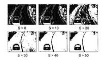
- FIG. 12 and FIG. 13 show the influence on the image when the saturation (S) as the threshold value is changed from 0 to 50 in increments of 10.
- the images shown in FIGS. 12 and 13 are binary with a pixel having a saturation (S) smaller than the threshold value as white (255) and a pixel having a saturation greater than the threshold value as black (0). This is a converted image.
- a pixel having a saturation (S) value smaller than 50 is treated as an achromatic color
- a pixel having a saturation (S) value of 50 or more is treated as a chromatic color. Good results were obtained regarding the discrimination from chromatic areas. Other sample images were also evaluated, but good results were obtained when the saturation threshold was set near 50.
- the HSV color space is not suitable for image segmentation of achromatic areas. This is because, as can be seen from FIG. 5, when the saturation is low, the hue can hardly be identified, and the Hue value has no meaning.
- the color weight between the RGB values and the HSV values is used to determine the connection weight between the pixels, and the color regions that each color space is not good at complement each other. is there.
- the HS conversion circuit 25 generally uses the expressions (1) and (2) to calculate the RGB. Convert values to Hue (H) and Saturation (S).
- each of R, G, and B is 8-bit data
- a large-capacity memory of ((2 8 ) 3 ⁇ 9) bits is necessary, and the circuit area of the decoder is increased. .
- the calculation result is limited to the number of bins by dividing H (0 to 360 degrees) and S (0 to 1) into a plurality of bins (regions), and then the table is displayed.
- the hue (H) and the saturation (S) are obtained by referring to them. According to this method, it is possible to realize a conversion circuit from RGB values to HSV values with a reduced circuit area without using any divider.
- FIG. 14 is a block diagram of a hue (Hue) bin.
- the hue (Hue) bin configuration includes a three-stage configuration, and a 360-degree Hue value is configured by 90 bins.
- MIN is determined, and it is determined whether the fractional part of the expression corresponding to the MAX condition is positive or negative from Expression (1).
- the fractional part is negative, it becomes “0”, and when the fractional part is positive, it becomes “1” (second stage).
- the pixel of interest corresponds to the third bin.
- MED represents any value of R, G, B other than MAX and MIN, that is, an intermediate value.
- the bin number is determined from the formation result (1,0) of the 14 inequalities generated when the value of X in the expression (7) is changed from 1 to 14.
- FIG. 15 is a schematic diagram showing a configuration of a hue conversion circuit included in the HS conversion circuit 25 shown in FIG.
- the HS conversion circuit 25 includes a hue conversion circuit 250 shown in FIG.
- hue conversion circuit 250 includes a determination circuit 251, data generation circuits 252 and 253, a switch 254, comparison circuits 255 to 268, and an encoder 269.
- the determination circuit 251 receives the RGB value of each pixel from the pixel value detection circuit 1, and determines the maximum value MAX, the minimum value MIN, and the intermediate value MED of the received RGB value. Then, the determination circuit 251 outputs the determined maximum value MAX to the data generation circuit 252, outputs the intermediate value MED to the data generation circuit 253, and outputs the minimum value MIN to the data generation circuits 252 and 253.
- the data generation circuit 253 receives the intermediate value MED and the minimum value MIN from the determination circuit 251 and calculates 15 ⁇ (MED ⁇ MIN) based on the received intermediate value MED and minimum value MIN. 15 ⁇ (MED-MIN) is output to the switch 254. That is, the data generation circuit 253 calculates A on the left side of Expression (7) and outputs the calculated A to the switch 254.
- the switch 254 outputs 1 ⁇ (MAX ⁇ MIN) and 15 ⁇ (MED ⁇ MIN) to the comparison circuit 255, and outputs 2 ⁇ (MAX ⁇ MIN) and 15 ⁇ (MED ⁇ MIN) to the comparison circuit 256. Thereafter, 14 ⁇ (MAX-MIN) and 15 ⁇ (MED-MIN) are output to the comparison circuit 268 in the same manner.
- the comparison circuit 255 receives 1 ⁇ (MAX-MIN) and 15 ⁇ (MED-MIN) from the switch 254, and compares 1 ⁇ (MAX-MIN) with 15 ⁇ (MED-MIN). Then, the comparison circuit 255 outputs the comparison result to the encoder 269. More specifically, the comparison circuit 255 outputs “1” to the encoder 269 when 15 ⁇ (MED ⁇ MIN) ⁇ 1 ⁇ (MAX ⁇ MIN) is established, and 15 ⁇ (MED ⁇ MIN) ⁇ 1. When x (MAX-MIN) is not established, “0” is output to the encoder 269.
- the comparison circuit 256 receives 2 ⁇ (MAX-MIN) and 15 ⁇ (MED-MIN) from the switch 254, and compares 2 ⁇ (MAX-MIN) with 15 ⁇ (MED-MIN). Then, the comparison circuit 256 outputs the comparison result (1 or 0) to the encoder 269.
- the comparison circuit 268 receives 14 ⁇ (MAX-MIN) and 15 ⁇ (MED-MIN) from the switch 254, and compares 14 ⁇ (MAX-MIN) with 15 ⁇ (MED-MIN). . Then, the comparison circuit 268 outputs the comparison result (1 or 0) to the encoder 269.
- the comparison circuits 255 to 268 compare X ⁇ (MAX-MIN) with 15 ⁇ (MED-MIN) in parallel, and output the comparison result to the encoder 269. Therefore, encoder 269 receives 14-bit data indicating the comparison result from comparison circuits 255-268.
- the encoder 269 receives the comparison result of 14 bits from the comparison circuits 255 to 268 and determines the bin number based on the received comparison result of 14 bits. More specifically, when the encoder 269 receives the comparison result of [01000000000000] from the comparison circuits 255 to 268, the encoder 269 determines the bin number as “2” and the comparison result of [000000000000] from the comparison circuits 255 to 268. When received, the bin number is determined to be “10”. The encoder 269 determines the bin number as “15” when receiving the comparison result of “00000000000000” consisting of all “0” from the comparison circuits 255-268.
- the encoder 269 outputs the determined bin number to the D latch circuit 26 as a hue bin number.
- each of the data generation circuits 252 and 253 is added. This can be realized by a simple circuit using a shifter and a shifter.
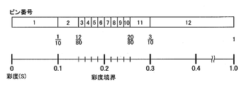
- FIG. 16 is a block diagram of a chroma (S) bin.
- saturation (S) in the range of 0 to 0.1 is assigned to 1 bin
- saturation (S) in the range of 0.1 to 0.15 is assigned to 2 bins.
- Saturation (S) in the range of 0.15 to 0.1625 is assigned to 3 bins
- Saturation (S) in the range of 0.1625 to 0.1750 is assigned to 4 bins.
- Saturation (S) in the range of 0.1750 to 0.1875 is assigned to 5 bins
- saturation (S) in the range of 0.1875 to 0.2 is assigned to 6 bins.
- saturation (S) in the range of 0.2 to 0.2125 is assigned to 7 bins
- saturation (S) in the range of 0.2125 to 0.2250 is assigned to 8 bins
- Saturation (S) in the range of 0.2250 to 0.2375 is assigned to 9 bins
- saturation (S) in the range of 0.2375 to 0.25 is assigned to 10 bins.
- Saturation (S) in the range of 25 to 0.30 is assigned to 11 bins
- saturation (S) in the range of 0.3 to 1.0 is assigned to 12 bins.
- the saturation (S) is assigned to a subdivided bin as it is near 0.2 which is the saturation boundary.
- the conversion from RGB values to saturation (S) uses the same method as the conversion from RGB values to hue (H).
- Equation (10) and Equation (11) are obtained, respectively.
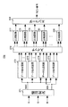
- FIG. 17 is a schematic diagram showing a configuration of a saturation conversion circuit included in the HS conversion circuit 25 shown in FIG.
- the HS conversion circuit 25 includes a saturation conversion circuit 270 shown in FIG.
- saturation conversion circuit 270 includes a determination circuit 271, data generation circuits 272 to 275, a switch 276, comparison circuits 277 to 288, and an encoder 289.
- the determination circuit 271 receives the RGB values from the pixel value detection circuit 1, and determines the maximum value MAX and the minimum value MIN of the received RGB values. Then, the determination circuit 271 outputs the determined maximum value MAX to the data generation circuits 272 to 275, and outputs the determined minimum value MIN to the data generation circuits 274 and 275.
- the data generation circuit 274 receives the maximum value MAX and the minimum value MIN from the determination circuit 271, calculates 20 ⁇ (MAX ⁇ MIN) using the received maximum value MAX and minimum value MIN, and calculates the calculated 20 ⁇ ( MAX-MIN) is output to the switch 276. That is, the data generation circuit 274 calculates C on the left side of Equation (10) and outputs the calculated C to the switch 276.
- the data generation circuit 275 receives the maximum value MAX and the minimum value MIN from the decision circuit 271, calculates 80 ⁇ (MAX ⁇ MIN) using the received maximum value MAX and minimum value MIN, and calculates the calculated 80 ⁇ ( MAX-MIN) is output to the switch 276. That is, the data generation circuit 275 calculates E on the left side of Equation (11) and outputs the calculated E to the switch 276.
- the switch 276 outputs 2 ⁇ MAX and 20 ⁇ (MAX ⁇ MIN) to the comparison circuit 277, outputs 3 ⁇ MAX and 20 ⁇ (MAX ⁇ MIN) to the comparison circuit 278, and outputs 6 ⁇ MAX and 20 ⁇ . (MAX-MIN) is output to the comparison circuit 279.
- the switch 276 outputs 12 ⁇ MAX and 80 ⁇ (MAX ⁇ MIN) to the comparison circuit 280, and outputs 13 ⁇ MAX and 80 ⁇ (MAX ⁇ MIN) to the comparison circuit 281. 20 ⁇ MAX and 80 ⁇ (MAX ⁇ MIN) are output to the comparison circuit 288.
- the comparison circuit 277 receives 2 ⁇ MAX and 20 ⁇ (MAX-MIN) from the switch 276, compares 2 ⁇ MAX with 20 ⁇ (MAX-MIN), and outputs the comparison result to the encoder 289. More specifically, the comparison circuit 277 outputs “1” to the encoder 289 when 20 ⁇ (MAX ⁇ MIN) ⁇ 2 ⁇ MAX is satisfied, and 20 ⁇ (MAX ⁇ MIN) ⁇ 2 ⁇ MAX is satisfied. When not, “0” is output to the encoder 289.
- the comparison circuit 278 receives 3 ⁇ MAX and 20 ⁇ (MAX ⁇ MIN) from the switch 276, compares 3 ⁇ MAX with 20 ⁇ (MAX ⁇ MIN), and 20 ⁇ (MAX ⁇ MIN) ⁇ 3 ⁇ MAX. When “1” is satisfied, “1” is output to the encoder 289, and when 20 ⁇ (MAX ⁇ MIN) ⁇ 3 ⁇ MAX is not satisfied, “0” is output to the encoder 289.
- the comparison circuit 279 receives 6 ⁇ MAX and 20 ⁇ (MAX ⁇ MIN) from the switch 276, compares 6 ⁇ MAX with 20 ⁇ (MAX ⁇ MIN), and 20 ⁇ (MAX ⁇ MIN) ⁇ 6. When ⁇ MAX is satisfied, “1” is output to the encoder 289, and when 20 ⁇ (MAX ⁇ MIN) ⁇ 6 ⁇ MAX is not satisfied, “0” is output to the encoder 289.
- the comparison circuit 280 receives 12 ⁇ MAX and 80 ⁇ (MAX ⁇ MIN) from the switch 276, compares 12 ⁇ AMX with 80 ⁇ (MAX ⁇ MIN), and outputs the comparison result to the encoder 289. More specifically, the comparison circuit 280 outputs “1” to the encoder 289 when 80 ⁇ (MAX ⁇ MIN) ⁇ 12 ⁇ MAX is established, and 80 ⁇ (MAX ⁇ MIN) ⁇ 12 ⁇ MAX is established. When not, “0” is output to the encoder 289.
- the comparison circuit 281 receives 13 ⁇ MAX and 80 ⁇ (MAX ⁇ MIN) from the switch 276, compares 13 ⁇ AMX with 80 ⁇ (MAX ⁇ MIN), and 80 ⁇ (MAX ⁇ MIN) ⁇ 13 ⁇ MAX is established. “1” is output to the encoder 289, and “0” is output to the encoder 289 when 80 ⁇ (MAX ⁇ MIN) ⁇ 13 ⁇ MAX is not satisfied.
- the comparison circuit 288 receives 20 ⁇ MAX and 80 ⁇ (MAX ⁇ MIN) from the switch 276, compares 20 ⁇ AMX with 80 ⁇ (MAX ⁇ MIN), and 80 ⁇ (MAX ⁇ MIN). When ⁇ 20 ⁇ MAX is satisfied, “1” is output to the encoder 289, and when 80 ⁇ (MAX ⁇ MIN) ⁇ 20 ⁇ MAX is not satisfied, “0” is output to the encoder 289.
- comparison circuits 277 to 288 perform the above-described comparison in parallel, and output the comparison result to the encoder 289 in parallel. Therefore, encoder 289 receives 12-bit data from comparison circuits 277-288.
- the encoder 289 receives the comparison result of 12 bits from the comparison circuits 277 to 288, and determines the bin number based on the received comparison result of 12 bits. More specifically, when the encoder 289 receives the comparison result of [100000000000000] from the comparison circuits 277 to 288, the encoder 289 determines the bin number as “1” and the comparison result of [00000010000000] from the comparison circuits 277 to 288. When received, the bin number is determined to be “7”. The encoder 289 determines the bin number in the same manner when receiving the other 12-bit comparison results.
- the encoder 289 outputs the determined bin number to the D latch circuit 26 as the S bin number.
- the data generation circuit 272 calculates Y ⁇ MAX
- the data generation circuit 273 calculates Z ⁇ MAX
- the data generation circuit 274 calculates 20 ⁇ (MAX ⁇ MIN) to generate data. Since the circuit 275 calculates 80 ⁇ (MAX ⁇ MIN), each of the data generation circuits 272 to 275 can be realized by a simple circuit using an adder and a shifter.
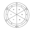
- FIG. 18 is a diagram for explaining a method of determining the connection weight.
- the outer circle represents a hue (Hue), and takes saturation from the center in the circumferential direction.
- a threshold value Sth of about 0.2 is suitable for separating a color region and a color close to an achromatic color whose hue can hardly be identified, 0.2 is defined as a saturation boundary.
- the inner circle represents the boundary where the saturation is 0.2, the region where the saturation is lower than 0.2 is a color almost achromatic, and the region where the saturation is higher than 0.2 is Treat as a chromatic color.
- x in the figure represents a pixel.
- both of the two saturations S1 and S2 are equal to or smaller than the threshold value Sth, it is determined that the two pixels belong to the achromatic color region (in the case of FIG. 18A), and based on only the RGB value.
- the connection weight between the two pixels is determined using equations (4) and (5).
- the connection weight between the two pixels is determined using the RGB value and the saturation (S).
- both of the two saturations S1 and S2 are larger than the threshold value Sth, it is determined that both of the two pixels belong to the chromatic color region (in the case of (c) in FIG. 18), and the RGB value and the hue are determined. (H) is used to determine the connection weight between the two pixels.
- the leader cell is found in the person area of the sample image shown in FIG. 6, the area has grown in the desk area, and the area has expanded from the achromatic area to the color area.
- the color region may grow from the achromatic region.
- the division is difficult only with the RGB values.
- the boundary between the achromatic color region and the chromatic color region is determined using the saturation (S), and the connection between the two pixels belonging to the boundary surface
- S saturation
- the combination weight in the direction of suppressing the growth of the region from the chromatic color region to the achromatic color region or from the achromatic color region to the chromatic color region.
- the image division the growth of the region from the chromatic color region to the achromatic color region or from the achromatic color region to the chromatic color region is suppressed, and the image can be accurately divided even for an input image with low contrast.
- the hue determination using the hue (H) is taken in.
- determining the connection weight between pixels belonging to the chromatic color region first, the hue comparison between two pixels is performed, and whether or not the difference in hue is within a certain threshold value, that is, the two pixels have the same hue. Judgment is made as to whether or not the range is acceptable. Then, when it is determined that the hues are the same, when the combination weight determined from the RGB values is small (that is, when the difference is large in the RGB color space due to the influence of reflection or the like), the larger combination is performed in the direction of promoting the region. Give weight. Thereby, the pixels of the chromatic color region belonging to the similar hue are easily grown, and the regions where the luminance and saturation change due to reflection or the like can be extracted as one region.
- connection weight is determined using only the RGB values according to the expressions (4) and (5), but the connection weight is calculated using the expressions (4) and (5).
- the connection weight is determined by table mapping using a decoder. Table 1 shows a conversion table when determining the connection weight using only RGB values.
- the conversion table shown in Table 1 shows the difference between the luminance I i, j and the luminance I k, l calculated using the RGB values of the two pixels of the target pixel (i, j) and the neighboring pixel (k, l).
- and the connection weight is shown.
- connection weight smaller than the connection weight obtained from the RGB color space using the conversion table of Table 1 is given in order to prevent the area from spreading.
- the connection weight between pixels near the saturation boundary and the saturation boundary are completely eliminated.
- the connection weight is determined so that the connection weight between the pixels having completely different saturations is not treated on the same basis.
- FIG. 19 is a diagram illustrating the influence of the reflection on the pixel value.
- FIG. 20 is a diagram illustrating a change in the achromatic pixel value when the saturation boundary is changed.
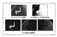
- FIG. 19A shows the input image
- An image binarized into a chromatic color (0) and a chromatic color (1) is shown
- FIG. 19C shows a result of image division.
- the same area is divided into a chromatic color area and an achromatic color area at the center of the image.
- FIG. 19C the road is suppressed from growing at the saturation boundary, and the accuracy of the divided image is lower than when the RGB color space is used.
- a curve k1 indicates a change in the number of achromatic pixels for an image including a color area in the image
- a curve k2 indicates a change in the number of achromatic pixels for a gray image not including the color area in the image. Indicates.
- the reduction amount of the connection weight is reduced, and the reduction amount of the connection weight is increased as the distance from the saturation boundary is increased. Thereby, the division accuracy of the gray area can be improved.
- Table 2 shows a conversion table of connection weights in the case shown in FIG.
- is 001x_xxxx, 0000_1xxx, 0000_01xx, 0000_001x, if a 0000_000X, binding weights, chroma difference
- connection weight in the case shown in FIG. 18C will be described. It has been found that, in a color image, when there is no influence of reflection or the like, a highly accurate region division result can be obtained by determining the connection weight using the RGB color space. Therefore, it is preferable to optimize the coupling weight using the HSV color space only for the coupling weight between pixels affected by reflection.
- FIG. 21 is a diagram illustrating the influence of irregular reflection of R, G, and B components.
- FIG. 21A shows a sample image used for the evaluation
- FIG. 21B shows the R, G, B values of the pixels on the line segment AB shown in FIG. 21A
- FIG. 21 (c) shows changes in the R, G, B values of the pixels on the line segment CD shown in FIG. 21 (a). That is, (b) of FIG. 21 shows a change in the pixel value of the vehicle body region affected by light reflection, and (c) of FIG. 21 shows a pixel in the road region not affected by light reflection. Indicates a change in value.
- the body region has a larger change in pixel value between consecutive pixels than the road region. Then, it was found from the sample image having the reflection area that the amount of change between the pixels due to the reflection of light is concentrated between 30 and 100. That is, it is determined that an area where the pixel value difference is very small, or conversely, an area where the pixel value difference is very large is not affected by light reflection.
- the optimization of the coupling weight using the evaluation result of the hue (H) is limited to 01xxx_xxxx, 001x_xxxx, 0001_xxxx shown in Table 1, thereby maintaining the division accuracy of the color area based on the RGB values.
- the accuracy can be improved by the hue (H).
- FIG. 22 is a diagram showing a histogram of the Hue value of the red car body.
- FIG. 23 is a diagram showing a histogram of Hue values for the body of a blue car.
- is 4 degrees or less, 5 degrees or more and 8 degrees or less, and the other three determination conditions.
- Table 3 the connection weight conversion table in the case shown in FIG.
- FIG. 24 is a block diagram of the weight calculation unit 32 shown in FIG. Referring to FIG. 24, the weight calculation unit 32 includes a combination weight calculation circuit 320, a hue difference calculation circuit 330, a saturation difference calculation circuit 340, combination weight correction circuits 350 and 360, and a selector signal generation circuit 370. , And selector 380.
- connection weight calculation circuit 320 calculates a connection weight between the two pixels using Table 1, and uses the calculated connection weight as the connection weight.
- the data is output to the correction circuits 350 and 360 and the selector 380.
- the combination weight calculation circuit 320 includes absolute value calculators 321, 323, 325, encoders 322, 324, 326, and a minimum value selection circuit 327.
- the absolute value calculator 321 calculates the luminances I A (R) and I B (R) based on the two R values R A and R B received from the D latch circuit 22 and the FIFO circuit 23, and calculates luminance I a (R), the absolute value of the difference between I B (R)
- the encoder 322 holds Table 1, and upon receiving the absolute value
- the absolute value calculator 323 calculates the luminances I A (G) and I B (G) based on the two G values G A and G B received from the D latch circuit 22 and the FIFO circuit 23, and calculates luminance I a (G), the absolute value of the difference between I B (G)
- the encoder 324 holds Table 1, and upon receiving the absolute value
- the absolute value calculator 325 calculates the luminances I A (B) and I B (B) based on the two B values B A and B B received from the D latch circuit 22 and the FIFO circuit 23, and calculates The absolute value
- the encoder 326 holds Table 1, and upon receiving the absolute value
- the minimum value selection circuit 327 receives the combination weights WA , B (R), WA , B (G), WA , B (B) from the encoders 322, 324, 326, respectively, and receives the three combinations received.
- the minimum connection weight WA , B is selected from the weights WA , B (R), WA , B (G), WA , B (B). Then, the minimum value selection circuit 327, and outputs the selected connection weight W A, a B to connection weight correction circuit 350, 360 and a selector 380.
- the hue difference calculation circuit 330 holds the assignment map of the hue bin numbers shown in FIG. 14 and receives the hue bin number A and the hue bin number B from the D latch circuit 27 and the FIFO circuit 28, respectively.
- the hue difference calculation circuit 330 refers to the assignment diagram of Hue bin number shown in FIG. 14, Hue values H A corresponding to the received Hue bin number A and Hue bin number B, and detects the H B. Then, the hue difference calculation circuit 330, the hue difference
- the saturation difference calculation circuit 340 holds the S bin number assignment diagram shown in FIG. 16, and receives the S bin number A and the S bin number B from the D latch circuit 27 and the FIFO circuit 28, respectively. Then, the saturation difference calculation circuit 340 detects the S values S A and S B corresponding to the received S bin number A and S bin number B with reference to the S bin number assignment diagram shown in FIG. . Then, chroma difference calculation circuit 340, a chroma difference
- the combination weight correction circuit 350 holds Table 3, receives the combination weights WA and B from the combination weight calculation circuit 320 , and receives the hue difference
- connection weight W a corresponding to 0000_000X, extracting B _H from Table 3, and outputs the extracted connection weight W a, the B _H to the selector 380.
- the connection weight correction circuit 350 determines whether or not the hue difference
- connection weight correction circuit 350 the hue difference
- if is not less than "4", the connection weight W A consisting of 4, extracts the B _H from Table 3, the extracted connection weight W A outputs B _H a ( 4) to the selector 380.
- the connection weight correction circuit 350 determines whether or not the hue difference
- if is equal to or less than "4", the connection weight W a of 32, extracts the B _H from Table 3, the extracted connection weight W a, B _H ( 32) is output to the selector 380. On the other hand, when the hue difference
- the connection weight correction circuit 350 the hue difference
- if is not less than "8”, the connection weight W A of 8, then extracted B _H from Table 3, the connection weight W A which the extracted outputs B _H a ( 8) to the selector 380.
- the connection weight correction circuit 350 determines whether the hue difference
- if is equal to or less than "4", the connection weight W a of 32, extracts the B _H from Table 3, the extracted connection weight W a, B _H ( 32) is output to the selector 380.
- connection weight modification circuitry 350 is hue difference
- if is not less than "4", the connection weight W A of 16, extracts the B _H from Table 3, the connection weight W A which the extracted , B_H ( 16) to the selector 380.
- the combination weight correction circuit 360 holds Table 2 and receives the combination weights WA and B from the combination weight calculation circuit 320 and the saturation difference
- connection weight correction circuit 360 a chroma difference
- connection weight W a the absolute value matches the B
- the connection weight correction circuit 360 further determines whether or not the saturation difference
- the connection weights WA , B_S to be extracted are extracted from Table 2, and the extracted connection weights WA , B_S are output to the selector 380.
- the connection weight correction circuit 360 further determines whether or not the saturation difference
- the connection weights WA , B_S to be extracted are extracted from Table 2, and the extracted connection weights WA , B_S are output to the selector 380.
- connection weight correction circuit 360 determines the absolute value
- connection weight W a which correspond to and to extract B _S from Table 2, and outputs the extracted connection weight W a, the B _S to the selector 380.
- selector signal generation circuit 370 compares the two detected S values S A and S B with threshold value Sth.
- the selector signal generating circuit 370 two S values S A, when both S B is less than or equal to the threshold Sth, the connection weight W A received from the connection weight computing circuit 320, a selector for selecting the B A signal SEL_RGB is generated, and the generated selector signal SEL_RGB is output to the selector 380.
- the selector signal generation circuit 370 selects the combination weight WA , B_S received from the combination weight correction circuit 360 when one of the two S values S A and S B is equal to or less than the threshold value Sth. Selector signal SEL_S is generated, and the generated selector signal SEL_S is output to the selector 380.
- the selector signal generator circuit 370 includes two S values S A, when both S B is greater than the threshold value Sth, the connection weight W A received from the connection weight correction circuit 350, for selecting the B _H A selector signal SEL_H is generated, and the generated selector signal SEL_H is output to the selector 380.
- the selector 380, the connection weight W A from the connection weight calculation circuit 320 receives the B, and from the connection weight correction circuit 350 and 360 connection weights W A, B _H, W A, receiving the B _S.
- the selector 380 when the selector signal generating circuit 370 receives the selector signal SEL_RGB, select the connection weight W A, B, and outputs the selected connection weight W A, B as connection weight CW.
- the selector 380 when the selector signal generating circuit 370 receives the selector signal SEL_S, connection weight W A, select B _S, and outputs the selected connection weight W A, the B _S as connection weight CW.
- the selector 380, the selector signal generator circuit 370 receives a selector signal SEL_H, connection weight W A, select B _H, and outputs the selected connection weight W A, the B _H as connection weight CW.
- Weight calculating unit 2 33 is made of the same configuration as the weight calculating unit 32 shown in FIG. 24, RGB values RGB A received from the D latch circuit 21, 24, and RGB B, received from the D latch circuit 26 and 29 and Hue bin number a, Hue bin number B, and based on the S bin number a, and S bin number B, in the same manner as weight calculating unit 32, the connection weight W a, B, W a, B _H, W a, calculates the B _S, the computed connection weight W a, B, W a, B _H, W a, selects and outputs one of B _S as connection weight CW.
- connection weight W a, B, W a , B _H, W a calculates the B _S, the computed connection weight W a, B, W a, B _H, W a, selects and outputs one of B _S as connection weight CW.
- the weight calculation unit 35 shown in FIG. 2 has the same configuration as that of the weight calculation unit 32 shown in FIG. 24, and the RGB value RGB A received from the D latch circuit 21 and the Hue bin number A received from the D latch circuit 26. a and S bin number a, RGB value RGB B received from the selector 31, based on the Hue bin number B and S bin number B, in the same manner as weight calculating unit 32, the connection weight W a, B, W a , B _H, W a, calculates the B _S, the computed connection weight W a, B, W a, B _H, W a, selects and outputs one of B _S as connection weight CW.
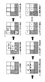
- FIG. 25 is a diagram for explaining an image dividing method.
- the image dividing circuit 3 divides one frame into images of each object by a region growing type image dividing method.
- This region-growing image segmentation method is the LEGION model (D.DL. Wang, angand D. Terman, “Image segmentation based on oscillator correlation,” Neural Computation, Volume 9 (4), pp. 805-836 (1997). ) Is handled in four states: self-ignition (self-excitable), self-ignitable (excitable), and ignition (inhibition).
- This region-growing image segmentation method includes four steps of initialization, self-ignition, ignition, and suppression.
- the image dividing circuit 3 receives an input image having a 3 ⁇ 3 configuration shown in FIG. Then, the image dividing circuit 3 receives eight coupling weights CW1 to CW8 between the pixels in the nine pixels constituting the input image from the coupling weight determination circuit 2, and receives the received eight coupling weights CW1 to CW8. Each pixel is stored in the memory in association with each other. In FIG. 25B, eight connection weights of the pixel (2, 2) and the surrounding pixels are shown.
- the image dividing circuit 3 reads the eight connection weights CW1 to CW8 held in the memory, and calculates the sum SUM (CW) of the read eight connection weights CW1 to CW8.
- the image dividing circuit 3 determines whether or not the calculated sum SUM (CW) is larger than the threshold value phi P for determining the leader cell.
- SUM means calculating a sum represented by a sigma symbol in mathematics.
- the image dividing circuit 3 executes this processing by setting each of the nine pixels of the input image as a pixel that is the center of calculation of the coupling weight, and determines a leader cell (see (c) of FIG. 25).
- the image dividing circuit 3 When the extinguishing process is completed, the image dividing circuit 3 returns to the self-igniting process for dividing the next area again. Then, the image dividing circuit 3 repeatedly executes the above-described processing until no leader cell exists, and divides each area. Then, after all the reader cells are ignited, the image dividing circuit 3 labels all the areas and ends the division of the image of one frame (see (h) in FIG. 25).
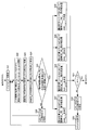
- FIG. 26 is a flowchart for explaining an image dividing method according to the present invention.
- the pixel value detection circuit 1 causes each pixel GE ij (1 ⁇ i ⁇ n) of the input image made up of n ⁇ n (n is an integer of 2 or more).
- 1 ⁇ j ⁇ n) RGB value RGB ij (1 ⁇ i ⁇ n, 1 ⁇ j ⁇ n) is detected (step S 1), and the detected RGB value RGB ij of each pixel is sent to the connection weight determination circuit 2.
- Output when a series of operations is started, the pixel value detection circuit 1 causes each pixel GE ij (1 ⁇ i ⁇ n) of the input image made up of n ⁇ n (n is an integer of 2 or more).
- the connection weight determination circuit 2 receives the RGB value RGB ij (1 ⁇ i ⁇ n, 1 ⁇ j ⁇ n) of each pixel GE ij (1 ⁇ i ⁇ n, 1 ⁇ j ⁇ n) from the pixel value detection circuit 1.
- the RGB values RGB ij (1 ⁇ i ⁇ n, 1 ⁇ j ⁇ n) of the received pixels GE ij (1 ⁇ i ⁇ n, 1 ⁇ j ⁇ n) are converted into hues H ij (1 ⁇ 1) by the method described above.
- connection weight W ij between the pixels ; kl (1 ⁇ i ⁇ n, 1 ⁇ j ⁇ n, 1 ⁇ k ⁇ n, 1 ⁇ l ⁇ n) are determined (step S2).
- connection weight determination circuit 2 divides the determined connection weight W ij; kl (1 ⁇ i ⁇ n, 1 ⁇ j ⁇ n, 1 ⁇ k ⁇ n, 1 ⁇ l ⁇ n) between the determined pixels. Output to circuit 3.
- the image dividing circuit 3 receives an input image from the outside, and the connection weight W ij between the pixels from the connection weight determination circuit 2 ; kl (1 ⁇ i ⁇ n, 1 ⁇ j ⁇ n, 1 ⁇ k ⁇ n, 1 ⁇ l ⁇ n). Then, the image dividing circuit 3 uses the received connection weight W ij; kl (1 ⁇ i ⁇ n, 1 ⁇ j ⁇ n, 1 ⁇ k ⁇ n, 1 ⁇ l ⁇ n). The frame image is divided (step S3). And a series of operation
- FIG. 27 is a flowchart for explaining the detailed operation of step S2 shown in FIG. 27, pixel GE1 shown in FIG. 3 is pixel GE ij , pixel GE2 is pixel GE kl , pixel GE3 is pixel GE i + 1, j , pixel GE4 is pixel GE k + 1, l , and details of step S2 The operation will be described.
- the connection weight determination circuit 2 outputs a plurality of pixels GE ij (1 ⁇ i ⁇ n, 1 ⁇ j ⁇ n) from the pixel value detection circuit 1.
- the RGB values RGB ij (1 ⁇ i ⁇ n, 1 ⁇ j ⁇ n) are sequentially received.
- connection weight determination circuit 2 includes two adjacent pixels GE ij sequentially input from the pixel value detection circuit 1 among the plurality of pixels GE ij (1 ⁇ i ⁇ n, 1 ⁇ j ⁇ n) of the input image. , GE kl (1 ⁇ k ⁇ n, 1 ⁇ l ⁇ n) is selected (step S22).
- the combination weight determination circuit 2 converts the RGB value RGB ij of the pixel GE ij into the hue H ij and the saturation S ij by the above-described method by the HS conversion circuit 25 (Step S23), and the RGB value of the pixel GE kl .
- RGB kl is converted into hue H kl and saturation S kl by the above-described method (step S24).
- the RGB values of four sets of adjacent pixels GE ij , GE kl ; GE i + 1, j , GE kl ; GE ij , GE k + 1, l ; GE i + 1, j , GE k + 1, l are hues It is then determined whether or not it has been converted to saturation (step S25).
- step S25 the RGB values of four sets of adjacent pixels GE ij , GE kl ; GE i + 1, j , GE kl ; GE ij , GE k + 1, l ; GE i + 1, j , GE k + 1, l are converted into hue and saturation.
- step S26 the series of operations returns to step S22.
- step S25 four sets of adjacent pixels GE ij , GE kl ; GE i + 1, j , GE kl ; GE ij , GE k + 1, l ; GE i + 1, j , GE k + 1 , L are repeatedly executed until it is determined that the RGB values of l are converted into hue and saturation.
- step S25 the RGB values of the four sets of adjacent pixels GE ij , GE kl ; GE i + 1, j , GE kl ; GE ij , GE k + 1, l ; GE i + 1, j , GE k + 1, l are converted into hue and saturation. If it is determined that the conversion is performed, the four weight calculation units 32 to 35 of the connection weight determination circuit 2 determine connection weights between adjacent pixels in parallel (steps S27 to S30).
- the weight calculation unit 32 determines the connection weights W k, l; i + 1, j between the pixels GE kl , GE i + 1, j , and the weight calculation unit 33 determines the connection between the pixels GE ij , GE k + 1, l.
- the weights W ij; k + 1, l are determined, and the weight calculation unit 34 determines the connection weights W ij; kl between the pixels GE ij and GE kl , and the weight calculation unit 35 receives the pixels GE i + 1, j , GE k + 1, determining k + 1, l; connection weight W i + 1, j between l.
- FIG. 28 is a flowchart for explaining the detailed operation of step S27 shown in FIG.
- the combined weight calculation circuit 320 of the weight calculation unit 32 receives the RGB value RGB kl received from the FIFO circuit 23 and the D latch circuit 22. Based on the RGB values RGB i + 1, j , a connection weight W i + 1, j; kl_RGB between the pixels GE kl , GE i + 1, j is determined by the above-described method, and the determined connection weight W i + 1, j; kl _RGB is output to the connection weight correction circuits 350 and 360 and the selector 380.
- the hue difference calculation circuit 330 receives the hue bin number A of the pixel GE kl from the FIFO circuit 28 and the hue bin number B of the pixel GE i + 1, j from the D latch circuit 27. Then, the hue difference calculation circuit 330 extracts the hue H kl corresponding to the hue bin number A with reference to the allocation diagram of the hue bin number shown in FIG. 14, and the hue H i + 1, j corresponding to the hue bin number B. To extract.
- the hue difference calculation circuit 330 calculates a hue difference
- the combination weight correction circuit 350 receives the hue difference
- the connection weight correction circuit 350 with reference to Table 3, the connection weight W i + 1, j; kl _RGB and hue difference
- the saturation difference calculation circuit 340 receives the S bin number A of the pixel GE kl from the FIFO circuit 28 and the S bin number B of the pixel GE i + 1, j from the D latch circuit 27.
- the saturation difference calculation circuit 340 extracts the saturation S kl corresponding to the S bin number A with reference to the S bin number assignment diagram shown in FIG. 16, and the saturation S corresponding to the S bin number B. i + 1, j are extracted.
- the saturation difference calculation circuit 340 calculates the saturation difference
- the connection weight correction circuit 360 receives the saturation difference
- the connection weight correction circuit 360 with reference to Table 2, the connection weight W i + 1, j; kl _RGB and the saturation difference
- the selector signal generation circuit 370 of the weight calculation unit 32 receives the S bin number A of the pixel GE kl from the FIFO circuit 28 and the S bin number B of the pixel GE i + 1, j from the D latch circuit 27.
- the selector signal generation circuit 370 extracts the saturation S kl corresponding to the S bin number A with reference to the S bin number assignment diagram shown in FIG. 16 and the saturation S i + 1 corresponding to the S bin number B. , J are extracted.
- the selector signal generation circuit 370 generates the selector signal SEL_RGB and outputs the generated selector signal SEL_RGB to the selector 380.
- the selector 380 the connection weight W i + 1, j from the connection weight computing circuit 320; undergoing kl _RGB connection weight W i + 1, j from the connection weight correction circuit 350; undergoing kl _H, coupled from the connection weight correction circuit 360 weights W i + 1 , J; kl_S.
- the selector 380 receives the selector signal SEL_RGB from the selector signal generation circuit 370, three selector weights W i + 1, j; kl_RGB, W i + 1, j; kl_H, W i + 1, according to the selector signal SEL_RGB .
- the weight calculation unit 32 determines the connection weight connection weight W i + 1, j; kl from the RGB values RGB i + 1, j and RGB kl (step S272). Then, the weight calculation unit 32 outputs the determined combination weight W i + 1, j; kl to the image dividing circuit 3.
- the selector 380 Upon receiving the selector signal SEL_S from the selector signal generation circuit 370, the selector 380 has three coupling weights W i + 1, j; kl_RGB, W i + 1, j; kl_H, W i + 1, j; according to the selector signal SEL_S . connection weight from kl _S W i + 1, j ; select kl _S, the selected connection weight W i + 1, j; determines that kl; a kl _S connection weight W i + 1, j.
- the weight calculation unit 32 determines the connection weight connection weight W i + 1, j; kl from the RGB values RGB i + 1, j , RGB kl and the saturations S i + 1, j , S kl (step S274). Then, the weight calculation unit 32 outputs the determined combination weight W i + 1, j; kl to the image dividing circuit 3.
- the selector 380 Upon receiving the selector signal SEL_H from the selector signal generation circuit 370, the selector 380 has three coupling weights W i + 1, j; kl_RGB, W i + 1, j; kl_H, W i + 1, j; according to the selector signal SEL_H . connection weight from kl _S W i + 1, j ; select kl _H, the selected connection weight W i + 1, j; determines that kl; a kl _H connection weight W i + 1, j.
- the weight calculation unit 32 determines the connection weight connection weight W i + 1, j; kl from the RGB values RGB i + 1, j , RGB kl and the hues H i + 1, j , H kl (step S275). Then, the weight calculation unit 32 outputs the determined combination weight W i + 1, j; kl to the image dividing circuit 3.
- step S274 the combination weight W i + 1, j; kl_RGB is determined only by the RGB value RGB values RGB i + 1, j , RGB kl , and the determined combination weight W i + 1, j; comprising a step of correspondingly small
- step S275 the combination weights W i + 1, j; kl_RGB are determined based only on the RGB values RGB values RGB i + 1, j , RGB kl , and the determined combination weights W i + 1, j; kl_RGB are used as the hue H i + 1. , J , H kl
- steps S28 to 30 shown in FIG. 27 are also executed by steps S271 to S275 shown in FIG.
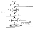
- FIG. 29 is a flowchart for explaining the detailed operation of step S3 shown in FIG. Referring to FIG. 29, after step S2 shown in FIG. 26, the image dividing circuit 3 receives the connection weight between the pixels in a plurality of pixels constituting one frame from the connection weight determination circuit 2, and the method described above. To determine the leader cell (step S41).
- step S42 determines whether or not a self-ignitable cell has been detected.
- self-ignition is performed by the method described above (step S42). S43).
- the image dividing circuit 3 determines whether or not the ignition cell exists (step S44). When the ignition cell exists, the image division circuit 3 performs ignition (region growth) to the surroundings by the above-described method (step S45). And a series of operation
- step S44 If it is determined in step S44 that no ignition cell is present, the image dividing circuit 3 performs the end of ignition and determination of the area and labels (fire suppression) by the above-described method (step S46). Thereafter, the series of operations returns to step S42, and steps S42 to S46 are repeatedly executed until it is determined in step S42 that no self-ignitable cell is detected.
- step S42 If it is determined in step S42 that no self-ignitable cell is detected, the series of operations proceeds to “END” in FIG.
- the image dividing device 10 repeatedly executes the flowchart shown in FIG. 26 (FIGS. 27 to 29), and divides each frame into images of the respective objects.
- the connection weight between the two pixels is determined only by the RGB values of the two pixels. (See Step S272) When only one of the two saturations is equal to or less than the threshold value Sth, the connection weight between the two pixels is determined based on the RGB values and saturations of the two pixels (see Step S274). When both of the two chromas of one pixel are larger than the threshold value Sth, the combination weight is determined by the two RGB values and the hue (see step S275).
- connection weight determined in step S274 is smaller than the connection weight determined in step S272, and the connection weight determined in step S275 is equal to or greater than the connection weight determined in step S272.
- the connection weight between the two pixels is determined using the saturation or the hue.
- connection weight is determined to be smaller than the connection weight determined only by the RGB values (see step S274), so that the region growth is suppressed in the image division.
- the combination weight is determined to be equal to or greater than the combination weight determined only by the RGB values (see step S275), so that region growth is promoted in the image division.
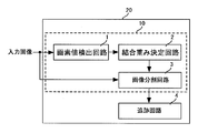
- FIG. 30 is a block diagram of an object tracking device using the image dividing device 10 according to the present invention.
- the object tracking device 20 is obtained by adding a tracking circuit 4 to the image dividing device 10.
- the tracking circuit 4 sequentially receives the divided images DVG1 and DVG2 from the image dividing circuit 3, and extracts the feature quantities CH1 and CH2 of the object represented by the received divided images DVG1 and DVG2. Then, the tracking circuit 4 performs object pattern matching between the divided images DVG1 and DVG2 using the extracted object feature amounts CH1 and CH2, detects a motion vector, and obtains an estimated position of the object.
- the object feature amounts CH1 and CH2 include, for example, the height, color, and area of the object. Pattern matching is performed by calculating a Manhattan distance or the like and obtaining a minimum Manhattan distance or the like.
- the tracking circuit 4 can accurately track an object using the accurately divided image.
- the conversion from RGB values to saturation (S) or hue (H) has been described using an adder and a shifter.
- the present invention is not limited to this, and the circuit area is not limited to this. If there is no special restriction such as no problem, the RGB value may be converted into saturation (S) or hue (H) by a circuit using a divider.
- the threshold value Sth is set to 0.2.
- the present invention is not limited to this, and the threshold value Sth may be a value other than 0.2. In general, it is generally determined experimentally based on the hue of each object of the input image to be image-divided.
- the image division is performed using the region growing type image division method.
- the image division is not limited to this, and “B. Jehehne,“ Digital Image Processing 5th ”. revised and extended edition, “Springer-Verlag, pp. 427-440, 2001.”, “J. C. Russ,“ The Image Processing Handbook, ”“ CRC PRESS, pp. 371-429, 1999.36 ”, “T. Braeunl, S. Feyrer, W. Rapf, and M. Reinhardt,“ Parallel Image Processing, ”Springer-Verlag, 2000.” and “W. Y. Ma, and B. S. Manjunath,“ Edgeflow: a technique for boundary detection and segmentation, IEEE Transactions on Image Processing, vol. 9 (8), pp. 1375-1388, 2004. ” Good.
- connection weight determined only by the RGB value constitutes the “first connection weight”, and the connection weight determined by the RGB value and the saturation (S) is the first connection weight.
- a “second combination weight” that is smaller than the first combination weight and that is determined by the RGB value and the hue (H) forms a “third combination weight” that is equal to or greater than the first combination weight.
- the pixel value difference 01xxx_xxxx shown in Table 3 constitutes a “first value”
- the pixel value difference 0001_xxxx constitutes a “second value” larger than the first value
- the present invention is applied to an image dividing apparatus capable of accurately dividing an input image composed of color images into images of respective objects.
- the present invention is applied to an image dividing method capable of accurately dividing an input image composed of color images into images of respective objects.
Landscapes
- Engineering & Computer Science (AREA)
- Computer Vision & Pattern Recognition (AREA)
- Physics & Mathematics (AREA)
- General Physics & Mathematics (AREA)
- Theoretical Computer Science (AREA)
- Color Image Communication Systems (AREA)
- Facsimile Image Signal Circuits (AREA)
- Image Processing (AREA)
- Image Analysis (AREA)
Abstract
Description












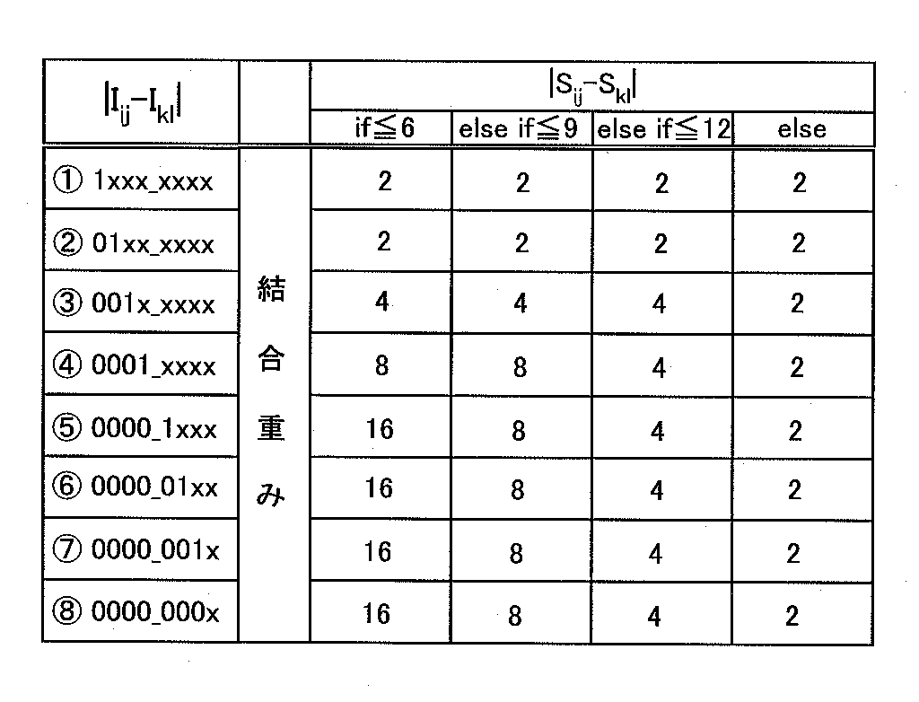
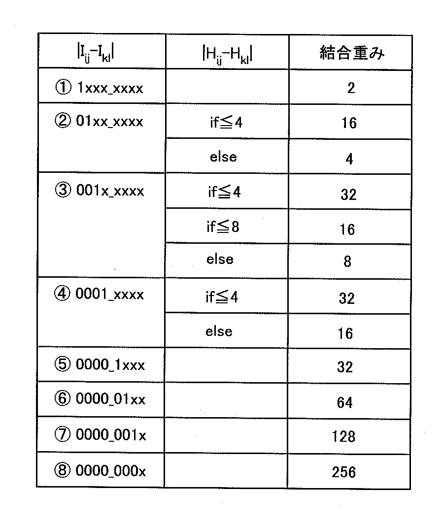
Claims (17)
- 2つの画素の両方が無彩色からなるとき、前記2つの画素のRGB値を用いて前記2つの画素間の結合重みである第1の結合重みを決定し、前記2つの画素の一方が無彩色からなるとき、前記第1の結合重みよりも小さい第2の結合重みを前記2つの画素間の結合重みとして決定し、前記2つの画素の両方が有彩色からなるとき、前記第1の結合重み以上の第3の結合重みを前記2つの画素間の結合重みとして決定する結合重み決定処理を1つのフレームの各画素間について実行する結合重み決定回路と、
前記結合重み決定回路によって決定された第1から第3の結合重みに基づいて、前記1つのフレームを各対象物の画像に分割する画像分割回路とを備える画像分割装置。 - 前記結合重み決定回路は、前記2つの画素のRGB値に基づいて前記2つの画素の第1および第2の彩度を演算するとともに、その演算した第1および第2の彩度を無彩色と有彩色との境界を示すしきい値と比較して前記2つの画素が前記無彩色および前記有彩色のいずれからなるかを判定し、その判定結果に基づいて前記第1から第3の結合重みのいずれかを前記2つの画素間の結合重みとして決定する、請求の範囲第1項に記載の画像分割装置。
- 前記結合重み決定回路は、加算器およびシフト器とを用いて前記2つの画素のRGB値に基づいて前記2つの画素の第1および第2の彩度を演算する、請求の範囲第2項に記載の画像分割装置。
- 前記結合重み決定回路は、前記演算した第1および第2の彩度の両方が前記しきい値以下であるとき、前記2つの画素の両方が前記無彩色からなると判定し、前記第1および第2の彩度の一方が前記しきい値以下であるとき、前記2つの画素の一方が前記無彩色からなり、かつ、前記2つの画素の他方が前記有彩色からなると判定し、前記第1および第2の彩度の両方が前記しきい値よりも大きいとき、前記2つの画素の両方が前記有彩色からなると判定する、請求の範囲第2項に記載の画像分割装置。
- 前記結合重み決定回路は、前記2つの画素の両方が前記無彩色からなると判定したとき、前記2つの画素のRGB値のみを用いて前記第1の結合重みを決定し、前記2つの画素の一方が前記無彩色からなり、かつ、前記2つの画素の他方が前記有彩色からなると判定したとき、前記2つの画素のRGB値および彩度を用いて前記第2の結合重みを決定し、前記2つの画素の両方が前記有彩色からなると判定したとき、前記2つの画素のRGB値および色相を用いて前記第3の結合重みを決定する、請求の範囲第3項に記載の画像分割装置。
- 前記結合重み決定回路は、前記RGB値のみを用いて前記第1の結合重みを演算するとともに、前記2つの画素の一方が前記無彩色からなり、かつ、前記2つの画素の他方が前記有彩色からなると判定したとき、前記演算した第1の結合重みを前記2つの画素の彩度の差である彩度差に応じて小さくすることにより前記第2の結合重みを決定し、前記2つの画素の両方が前記有彩色からなると判定したとき、前記2つの画素の色相の差である色相差に応じて前記第1の結合重みを大きくすることにより前記第3の結合重みを決定する、請求の範囲第5項に記載の画像分割装置。
- 前記結合重み決定回路は、前記2つの画素の両方が前記有彩色からなると判定したとき、前記2つの画素のRGB値に基づいて前記2つの画素の第1および第2の色相を演算するとともに、その演算した第1および第2の色相の差を前記色相差として演算し、その演算した色相差を用いて前記第3の結合重みを決定する、請求の範囲第6項に記載の画像分割装置。
- 前記結合重み決定回路は、加算器およびシフト器とを用いて前記2つの画素のRGB値に基づいて前記2つの画素の第1および第2の色相を演算する、請求の範囲第7項に記載の画像分割装置。
- 前記結合重み決定回路は、前記2つの画素の一方が前記無彩色からなり、かつ、前記2つの画素の他方が前記有彩色からなると判定した場合において、前記彩度差が相対的に小さいとき、前記第1の結合重みからの下げ幅を相対的に小さくして前記第2の結合重みを決定し、前記彩度差が相対的に大きいとき、前記第1の結合重みからの下げ幅を相対的に大きくして前記第3の結合重みを決定する、請求の範囲第6項に記載の画像分割装置。
- 前記結合重み決定回路は、前記2つの画素のRGB値の差と、前記彩度差と、前記第1の結合重みから前記彩度差に応じて小さくした修正結合重みとの対応表を保持しており、前記2つの画素の前記彩度差を演算すると、その演算した彩度差に対応する修正結合重みを前記対応表から抽出し、その抽出した修正結合重みを前記第2の結合重みとして決定する、請求の範囲第9項に記載の画像分割装置。
- 前記結合重み決定回路は、前記2つの画素の両方が前記有彩色からなると判定した場合において、前記2つの画素のRGB値の差が光の反射の影響を受けていることを示すとき、前記色相差に応じて前記第1の結合重み以上の値を設定して前記第3の結合重みを決定する、請求の範囲第6項に記載の画像分割装置。
- 前記結合重み決定回路は、前記2つの画素のRGB値の差が光の反射の影響を受けていないことを示すとき、前記第1の結合重みを前記第3の結合重みとして決定する、請求の範囲第11項に記載の画像分割装置。
- 前記結合重み決定回路は、前記2つの画素のRGB値の差と、前記色相差と、前記第1の結合重みから前記色相差に応じて大きくした修正結合重みとの対応表を保持しており、前記2つの画素のRGB値の差が光の反射の影響を受けていることを示すとき、前記2つの画素の前記色相差を演算すると、その演算した色相差に対応する修正結合重みを前記対応表から抽出し、その抽出した修正結合重みを前記第3の結合重みとして決定する、請求の範囲第11項に記載の画像分割装置。
- 2つの画素のRGB値を受付ける第1のステップと、
前記受付けられた2つの画素のRGB値に基づいて、前記2つの画素の第1および第2の色相を演算する第2のステップと、
前記受付けられた2つの画素のRGB値に基づいて、前記2つの画素の第1および第2の彩度を演算する第3のステップと、
前記第1および第2の彩度の両方が無彩色と無彩色との境界を示すしきい値以下であるか否かを判定する第4のステップと、
前記第4のステップにおいて、前記第1および第2の彩度の両方が前記しきい値以下であると判定されたとき、前記2つの画素のRGB値のみを用いて前記2つの画素間の結合重みである第1の結合重みを決定する第5のステップと、
前記第4のステップにおいて、前記第1および第2の彩度の一方が前記しきい値以下であると判定されたとき、前記2つの画素のRGB値と、前記第1および第2の彩度とを用いて前記第1の結合重みよりも小さい第2の結合重みを前記2つの画素間の結合重みとして決定する第6のステップと、
前記第4のステップにおいて、前記第1および第2の彩度の両方が前記しきい値よりも大きいと判定されたとき、前記2つの画素のRGB値と、前記第1および第2の色相とを用いて前記第1の結合重み以上の第3の結合重みを前記2つの画素間の結合重みとして決定する第7のステップと、
前記第1のステップから前記第7のステップを1つのフレームに含まれる全ての画素間について実行する第8のステップと、
前記第8のステップを実行して決定された第1から第3の結合重みに基づいて、前記1つのフレームを各対象物の画像に分割する第9のステップとを備える画像分割方法。 - 前記第6のステップは、
前記RGB値のみを用いて前記第1の結合重みを演算する第1のサブステップと、
前記演算した第1の結合重みを前記2つの画素の彩度の差である彩度差に応じて小さくすることにより前記第2の結合重みを決定する第2のサブステップとを含み、
前記第7のステップは、
前記RGB値のみを用いて第1の結合重みを演算する第3のサブステップと、
前記2つの画素が光の反射の影響を受けていることを示すとき、前記演算した第1の結合重みを前記2つの画素の色相の差である色相差に応じて大きくすることにより前記第3の結合重みを決定する第4のサブステップと、
前記2つの画素が光の反射の影響を受けていないことを示すとき、前記演算された第1の結合重みを前記第3の結合重みとして決定する第5のサブステップとを含む、請求の範囲第14項に記載の画像分割方法。 - 前記第2のサブステップにおいて、前記彩度差が相対的に小さいとき、前記第1の結合重みからの下げ幅を相対的に小さくして前記第2の結合重みを決定し、前記彩度差が相対的に大きいとき、前記第1の結合重みからの下げ幅を相対的に大きくして前記第2の結合重みを決定する、請求の範囲第15項に記載の画像分割方法。
- 前記光の反射の影響を受けている画素は、前記2つの画素のRGB値の差が第1の値と前記第1の値よりも大きい第2の値との間で存在する画素である、請求の範囲第15項に記載の画像分割方法。
Priority Applications (3)
| Application Number | Priority Date | Filing Date | Title |
|---|---|---|---|
| US12/601,595 US7853075B2 (en) | 2008-07-31 | 2008-07-31 | Image segmentation apparatus and image segmentation method |
| PCT/JP2008/002066 WO2010013291A1 (ja) | 2008-07-31 | 2008-07-31 | 画像分割装置および画像分割方法 |
| JP2008542958A JP4229980B1 (ja) | 2008-07-31 | 2008-07-31 | 画像分割装置および画像分割方法 |
Applications Claiming Priority (1)
| Application Number | Priority Date | Filing Date | Title |
|---|---|---|---|
| PCT/JP2008/002066 WO2010013291A1 (ja) | 2008-07-31 | 2008-07-31 | 画像分割装置および画像分割方法 |
Publications (1)
| Publication Number | Publication Date |
|---|---|
| WO2010013291A1 true WO2010013291A1 (ja) | 2010-02-04 |
Family
ID=40445133
Family Applications (1)
| Application Number | Title | Priority Date | Filing Date |
|---|---|---|---|
| PCT/JP2008/002066 Ceased WO2010013291A1 (ja) | 2008-07-31 | 2008-07-31 | 画像分割装置および画像分割方法 |
Country Status (3)
| Country | Link |
|---|---|
| US (1) | US7853075B2 (ja) |
| JP (1) | JP4229980B1 (ja) |
| WO (1) | WO2010013291A1 (ja) |
Cited By (1)
| Publication number | Priority date | Publication date | Assignee | Title |
|---|---|---|---|---|
| JP2010123114A (ja) * | 2008-10-24 | 2010-06-03 | Hiroshima Univ | 画像分割装置および画像分割方法 |
Families Citing this family (13)
| Publication number | Priority date | Publication date | Assignee | Title |
|---|---|---|---|---|
| JP2009239418A (ja) * | 2008-03-26 | 2009-10-15 | Seiko Epson Corp | 画像処理装置、画像処理方法、およびプログラム |
| US8131068B2 (en) * | 2008-06-06 | 2012-03-06 | Nikon Corporation | Image matching device and camera |
| US8150150B2 (en) * | 2009-03-02 | 2012-04-03 | Himax Technologies Limited | Method and system of extracting a perceptual feature set |
| US8625889B2 (en) * | 2010-12-30 | 2014-01-07 | Samsung Electronics Co., Ltd. | System for food recognition method using portable devices having digital cameras |
| JP5671349B2 (ja) * | 2011-01-06 | 2015-02-18 | 任天堂株式会社 | 画像処理プログラム、画像処理装置、画像処理システム、および画像処理方法 |
| KR101767269B1 (ko) * | 2011-04-25 | 2017-08-10 | 한국전자통신연구원 | 영상 검색 장치 및 방법 |
| JP5000781B1 (ja) * | 2011-11-09 | 2012-08-15 | 楽天株式会社 | 画像処理装置、画像処理装置の制御方法、プログラム、及び情報記憶媒体 |
| TWI510101B (zh) * | 2013-09-12 | 2015-11-21 | Au Optronics Corp | 飽和度調整方法與色彩調整系統 |
| DE102014106224A1 (de) * | 2014-05-05 | 2015-11-05 | Carl Zeiss Microscopy Gmbh | Verfahren zum Segmentieren eines Farbbildes sowie digitales Mikroskop |
| US11608417B2 (en) * | 2017-06-30 | 2023-03-21 | Nutrition & Biosciences USA 4, Inc. | Polysaccharide-elastomer masterbatch compositions |
| CN116113984A (zh) * | 2020-09-17 | 2023-05-12 | 国立大学法人广岛大学 | 皮肤表面分析装置及皮肤表面分析方法 |
| CN116309639A (zh) * | 2023-03-16 | 2023-06-23 | 北京赛迈特锐医疗科技有限公司 | 从彩色分类热图中分割关注区域的方法、装置及存储介质 |
| CN121062182B (zh) * | 2025-11-10 | 2026-02-06 | 德阳洋诚塑业有限公司 | 一种挤塑拉丝色差检测方法及系统 |
Citations (2)
| Publication number | Priority date | Publication date | Assignee | Title |
|---|---|---|---|---|
| JPH1196364A (ja) * | 1997-09-17 | 1999-04-09 | Minolta Co Ltd | 画像特徴量比較装置および画像特徴量比較プログラムを記録した記録媒体 |
| JP2003346142A (ja) * | 2002-05-27 | 2003-12-05 | Univ Hiroshima | 画像分割処理方法、画像分割処理装置、リアルタイム画像処理方法、リアルタイム画像処理装置及び画像処理集積化回路 |
Family Cites Families (4)
| Publication number | Priority date | Publication date | Assignee | Title |
|---|---|---|---|---|
| JPH06259549A (ja) | 1993-03-08 | 1994-09-16 | Nippon Telegr & Teleph Corp <Ntt> | 画像領域分割装置 |
| JP4071701B2 (ja) * | 2003-11-11 | 2008-04-02 | 富士通株式会社 | カラー画像の圧縮方法及びカラー画像圧縮装置 |
| KR20070008601A (ko) * | 2004-03-24 | 2007-01-17 | 세르늄 코포레이션 | 영역에 의한 세그먼트화 이득을 이용한 비디오 분석의 개선 |
| US7653242B2 (en) * | 2005-11-15 | 2010-01-26 | Honeywell International Inc. | Dynamically adjusting and predicting image segmentation threshold |
-
2008
- 2008-07-31 US US12/601,595 patent/US7853075B2/en not_active Expired - Fee Related
- 2008-07-31 WO PCT/JP2008/002066 patent/WO2010013291A1/ja not_active Ceased
- 2008-07-31 JP JP2008542958A patent/JP4229980B1/ja not_active Expired - Fee Related
Patent Citations (2)
| Publication number | Priority date | Publication date | Assignee | Title |
|---|---|---|---|---|
| JPH1196364A (ja) * | 1997-09-17 | 1999-04-09 | Minolta Co Ltd | 画像特徴量比較装置および画像特徴量比較プログラムを記録した記録媒体 |
| JP2003346142A (ja) * | 2002-05-27 | 2003-12-05 | Univ Hiroshima | 画像分割処理方法、画像分割処理装置、リアルタイム画像処理方法、リアルタイム画像処理装置及び画像処理集積化回路 |
Cited By (1)
| Publication number | Priority date | Publication date | Assignee | Title |
|---|---|---|---|---|
| JP2010123114A (ja) * | 2008-10-24 | 2010-06-03 | Hiroshima Univ | 画像分割装置および画像分割方法 |
Also Published As
| Publication number | Publication date |
|---|---|
| JPWO2010013291A1 (ja) | 2012-01-05 |
| US20100202684A1 (en) | 2010-08-12 |
| JP4229980B1 (ja) | 2009-02-25 |
| US7853075B2 (en) | 2010-12-14 |
Similar Documents
| Publication | Publication Date | Title |
|---|---|---|
| JP4229980B1 (ja) | 画像分割装置および画像分割方法 | |
| JP4870363B2 (ja) | 複数のフォアグランド平面を有する高圧縮画像データファイルの生成装置、方法及びプログラムを記憶した記憶媒体 | |
| JP5103665B2 (ja) | 物体追跡装置および物体追跡方法 | |
| Ganesan et al. | Segmentation and edge detection of color images using CIELAB color space and edge detectors | |
| JP5647878B2 (ja) | 鋼管内部腐食解析装置及び鋼管内部腐食解析方法 | |
| US8768017B2 (en) | Image processing apparatus, computer readable recording medium storing therein image processing program, and image processing method | |
| Su et al. | Combination of document image binarization techniques | |
| US9773185B2 (en) | Image processing apparatus, image processing method, and computer readable recording device | |
| CN107657619B (zh) | 一种低照度林火图像分割方法 | |
| WO2013080868A1 (ja) | 画像処理装置、画像処理方法、及び画像処理プログラム | |
| EP4113433A1 (en) | Classification and improvement of quality of vascular images | |
| CN108830874A (zh) | 一种数字病理全切片图像空白区域自动分割方法 | |
| WO2022267270A1 (zh) | 基于多重分形谱的裂纹特征表征方法及系统 | |
| JP5223133B2 (ja) | 画像分割装置および画像分割方法 | |
| CN117474846A (zh) | 基于改进lbp算法的光伏电池板缺陷检测方法和装置 | |
| CN117710287A (zh) | 物料检测方法、装置、电子设备及存储介质 | |
| CN112365485A (zh) | 一种基于Circular LBP和颜色空间转换算法的黑色素瘤识别方法 | |
| CN121095127A (zh) | 荧光显微图像智能增强方法、装置及可读存储介质 | |
| JP2009027715A (ja) | 画像データの色補正方法及びシステム | |
| KR20120042988A (ko) | 화상 처리 방법, 화상 처리 장치 및 프로그램 | |
| Abraham et al. | Low lightness image enhancement using modified DCP based lightness mapping in lab color space | |
| Chen | A pcb image self-adaption threshold segmentation method fusing color information and otsu theory | |
| Shu et al. | Image enhancement revisited: From first order to second order statistics | |
| Ismail et al. | A simple approach to determine the best threshold value for automatic image thresholding | |
| CN108447066A (zh) | 胆道图像分割方法、终端、存储介质 |
Legal Events
| Date | Code | Title | Description |
|---|---|---|---|
| ENP | Entry into the national phase |
Ref document number: 2008542958 Country of ref document: JP Kind code of ref document: A |
|
| WWE | Wipo information: entry into national phase |
Ref document number: 12601595 Country of ref document: US |
|
| 121 | Ep: the epo has been informed by wipo that ep was designated in this application |
Ref document number: 08790330 Country of ref document: EP Kind code of ref document: A1 |
|
| NENP | Non-entry into the national phase |
Ref country code: DE |
|
| 122 | Ep: pct application non-entry in european phase |
Ref document number: 08790330 Country of ref document: EP Kind code of ref document: A1 |