WO2009154174A1 - Electronic endoscope - Google Patents
Electronic endoscope Download PDFInfo
- Publication number
- WO2009154174A1 WO2009154174A1 PCT/JP2009/060885 JP2009060885W WO2009154174A1 WO 2009154174 A1 WO2009154174 A1 WO 2009154174A1 JP 2009060885 W JP2009060885 W JP 2009060885W WO 2009154174 A1 WO2009154174 A1 WO 2009154174A1
- Authority
- WO
- WIPO (PCT)
- Prior art keywords
- electronic endoscope
- lens
- lens holder
- main body
- imaging
- Prior art date
Links
Images


Classifications
-
- H—ELECTRICITY
- H04—ELECTRIC COMMUNICATION TECHNIQUE
- H04N—PICTORIAL COMMUNICATION, e.g. TELEVISION
- H04N7/00—Television systems
- H04N7/18—Closed-circuit television [CCTV] systems, i.e. systems in which the video signal is not broadcast
-
- A—HUMAN NECESSITIES
- A61—MEDICAL OR VETERINARY SCIENCE; HYGIENE
- A61B—DIAGNOSIS; SURGERY; IDENTIFICATION
- A61B1/00—Instruments for performing medical examinations of the interior of cavities or tubes of the body by visual or photographical inspection, e.g. endoscopes; Illuminating arrangements therefor
- A61B1/00064—Constructional details of the endoscope body
- A61B1/00071—Insertion part of the endoscope body
- A61B1/0008—Insertion part of the endoscope body characterised by distal tip features
- A61B1/00096—Optical elements
-
- A—HUMAN NECESSITIES
- A61—MEDICAL OR VETERINARY SCIENCE; HYGIENE
- A61B—DIAGNOSIS; SURGERY; IDENTIFICATION
- A61B1/00—Instruments for performing medical examinations of the interior of cavities or tubes of the body by visual or photographical inspection, e.g. endoscopes; Illuminating arrangements therefor
- A61B1/00163—Optical arrangements
- A61B1/00172—Optical arrangements with means for scanning
-
- A—HUMAN NECESSITIES
- A61—MEDICAL OR VETERINARY SCIENCE; HYGIENE
- A61B—DIAGNOSIS; SURGERY; IDENTIFICATION
- A61B1/00—Instruments for performing medical examinations of the interior of cavities or tubes of the body by visual or photographical inspection, e.g. endoscopes; Illuminating arrangements therefor
- A61B1/00163—Optical arrangements
- A61B1/00174—Optical arrangements characterised by the viewing angles
- A61B1/00177—Optical arrangements characterised by the viewing angles for 90 degrees side-viewing
-
- A—HUMAN NECESSITIES
- A61—MEDICAL OR VETERINARY SCIENCE; HYGIENE
- A61B—DIAGNOSIS; SURGERY; IDENTIFICATION
- A61B1/00—Instruments for performing medical examinations of the interior of cavities or tubes of the body by visual or photographical inspection, e.g. endoscopes; Illuminating arrangements therefor
- A61B1/00163—Optical arrangements
- A61B1/00174—Optical arrangements characterised by the viewing angles
- A61B1/00183—Optical arrangements characterised by the viewing angles for variable viewing angles
-
- A—HUMAN NECESSITIES
- A61—MEDICAL OR VETERINARY SCIENCE; HYGIENE
- A61B—DIAGNOSIS; SURGERY; IDENTIFICATION
- A61B1/00—Instruments for performing medical examinations of the interior of cavities or tubes of the body by visual or photographical inspection, e.g. endoscopes; Illuminating arrangements therefor
- A61B1/04—Instruments for performing medical examinations of the interior of cavities or tubes of the body by visual or photographical inspection, e.g. endoscopes; Illuminating arrangements therefor combined with photographic or television appliances
- A61B1/042—Instruments for performing medical examinations of the interior of cavities or tubes of the body by visual or photographical inspection, e.g. endoscopes; Illuminating arrangements therefor combined with photographic or television appliances characterised by a proximal camera, e.g. a CCD camera
-
- A—HUMAN NECESSITIES
- A61—MEDICAL OR VETERINARY SCIENCE; HYGIENE
- A61B—DIAGNOSIS; SURGERY; IDENTIFICATION
- A61B1/00—Instruments for performing medical examinations of the interior of cavities or tubes of the body by visual or photographical inspection, e.g. endoscopes; Illuminating arrangements therefor
- A61B1/04—Instruments for performing medical examinations of the interior of cavities or tubes of the body by visual or photographical inspection, e.g. endoscopes; Illuminating arrangements therefor combined with photographic or television appliances
- A61B1/045—Control thereof
-
- A—HUMAN NECESSITIES
- A61—MEDICAL OR VETERINARY SCIENCE; HYGIENE
- A61B—DIAGNOSIS; SURGERY; IDENTIFICATION
- A61B1/00—Instruments for performing medical examinations of the interior of cavities or tubes of the body by visual or photographical inspection, e.g. endoscopes; Illuminating arrangements therefor
- A61B1/04—Instruments for performing medical examinations of the interior of cavities or tubes of the body by visual or photographical inspection, e.g. endoscopes; Illuminating arrangements therefor combined with photographic or television appliances
- A61B1/05—Instruments for performing medical examinations of the interior of cavities or tubes of the body by visual or photographical inspection, e.g. endoscopes; Illuminating arrangements therefor combined with photographic or television appliances characterised by the image sensor, e.g. camera, being in the distal end portion
Definitions
- FIG. 6A It is a perspective view explaining the drive part which moves the lens holder holding an objective lens in the endoscope of FIG. It is a perspective view which fractures
- an imaging process is performed (step S2).
- the LED 55 is driven to irradiate illumination light
- the subject light is taken into the endoscope 1 from the objective lens 17 to form an image on the light receiving surface of the imaging element 23, and read out from the imaging element 23.
- Subject light is collected by the objective lens 17 through the cylindrical portion 313c of the translucent cover 313 and travels toward the objective mirror 16 as a parallel light flux. Then, the subject light is reflected by the reflecting surface of the objective mirror 16 and travels on the central axis of the cylindrical portion 315, in other words, on the central axis of the outer shell as a parallel light flux.
- the stepping motor 61 is driven with the designated number of pulses in step S3, the lens holder 319 is lowered and rotated, and the next field of view is “No. 002 ". Then, imaging is performed in the field of view of “No. 002”, and image data of the field of view of “No. 002” is generated from the imaging signal read from the image sensor 23.
- An illumination lens 557 that deflects the illumination light so as to be a parallel light beam with respect to the half mirror 553 is provided between the LED 555 and the half mirror 553.
- the half mirror 553, the illumination lens 557, and the LED 555 are fixed in the main body 511 by appropriate support members.
- the endoscope 500 can be configured to send captured image data to an external monitor so that the captured image can be observed on-line on the external monitor and to input an operation instruction from the outside.
- the control unit 581 sends the image signal acquired from the image sensor 523 to the external video processor as it is without performing image processing, and displays the subject image image-processed by the video processor on the external monitor.
- Communication between the external video processor or external monitor and the control unit 581 may be wired or wireless. When performing wired communication, an external power source can be used by inserting a power line in the wiring.
- the lens holder in the translucent cover is moved forward and backward by the drive unit, so that images can be taken from different positions on the central axis of the cylindrical portion of the lens holder and taken in from the wide-angle lens.
- the acquired image information can be accurately acquired within the moving range of the lens holder. Thereby, it is possible to easily acquire a wide range of continuous images without moving the electronic endoscope within the subject.
- the stepping motor 628 having the specified number of pulses is driven in step S5, and thus the cylindrical member 604b rotates by the specified number of pulses.
- the cylindrical member 604b is screwed into the main body 602 and retracted, and the next field of view is “No. 002” in FIG. 53.
- a subject image in this field of view is captured, and the image data is imaged. It is stored in the memory 626.
- the moving lens frame portion 604 is rotationally driven by the stepping motor 628.
- a motor that can accurately control the rotation angle and the rotation length is acceptable even if it is not a stepping motor. Needless to say.
- the outer shell is formed in a cylindrical shape
- a thread groove is formed on the inner peripheral surface of the peripheral wall
- the drive mechanism includes a lens holder that supports the objective lens, and the outer A motor for rotating the lens holder about the axis of the shell as a rotation axis, wherein the lens holder is engaged with the screw groove of the outer shell.
- the present specification discloses an electronic endoscope characterized in that an image memory for receiving and storing the image data transmitted wirelessly is provided in the main body.
- a stepping motor 1291 is installed on the uppermost substrate (on the opposite side to the bottom 1211a side) 1243.
- a motor gear (spur gear) 1293 is attached to the rotating shaft of the stepping motor 1291.
- control unit that performs image processing on an image signal obtained by the imaging unit and an image memory that stores image data processed by the control unit are incorporated in the main body unit.
- An electronic endoscope characterized by this is disclosed.
Abstract
Provided is an electronic endoscope having a novel structure wherein image information of a large area in detail can be simply and accurately obtained.
An electronic endoscope (1) is provided with an outer envelope, which is cylindrically formed and has a transparent cylindrical section (13c) extending in the axis direction on the circumferential wall; a solid-sate imaging element (23) arranged inside the outer envelop; an objective optical system, which includes an objective lens (17) which collects object light through a window section and forms an image on the solid-state imaging element; and a driving mechanism for moving at least the objective lens of the objective optical system along the axis of the outer envelop.
Description
本発明は電子内視鏡に関する。
The present invention relates to an electronic endoscope.
特許文献1に記載の電子内視鏡は、孔内あるいは体腔内に細い挿入部を挿入し、挿入部の先端に取り付けた対物レンズを挿入方向の患部等に向け、画像情報を取得するようにしている。
In the electronic endoscope described in Patent Document 1, a thin insertion portion is inserted into a hole or body cavity, and an objective lens attached to the distal end of the insertion portion is directed toward an affected portion in the insertion direction to acquire image information. ing.
また、特許文献2に記載の電子内視鏡は、挿入部の先端部の側面に対物レンズを設け、側方に広がる視野内の画像を撮像するようにしている。
In addition, the electronic endoscope described in Patent Document 2 is provided with an objective lens on the side surface of the distal end portion of the insertion portion so as to capture an image in the field of view spreading laterally.
また、特許文献3に記載の電子内視鏡は、挿入部の先端に全方位受光ユニットを設け、挿入部の先端の周方向全周にわたる画像を全方位受光ユニット内の凸面鏡に反射させて、撮像するようにしている。
In addition, the electronic endoscope described in Patent Document 3 is provided with an omnidirectional light receiving unit at the tip of the insertion portion, and reflects an image over the entire circumference in the circumferential direction of the tip of the insertion portion to the convex mirror in the omnidirectional light reception unit, I try to take an image.
また、特許文献4に記載の電子内視鏡は、医療分野で消化管の検診に用いられるカプセル型の電子内視鏡であって、撮像装置を内蔵し、消化管の蠕動運動によって消化管の内部を搬送されながら消化管の内部を撮像してゆく。
In addition, the electronic endoscope described in Patent Document 4 is a capsule-type electronic endoscope used for examination of the digestive tract in the medical field, and includes an imaging device. The inside of the digestive tract is imaged while being transported inside.
電子内視鏡の先端部に収納される撮像素子は、デジタルカメラ等に用いられる固体撮像素子より小面積、少画素数のものが多い。従って、患部等の詳細画像を撮像しようとした場合、1回1回の撮像で得られる画像情報は、夫々狭い視野範囲の画像に限られる。
The image pickup device housed in the tip of the electronic endoscope has a smaller area and a smaller number of pixels than a solid-state image pickup device used for a digital camera or the like. Therefore, when trying to capture a detailed image of an affected area or the like, image information obtained by one imaging is limited to an image with a narrow visual field range.
このため、広い範囲の画像情報を綿密に取得しようとすると、内視鏡の操作者は、内視鏡の挿入位置を手操作で調整しながら複数回にわたり撮像することになる。つまり、患部等の探索すなわち挿入位置の調整作業と、撮像作業との両方に注意を払わなければならず、この作業には熟練を要していた。
For this reason, if an attempt is made to acquire a wide range of image information closely, the operator of the endoscope takes images a plurality of times while manually adjusting the insertion position of the endoscope. That is, attention must be paid to both the search for the affected area, that is, the adjustment of the insertion position and the imaging work, and this work requires skill.
また、挿入部先端全周の画像を全方位受光ユニットを用いて撮像する内視鏡の場合には、撮像した挿入位置全周範囲の画像情報を一度に得ることができるが、撮像部位は挿入位置の幅の狭い領域に限られる。そのため、広範囲な全周画像情報を得るためには、挿入位置を逐一調整しながら撮像することになり、画像同士のつなぎ目の情報が欠落したり、無駄な撮像を繰り返したりすることになりかねない。
In addition, in the case of an endoscope that captures an image of the entire circumference of the distal end of the insertion section using an omnidirectional light receiving unit, it is possible to obtain image information of the entire circumference of the insertion position that has been imaged. Limited to regions with narrow positions. Therefore, in order to obtain a wide range of omnidirectional image information, images are taken while adjusting the insertion positions one by one, which may result in missing information on joints between images or repeated useless imaging. .
また、カプセル型の内視鏡は、消化管の蠕動運動により消化管の内部を搬送される。そのため、視野を移動するための操作を要しないが、蠕動運動がない孔内あるいは体腔内には用いることができない。
Also, the capsule endoscope is transported inside the digestive tract by the peristaltic movement of the digestive tract. Therefore, although an operation for moving the visual field is not required, it cannot be used in a hole or a body cavity where there is no peristaltic movement.
本発明の目的は、広い範囲の詳細な画像情報を簡単に精度良く取得することが可能な新規な構造の電子内視鏡を提供することにある。
An object of the present invention is to provide an electronic endoscope having a novel structure capable of easily and accurately acquiring a wide range of detailed image information.
(1)筒状に形成され、その周壁に軸方向に延びる透明な窓部が設けられた外殻と、前記外殻の内部に設けられた固体撮像素子と、前記窓部を通して被写体光を集光する対物レンズを含み、前記固体撮像素子に結像する対物光学系と、前記対物光学系の少なくとも前記対物レンズを前記外殻の軸に沿って移動させる駆動機構と、を備えることを特徴とする電子内視鏡。
(2)被検体の内部に挿入して被検体内を撮像する電子内視鏡であって、筒状部を有するレンズホルダと、前記レンズホルダに装着され、前記筒状部の一端側に、該筒状部の中心軸に光軸を合わせて配置し、前記筒状部の側方まで観察視野が広がる広角レンズと、前記広角レンズから取り込まれる光を受光し電気信号に変換する撮像素子と、前記筒状部の一端側を覆い、少なくとも前記広角レンズの観察視野内に対面する部位が透光性を有する透光性カバーと、前記筒状部の他端側で前記透光性カバーと接続される筒状の本体部と、前記本体部内に配置され前記レンズホルダを前記中心軸方向に進退させる駆動部と、を備えることを特徴とする電子内視鏡。
(3)少なくとも円筒部の観察窓が透明である円筒状の透光性カバーと、前記透光性カバーの前記円筒部に連設される円筒部を有する本体部と、前記透光性カバー及び前記本体部の内部で該透光性カバーの中心軸を中心に回転すると共に該中心軸の方向に移動するレンズホルダと、前記レンズホルダに設けられ前記透光性カバーの前記円筒部に対面する位置に設けられた対物レンズを通して入射する光を前記本体部の方向に反射する対物ミラーと、前記対物ミラーで反射された光を受光し電気信号に変換する撮像素子と、前記本体部の内部に設けられ前記レンズホルダを回転駆動すると共に前記中心軸方向に駆動する駆動部と、を備えることを特徴とする電子内視鏡。 (1) An outer shell formed in a cylindrical shape and provided with a transparent window portion extending in the axial direction on a peripheral wall thereof, a solid-state image sensor provided inside the outer shell, and subject light is collected through the window portion. An objective optical system that forms an image on the solid-state imaging device, and a drive mechanism that moves at least the objective lens of the objective optical system along the axis of the outer shell. Electronic endoscope.
(2) An electronic endoscope that is inserted into a subject and images the inside of the subject, the lens holder having a cylindrical portion, and attached to the lens holder, on one end side of the cylindrical portion, A wide-angle lens in which the optical axis is aligned with the central axis of the cylindrical portion, and the observation field of view extends to the side of the cylindrical portion; and an imaging device that receives light taken from the wide-angle lens and converts it into an electrical signal; A translucent cover that covers one end side of the cylindrical part and at least a part facing the observation field of the wide-angle lens is translucent; and the translucent cover on the other end side of the cylindrical part; An electronic endoscope comprising: a cylindrical main body portion to be connected; and a driving portion that is disposed in the main body portion and moves the lens holder forward and backward in the central axis direction.
(3) A cylindrical translucent cover in which at least the observation window of the cylindrical portion is transparent, a main body having a cylindrical portion connected to the cylindrical portion of the translucent cover, the translucent cover, and A lens holder that rotates around the central axis of the translucent cover and moves in the direction of the central axis inside the main body, and faces the cylindrical part of the translucent cover that is provided on the lens holder. An objective mirror that reflects light incident through an objective lens provided at a position in the direction of the main body, an image sensor that receives the light reflected by the objective mirror and converts it into an electrical signal, and an inside of the main body An electronic endoscope comprising: a driving unit that is provided to rotate and drive the lens holder in the direction of the central axis.
本発明によれば、広い範囲の詳細な画像情報を簡単に精度良く取得することができる。
According to the present invention, detailed image information in a wide range can be acquired easily and accurately.
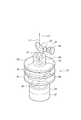
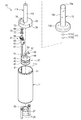
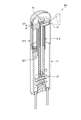
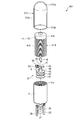
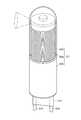
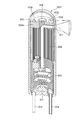
図1~図3に示す電子内視鏡1は、本体部11及び透光性カバー13で構成された外殻を備え、その内部に、透光性カバー13を通して被写体光を集光する対物レンズ17を保持したレンズホルダ19と、外殻内でレンズホルダ19を移動させる駆動部21と、対物レンズ17から取り込まれた被写体光を受光して電気信号に変換する固体撮像素子23と、を備えている。
An electronic endoscope 1 shown in FIGS. 1 to 3 includes an outer shell composed of a main body 11 and a translucent cover 13, and an objective lens that collects subject light through the translucent cover 13 therein. 17, a lens holder 19 that holds the lens holder 19, a drive unit 21 that moves the lens holder 19 within the outer shell, and a solid-state imaging device 23 that receives subject light captured from the objective lens 17 and converts it into an electrical signal. ing.
外殻の一部を構成する本体部11は、遮光性を有する樹脂材などで形成されており、一方の端部11aは閉じられ、他方の端部11cは開口した円筒形に成形されている。閉じられた端部(底部)11aには筒状の電池収納部11bが設けられている。この電池収納部11bは、電源電池25が装着された後に電池蓋27によって閉塞される。
The main body portion 11 constituting a part of the outer shell is formed of a light-shielding resin material or the like, one end portion 11a is closed, and the other end portion 11c is formed into an open cylindrical shape. . A cylindrical battery housing portion 11b is provided at the closed end (bottom portion) 11a. The battery housing portion 11b is closed by a battery lid 27 after the power supply battery 25 is mounted.
つまり、内視鏡1は、電源電池25を内蔵しており、外部からの電力供給を要しない。そのため、内視鏡1は、電力供給用のケーブルが接続される必要はなく、取り扱い性に優れる。
That is, the endoscope 1 has a built-in power supply battery 25 and does not require external power supply. Therefore, the endoscope 1 does not need to be connected with a power supply cable, and is excellent in handleability.
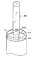
尚、図示の例では、底部11aに、2本の管29が外殻の外側に突出して設けられている。これらの管29は、例えば後述するメモリ83に格納された画像データや画像マップを外部の機器に転送する際に転送用のケーブルが挿通され、それを保護するために設けられている。また、管29は軟質なものであってもよいが、硬質なものとして、内視鏡1を使用する際に、内視鏡1を被検体の孔に挿入し、もしくは孔から引き出し、または内視鏡1を回転するための把持部としてもよい。
In the illustrated example, two pipes 29 are provided on the bottom 11a so as to protrude outside the outer shell. These tubes 29 are provided, for example, when a transfer cable is inserted and protected when transferring image data or an image map stored in a memory 83 to be described later to an external device. The tube 29 may be soft, but it is hard and when the endoscope 1 is used, the endoscope 1 is inserted into or pulled out of the hole of the subject, It is good also as a holding part for rotating the endoscope 1.
透光性カバー13は、円筒形に成形されており、一方の端部13bは開口している。透光性カバー13は、この開口端部13bを本体部11の開口端部11cに整合させ、接着等の適宜の手段により本体部11に固定されている。尚、内視鏡1において、外殻となる本体部11および透光性カバー13は、必ずしも円筒状である必要はなく、他の筒状であってもよい。
The translucent cover 13 is formed in a cylindrical shape, and one end 13b is open. The translucent cover 13 is fixed to the main body 11 by an appropriate means such as adhesion by aligning the open end 13b with the open end 11c of the main body 11. In the endoscope 1, the main body 11 and the translucent cover 13 that are outer shells are not necessarily cylindrical, and may be other cylindrical shapes.
透光性カバー13の他方の端部(先端部)13aは、被検体の孔内への挿入を容易にするために、滑らかな半球状に成形されている。そして、先端部13aと開口端部13bとは、先端部13aと同径に成形された円筒部13cにより接続されている。先端部13aおよび円筒部13cは、開口端部13bに比べて小径に成形されている。このように、半球状に成形された先端部13aおよび円筒部13cを細くすることで、比較的狭い被検体の孔内への挿入を容易とすることができ、内視鏡1の利用範囲を拡げることができる。
The other end portion (tip portion) 13a of the translucent cover 13 is formed into a smooth hemisphere in order to facilitate insertion of the subject into the hole. And the front-end | tip part 13a and the opening edge part 13b are connected by the cylindrical part 13c shape | molded by the same diameter as the front-end | tip part 13a. The tip portion 13a and the cylindrical portion 13c are formed with a smaller diameter than the opening end portion 13b. Thus, by narrowing the tip portion 13a and the cylindrical portion 13c formed in a hemispherical shape, it is possible to facilitate insertion of a relatively narrow subject into the hole, and the range of use of the endoscope 1 can be reduced. Can be expanded.
上記構成の透光性カバー13は、透明な樹脂材などを用い、例えば一体成形により作製することができる。また、半球状に成形される先端部13a、開口端部13b、および円筒部13cを個別の部材とし、接着等の適宜に手段により互いに接合して作製してもよい。その場合に、少なくとも、被検体の孔内の内周面を臨む窓部となる円筒部13cは透明に形成される。尚、本発明において透明とは、撮像素子23を感光させる特定の波長の光に対して透明であればよく、必ずしも可視光に対して透明でなくてもよい。
The translucent cover 13 having the above-described configuration can be manufactured by, for example, integral molding using a transparent resin material. Alternatively, the tip end portion 13a, the open end portion 13b, and the cylindrical portion 13c formed in a hemispherical shape may be formed as separate members and joined to each other by appropriate means such as adhesion. In that case, at least the cylindrical portion 13c serving as the window portion facing the inner peripheral surface in the hole of the subject is formed to be transparent. In the present invention, the term “transparent” may be transparent to light having a specific wavelength that sensitizes the image sensor 23, and may not necessarily be transparent to visible light.
レンズホルダ19は、樹脂材などで形成されており、本体部11に内嵌する円盤状の鍔部33と、鍔部33よりも小径に成形されて透光性カバー13の円筒部13c内に進入可能な筒状部15と、を有している。鍔部33は、その外径が本体部11の内径よりも若干小径に成形され、本体部11の中心軸、換言すれば外殻の中心軸に沿って本体部11内をガタツキなくスムースに移動できるようになっている。また、筒状部15は、その外径が透光性カバー13の円筒部13cの内径よりも若干小径に成形され、外殻の中心軸に沿って円筒部13c内でガタツキなくスムースに移動できるようになっている。
The lens holder 19 is formed of a resin material or the like. The lens holder 19 is fitted into the main body 11 and has a disk-shaped flange 33. The lens holder 19 is formed to have a smaller diameter than the flange 33 and is inserted into the cylindrical portion 13c of the translucent cover 13. And a cylindrical portion 15 that can enter. The flange 33 is formed to have an outer diameter slightly smaller than the inner diameter of the main body 11, and smoothly moves within the main body 11 along the central axis of the main body 11, in other words, along the central axis of the outer shell. It can be done. Further, the outer diameter of the cylindrical portion 15 is formed to be slightly smaller than the inner diameter of the cylindrical portion 13c of the translucent cover 13, and can be smoothly moved in the cylindrical portion 13c along the central axis of the outer shell. It is like that.
レンズホルダ19の鍔部33には、その外周面に係合溝35が形成されている。本体部11の内周面には、外殻の軸に沿って延びるリブ31が形成されており、レンズホルダ19は、鍔部33の係合溝35を本体部11のリブ31に係合させている。そのため、レンズホルダ19は、外殻の中心軸に沿って移動を案内され、後述する送りネジ67を回転軸とする回転を止められる。尚、図示の例では、2つの係合溝35が円周方向に間隔をおいて設けられているが、その数に特に制限はない。
An engagement groove 35 is formed on the outer peripheral surface of the collar portion 33 of the lens holder 19. A rib 31 extending along the axis of the outer shell is formed on the inner peripheral surface of the main body 11, and the lens holder 19 engages the engagement groove 35 of the flange 33 with the rib 31 of the main body 11. ing. Therefore, the lens holder 19 is guided to move along the central axis of the outer shell, and can stop rotating with a feed screw 67 (described later) as the rotation axis. In the illustrated example, the two engagement grooves 35 are provided at intervals in the circumferential direction, but the number thereof is not particularly limited.
筒状部15の先端部には、対物ミラー16が収納されている。この対物ミラー16は、円柱を、その中心軸に斜め45度で交差する傾斜面で切断した形状となっており、その傾斜面は反射膜が製膜されるなどして反射面とされている。
An objective mirror 16 is accommodated at the tip of the cylindrical portion 15. The objective mirror 16 has a shape obtained by cutting a cylinder by an inclined surface that intersects the central axis at an angle of 45 degrees, and the inclined surface is formed as a reflecting surface by, for example, forming a reflecting film. .
そして、筒状部15において対物ミラー16の反射面を径方向に臨む部位には撮像孔が形成されており、この撮像孔に対物レンズ17が設置されている。被写体光は、透光性カバー13の円筒部13cを通して対物レンズ17により集光され、平行光束として対物ミラー16に向けて進行する。そして、被写体光は、対物ミラー16の反射面で反射され、平行光束のまま、外殻の中心軸と平行に筒状部15の中心軸上を進行するようになっている。
An imaging hole is formed in a portion of the cylindrical portion 15 that faces the reflecting surface of the objective mirror 16 in the radial direction, and an objective lens 17 is installed in the imaging hole. The subject light is collected by the objective lens 17 through the cylindrical portion 13 c of the translucent cover 13 and travels toward the objective mirror 16 as a parallel light flux. The subject light is reflected by the reflecting surface of the objective mirror 16 and travels on the central axis of the cylindrical portion 15 in parallel with the central axis of the outer shell as a parallel light flux.
本体部11内において、レンズホルダ19の筒状部15の中心軸の延長線上にあたる位置には、撮像駆動ユニット部37が配置されている。撮像駆動ユニット部37は、図示しない固定部材を用いて本体部11内に固定されている。この撮像駆動ユニット部37は3枚の基板41,42,43を備えている。
In the main body 11, an imaging drive unit 37 is disposed at a position corresponding to an extension of the central axis of the cylindrical portion 15 of the lens holder 19. The imaging drive unit 37 is fixed in the main body 11 using a fixing member (not shown). The imaging drive unit unit 37 includes three substrates 41, 42, and 43.
図4に撮像駆動ユニット部37を拡大して示す。レンズホルダ19に最も接近して配置された基板43には、固体撮像素子23が設けられている。撮像素子23としては、CCD型イメージセンサやCMOS型イメージセンサなどを用いることができる。基板43の下(本体部11の底部11a側)に配置された基板42には、メモリ83が設けられている。このメモリ83は、撮像素子23から読み出された撮像信号から生成される画像データなどを格納する。そして、基板42の下に配置された基板41には、制御ユニット45が設けられている。この制御ユニット45は、例えば撮像素子23からの撮像信号の読み出し、読み出された撮像信号からの画像データの生成、等を行う。
FIG. 4 shows the image pickup drive unit 37 in an enlarged manner. A solid-state imaging device 23 is provided on the substrate 43 that is disposed closest to the lens holder 19. As the image sensor 23, a CCD image sensor, a CMOS image sensor, or the like can be used. A memory 83 is provided on the substrate 42 disposed below the substrate 43 (on the bottom 11a side of the main body 11). The memory 83 stores image data generated from an image pickup signal read from the image pickup device 23 and the like. A control unit 45 is provided on the substrate 41 disposed under the substrate 42. For example, the control unit 45 reads an image signal from the image sensor 23, generates image data from the read image signal, and the like.
撮像素子23は、基板43上でレンズホルダ19の筒状部15の中心軸の延長線上にあたる位置に設けられている。そして、筒状部15の中心軸の延長線上で撮像素子23の上方にあたる位置には集光レンズ51が配置されている。集光レンズ51は、撮像素子23を包囲するように基板43上に設置された集光レンズホルダ49に保持されている。この集光レンズ51は、筒状部15の中心軸上を平行光束として進行する被写体光L1を撮像素子23の受光面に結像させる。すなわち、対物レンズ17、対物ミラー16、および集光レンズ51により対物光学系が構成されている。
The image sensor 23 is provided on the substrate 43 at a position corresponding to an extension of the central axis of the cylindrical portion 15 of the lens holder 19. A condensing lens 51 is disposed at a position above the image sensor 23 on the extension line of the central axis of the cylindrical portion 15. The condenser lens 51 is held by a condenser lens holder 49 installed on the substrate 43 so as to surround the imaging device 23. The condensing lens 51 forms an image of the subject light L1 traveling as a parallel light beam on the central axis of the cylindrical portion 15 on the light receiving surface of the image sensor 23. That is, the objective lens 17, the objective mirror 16, and the condenser lens 51 constitute an objective optical system.
また、レンズホルダ19の筒状部15に収納された対物ミラー16と集光レンズ51との間の被写体光の光路上には、ハーフミラー53が配置されている。ハーフミラー53は、対物ミラー16から集光レンズ51に向けて進行する被写体光の少なくとも一部を透過させる。また、対物ミラー16と集光レンズ51との間の被写体光の光路から外れてハーフミラー53を臨む位置に、被写体を照明するための光源としての発光ダイオード(LED)55が設けられている。LED55から射出された照明光L2は、LED55とハーフミラー53との間に配置された照明レンズ57により平行光束とされてハーフミラー53に入射し、少なくともその一部が対物ミラー16に向けて反射される。そして、対物ミラー16に入射した照明光は、対物レンズ17に向けて反射され、対物レンズ17および透光性カバー13を通して被写体に照射される。尚、これらハーフミラー53、LED55、照明レンズ57は、それぞれ適宜な固定部材により本体部11内に固定されている。
Further, a half mirror 53 is disposed on the optical path of the subject light between the objective mirror 16 and the condenser lens 51 housed in the cylindrical portion 15 of the lens holder 19. The half mirror 53 transmits at least part of the subject light traveling from the objective mirror 16 toward the condenser lens 51. Further, a light emitting diode (LED) 55 as a light source for illuminating the subject is provided at a position facing the half mirror 53 outside the optical path of the subject light between the objective mirror 16 and the condenser lens 51. The illumination light L2 emitted from the LED 55 is converted into a parallel light flux by the illumination lens 57 disposed between the LED 55 and the half mirror 53 and is incident on the half mirror 53, and at least a part of the illumination light L2 is reflected toward the objective mirror 16. Is done. The illumination light incident on the objective mirror 16 is reflected toward the objective lens 17 and is irradiated onto the subject through the objective lens 17 and the translucent cover 13. The half mirror 53, the LED 55, and the illumination lens 57 are fixed in the main body 11 by appropriate fixing members.
ここで、レンズホルダ19は、上述のとおり鍔部33の係合溝35を本体部11のリブ31に係合させることにより、外殻の中心軸に沿って移動を案内されている。そして、外殻の中心軸に沿って移動を案内されたレンズホルダ19は、筒状部15に保持した対物レンズ17の高さが図5Aに示すh1から、図5Bに示す高さhnとなるまで移動可能となっている。以下に、レンズホルダ19を移動させる駆動部21について、図3、図6A、図6B、及び図7を参照しつつ詳細に説明する。
Here, the lens holder 19 is guided to move along the central axis of the outer shell by engaging the engaging groove 35 of the flange 33 with the rib 31 of the main body 11 as described above. In the lens holder 19 guided to move along the central axis of the outer shell, the height of the objective lens 17 held by the cylindrical portion 15 is changed from h1 shown in FIG. 5A to a height hn shown in FIG. 5B. It is possible to move to. Below, the drive part 21 which moves the lens holder 19 is demonstrated in detail, referring FIG. 3, FIG. 6A, FIG. 6B, and FIG.
本体部11内には、外殻の中心軸と平行に配置された送りネジ67と、送りネジ67を回転駆動する動力源としてのステッピングモータ61と、が設けられている。ステッピングモータ61の回転軸にはモータギア63が一体に取り付けられ、送りネジ67の一端部にはギア69が一体に取り付けられている。そして、モータギア63とギア69との間に介在して、両ギア63、69にそれぞれ噛み合うアイドルギア65が設けられている。ステッピングモータ61およびアイドルギア65は、適宜な固定部材により本体部11内に固定されている。また、送りネジ67は、図7に示すように、透光性カバー13の開口端部13bのフランジ面に形成された軸穴13dに一端部を挿入し、撮像駆動ユニット部37の集光レンズホルダ49の側方に設けた支持アーム71に他端部を支持され、その中心軸まわりに回転可能となっている。
In the main body 11, a feed screw 67 disposed in parallel with the central axis of the outer shell, and a stepping motor 61 as a power source that rotationally drives the feed screw 67 are provided. A motor gear 63 is integrally attached to the rotating shaft of the stepping motor 61, and a gear 69 is integrally attached to one end portion of the feed screw 67. An idle gear 65 is provided between the motor gear 63 and the gear 69 and meshes with the gears 63 and 69, respectively. The stepping motor 61 and the idle gear 65 are fixed in the main body 11 by appropriate fixing members. Further, as shown in FIG. 7, the feed screw 67 has one end inserted into a shaft hole 13 d formed in the flange surface of the open end 13 b of the translucent cover 13, and the condenser lens of the imaging drive unit 37. The other end is supported by a support arm 71 provided on the side of the holder 49, and is rotatable about its central axis.
ステッピングモータ61の回転は、モータギア63、アイドルギア65、ギア69を介して送りネジ67に伝達される。なお、アイドルギア65の歯数はモータギア63の歯数より多く、ステッピングモータ61の回転を減速してアイドルギア65に伝達するようになっている。ここで、送りネジ67を回転駆動する動力源は、パルス駆動されるステッピングモータに限らず、エンコーダを有するサーボモータ等の各種モータ、あるいは他の動力源を用いることもできる。
The rotation of the stepping motor 61 is transmitted to the feed screw 67 through the motor gear 63, the idle gear 65, and the gear 69. Note that the number of teeth of the idle gear 65 is larger than the number of teeth of the motor gear 63, and the rotation of the stepping motor 61 is decelerated and transmitted to the idle gear 65. Here, the power source for rotationally driving the feed screw 67 is not limited to a pulsed stepping motor, and various motors such as a servo motor having an encoder, or other power sources may be used.
一方、レンズホルダ19の鍔部33には、ステッピングモータ61、モータギア63、アイドルギア65、送りネジ67、ギア69、等を挿通させることができる通孔73が形成されている。そして、レンズホルダ19には、送りネジ67に螺合する送りナット75が、ナット押さえ77を用いて一体に取り付けられている。レンズホルダ19は、上述のとおり外殻の中心軸に沿って図の上下方向への移動のみを許容され、送りネジ67を回転軸とする回転移動を規制されて案内されている。そのため、送りネジ67の回転により、この送りネジ67に螺合している送りナット75およびそれを保持するレンズホルダ19は、送りネジ67に沿って、つまりは外殻の中心軸に沿って移動する。
On the other hand, a through hole 73 through which the stepping motor 61, the motor gear 63, the idle gear 65, the feed screw 67, the gear 69, and the like can be inserted is formed in the flange portion 33 of the lens holder 19. A feed nut 75 that is screwed into the feed screw 67 is integrally attached to the lens holder 19 using a nut presser 77. As described above, the lens holder 19 is only allowed to move in the vertical direction in the drawing along the central axis of the outer shell, and is guided while being restricted from rotational movement about the feed screw 67 as a rotation axis. Therefore, by rotation of the feed screw 67, the feed nut 75 screwed into the feed screw 67 and the lens holder 19 that holds the nut move along the feed screw 67, that is, along the central axis of the outer shell. To do.
例えば、レンズホルダ19が図6Aに示す上昇位置にある状態で、ステッピングモータ61を所定の方向に回転駆動し、モータギア63、アイドルギア65、ギア69を介して送りネジ67を回転させる。送りネジ67の回転に伴い、送りナット75が送りネジ67に沿って移動する。それにより、送りナット75と一体であるレンズホルダ19を図6Bに示す下降位置まで降下させることができる。
For example, with the lens holder 19 in the raised position shown in FIG. 6A, the stepping motor 61 is rotationally driven in a predetermined direction, and the feed screw 67 is rotated via the motor gear 63, the idle gear 65, and the gear 69. As the feed screw 67 rotates, the feed nut 75 moves along the feed screw 67. Thereby, the lens holder 19 integrated with the feed nut 75 can be lowered to the lowered position shown in FIG. 6B.
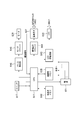
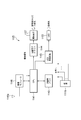
図8は、撮像駆動ユニット部37の機能ブロック図である。撮像駆動ユニット部37は、LED55を駆動するLED駆動回路85と、撮像素子23を駆動する撮像素子ドライバ87と、ステッピングモータ61を駆動するモータドライバ89と、このモータドライバ89に駆動パルスを供給するパルス発生器91と、これらLED駆動回路85、撮像素子ドライバ87、およびパルス発生器91の動作を制御する制御部81と、を制御ユニット45に備えている。また、メモリ83には、制御ユニット45の制御プログラムが格納されている。尚、メモリ83は、制御プログラムを格納するとともに、画像データを格納し、またワークメモリとしても動作しており、制御部81は、撮像素子23から読み出した撮像信号に適宜画像処理を施して画像データを生成し、生成した画像データをメモリ83に格納する。かかる構成によれば、内視鏡1単体で被写体の画像を取得・保存することができ、取り扱い性に優れる。
FIG. 8 is a functional block diagram of the imaging drive unit unit 37. The imaging drive unit 37 supplies an LED drive circuit 85 that drives the LED 55, an image sensor driver 87 that drives the image sensor 23, a motor driver 89 that drives the stepping motor 61, and a drive pulse to the motor driver 89. The control unit 45 includes a pulse generator 91, an LED drive circuit 85, an image sensor driver 87, and a control unit 81 that controls operations of the pulse generator 91. The memory 83 stores a control program for the control unit 45. The memory 83 stores a control program, stores image data, and also operates as a work memory. The control unit 81 appropriately performs image processing on the image pickup signal read from the image pickup device 23 to generate an image. Data is generated, and the generated image data is stored in the memory 83. According to such a configuration, the image of the subject can be acquired and stored by the endoscope 1 alone, and the handleability is excellent.
内視鏡1の電源スイッチ93が閉じられると、電源電池25からの電力が図示しない配線を通して撮像駆動ユニット部37の各部に供給され、撮像が行われる。電源スイッチ93は、例えば、本体部11の底部11aに設けられ、手操作により開閉される構成としても良い。あるいは、本体部11に磁力に応動するスイッチ端子を内蔵させ、内視鏡1の外部から、磁石を近づけたり離したりすることで、このスイッチ端子を開閉操作する構成としても良い。
When the power switch 93 of the endoscope 1 is closed, power from the power supply battery 25 is supplied to each part of the imaging drive unit 37 through a wiring (not shown), and imaging is performed. For example, the power switch 93 may be provided on the bottom 11a of the main body 11 and may be manually opened and closed. Alternatively, a switch terminal that responds to a magnetic force may be built in the main body 11, and the switch terminal may be opened and closed by moving the magnet closer to or away from the outside of the endoscope 1.
次に、内視鏡1の動作について説明する。電源スイッチ93が投入され、電源電池25から各部に電力が供給される。そして、LED55からの照明光が、対物レンズ17および透光性カバー13の円筒部13cを通して側方に照射され、被写体が照明される。
Next, the operation of the endoscope 1 will be described. The power switch 93 is turned on, and power is supplied from the power battery 25 to each unit. And the illumination light from LED55 is irradiated to the side through the objective lens 17 and the cylindrical part 13c of the translucent cover 13, and a to-be-photographed object is illuminated.
被写体からの反射光は、透光性カバー13の円筒部13cおよび対物レンズ17を通して内視鏡1内に取り込まれ、集光レンズ51によって撮像素子23の受光面上に結像される。光電変換により撮像素子23に蓄積された電荷は、制御ユニット45の制御部(CPU)81により撮像信号として読み出される。制御部81は、読み出した撮像信号に適宜画像処理を施して画像データを生成し、生成した画像データをメモリ83に格納する。
Reflected light from the subject is taken into the endoscope 1 through the cylindrical portion 13 c of the translucent cover 13 and the objective lens 17, and is imaged on the light receiving surface of the image sensor 23 by the condenser lens 51. The charge accumulated in the image sensor 23 by the photoelectric conversion is read out as an image signal by the control unit (CPU) 81 of the control unit 45. The control unit 81 appropriately performs image processing on the read imaging signal to generate image data, and stores the generated image data in the memory 83.
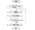
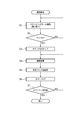
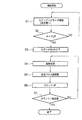
図9は、制御ユニット45の制御プログラムの処理手順を示すフローチャートである。電源スイッチ93が投入されると、先ず、ステッピングモータ61が回転駆動され、レンズホルダ19が、内視鏡1の外殻の中心軸に沿って進み、原点位置にセットされる(ステップS1)。尚、原点位置とは、例えば図5Aに示す位置であって、対物レンズ17が内視鏡1の先端側となる位置とするが、これに限らず、対物レンズ17が反対の基端側となる位置(図5Bに示す位置)であってもよい。
FIG. 9 is a flowchart showing the processing procedure of the control program of the control unit 45. When the power switch 93 is turned on, first, the stepping motor 61 is driven to rotate, and the lens holder 19 advances along the central axis of the outer shell of the endoscope 1 and is set to the origin position (step S1). The origin position is, for example, the position shown in FIG. 5A, and the objective lens 17 is a position on the distal end side of the endoscope 1, but is not limited to this, and the objective lens 17 is on the opposite proximal end side. (The position shown in FIG. 5B).
レンズホルダ19が原点位置にセットされた後、撮像処理を行う(ステップS2)。撮像処理とは、LED55を駆動して照明光を照射し、被写体光を対物レンズ17から内視鏡1内に取り込んで撮像素子23の受光面に結像させ、そして、撮像素子23から読み出した撮像信号をもとに画像データを生成してメモリ83に格納する処理を含む。
After the lens holder 19 is set to the origin position, an imaging process is performed (step S2). In the imaging process, the LED 55 is driven to irradiate illumination light, the subject light is taken into the endoscope 1 from the objective lens 17 to form an image on the light receiving surface of the imaging element 23, and read out from the imaging element 23. This includes processing for generating image data based on the imaging signal and storing it in the memory 83.
次に、指定したパルス数だけステッピングモータ61を駆動し(ステップS3)、レンズホルダ19を所定距離だけ降下させる。レンズホルダ19が最降下位置に達するまでは(ステップS4)、その移動先で撮像処理(ステップS2)を行う。レンズホルダ19が最降下位置に到達したらレンズホルダ19の降下および撮像処理を終了する(ステップS4)。尚、内視鏡1では、メモリ83に格納された複数の画像データを合成して図10に示すような画像マップを作成している(ステップS5)。
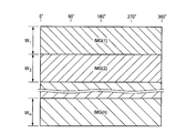
Next, the stepping motor 61 is driven by the designated number of pulses (step S3), and the lens holder 19 is lowered by a predetermined distance. Until the lens holder 19 reaches the lowest lowered position (step S4), the imaging process (step S2) is performed at the moving destination. When the lens holder 19 reaches the lowest lowered position, the lowering of the lens holder 19 and the imaging process are finished (step S4). In the endoscope 1, a plurality of image data stored in the memory 83 is synthesized to create an image map as shown in FIG. 10 (step S5).
図10に示す画像マップにおいて、画像データIMG(1)は、初回に撮像された画像データであり、対物レンズ17が図5Aに示す高さh1にあるときの視野範囲W1の画像データである。また、画像データIMG(2)は、2回目に撮像された画像データであり、対物レンズ17がレンズホルダ19とともに所定距離降下された高さh2にあるときの視野範囲W2の画像データである。
In the image map shown in FIG. 10, image data IMG (1) is image data captured for the first time, and is image data of the visual field range W1 when the objective lens 17 is at the height h1 shown in FIG. 5A. Further, the image data IMG (2) is image data imaged for the second time, and is image data of the visual field range W2 when the objective lens 17 is at a height h2 lowered with the lens holder 19 by a predetermined distance.
このようにレンズホルダ19を移動させて各移動位置で得た複数の画像データIMG(1)~(n)を、その撮像順にレンズホルダ19の移動方向に順次結合して、実質的に一枚の画像データ(画像マップ)にする。尚、例えばステップS3においてステッピングモータ61に供給されるパルス数を適宜調節し、あるいは送りネジ67のネジピッチを適宜調節するなどして、ある回の撮像処理の視野範囲の一部が前回の撮像処理の視野範囲に重なるようにすれば、軸方向に被写体をもれなく撮影でき、隙間のない画像マップを得ることができる。
The plurality of image data IMG (1) to (n) obtained at the respective movement positions by moving the lens holder 19 in this way are sequentially combined in the moving direction of the lens holder 19 in the order of imaging, so that substantially one sheet is obtained. Image data (image map). Note that, for example, by adjusting the number of pulses supplied to the stepping motor 61 in step S3 as appropriate, or by adjusting the screw pitch of the feed screw 67 as appropriate, a part of the visual field range of a certain imaging process is the previous imaging process. If it overlaps with the visual field range, it is possible to capture the subject in the axial direction without fail and to obtain an image map without a gap.
上記の画像マップが作成された後は、この画像マップをメモリ83(図8参照)から外部に読み出すことになる。この読み出しは、無線を用いて行っても良く、また、転送用のケーブルを図1に示す管29内に挿通して撮像駆動ユニット部37に接続し、このケーブルを用いて読み出しても良い。あるいは、メモリ83を内視鏡1から取り出し可能に設けておき、取り出したメモリ83を別置のパーソナルコンピュータで読むようにしても良い。
After the above image map is created, this image map is read out from the memory 83 (see FIG. 8). This reading may be performed by radio, or a transfer cable may be inserted into the tube 29 shown in FIG. 1 and connected to the imaging drive unit unit 37 to read using this cable. Alternatively, the memory 83 may be provided so as to be removable from the endoscope 1, and the extracted memory 83 may be read by a separate personal computer.
また、内視鏡1は、画像データを外部モニタに送り、外部モニタで画像をオンラインで観察できるようにし、更に、外部から操作指示を入力する構成にもできる。その場合には、制御部81は画像処理を行うことなく、撮像素子23から取得した撮像信号をそのまま外部のビデオプロセッサに送り、ビデオプロセッサが画像処理した被写体画像を外部モニタに表示する。外部のビデオプロセッサや外部モニタと制御部81との間の通信は、有線でも無線でも良い。有線で通信を行う場合には、配線中に電源線を入れることで、外部電源を利用することも可能となる。
Also, the endoscope 1 can be configured to send image data to an external monitor so that the image can be observed on-line on the external monitor, and to input an operation instruction from the outside. In that case, the control unit 81 sends the image pickup signal acquired from the image pickup device 23 as it is to the external video processor without performing image processing, and displays the subject image image-processed by the video processor on the external monitor. Communication between the external video processor or external monitor and the control unit 81 may be wired or wireless. In the case of performing wired communication, an external power source can be used by inserting a power line in the wiring.
また、他の制御プログラム例として、図9のフローチャートに示す制御手順の他に、外部からの操作指示に従って、例えば対物レンズ17による視野範囲を、任意の位置に移動させる制御プログラムを用いてもよい。この場合には、撮像目的に応じて所望の部位を選択的に撮像することができ、注目したい部位をより詳細に観察することが可能となる。
As another example of the control program, in addition to the control procedure shown in the flowchart of FIG. 9, for example, a control program for moving the visual field range by the objective lens 17 to an arbitrary position in accordance with an external operation instruction may be used. . In this case, a desired part can be selectively imaged according to the purpose of imaging, and the part to be noticed can be observed in more detail.
上述した内視鏡1によれば、孔に装着された後に、駆動部21により対物レンズ17が軸方向に移動され、それに伴って視野が軸方向に移動する。そのため、操作に熟練を要することなく孔の内周面の画像を広範囲に精度よく取得することができる。
According to the endoscope 1 described above, after being mounted in the hole, the objective lens 17 is moved in the axial direction by the drive unit 21, and accordingly, the visual field is moved in the axial direction. Therefore, the image of the inner peripheral surface of the hole can be acquired with high accuracy over a wide range without requiring skill in operation.
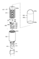
図11~図13に示す電子内視鏡101は、本体部11及び透光性カバー13で構成された外殻を備え、その内部に、透光性カバー13を通して被写体光を集光する対物レンズ群117を保持したレンズホルダ119と、外殻内でレンズホルダ119を移動させる駆動部21と、対物レンズ群117から取り込まれた被写体光を受光して電気信号に変換する固体撮像素子23と、を備えている。尚、上述した内視鏡1と同一の部材には同一符号を付し、また、機能的に共通する部材には相当符号を付すことにより、説明を省略あるいは簡略する。
An electronic endoscope 101 shown in FIGS. 11 to 13 includes an outer shell composed of a main body 11 and a translucent cover 13, and an objective lens that collects subject light through the translucent cover 13 therein. A lens holder 119 that holds the group 117, a drive unit 21 that moves the lens holder 119 within the outer shell, a solid-state imaging device 23 that receives subject light captured from the objective lens group 117 and converts it into an electrical signal, It has. Note that the same members as those of the endoscope 1 described above are denoted by the same reference numerals, and the members that are functionally common are denoted by corresponding reference numerals, and the description thereof is omitted or simplified.
レンズホルダ119は、樹脂材などで形成されており、本体部11に内嵌する円盤状の鍔部33と、鍔部33よりも小径に成形されて透光性カバー13の円筒部13c内に進入可能な筒状部115と、を有している。鍔部33は、本体部11の中心軸、換言すれば外殻の中心軸に沿って本体部11内をガタツキなくスムースに移動できるようになっている。また、筒状部115は、外殻の中心軸に沿って円筒部13c内でガタツキなくスムースに移動できるようになっている。
The lens holder 119 is formed of a resin material or the like. The lens holder 119 is formed into a disc-shaped flange portion 33 that fits inside the main body portion 11. And a cylindrical portion 115 that can enter. The flange 33 can move smoothly in the main body 11 along the central axis of the main body 11, in other words, along the central axis of the outer shell. Moreover, the cylindrical part 115 can move smoothly in the cylindrical part 13c along the central axis of the outer shell without rattling.
内視鏡101において、レンズホルダ119に保持される対物レンズ群117は広角レンズを含んでおり、広角レンズ117Aおよびレンズ117Bで構成されている。広角レンズ117Aとしては、好ましくは魚眼レンズが用いられる。この場合の魚眼レンズとしては、円周魚眼レンズが傾斜角(レンズ光軸からの角度)の大きい全周方向の観察に好適に利用できる。すなわち、本発明の広角レンズは、対物レンズ群117の光軸方向(筒状部115の中心軸方向)に対して側方全周方向の観察が可能な観察視野を有する広角レンズである。なお、広角レンズ117Aとしては、この他にも対角魚眼レンズ、一般的な広角レンズ等を用いることもできる。対物レンズ群117は、そのレンズ光軸をレンズホルダ119の筒状部115の中心軸に一致させ、筒状部115の先端側の開口部に取り付けられている。
In the endoscope 101, the objective lens group 117 held by the lens holder 119 includes a wide-angle lens, and includes a wide-angle lens 117A and a lens 117B. A fish-eye lens is preferably used as the wide-angle lens 117A. As the fisheye lens in this case, the circumferential fisheye lens can be suitably used for observation in the entire circumferential direction having a large inclination angle (angle from the lens optical axis). That is, the wide-angle lens of the present invention is a wide-angle lens having an observation field that allows observation in the entire lateral direction with respect to the optical axis direction of the objective lens group 117 (the central axis direction of the cylindrical portion 115). In addition, as the wide-angle lens 117A, a diagonal fish-eye lens, a general wide-angle lens, or the like can be used. The objective lens group 117 is attached to the opening on the distal end side of the cylindrical portion 115 with its lens optical axis aligned with the central axis of the cylindrical portion 115 of the lens holder 119.
被写体光は、透光性カバー13の円筒部13cを通して対物レンズ群117により集光され、平行光束として外殻の中心軸と平行に筒状部115の中心軸上を進行するようになっている。本体部11内において、レンズホルダ119の筒状部115の中心軸の延長線上にあたる位置には、撮像駆動ユニット部37が配置されている。この撮像駆動ユニット部37、およびレンズホルダ119を移動させる駆動部21は上述した内視鏡1と同一であるので、説明を省略する。
The subject light is collected by the objective lens group 117 through the cylindrical portion 13c of the translucent cover 13, and travels on the central axis of the cylindrical portion 115 as a parallel light beam in parallel with the central axis of the outer shell. . In the main body 11, an imaging drive unit 37 is disposed at a position corresponding to an extension of the central axis of the cylindrical portion 115 of the lens holder 119. Since the imaging drive unit 37 and the drive unit 21 that moves the lens holder 119 are the same as those of the endoscope 1 described above, description thereof is omitted.
次に、内視鏡101の動作について説明する。図8を参照して、電源スイッチ93が投入され、電源電池25から各部に電力が供給される。そして、LED55からの照明光が、対物レンズ群117および透光性カバー13の円筒部13cを通して側方に照射され、被写体が照明される。被写体からの反射光は、透光性カバー13の円筒部13cおよび対物レンズ群117を通して内視鏡1内に取り込まれ、集光レンズ51によって撮像素子23の受光面上に結像される。
Next, the operation of the endoscope 101 will be described. Referring to FIG. 8, power switch 93 is turned on, and power is supplied from power battery 25 to each unit. And the illumination light from LED55 is irradiated to the side through the objective lens group 117 and the cylindrical part 13c of the translucent cover 13, and an object is illuminated. Reflected light from the subject is taken into the endoscope 1 through the cylindrical portion 13 c of the translucent cover 13 and the objective lens group 117, and is imaged on the light receiving surface of the image sensor 23 by the condenser lens 51.
ここで、図14に対物レンズ群117による視野範囲Wの様子を示す。広角レンズ117Aから出射される照明光は、視野範囲Wで示す範囲に照射される。この照明光による被写体からの反射光は、視野範囲Wに入射された光が撮像素子23に結像されて取り込まれる。尚、符号Mは、視野範囲をWに限定するためのマスクである。
Here, FIG. 14 shows a state of the visual field range W by the objective lens group 117. The illumination light emitted from the wide-angle lens 117 </ b> A is applied to the range indicated by the visual field range W. As the reflected light from the subject by the illumination light, the light incident on the field-of-view range W is imaged and captured by the image sensor 23. A symbol M is a mask for limiting the visual field range to W.
そして、光電変換により撮像素子23に蓄積された電荷は、制御ユニット45の制御部(CPU)81により撮像信号として読み出される。制御部81は、読み出した撮像信号に適宜画像処理を施して画像データを生成し、生成した画像データをメモリ83に格納する。
Then, the electric charge accumulated in the image sensor 23 by photoelectric conversion is read out as an image signal by the control unit (CPU) 81 of the control unit 45. The control unit 81 appropriately performs image processing on the read imaging signal to generate image data, and stores the generated image data in the memory 83.
内視鏡101の制御プログラムは、上述した内視鏡1のものと同じであり、図9を参照して、電源スイッチ93が投入されると、先ず、ステッピングモータ61が回転駆動され、レンズホルダ119が、内視鏡1の外殻の中心軸に沿って進み、原点位置にセットされる(ステップS1)。レンズホルダ119が原点位置にセットされた後、撮像処理を行う(ステップS2)。
The control program of the endoscope 101 is the same as that of the endoscope 1 described above. Referring to FIG. 9, when the power switch 93 is turned on, first, the stepping motor 61 is driven to rotate, and the lens holder. 119 advances along the central axis of the outer shell of the endoscope 1 and is set to the origin position (step S1). After the lens holder 119 is set to the origin position, an imaging process is performed (step S2).
次に、指定したパルス数だけステッピングモータ61を駆動し(ステップS3)、レンズホルダ119を所定距離だけ降下させる。尚、所定距離とは、図14に示す視野範囲Wがレンズホルダ119の可動範囲を段だら状に埋めるように、レンズホルダ119をステップ移動させる距離であり、例えば、透光性カバー13の円筒部13cにおいて視野範囲Wに含まれる部分の高さLaとすることができる。
Next, the stepping motor 61 is driven by the designated number of pulses (step S3), and the lens holder 119 is lowered by a predetermined distance. Note that the predetermined distance is a distance by which the lens holder 119 is moved stepwise so that the visual field range W shown in FIG. 14 fills the movable range of the lens holder 119 in a stepped manner, for example, the cylinder of the translucent cover 13. The height La of the portion included in the visual field range W in the portion 13c can be set.
レンズホルダ119が最降下位置に達するまでは(ステップS4)、その移動先で撮像処理(ステップS2)を行う。レンズホルダ119が最降下位置に到達したらレンズホルダ119の降下および撮像処理を終了する(ステップS4)。尚、内視鏡101においても、メモリ83に格納された複数の画像データを合成して図15に示すような画像マップを作成している(ステップS5)。
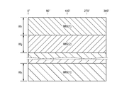
Until the lens holder 119 reaches the lowest position (step S4), the imaging process (step S2) is performed at the moving destination. When the lens holder 119 reaches the lowest lowered position, the lowering of the lens holder 119 and the imaging process are finished (step S4). Also in the endoscope 101, a plurality of image data stored in the memory 83 is synthesized to create an image map as shown in FIG. 15 (step S5).
図15に示す画像マップにおいて、画像データIMG(1)は、初回に撮像された画像データであり、対物レンズ群117が高さh1にあるときの全方位(円周角0°~360°)の視野範囲W1の画像データである。また、画像データIMG(2)は、2回目に撮像された画像データであり、対物レンズ群117がレンズホルダ119とともに所定距離降下された高さh2にあるときの全方位の視野範囲W2の画像データである。このようにレンズホルダ119を移動させて各移動位置で得た複数の画像データIMG(1)~(n)を、その撮像順にレンズホルダ119の移動方向に順次結合して、実質的に一枚の画像データ(画像マップ)にする。
In the image map shown in FIG. 15, the image data IMG (1) is image data captured for the first time, and is omnidirectional (circular angle 0 ° to 360 °) when the objective lens group 117 is at the height h1. Is the image data of the visual field range W1. The image data IMG (2) is image data captured for the second time, and is an image of the omnidirectional visual field range W2 when the objective lens group 117 is at a height h2 lowered by a predetermined distance together with the lens holder 119. It is data. A plurality of pieces of image data IMG (1) to (n) obtained by moving the lens holder 119 in this way at each moving position are sequentially combined in the moving direction of the lens holder 119 in the order of imaging, so that substantially one sheet is obtained. Image data (image map).
内視鏡101によれば、対物レンズ群117に広角レンズ117Aを用いており、内視鏡1に比べて円周方向に関してより広範に撮像することができ、特に魚眼レンズを用いれば全方位について撮像することができる。
According to the endoscope 101, the wide-angle lens 117 </ b> A is used for the objective lens group 117, and a wider range of images can be taken in the circumferential direction compared to the endoscope 1. can do.
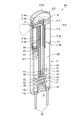
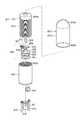
図16~図18に示す電子内視鏡201は、本体部11及び透光性カバー13で構成された外殻を備え、その内部に、透光性カバー13を通して被写体光を集光する対物レンズ17を保持したレンズホルダ219と、外殻内でレンズホルダ219を軸方向に移動させる駆動部221と、対物レンズ17から取り込まれた被写体光を受光して電気信号に変換する固体撮像素子23と、を備えている。上述した内視鏡1と同一の部材には同一符号を付し、また、機能的に共通する部材には相当符号を付すことにより、説明を省略あるいは簡略する。
An electronic endoscope 201 shown in FIGS. 16 to 18 includes an outer shell composed of a main body 11 and a translucent cover 13, and an objective lens that collects subject light through the translucent cover 13 therein. A lens holder 219 that holds the lens 17, a drive unit 221 that moves the lens holder 219 in the axial direction in the outer shell, and a solid-state imaging device 23 that receives subject light captured from the objective lens 17 and converts it into an electrical signal. It is equipped with. The same members as those in the endoscope 1 described above are denoted by the same reference numerals, and the members that are functionally common are denoted by the corresponding reference numerals, thereby omitting or simplifying the description.
レンズホルダ219は、樹脂材などで形成されており、本体部11に内嵌する円盤状の鍔部233と、鍔部233よりも小径に成形されて透光性カバー13の円筒部13c内に進入可能な筒状部215と、を有している。鍔部233は、本体部11の中心軸、換言すれば外殻の中心軸に沿って本体部11内をガタツキなくスムースに移動できるようになっている。また、筒状部215は、外殻の中心軸に沿って円筒部13c内でガタツキなくスムースに移動できるようになっている。
The lens holder 219 is formed of a resin material or the like. The lens holder 219 is formed into a disc-shaped flange portion 233 that fits inside the main body portion 11, and has a smaller diameter than the flange portion 233, and is formed in the cylindrical portion 13 c of the translucent cover 13. And a tubular portion 215 that can enter. The flange 233 can move smoothly in the main body 11 along the central axis of the main body 11, in other words, along the central axis of the outer shell. Moreover, the cylindrical part 215 can move smoothly in the cylindrical part 13c along the central axis of the outer shell without rattling.
筒状部215と鍔部233とは別部材とされており、筒状部215は、鍔部233に組み付けられている。鍔部233の中心部には、円筒状の軸部236が突出して設けられている。筒状部215は、その基端部を軸部236に外嵌させて鍔部233に組み付けられており、軸部236を回転軸に回転自在に支持されている。
The cylindrical part 215 and the flange part 233 are separate members, and the cylindrical part 215 is assembled to the flange part 233. A cylindrical shaft portion 236 protrudes from the center portion of the flange portion 233. The cylindrical portion 215 is assembled to the flange portion 233 with the base end portion fitted on the shaft portion 236, and is supported rotatably on the shaft portion 236 on the rotation shaft.
レンズホルダ219の鍔部233には、その外周面に係合溝35が形成されている。本体部11の内周面には、外殻の軸に沿って延びるリブ31が形成されており、レンズホルダ219は、鍔部233の係合溝235を本体部11のリブ31に係合させている。そのため、レンズホルダ219は、外殻の中心軸に沿って移動を案内され、後述する送りネジ67を回転軸とする回転を止められる。
An engagement groove 35 is formed on the outer peripheral surface of the flange portion 233 of the lens holder 219. A rib 31 extending along the axis of the outer shell is formed on the inner peripheral surface of the main body 11. The lens holder 219 engages the engagement groove 235 of the flange 233 with the rib 31 of the main body 11. ing. Therefore, the lens holder 219 is guided to move along the central axis of the outer shell, and can stop rotating with a feed screw 67 described later as a rotation axis.
筒状部215の先端側には、対物ミラー16が収納されている。そして、筒状部215において対物ミラー16の反射面を径方向に臨む部位には撮像孔が形成されており、この撮像孔に対物レンズ17が設置されている。被写体光は、透光性カバー13の円筒部13cを通して対物レンズ17により集光され、平行光束として対物ミラー16に向けて進行する。そして、被写体光は、対物ミラー16の反射面で反射され、平行光束のまま、外殻の中心軸と平行に筒状部215の中心軸上を進行するようになっている。
The objective mirror 16 is accommodated at the distal end side of the cylindrical portion 215. An imaging hole is formed in a portion of the cylindrical portion 215 facing the reflecting surface of the objective mirror 16 in the radial direction, and the objective lens 17 is installed in the imaging hole. The subject light is collected by the objective lens 17 through the cylindrical portion 13 c of the translucent cover 13 and travels toward the objective mirror 16 as a parallel light flux. The subject light is reflected by the reflecting surface of the objective mirror 16 and travels on the central axis of the cylindrical portion 215 in parallel with the central axis of the outer shell as a parallel light flux.
本体部11内において、レンズホルダ19の筒状部15の中心軸の延長線上にあたる位置には、撮像駆動ユニット部37が配置されている。撮像駆動ユニット部37については、上述した内視鏡1と同一であるので、説明を省略する。
In the main body 11, an imaging drive unit 37 is disposed at a position corresponding to an extension of the central axis of the cylindrical portion 15 of the lens holder 19. Since the imaging drive unit 37 is the same as the endoscope 1 described above, the description thereof is omitted.
レンズホルダ219は、上述のとおり鍔部233の係合溝35を本体部11のリブ31に係合させることにより、外殻の中心軸に沿って移動を案内されている。以下に、レンズホルダ219を外殻の中心軸に沿って移動させる駆動部221について、図18および図19を参照しつつ詳細に説明する。
The lens holder 219 is guided to move along the central axis of the outer shell by engaging the engaging groove 35 of the flange 233 with the rib 31 of the main body 11 as described above. Hereinafter, the drive unit 221 that moves the lens holder 219 along the central axis of the outer shell will be described in detail with reference to FIGS. 18 and 19.
本体部11内には、外殻の中心軸と平行に配置された送りネジ67と、送りネジ67を回転駆動する動力源としてのステッピングモータ61と、が設けられている。ステッピングモータ61の回転軸にはモータギア63が取り付けられ、送りネジ67の一端部にはギア69が取り付けられている。そして、モータギア63とギア69との間に介在して、両ギア63、69にそれぞれ噛み合うアイドルギア65が設けられている。ステッピングモータ61の回転は、モータギア63、アイドルギア65、ギア69を介して送りネジ67に伝達される。
In the main body 11, a feed screw 67 disposed in parallel with the central axis of the outer shell, and a stepping motor 61 as a power source that rotationally drives the feed screw 67 are provided. A motor gear 63 is attached to the rotating shaft of the stepping motor 61, and a gear 69 is attached to one end of the feed screw 67. An idle gear 65 is provided between the motor gear 63 and the gear 69 and meshes with the gears 63 and 69, respectively. The rotation of the stepping motor 61 is transmitted to the feed screw 67 through the motor gear 63, the idle gear 65, and the gear 69.
一方、レンズホルダ219の鍔部233には、ステッピングモータ61、モータギア63、アイドルギア65、送りネジ67、ギア69、等を挿通させることができる通孔73が形成されている。そして、鍔部233の通孔73の周縁部には、送りネジ67に螺合する送りナット75が、ナット押さえ77を用いて取り付けられている。レンズホルダ219は、上述のとおり外殻の中心軸に沿って移動を案内されており、換言すれば、送りネジ67を回転軸とする回転を止められている。そのため、送りネジ67の回転により、この送りネジ67に螺合している送りナット75およびそれを保持するレンズホルダ219は、送りネジ67に沿って、つまりは外殻の中心軸に沿って移動する。
On the other hand, a through hole 73 through which the stepping motor 61, the motor gear 63, the idle gear 65, the feed screw 67, the gear 69, and the like can be inserted is formed in the flange portion 233 of the lens holder 219. A feed nut 75 that is screwed into the feed screw 67 is attached to the peripheral edge portion of the through hole 73 of the flange portion 233 using a nut presser 77. The lens holder 219 is guided to move along the center axis of the outer shell as described above, and in other words, the lens holder 219 is stopped from rotating about the feed screw 67 as a rotation axis. Therefore, by rotation of the feed screw 67, the feed nut 75 screwed into the feed screw 67 and the lens holder 219 that holds the nut move along the feed screw 67, that is, along the central axis of the outer shell. To do.
さらに、駆動部221には、送りネジ67と平行に配置された回転軸268が設けられている。回転軸268は、その外周面に外歯歯車が形成され、送りネジ67に固定されたギア69に噛み合っており、送りネジ67と共にその中心軸まわりに回転する。そして、筒状部215の基端部には、回転軸268に噛み合うギア270が圧入や接着などの適宜な手段により固定されている。送りネジ67が回転するのに伴って、筒状部215のギア270はレンズホルダ219と共に軸方向に移動しながら回転軸268との噛み合いを維持し、筒状部215は、回転軸268およびギア270を介して回転駆動される。
Furthermore, the drive unit 221 is provided with a rotating shaft 268 disposed in parallel with the feed screw 67. The rotating shaft 268 has an external gear formed on the outer peripheral surface thereof, meshes with a gear 69 fixed to the feed screw 67, and rotates around the central axis together with the feed screw 67. A gear 270 that meshes with the rotating shaft 268 is fixed to the base end portion of the cylindrical portion 215 by appropriate means such as press-fitting or adhesion. As the feed screw 67 rotates, the gear 270 of the cylindrical portion 215 moves in the axial direction together with the lens holder 219 while maintaining the meshing with the rotary shaft 268, and the cylindrical portion 215 includes the rotary shaft 268 and the gear. It is rotationally driven via 270.
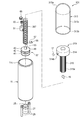
例えば、レンズホルダ219が図20に示す上昇位置にある状態で、ステッピングモータ61を所定の方向に回転駆動し、モータギア63、アイドルギア65、ギア69を介して送りネジ67を回転させる。送りネジ67の回転に伴い、送りナット75が送りネジ67に沿って移動する。それにより、レンズホルダ219を降下させることができる。
For example, with the lens holder 219 in the raised position shown in FIG. 20, the stepping motor 61 is rotationally driven in a predetermined direction, and the feed screw 67 is rotated through the motor gear 63, the idle gear 65, and the gear 69. As the feed screw 67 rotates, the feed nut 75 moves along the feed screw 67. Thereby, the lens holder 219 can be lowered.
そして、図21に示すようにレンズホルダ219がΔhだけ降下する間に、筒状部215が、回転軸268およびギア270を介して所定角度だけ回転駆動される。筒状部215の回転に伴って対物レンズ17もまた回転され、それにより撮像視野が円周方向に移動する。
Then, as shown in FIG. 21, while the lens holder 219 is lowered by Δh, the cylindrical portion 215 is rotated by a predetermined angle via the rotating shaft 268 and the gear 270. As the cylindrical portion 215 rotates, the objective lens 17 is also rotated, and thereby the imaging field of view moves in the circumferential direction.
次に、内視鏡201の動作について説明する。図8を参照して、電源スイッチ93が投入され、電源電池25から各部に電力が供給される。そして、LED55からの照明光が、対物レンズ17および透光性カバー13の円筒部13cを通して側方に照射され、被写体が照明される。被写体からの反射光は、透光性カバー13の円筒部13cおよび対物レンズ17を通して内視鏡201内に取り込まれ、集光レンズ51によって撮像素子23の受光面上に結像される。光電変換により撮像素子23に蓄積された電荷は、制御ユニット45の制御部(CPU)81により撮像信号として読み出される。制御部81は、読み出した撮像信号に適宜画像処理を施して画像データを生成し、生成した画像データをメモリ83に格納する。
Next, the operation of the endoscope 201 will be described. Referring to FIG. 8, power switch 93 is turned on, and power is supplied from power battery 25 to each unit. And the illumination light from LED55 is irradiated to the side through the objective lens 17 and the cylindrical part 13c of the translucent cover 13, and a to-be-photographed object is illuminated. Reflected light from the subject is taken into the endoscope 201 through the cylindrical portion 13 c of the translucent cover 13 and the objective lens 17, and is imaged on the light receiving surface of the image sensor 23 by the condenser lens 51. The charge accumulated in the image sensor 23 by the photoelectric conversion is read out as an image signal by the control unit (CPU) 81 of the control unit 45. The control unit 81 appropriately performs image processing on the read imaging signal to generate image data, and stores the generated image data in the memory 83.
内視鏡201の制御プログラムは、上述した内視鏡1のものと同じであり、図9を参照して、電源スイッチ93が投入されると、先ず、ステッピングモータ61が回転駆動され、レンズホルダ219が、内視鏡201の外殻の中心軸に沿って進み、原点位置にセットされる(ステップS1)。レンズホルダ219が原点位置にセットされた後、撮像処理を行う(ステップS2)。次に、指定したパルス数だけステッピングモータ61を駆動し(ステップS3)、レンズホルダ219を所定距離だけ降下させる。レンズホルダ219が最降下位置に達するまでは(ステップS4)、その移動先で撮像処理(ステップS2)を行う。レンズホルダ219が最降下位置に到達したらレンズホルダ219の降下および撮像処理を終了する(ステップS4)。
The control program of the endoscope 201 is the same as that of the endoscope 1 described above. Referring to FIG. 9, when the power switch 93 is turned on, first, the stepping motor 61 is driven to rotate, and the lens holder 219 advances along the central axis of the outer shell of the endoscope 201 and is set to the origin position (step S1). After the lens holder 219 is set to the origin position, an imaging process is performed (step S2). Next, the stepping motor 61 is driven by the designated number of pulses (step S3), and the lens holder 219 is lowered by a predetermined distance. Until the lens holder 219 reaches the lowest position (step S4), the imaging process (step S2) is performed at the movement destination. When the lens holder 219 reaches the lowest position, the lowering of the lens holder 219 and the imaging process are finished (step S4).
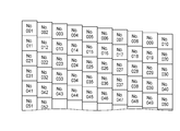
図22は、上記ステップS2~S4を繰り返し実行するときの撮像視野の移動を例示する図である。原点位置で行う初回の撮像処理では、「No.001」の視野で撮像が行われ、撮像素子23から読み出された撮像信号から「No.001」の視野の画像データが生成される。
FIG. 22 is a diagram illustrating the movement of the imaging field when the above steps S2 to S4 are repeatedly executed. In the first imaging process performed at the origin position, imaging is performed in the field of view of “No. 001”, and image data of the field of view of “No. 001” is generated from the imaging signal read from the image sensor 23.
この視野「No.001」での撮像処理が済んだ後、ステップS3で指定パルス数でのステッピングモータ61の駆動が行われ、レンズホルダ219が降下すると共に筒状部215が回転し、次の視野は「No.002」となる。そして、「No.002」の視野で撮像が行われ、撮像素子23から読み出された撮像信号から「No.002」の視野の画像データが生成されることになる。
After the imaging process in the field of view “No. 001” is completed, the stepping motor 61 is driven with the specified number of pulses in step S3, the lens holder 219 is lowered and the cylindrical portion 215 is rotated, and the next step The field of view is “No. 002”. Then, imaging is performed in the field of view of “No. 002”, and image data of the field of view of “No. 002” is generated from the imaging signal read from the image sensor 23.
以後、視野を「No.003」→「No.004」→「No.005」・・・と移動させて撮像処理を繰り返す。筒状部215が原点位置から一周したときの撮像視野は図22の「No.011」となり、二周したときの撮像視野は図22の「No.021」となる。
Thereafter, the field of view is moved in the order of “No. 003” → “No. 004” → “No. 005”. The imaging field of view when the cylindrical portion 215 makes a round from the origin position is “No. 011” in FIG. 22, and the imaging field of view when the cylindrical part 215 makes a round is “No. 021” in FIG.
尚、例えばステップS3においてステッピングモータ61に供給されるパルス数を適宜調節し、あるいは送りネジ67のネジピッチを適宜調節するなどして、円周方向に隣接する撮像視野同士の左右の端部が接し、あるいは若干重なる様に、また、軸方向に隣接する撮像視野同士の上下の端部が接し、あるいは若干重なる様にしてもよい。それによれば、軸方向および円周方向に被写体をもれなく撮影でき、隙間のない画像マップを得ることができる。
For example, in step S3, the right and left ends of the imaging fields adjacent in the circumferential direction are in contact with each other by appropriately adjusting the number of pulses supplied to the stepping motor 61 or by appropriately adjusting the screw pitch of the feed screw 67. Alternatively, the upper and lower ends of the imaging fields adjacent in the axial direction may be in contact with each other or may be slightly overlapped with each other. According to this, it is possible to capture the subject in the axial direction and the circumferential direction without fail, and an image map without a gap can be obtained.
内視鏡201によれば、駆動部221により対物レンズ17が軸方向および円周方向に移動され、それに伴って視野が軸方向および円周方向に移動する。そのため、内視鏡101のように魚眼レンズを用いずとも、全方位について撮像することができる。
According to the endoscope 201, the objective lens 17 is moved in the axial direction and the circumferential direction by the drive unit 221, and accordingly, the visual field is moved in the axial direction and the circumferential direction. Therefore, imaging can be performed in all directions without using a fisheye lens as in the endoscope 101.
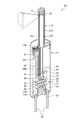
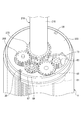
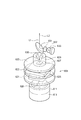
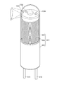
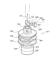
図23~図25に示す電子内視鏡301は、本体部11及び透光性カバー313で構成された外殻を備え、その内部に、透光性カバー313を通して被写体光を集光する対物レンズ17を保持したレンズホルダ319と、外殻内でレンズホルダ319を移動させる駆動部321と、対物レンズ17から取り込まれた被写体光を受光して電気信号に変換する固体撮像素子23と、を備えている。尚、上述した内視鏡1と同一の部材には同一符号を付し、また、機能的に共通する部材には相当符号を付すことにより、説明を省略あるいは簡略する。
An electronic endoscope 301 shown in FIGS. 23 to 25 includes an outer shell composed of a main body 11 and a translucent cover 313, and an objective lens that collects subject light through the translucent cover 313 therein. 17, a lens holder 319 that holds the lens holder 319, a drive unit 321 that moves the lens holder 319 within the outer shell, and a solid-state imaging device 23 that receives subject light captured from the objective lens 17 and converts it into an electrical signal. ing. Note that the same members as those of the endoscope 1 described above are denoted by the same reference numerals, and the members that are functionally common are denoted by corresponding reference numerals, and the description thereof is omitted or simplified.
透光性カバー313は、円筒形に成形されており、一方の端部313bは開口している。透光性カバー313は、この開口端部313bを本体部11の開口端部11cに整合させ、本体部11に固定されている。透光性カバー313の他方の端部(先端部)313aは、被検体の孔への挿入を容易にするために、滑らかな半球状に成形されている。そして、先端部313aと開口端部313bとは、先端部313aと同径に形成された円筒部313cにより接続されている。内視鏡301において、先端部313aおよび円筒部313cは、開口端部313bと同径に成形されている。
The translucent cover 313 is formed in a cylindrical shape, and one end 313b is open. The translucent cover 313 is fixed to the main body 11 with the opening end 313 b aligned with the opening end 11 c of the main body 11. The other end portion (tip portion) 313a of the translucent cover 313 is formed into a smooth hemispherical shape in order to facilitate insertion of the subject into the hole. And the front-end | tip part 313a and the opening edge part 313b are connected by the cylindrical part 313c formed in the same diameter as the front-end | tip part 313a. In the endoscope 301, the distal end portion 313a and the cylindrical portion 313c are formed to have the same diameter as the opening end portion 313b.
上記構成の透光性カバー313は、透明な樹脂材などを用い、例えば一体成形により作製することができるが、少なくとも被検体の孔の内周面を臨む窓部となる円筒部313cが透明に形成されていればよい。
The translucent cover 313 having the above-described configuration can be manufactured by, for example, integral molding using a transparent resin material or the like, but at least the cylindrical portion 313c serving as a window portion facing the inner peripheral surface of the hole of the subject is transparent. It only has to be formed.
レンズホルダ319は、樹脂材などで形成されており、略円盤状に成形された対物レンズ搭載部314と、対物レンズ搭載部314よりも小径の円筒状に成形された筒状部315とを備えている。筒状部315は、その中心軸が、透光性カバー313の中心軸、換言すれば外殻の中心軸と一致するように配置されており、対物レンズ搭載部314は、筒状部315と同軸となるように筒状部315の先端に設けられている。
The lens holder 319 is formed of a resin material or the like, and includes an objective lens mounting portion 314 formed in a substantially disc shape, and a cylindrical portion 315 formed in a cylindrical shape having a smaller diameter than the objective lens mounting portion 314. ing. The cylindrical portion 315 is arranged so that the central axis thereof coincides with the central axis of the translucent cover 313, in other words, the central axis of the outer shell, and the objective lens mounting portion 314 includes the cylindrical portion 315 and the cylindrical portion 315. It is provided at the tip of the cylindrical portion 315 so as to be coaxial.
対物レンズ搭載部314は、その外径が透光性カバー313の円筒部313cの内径よりも若干小径に成形され、透光性カバー313の中心軸、換言すれば外殻の中心軸に沿って透光性カバー313内をガタツキなくスムースに移動できるようになっている。
The outer diameter of the objective lens mounting portion 314 is formed to be slightly smaller than the inner diameter of the cylindrical portion 313c of the translucent cover 313, and along the central axis of the translucent cover 313, in other words, along the central axis of the outer shell. The light-transmitting cover 313 can be moved smoothly without rattling.
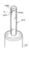
筒状部315の外周面には、外歯歯車315aが形成されている。この外歯歯車315aの歯は、筒状部315の中心軸と平行に延び、周方向に等間隔に形成されている。また筒状部315の内周面には、後述する送りネジ367の外周面に形成されたネジ溝に螺合する雌ネジ315bが形成されている。
An external gear 315 a is formed on the outer peripheral surface of the cylindrical portion 315. The teeth of the external gear 315a extend in parallel with the central axis of the cylindrical portion 315 and are formed at equal intervals in the circumferential direction. Further, on the inner peripheral surface of the cylindrical portion 315, a female screw 315b that is screwed into a screw groove formed on the outer peripheral surface of a feed screw 367 described later is formed.
対物レンズ搭載部314には、筒状部315の先端開口に連なって筒状部315の軸方向に延びる円柱孔314aが形成されており、この円柱孔314a内に、対物ミラー16が収納されている。さらに、対物レンズ搭載部314には、半径方向に延び、一端はその外周面に開口するとともに、他端は対物ミラー16の反射面を径方向に臨むように円柱孔314aに通じる撮像孔314bが形成されており、この撮像孔314bの外周側開口部に対物レンズ17が設置されている。
The objective lens mounting portion 314 has a cylindrical hole 314a that extends in the axial direction of the cylindrical portion 315 and is connected to the opening of the cylindrical portion 315. The objective mirror 16 is accommodated in the cylindrical hole 314a. Yes. Further, the objective lens mounting portion 314 has an imaging hole 314b extending in the radial direction, having one end opened on the outer peripheral surface thereof and the other end communicating with the cylindrical hole 314a so as to face the reflecting surface of the objective mirror 16 in the radial direction. The objective lens 17 is installed at the outer peripheral side opening of the imaging hole 314b.
被写体光は、透光性カバー313の円筒部313cを通して対物レンズ17により集光され、平行光束として対物ミラー16に向けて進行する。そして、被写体光は、対物ミラー16の反射面で反射され、平行光束のまま、筒状部315の中心軸上を、換言すれば外殻の中心軸上を進行するようになっている。
Subject light is collected by the objective lens 17 through the cylindrical portion 313c of the translucent cover 313 and travels toward the objective mirror 16 as a parallel light flux. Then, the subject light is reflected by the reflecting surface of the objective mirror 16 and travels on the central axis of the cylindrical portion 315, in other words, on the central axis of the outer shell as a parallel light flux.
本体部11内において、レンズホルダ319の筒状部315の中心軸の延長線上にあたる位置には、撮像駆動ユニット部37が配置されている。撮像駆動ユニット部37については、上述した内視鏡1と同一であるので、説明を省略する。
In the main body 11, an imaging drive unit 37 is arranged at a position corresponding to an extension of the central axis of the cylindrical portion 315 of the lens holder 319. Since the imaging drive unit 37 is the same as the endoscope 1 described above, the description thereof is omitted.
撮像駆動ユニット部37の基板43には、レンズホルダ319の筒状部315と同軸に送りネジ367が組み付けられている。送りネジ367は、円筒状に成形されており、その内側に集光レンズホルダ49を収容している。そして、送りネジ367は、その外周面にネジ溝が形成されており、このネジ溝を筒状部315の内周面の雌ネジ315bに螺合させて筒状部315内に挿入されている。筒状部315の中心軸上を進む被写体光は、送りネジ367内に進入して集光レンズホルダ49に保持された集光レンズ51に入射し、そして集光レンズ51によって撮像素子23の受光面に結像される。
A feed screw 367 is assembled on the substrate 43 of the image pickup drive unit 37 coaxially with the cylindrical portion 315 of the lens holder 319. The feed screw 367 is formed in a cylindrical shape, and houses the condenser lens holder 49 inside thereof. The feed screw 367 has a screw groove formed on the outer peripheral surface thereof, and is inserted into the cylindrical portion 315 by screwing the screw groove with the female screw 315b on the inner peripheral surface of the cylindrical portion 315. . The subject light traveling on the central axis of the cylindrical portion 315 enters the feed screw 367 and enters the condensing lens 51 held by the condensing lens holder 49, and the condensing lens 51 receives the light from the image sensor 23. The image is formed on the surface.
尚、被写体を照明する光源となるLED55は、送りネジ367の外側に配置されており、LED55の照明光を対物ミラー16に向けて反射するハーフミラー53は、送りネジ367の内側にあって、被写体光の光路途中に配置されている。LED55とハーフミラー53との間に介在する送りネジ367の筒壁には取り付け孔が形成されており、この取り付け孔に照明レンズ57が取り付けられている。LED55の照明光は、照明レンズ57により平行光束とされてハーフミラー53に入射し、少なくともその一部が対物ミラー16に向けて反射される。そして、対物ミラー16に入射した照明光は、対物レンズ17に向けて反射され、対物レンズ17および透光性カバー313を通して被写体に照射される。
The LED 55 serving as a light source for illuminating the subject is disposed outside the feed screw 367, and the half mirror 53 that reflects the illumination light of the LED 55 toward the objective mirror 16 is located inside the feed screw 367. It is arranged in the middle of the optical path of the subject light. An attachment hole is formed in the cylindrical wall of the feed screw 367 interposed between the LED 55 and the half mirror 53, and the illumination lens 57 is attached to this attachment hole. The illumination light of the LED 55 is converted into a parallel light flux by the illumination lens 57 and is incident on the half mirror 53, and at least a part of the illumination light is reflected toward the objective mirror 16. The illumination light incident on the objective mirror 16 is reflected toward the objective lens 17 and is irradiated onto the subject through the objective lens 17 and the translucent cover 313.
ここで、筒状部315を送りネジ367に螺合させたレンズホルダ319は、送りネジ367に沿って、換言すれば外殻の中心軸に沿って移動を案内される。以下に、レンズホルダ319を外殻の中心軸に沿って移動させる駆動部321について、図24を参照しつつ詳細に説明する。
Here, the lens holder 319 in which the cylindrical portion 315 is screwed to the feed screw 367 is guided to move along the feed screw 367, in other words, along the central axis of the outer shell. Hereinafter, the drive unit 321 for moving the lens holder 319 along the central axis of the outer shell will be described in detail with reference to FIG.
本体部11内にはステッピングモータ61が固定されており、また、ステッピングモータ61のモータギア63とレンズホルダ319の筒状部315に形成された外歯歯車315aとの間に介在して、両者にそれぞれ噛み合うアイドルギア65が設けられている。ステッピングモータ61の回転は、モータギア63、アイドルギア65を介してレンズホルダ319に伝達される。
A stepping motor 61 is fixed in the main body 11, and is interposed between a motor gear 63 of the stepping motor 61 and an external gear 315a formed on the cylindrical portion 315 of the lens holder 319. An idle gear 65 that meshes with each other is provided. The rotation of the stepping motor 61 is transmitted to the lens holder 319 via the motor gear 63 and the idle gear 65.
レンズホルダ319は、筒状部315を送りネジ367に外嵌させており、よって、ステッピングモータ61の回転が伝達されたレンズホルダ319は、送りネジ367を回転軸として回転する。同時に筒状部315は、その内周面に形成された雌ネジ315bにより送りネジ367に螺合している。そのため、レンズホルダ319は、送りネジ367を回転軸として回転するのに伴い、送りネジ367に沿って移動する。
The lens holder 319 has the cylindrical portion 315 fitted on the feed screw 367, and thus the lens holder 319 to which the rotation of the stepping motor 61 is transmitted rotates around the feed screw 367 as a rotation axis. At the same time, the cylindrical portion 315 is screwed to the feed screw 367 by a female screw 315b formed on the inner peripheral surface thereof. Therefore, the lens holder 319 moves along the feed screw 367 as it rotates with the feed screw 367 as a rotation axis.
例えば、レンズホルダ319が図26に示す上昇位置にある状態で、ステッピングモータ61を所定の方向に回転駆動し、モータギア63、アイドルギア65を介してレンズホルダ319を回転させる。これにより、図27に示すように、レンズホルダ319は、送りネジ367を回転軸として回転しながら、送りネジ367に沿ってΔhだけ降下する。レンズホルダ319の回転に伴って対物レンズ17もまた回転され、それにより撮像視野が円周方向に移動する。
For example, with the lens holder 319 in the raised position shown in FIG. 26, the stepping motor 61 is rotationally driven in a predetermined direction, and the lens holder 319 is rotated via the motor gear 63 and the idle gear 65. As a result, as shown in FIG. 27, the lens holder 319 descends by Δh along the feed screw 367 while rotating around the feed screw 367 as a rotation axis. With the rotation of the lens holder 319, the objective lens 17 is also rotated, whereby the imaging field of view moves in the circumferential direction.
次に、内視鏡301の動作について説明する。図8を参照して、電源スイッチ93が投入され、電源電池25から各部に電力が供給される。そして、LED55からの照明光が、対物レンズ17および透光性カバー313の円筒部313cを通して側方に照射され、被写体が照明される。被写体からの反射光は、透光性カバー313の円筒部313cおよび対物レンズ17を通して内視鏡301内に取り込まれ、集光レンズ51によって撮像素子23の受光面上に結像される。光電変換により撮像素子23に蓄積された電荷は、制御ユニット45の制御部(CPU)81により撮像信号として読み出される。制御部81は、読み出した撮像信号に適宜画像処理を施して画像データを生成し、生成した画像データをメモリ83に格納する。
Next, the operation of the endoscope 301 will be described. Referring to FIG. 8, power switch 93 is turned on, and power is supplied from power battery 25 to each unit. And the illumination light from LED55 is irradiated to the side through the objective lens 17 and the cylindrical part 313c of the translucent cover 313, and a to-be-photographed object is illuminated. Reflected light from the subject is taken into the endoscope 301 through the cylindrical portion 313 c of the translucent cover 313 and the objective lens 17, and is imaged on the light receiving surface of the image sensor 23 by the condenser lens 51. The charge accumulated in the image sensor 23 by the photoelectric conversion is read out as an image signal by the control unit (CPU) 81 of the control unit 45. The control unit 81 appropriately performs image processing on the read imaging signal to generate image data, and stores the generated image data in the memory 83.
内視鏡301の制御プログラムは、上述した内視鏡1のものと同じであり、図9を参照して、電源スイッチ93が投入されると、先ず、ステッピングモータ61が回転駆動され、レンズホルダ319が、内視鏡301の外殻の中心軸に沿って進み、原点位置にセットされる(ステップS1)。レンズホルダ319が原点位置にセットされた後、撮像処理を行う(ステップS2)。次に、指定したパルス数だけステッピングモータ61を駆動し(ステップS3)、レンズホルダ319を所定距離だけ降下させる。レンズホルダ319が最降下位置に達するまでは(ステップS4)、その移動先で撮像処理(ステップS2)を行う。レンズホルダ319が最降下位置に到達したらレンズホルダ319の降下および撮像処理を終了する(ステップS4)。
The control program of the endoscope 301 is the same as that of the endoscope 1 described above. Referring to FIG. 9, when the power switch 93 is turned on, first, the stepping motor 61 is driven to rotate, and the lens holder. 319 advances along the central axis of the outer shell of the endoscope 301 and is set to the origin position (step S1). After the lens holder 319 is set at the origin position, an imaging process is performed (step S2). Next, the stepping motor 61 is driven by the designated number of pulses (step S3), and the lens holder 319 is lowered by a predetermined distance. Until the lens holder 319 reaches the lowest position (step S4), the imaging process (step S2) is performed at the movement destination. When the lens holder 319 reaches the lowest lowered position, the lowering of the lens holder 319 and the imaging process are finished (step S4).
図28は、上記ステップS2~S4を繰り返し実行するときの撮像視野の移動を例示する図である。原点位置で行う初回の撮像処理では、「No.001」の視野で撮像が行われ、撮像素子23から読み出された撮像信号から「No.001」の視野の画像データが生成される。
FIG. 28 is a diagram illustrating the movement of the imaging field when the above steps S2 to S4 are repeatedly executed. In the first imaging process performed at the origin position, imaging is performed in the field of view of “No. 001”, and image data of the field of view of “No. 001” is generated from the imaging signal read from the image sensor 23.
この視野「No.001」での撮像処理が済んだ後、ステップS3で指定パルス数でのステッピングモータ61の駆動が行われ、レンズホルダ319が降下すると共に回転し、次の視野は「No.002」となる。そして、「No.002」の視野で撮像が行われ、撮像素子23から読み出された撮像信号から「No.002」の視野の画像データが生成されることになる。
After the imaging process in the field of view “No. 001” is completed, the stepping motor 61 is driven with the designated number of pulses in step S3, the lens holder 319 is lowered and rotated, and the next field of view is “No. 002 ". Then, imaging is performed in the field of view of “No. 002”, and image data of the field of view of “No. 002” is generated from the imaging signal read from the image sensor 23.
以後、視野を「No.003」→「No.004」→「No.005」・・・と移動させて撮像処理を繰り返す。レンズホルダ319が原点位置から一周したときの撮像視野は図28の「No.011」となり、二周したときの撮像視野は図28の「No.021」となる。
Thereafter, the field of view is moved in the order of “No. 003” → “No. 004” → “No. 005”. The imaging field of view when the lens holder 319 makes one round from the origin position is “No. 011” in FIG. 28, and the imaging field of view when the lens holder 319 makes two rounds is “No. 021” in FIG.
尚、例えばステップS3においてステッピングモータ61に供給されるパルス数を適宜調節し、あるいは送りネジ367のネジピッチを適宜調節するなどして、円周方向に隣接する撮像視野同士の左右の端部が接し、あるいは若干重なる様に、また、軸方向に隣接する撮像視野同士の上下の端部が接し、あるいは若干重なる様にしてもよい。それによれば、軸方向および円周方向に被写体をもれなく撮影でき、隙間のない画像マップを得ることができる。
Note that, for example, by adjusting the number of pulses supplied to the stepping motor 61 in step S3 or adjusting the screw pitch of the feed screw 367 as appropriate, the left and right ends of the imaging fields adjacent in the circumferential direction are in contact with each other. Alternatively, the upper and lower ends of the imaging fields adjacent in the axial direction may be in contact with each other or may be slightly overlapped with each other. According to this, it is possible to capture the subject in the axial direction and the circumferential direction without fail, and an image map without a gap can be obtained.
内視鏡301によれば、駆動部321により対物レンズ17が軸方向および円周方向に移動され、それに伴って視野が軸方向および円周方向に移動する。そのため、上述した内視鏡101のように魚眼レンズを用いずとも、全方位について撮像することができる。
According to the endoscope 301, the objective lens 17 is moved in the axial direction and the circumferential direction by the driving unit 321, and accordingly, the visual field is moved in the axial direction and the circumferential direction. Therefore, it is possible to capture images in all directions without using a fisheye lens as in the endoscope 101 described above.
図29~図31に示す電子内視鏡401は、本体部11及び透光性カバー313で構成された外殻を備え、その内部に、透光性カバー313を通して被写体光を集光する対物レンズ17を保持したレンズホルダ419と、外殻内でレンズホルダ419を移動させる駆動部421と、対物レンズ17から取り込まれた被写体光を受光して電気信号に変換する固体撮像素子23と、を備えている。尚、上述した内視鏡1,301と同一の部材には同一符号を付し、また、機能的に共通する部材には相当符号を付すことにより、説明を省略あるいは簡略する。
An electronic endoscope 401 shown in FIGS. 29 to 31 includes an outer shell composed of a main body 11 and a translucent cover 313, and an objective lens that collects subject light through the translucent cover 313 therein. 17, a lens holder 419 that holds the lens holder 419, a drive unit 421 that moves the lens holder 419 within the outer shell, and a solid-state image sensor 23 that receives subject light captured from the objective lens 17 and converts it into an electrical signal. ing. Note that the same members as those of the endoscopes 1 and 301 described above are denoted by the same reference numerals, and the members that are functionally common are denoted by the corresponding reference numerals, and the description thereof is omitted or simplified.
レンズホルダ419は、樹脂材などで形成されており、略円盤状に成形された対物レンズ搭載部414と、対物レンズ搭載部414と同径の円筒状に成形された筒状部415とを備えている。筒状部415は、その中心軸が、透光性カバー313の中心軸、換言すれば外殻の中心軸と一致するように配置されており、対物レンズ搭載部414は、筒状部415と同軸となるように筒状部415の先端に設けられている。
The lens holder 419 is formed of a resin material or the like, and includes an objective lens mounting portion 414 formed in a substantially disc shape, and a cylindrical portion 415 formed in a cylindrical shape having the same diameter as the objective lens mounting portion 414. ing. The cylindrical portion 415 is arranged so that the central axis thereof coincides with the central axis of the translucent cover 313, in other words, the central axis of the outer shell, and the objective lens mounting portion 414 includes the cylindrical portion 415 and the cylindrical portion 415. It is provided at the tip of the cylindrical portion 415 so as to be coaxial.
対物レンズ搭載部414および筒状部415は、その外径が透光性カバー313の円筒部313cの内径よりも若干小径に成形され、透光性カバー313の中心軸、換言すれば外殻の中心軸に沿って透光性カバー313内をガタツキなくスムースに移動できるようになっている。
The objective lens mounting portion 414 and the cylindrical portion 415 have outer diameters slightly smaller than the inner diameter of the cylindrical portion 313c of the translucent cover 313, and in other words, the central axis of the translucent cover 313, in other words, the outer shell. The inside of the translucent cover 313 can be smoothly moved along the central axis without rattling.
筒状部415の内周面には、内歯歯車415aが形成されている。この内歯歯車415aの歯は、筒状部415の中心軸と平行に延び、周方向に等間隔に形成されている。また筒状部415の外周面には、本体部11の内周面に形成されたネジ溝に螺合する雄ネジ415bが形成されている。
An internal gear 415 a is formed on the inner peripheral surface of the cylindrical portion 415. The teeth of the internal gear 415a extend in parallel with the central axis of the cylindrical portion 415 and are formed at equal intervals in the circumferential direction. A male screw 415 b that is screwed into a screw groove formed on the inner peripheral surface of the main body portion 11 is formed on the outer peripheral surface of the cylindrical portion 415.
対物レンズ搭載部414には、筒状部415の先端開口に連なって筒状部415の軸方向に延びる円柱孔414aが形成されており、この円柱孔414a内に、対物ミラー16が収納されている。さらに、対物レンズ搭載部414には、半径方向に延び、一端はその外周面に開口するとともに、他端は対物ミラー16の反射面を径方向に臨むように円柱孔414aに通じる撮像孔414bが形成されており、この撮像孔414bの外周側開口部に対物レンズ17が設置されている。
The objective lens mounting portion 414 has a cylindrical hole 414a that extends in the axial direction of the cylindrical portion 415 and is connected to the opening of the cylindrical portion 415. The objective mirror 16 is housed in the cylindrical hole 414a. Yes. Further, the objective lens mounting portion 414 has an imaging hole 414b that extends in the radial direction, one end opens on the outer peripheral surface thereof, and the other end communicates with the cylindrical hole 414a so as to face the reflecting surface of the objective mirror 16 in the radial direction. The objective lens 17 is installed in the outer peripheral side opening of the imaging hole 414b.
被写体光は、透光性カバー313の円筒部313cを通して対物レンズ17により集光され、平行光束として対物ミラー16に向けて進行する。そして、被写体光は、対物ミラー16の反射面で反射され、平行光束のまま、外殻の中心軸と平行に筒状部415の中心軸上を進行するようになっている。
Subject light is collected by the objective lens 17 through the cylindrical portion 313c of the translucent cover 313 and travels toward the objective mirror 16 as a parallel light flux. The subject light is reflected by the reflecting surface of the objective mirror 16 and travels on the central axis of the cylindrical portion 415 in parallel with the central axis of the outer shell as a parallel light flux.
本体部11内において、レンズホルダ419の筒状部415の中心軸の延長線上にあたる位置には、撮像駆動ユニット部37が配置されている。撮像駆動ユニット部37については、上述した内視鏡1と同一であるので、説明を省略する。
In the main body 11, the imaging drive unit 37 is disposed at a position corresponding to an extension of the central axis of the cylindrical portion 415 of the lens holder 419. Since the imaging drive unit 37 is the same as the endoscope 1 described above, the description thereof is omitted.
ここで、筒状部415を本体部11の内周面に形成されたネジ溝に螺合させたレンズホルダ419は、本体部11の中心軸に沿って、換言すれば外殻の中心軸に沿って移動を案内される。以下に、レンズホルダ419を外殻の中心軸に沿って移動させる駆動部421について、図30を参照しつつ詳細に説明する。
Here, the lens holder 419 in which the cylindrical portion 415 is screwed into the thread groove formed on the inner peripheral surface of the main body portion 11 is along the central axis of the main body portion 11, in other words, on the central axis of the outer shell. You will be guided to move along. Below, the drive part 421 which moves the lens holder 419 along the central axis of an outer shell is demonstrated in detail, referring FIG.
本体部11内にはステッピングモータ61が固定されており、また、ステッピングモータ61のモータギア63とレンズホルダ419の筒状部415に形成された内歯歯車415aとの間に介在して、両者にそれぞれ噛み合うアイドルギア65が設けられている。ステッピングモータ61の回転は、モータギア63、アイドルギア65を介してレンズホルダ419に伝達される。
A stepping motor 61 is fixed in the main body 11, and is interposed between the motor gear 63 of the stepping motor 61 and an internal gear 415 a formed on the cylindrical portion 415 of the lens holder 419. An idle gear 65 that meshes with each other is provided. The rotation of the stepping motor 61 is transmitted to the lens holder 419 via the motor gear 63 and the idle gear 65.
レンズホルダ419は、筒状部415を本体部11に内嵌させており、よって、ステッピングモータ61の回転が伝達されたレンズホルダ419は、本体部11の中心軸を回転軸として回転する。同時に筒状部415は、その外周面に形成された雄ネジ415bにより本体部11の内周面に形成されたネジ溝に螺合している。そのため、レンズホルダ419は、本体部11の中心軸を回転軸として回転するのに伴い、本体部11の中心軸に沿って移動する。
The lens holder 419 has a cylindrical portion 415 fitted into the main body 11, and thus the lens holder 419 to which the rotation of the stepping motor 61 is transmitted rotates around the central axis of the main body 11. At the same time, the cylindrical portion 415 is screwed into a screw groove formed on the inner peripheral surface of the main body portion 11 by a male screw 415b formed on the outer peripheral surface thereof. Therefore, the lens holder 419 moves along the central axis of the main body 11 as it rotates with the central axis of the main body 11 as the rotation axis.
例えば、レンズホルダ419が図32に示す上昇位置にある状態で、ステッピングモータ61を所定の方向に回転駆動し、モータギア63、アイドルギア65を介してレンズホルダ419を回転させる。これにより、図33に示すように、レンズホルダ419は、本体部11の中心軸を回転軸として回転しながら、本体部11の中心軸に沿ってΔhだけ降下する。レンズホルダ419の回転に伴って対物レンズ17もまた回転され、それにより撮像視野が円周方向に移動する。
For example, with the lens holder 419 in the raised position shown in FIG. 32, the stepping motor 61 is driven to rotate in a predetermined direction, and the lens holder 419 is rotated via the motor gear 63 and the idle gear 65. As a result, as shown in FIG. 33, the lens holder 419 is lowered by Δh along the central axis of the main body 11 while rotating around the central axis of the main body 11. With the rotation of the lens holder 419, the objective lens 17 is also rotated, thereby moving the imaging field of view in the circumferential direction.
内視鏡401の動作は、上述した内視鏡301と同様であり、駆動部421により対物レンズ17を保持したレンズホルダ419を軸方向および円周方向に逐次移動させながら全方位について撮像する。
The operation of the endoscope 401 is the same as that of the endoscope 301 described above, and images are taken in all directions while the lens holder 419 holding the objective lens 17 is sequentially moved in the axial direction and the circumferential direction by the driving unit 421.
内視鏡401によれば、レンズホルダ419の移動を案内するにあたって、上述した内視鏡301の送りネジ367に替えて本体部11の内周面を用いており、部品点数の削減を図ることができると共に、本体部11の内周面に案内される筒状部415の内側に撮像駆動ユニット部37等を収納することができ、スペースを有効に利用して内視鏡の小型化を図ることができる。
According to the endoscope 401, when guiding the movement of the lens holder 419, the inner peripheral surface of the main body 11 is used instead of the feed screw 367 of the endoscope 301 described above, and the number of parts can be reduced. In addition, the imaging drive unit 37 and the like can be accommodated inside the cylindrical portion 415 guided by the inner peripheral surface of the main body portion 11, and the size of the endoscope can be reduced by effectively using the space. be able to.
以上、電子内視鏡1、101、201、301、401を例に説明したとおり、本明細書には、筒状に形成され、その周壁に軸方向に延びる透明な窓部が設けられた外殻と、前記外殻の内部に設けられた固体撮像素子と、前記窓部を通して被写体光を集光する対物レンズを含み、前記固体撮像素子に結像する対物光学系と、前記対物光学系の少なくとも前記対物レンズを前記外殻の軸に沿って移動させる駆動機構と、を備えたことを特徴とする電子内視鏡が開示されている。
As described above, the electronic endoscope 1, 101, 201, 301, 401 is described as an example. In the present specification, the external endoscope is formed in a cylindrical shape and has a transparent window portion extending in the axial direction on the peripheral wall. A shell, a solid-state imaging device provided inside the outer shell, an objective lens that collects subject light through the window portion, an objective optical system that forms an image on the solid-state imaging device, and an objective optical system An electronic endoscope is disclosed that includes at least a drive mechanism that moves the objective lens along the axis of the outer shell.
また、本明細書には、前記駆動機構が、前記対物レンズを支持するレンズホルダと、前記外殻の軸に沿って延びる送りネジと、前記送りネジを回転駆動するモータと、を備え、前記レンズホルダが、前記送りネジのネジ溝に係合し、且つ前記送りネジを回転軸とした回転を規制されていることを特徴とする電子内視鏡が開示されている。
In the present specification, the drive mechanism includes a lens holder that supports the objective lens, a feed screw that extends along the axis of the outer shell, and a motor that rotationally drives the feed screw, An electronic endoscope is disclosed in which a lens holder is engaged with a thread groove of the feed screw and the rotation about the feed screw as a rotation axis is restricted.
また、本明細書には、前記駆動機構が、前記対物レンズを支持するレンズホルダと、前記外殻の軸に沿って延びる送りネジと、前記送りネジを回転軸として前記レンズホルダを回転駆動するモータと、を備え、前記レンズホルダが、前記送りネジのネジ溝に係合していることを特徴とする電子内視鏡が開示されている。
Further, in the present specification, the driving mechanism rotationally drives the lens holder using a lens holder that supports the objective lens, a feed screw extending along the axis of the outer shell, and the feed screw as a rotation axis. There is disclosed an electronic endoscope comprising: a motor, wherein the lens holder is engaged with a thread groove of the feed screw.
また、本明細書には、前記外殻が円筒状に成形され、その内周面にネジ溝が形成されており、前記駆動部が、前記対物レンズを支持するレンズホルダと、前記外殻の軸を回転軸として前記レンズホルダを回転駆動するモータと、を備え、前記レンズホルダが、前記外殻の前記ネジ溝に係合していることを特徴とする電子内視鏡が開示されている。
Further, in the present specification, the outer shell is formed in a cylindrical shape, a thread groove is formed on an inner peripheral surface thereof, and the driving unit includes a lens holder that supports the objective lens, and the outer shell. An electronic endoscope comprising: a motor that rotationally drives the lens holder about a shaft as a rotation axis, wherein the lens holder is engaged with the screw groove of the outer shell. .
また、本明細書には、前記固体撮像素子から撮像信号を読み出して画像データを生成する制御部と、該画像データを格納するメモリと、を前記外殻内にさらに備えることを特徴とする電子内視鏡が開示されている。
Further, the present specification further includes a control unit that reads out an imaging signal from the solid-state imaging device and generates image data, and a memory that stores the image data in the outer shell. An endoscope is disclosed.
図34~図36に示す電子内視鏡500は、外殻となる本体部511及び透光性カバー513と、本体部511の内部に収納され筒状部515の一端側に広角レンズとなる対物レンズ群517を配置したレンズホルダ519と、透光性カバー513内および本体部511内でレンズホルダ519を対物レンズ群517の光軸方向に移動させる昇降駆動部521と、対物レンズ群517から取り込まれる被写体光を受光して電気信号に変換する撮像素子523と、を備えている。
The electronic endoscope 500 shown in FIGS. 34 to 36 includes a main body portion 511 and a translucent cover 513 that are outer shells, and an objective that is housed inside the main body portion 511 and serves as a wide-angle lens on one end side of the cylindrical portion 515. The lens holder 519 in which the lens group 517 is arranged, the elevating drive unit 521 that moves the lens holder 519 in the optical axis direction of the objective lens group 517 in the translucent cover 513 and the main body 511, and the objective lens group 517. And an imaging element 523 that receives subject light to be converted into an electrical signal.
本体部511は、遮光性を有する樹脂材などで有底円筒形に形成されてなり、底部(図35の下側)511aには筒状の電池収納部511bが設けられ、電源電池525が装着された後に電池収納部511bは電池蓋527によって気密に閉塞されるようになっている。つまり、電源電池525は本体部511に内蔵され、外部から電源供給する必要をなくすことで、本体部に電源供給ケーブルを接続する必要がなくなり、電子内視鏡500自体の取り扱い性を向上している。なお、本体部511は円筒形に限らず、他の筒状、あるいは袋状等の形状であってもよい。
The main body 511 is formed in a cylindrical shape with a bottom made of a light-shielding resin material, etc., and a bottom battery (lower side in FIG. 35) 511a is provided with a cylindrical battery storage 511b, and a power battery 525 is mounted. Thereafter, the battery storage portion 511b is hermetically closed by the battery lid 527. In other words, the power supply battery 525 is built in the main body 511, and by eliminating the need to supply power from the outside, there is no need to connect a power supply cable to the main body, thereby improving the handling of the electronic endoscope 500 itself. Yes. The main body 511 is not limited to a cylindrical shape, and may have another cylindrical shape or a bag shape.
また、底部511aには、図示する例では樹脂製の2本の硬質の配線保護管529が外方へ突出して固定され、この配線保護管529に例えば画像信号等を出力する配線を挿通することが可能となっている。なお、配線保護管529は、内視鏡500を使用する際に、内視鏡500の全体を、被検体となる孔内あるいは体腔内に挿入したり、引き出すための把持管としても利用可能になっている。
In the illustrated example, two hard wiring protective tubes 529 made of resin protrude outward and are fixed to the bottom portion 511a, and a wiring for outputting an image signal or the like is inserted into the wiring protective tube 529, for example. Is possible. The wiring protection tube 529 can also be used as a grasping tube for inserting or withdrawing the entire endoscope 500 into a hole or body cavity as a subject when the endoscope 500 is used. It has become.
本体部511の内周面には、本体部511の長手方向に沿ったリブ531が形成され、レンズホルダ519の鍔部533に形成された係合溝535と係合することで、レンズホルダ519が回転止めされる。
A rib 531 along the longitudinal direction of the main body 511 is formed on the inner peripheral surface of the main body 511 and engages with an engagement groove 535 formed in the flange 533 of the lens holder 519, so that the lens holder 519 is engaged. Is stopped.
透光性カバー513は、硬質の透明樹脂で成形され、先端側の頂部は、被検体内部への挿入を容易にする滑らかな半球状に成形されている。この半球部513aとは反対側の拡径した開口端部513bと、本体部511の開口端部511cとが整合して互いに接着固定される。透光性カバー513は一体成形により作製する他、半球部513a、開口端部511cが接着により接合された構成としてもよい。また、半球部513aに遮光性を持たせて外光が直接対物レンズ群517に導入されることを防止した構成としてもよい。ここで、透明樹脂とは、特定の波長の光に対して透明であればよく、必ずしも可視光に対して透明でなくてもよい。
The translucent cover 513 is formed of a hard transparent resin, and the top on the tip side is formed into a smooth hemisphere that facilitates insertion into the subject. The enlarged opening end 513b opposite to the hemispherical portion 513a and the opening end 511c of the main body 511 are aligned and fixed to each other. The translucent cover 513 may be formed by integral molding, or may be configured such that the hemispherical portion 513a and the open end portion 511c are joined by adhesion. Further, the hemispherical portion 513a may have a light blocking property to prevent external light from being directly introduced into the objective lens group 517. Here, transparent resin should just be transparent with respect to the light of a specific wavelength, and does not necessarily need to be transparent with respect to visible light.
透光性カバー513の半球部513aおよび半球部513aから開口端部513bまでの間の円筒部513cは、本体部511の外形と略同径の開口端部513bよりも小さく形成している。このように、半球部513aおよび円筒部513cを細くすることで、狭い被検体の内部へ容易に挿入することができ、電子内視鏡500の利用範囲を拡げることができる。なお、透光性カバー513の円筒部513cは先細りのテーパ形状としてもよく、このようにすると、小さな孔内,体腔内に透光性カバー513の先端を挿入し易くなる。さらに、半球部513aおよび円筒部513cを本体部511の外形と略等しく形成し、開口端部513bと同一径とした構成にすることも可能である。その場合には、先細の先端が無くなり、電子内視鏡500の強度が向上して堅牢性を高められる。
The translucent cover 513 has a hemispherical portion 513a and a cylindrical portion 513c between the hemispherical portion 513a and the opening end portion 513b that is smaller than the opening end portion 513b having substantially the same diameter as the outer shape of the main body portion 511. As described above, by making the hemispherical portion 513a and the cylindrical portion 513c thinner, the hemisphere portion 513a and the cylindrical portion 513c can be easily inserted into a narrow subject, and the range of use of the electronic endoscope 500 can be expanded. Note that the cylindrical portion 513c of the translucent cover 513 may have a tapered shape, and this makes it easier to insert the tip of the translucent cover 513 into a small hole or body cavity. Further, the hemispherical portion 513a and the cylindrical portion 513c may be formed to be substantially equal to the outer shape of the main body portion 511 and have the same diameter as the opening end portion 513b. In that case, the tapered tip is eliminated, the strength of the electronic endoscope 500 is improved, and the robustness is enhanced.
レンズホルダ519は、樹脂材料等からなり、透光性カバー513の内側面に沿った外表面形状に形成してある。筒状部515の一端側に、対物レンズ群(広角レンズ517Aおよびレンズ517B)を固定して、一端側頂部の開口を閉塞している。広角レンズ517Aとしては、好ましくは魚眼レンズが用いられる。この場合の魚眼レンズとしては、円周魚眼レンズが傾斜角(レンズ光軸からの角度)の大きい全周方向の観察に好適に利用できる。すなわち、広角レンズは、対物レンズ群517の光軸方向(筒状部515の中心軸方向)に対して側方全周方向の観察が可能な観察視野を有する広角レンズである。なお、広角レンズ517Aとしては、この他にも対角魚眼レンズ、一般的な広角レンズ等を用いることもできる。レンズホルダ519に固定された対物レンズ群517の光軸は、レンズホルダ519の筒状部515の中心軸方向に一致させている。そして、レンズホルダ519の筒状部515は、外径が透光性カバー513の円筒部513cの内径より若干小径に形成され、筒状部515が透光性カバー513内でガタツキなくスムースに移動できるようになっている。
The lens holder 519 is made of a resin material or the like, and is formed in an outer surface shape along the inner surface of the translucent cover 513. The objective lens group (the wide-angle lens 517A and the lens 517B) is fixed to one end side of the cylindrical portion 515, and the opening at the one end side top portion is closed. A fish-eye lens is preferably used as the wide-angle lens 517A. As the fisheye lens in this case, the circumferential fisheye lens can be suitably used for observation in the entire circumferential direction having a large inclination angle (angle from the lens optical axis). In other words, the wide-angle lens is a wide-angle lens having an observation field that allows observation in the entire circumferential direction with respect to the optical axis direction of the objective lens group 517 (the central axis direction of the cylindrical portion 515). In addition, as the wide-angle lens 517A, a diagonal fish-eye lens, a general wide-angle lens, or the like can be used. The optical axis of the objective lens group 517 fixed to the lens holder 519 is aligned with the central axis direction of the cylindrical portion 515 of the lens holder 519. The cylindrical portion 515 of the lens holder 519 has an outer diameter that is slightly smaller than the inner diameter of the cylindrical portion 513c of the translucent cover 513, and the cylindrical portion 515 moves smoothly within the translucent cover 513 without rattling. It can be done.
円筒部513cの中心軸を本体部511の底部511a側に延長した先には、撮像駆動ユニット部537が配置されている。撮像駆動ユニット部537は、本体部511の底部511aに設けた電池収納部511bの周壁部を支柱として、図示しないステー部材を用いて本体部511の内部に固定設置される。撮像駆動ユニット部537は、図示する例では3枚の基板541,542,543を備えている。
An imaging drive unit 537 is arranged at the tip of the central axis of the cylindrical portion 513c extending to the bottom 511a side of the main body 511. The imaging drive unit 537 is fixedly installed inside the main body 511 using a stay member (not shown) using a peripheral wall portion of the battery housing 511b provided on the bottom 511a of the main body 511 as a support. The imaging drive unit unit 537 includes three substrates 541, 542, and 543 in the illustrated example.
図37に撮像駆動ユニット部537を含む一部拡大斜視図を示した。最下層(底部511a側)の基板541にはステッピングモータのドライバ回路等を含む制御ユニット545を設け、中層の基板542には撮像画像データを格納する画像メモリ547を設け、上層の基板543には固体撮像素子であるCCD型イメージセンサやCMOS型イメージセンサ等の撮像素子523を配置している。
FIG. 37 shows a partially enlarged perspective view including the image pickup drive unit 537. A control unit 545 including a driver circuit of a stepping motor and the like is provided on the lower layer (bottom 511a side) substrate 541, an image memory 547 for storing captured image data is provided on the middle layer substrate 542, and an upper layer substrate 543 is provided on the upper layer substrate 543. An image sensor 523 such as a CCD image sensor or a CMOS image sensor which is a solid-state image sensor is disposed.
円筒部513cの中心軸を含む基板543中心部には、円筒状に形成された集光レンズホルダ549を配置し、この集光レンズホルダ549の内部に撮像素子523を収納している。そして、集光レンズホルダ549の上端開口部に集光レンズ551を配置することで、中心軸に沿って導光される平行光束(被写体光)L1を、撮像素子523の受光面に集光レンズ551によって結像させている。
In the central part of the substrate 543 including the central axis of the cylindrical part 513c, a condensing lens holder 549 formed in a cylindrical shape is arranged, and the image sensor 523 is accommodated in the condensing lens holder 549. Then, by arranging the condenser lens 551 in the upper end opening of the condenser lens holder 549, the parallel light beam (subject light) L1 guided along the central axis is collected on the light receiving surface of the image sensor 523. 551 forms an image.
また、対物レンズ群517と撮像素子523との間の光路途中にハーフミラー553を配置して、発光体としての発光ダイオード(LED)555からの発光光を、このハーフミラー553の反射により対物レンズ群517に向けて照明光L2として照射している。つまり、ハーフミラー553を、集光レンズ551に入射する平行光束の集光レンズ551の直前部分に、平行光束の光軸(円筒部513cの中心軸)に対して斜め45度に傾斜して配置している。そして、ハーフミラー553に対し照明光が平行光束となるように偏向する照明レンズ557を、LED555とハーフミラー553との間に設けている。ハーフミラー553,照明レンズ557,LED555は、それぞれ適宜な支持部材により本体部511内に固定されている。
Further, a half mirror 553 is disposed in the middle of the optical path between the objective lens group 517 and the image sensor 523, and light emitted from a light emitting diode (LED) 555 serving as a light emitter is reflected by the half mirror 553. The light is emitted toward the group 517 as illumination light L2. That is, the half mirror 553 is disposed at an angle of 45 degrees obliquely with respect to the optical axis of the parallel light beam (the central axis of the cylindrical portion 513c) in the portion immediately before the condensing lens 551 of the parallel light beam incident on the condensing lens 551. is doing. An illumination lens 557 that deflects the illumination light so as to be a parallel light beam with respect to the half mirror 553 is provided between the LED 555 and the half mirror 553. The half mirror 553, the illumination lens 557, and the LED 555 are fixed in the main body 511 by appropriate support members.
ここで、対物レンズ群517を配置したレンズホルダ519の筒状部515は、図38A、図38Bに示すように、透光性カバー513内および本体部511内で、対物レンズ群517の光軸方向(筒状部515の中心軸方向)に移動可能となっている。すなわち、図38Aに示す広角レンズ517Aの高さがh1の位置から、図38Bに示す高さhnの位置まで、自在に設定可能となっている。
Here, as shown in FIGS. 38A and 38B, the cylindrical portion 515 of the lens holder 519 in which the objective lens group 517 is arranged has an optical axis of the objective lens group 517 in the translucent cover 513 and the main body portion 511. It can move in the direction (the central axis direction of the cylindrical portion 515). That is, the height of the wide-angle lens 517A shown in FIG. 38A can be freely set from the position h1 to the height hn shown in FIG. 38B.
このレンズホルダ519の移動手段について、図35、図39A、及び図39Bを参照しつつ詳細に説明する。本体部511の内側には図示しないモータ保持部材が設けられ、このモータ保持部材にステッピングモータ561を取り付けてある。ステッピングモータ561の回転軸は筒状部515の中心軸(平行光束の光軸)と平行にされている。このステッピングモータ561の回転軸にはモータギア(平歯車)563が取り付けられ、モータギア563には平歯車のアイドルギア565が噛合する。そして、アイドルギア565は、送りネジ567の一端側に圧入または接着により固定したギア569と噛合することで、ステッピングモータ561の回転力がモータギア563,アイドルギア565,ギア569を介して送りネジ567に伝達される。なお、アイドルギア565の歯数はモータギア563の歯数より多く、ステッピングモータ561の回転速度を減速してアイドルギア565に伝達するようになっている。ここで、送りネジ567を駆動するステッピングモータ561は、パルス駆動されるモータに限らず、エンコーダを有するサーボモータ等の各種モータ、あるいは他の駆動源を用いることができる。
The moving means of the lens holder 519 will be described in detail with reference to FIGS. 35, 39A, and 39B. A motor holding member (not shown) is provided inside the main body 511, and a stepping motor 561 is attached to the motor holding member. The rotation axis of the stepping motor 561 is parallel to the central axis of the cylindrical portion 515 (the optical axis of the parallel light beam). A motor gear (spur gear) 563 is attached to the rotation shaft of the stepping motor 561, and a spur idle gear 565 meshes with the motor gear 563. The idle gear 565 meshes with a gear 569 fixed to one end of the feed screw 567 by press-fitting or bonding, so that the rotational force of the stepping motor 561 is fed to the feed screw 567 via the motor gear 563, the idle gear 565, and the gear 569. Is transmitted to. Note that the number of teeth of the idle gear 565 is larger than the number of teeth of the motor gear 563, and the rotational speed of the stepping motor 561 is reduced and transmitted to the idle gear 565. Here, the stepping motor 561 for driving the feed screw 567 is not limited to a pulse-driven motor, and various motors such as a servo motor having an encoder, or other drive sources can be used.
送りネジ567は、図40に一部断面図を示すように、透光性カバー513の開口端部513bのフランジ面に形成された軸穴513dに一端側の先端を挿入し、また、送りネジ567の他端側を、撮像駆動ユニット部537の集光レンズホルダ549の側方に設けた支持アーム571に回転自在に支持させている。したがって、送りネジ567は、ステッピングモータ561の回転により回転駆動される。なお、ステッピングモータ561,モータギア563,アイドルギア565,ギア569は、レンズホルダ519の移動によらずに、本体部511内で同じ高さ位置に留まることになる。
As shown in a partial cross-sectional view in FIG. 40, the feed screw 567 has a tip on one end side inserted into a shaft hole 513d formed in the flange surface of the opening end 513b of the translucent cover 513. The other end side of 567 is rotatably supported by a support arm 571 provided on the side of the condenser lens holder 549 of the imaging drive unit unit 537. Accordingly, the feed screw 567 is rotationally driven by the rotation of the stepping motor 561. Note that the stepping motor 561, the motor gear 563, the idle gear 565, and the gear 569 remain at the same height in the main body 511 regardless of the movement of the lens holder 519.
一方、レンズホルダ519の鍔部533には、図39Aに示すレンズホルダ519の上昇位置においてモータギア563,アイドルギア565,ギア569等との干渉を防ぐ開口孔573が穿設されている。そして、送りネジ567に螺合する送りナット575がナット押さえ577を介して鍔部533に固着されている。
On the other hand, an opening hole 573 that prevents interference with the motor gear 563, the idle gear 565, the gear 569, and the like is formed in the collar portion 533 of the lens holder 519 at the raised position of the lens holder 519 shown in FIG. 39A. A feed nut 575 that is screwed to the feed screw 567 is fixed to the flange portion 533 via a nut retainer 577.
上記構成により、送りネジ567と、送りナット575の固定されたレンズホルダ519は、送りネジ567の回転動作によりレンズホルダ519が送りネジ567の軸方向に移動する直線移動機構として機能する。
With the above configuration, the feed screw 567 and the lens holder 519 to which the feed nut 575 is fixed function as a linear movement mechanism in which the lens holder 519 moves in the axial direction of the feed screw 567 by the rotation operation of the feed screw 567.
例えば、図39Aに示すレンズホルダ519の上昇位置からステッピングモータ561を駆動すると、モータギア563,アイドルギア565,ギア569を介して送りネジ567が回転駆動される。送りネジ567が回転駆動されると、これに螺合する送りナット575が送りネジ567に対して相対移動する。これにより、図39Bに示すようにレンズホルダ519を上昇位置から下降させることができる。
For example, when the stepping motor 561 is driven from the raised position of the lens holder 519 shown in FIG. 39A, the feed screw 567 is rotationally driven via the motor gear 563, the idle gear 565, and the gear 569. When the feed screw 567 is driven to rotate, the feed nut 575 that is screwed to the feed screw 567 moves relative to the feed screw 567. Thereby, as shown in FIG. 39B, the lens holder 519 can be lowered from the raised position.
図41は、撮像駆動ユニット部537の機能ブロック図である。システム全体を統括制御する制御部(CPU)581には、制御プログラムが格納されると共にワークメモリとしても動作し、図37で説明した基板542に設けられる画像メモリ547を含むメモリ583と、LED555を駆動するLED駆動回路585と、撮像素子523を駆動する撮像素子ドライバ587と、ステッピングモータ561を駆動するモータドライバ589に駆動パルスを供給するパルス発生器591とが接続される。制御部581が画像処理した後の画像データは、本体部511に内蔵された画像メモリ547に格納されることで、電子内視鏡500単体による画像の取得が行え、取り扱い性を向上できる。
41 is a functional block diagram of the imaging drive unit 537. As shown in FIG. A control unit (CPU) 581 that performs overall control of the entire system stores a control program and also operates as a work memory. A memory 583 including an image memory 547 provided on the board 542 described with reference to FIG. An LED drive circuit 585 for driving, an image sensor driver 587 for driving the image sensor 523, and a pulse generator 591 for supplying a drive pulse to the motor driver 589 for driving the stepping motor 561 are connected. The image data after the image processing by the control unit 581 is stored in the image memory 547 built in the main body unit 511, whereby an image can be acquired by the electronic endoscope 500 alone, and the handling property can be improved.
また、この内視鏡500には、電源スイッチ593が設けられ、この電源スイッチ593が投入されると、電源電池525からの電力が図示しない配線を通して撮像駆動ユニット部537の各構成部に供給され、撮像動作,駆動動作が後述するように行われる。
The endoscope 500 is provided with a power switch 593. When the power switch 593 is turned on, power from the power battery 525 is supplied to each component of the imaging drive unit 537 through a wiring (not shown). The imaging operation and the driving operation are performed as described later.
電源スイッチ593は、例えば、本体部511の底部511aに設けられ、手操作スイッチがオンオフされる構成としても良い。あるいは、本体部511に磁力に応動するスイッチ端子を内蔵させ、内視鏡500の外部から、磁石を近づけたり離したりすることで、このスイッチ端子をオンオフ操作する構成としても良い。
The power switch 593 may be provided, for example, on the bottom 511a of the main body 511 so that the manual operation switch is turned on / off. Alternatively, a switch terminal that responds to a magnetic force may be built in the main body 511, and the switch terminal may be turned on and off by moving the magnet closer to or away from the outside of the endoscope 500.
次に、内視鏡500の動作について説明する。図35,図41に示すように、電源スイッチ593が投入されると、電源電池525から各部に電力が供給されて動作を開始し、ステッピングモータ561が回転駆動される。これにより、レンズホルダ519は、内視鏡500の内部で筒状部515の中心軸方向に進み、原点位置(例えばレンズホルダ519の上昇端位置)で停止する。また、LED555からの発光光が照明レンズ557で平行光とされ、この平行光がハーフミラー553により対物レンズ群517の方向に反射されて、対物レンズ群517を通して筒状部515の中心軸に対して略直交する方向(被検体への挿入方向に対する側面方向)の全周にわたって照射され、照明光となる。
Next, the operation of the endoscope 500 will be described. As shown in FIGS. 35 and 41, when the power switch 593 is turned on, power is supplied from the power battery 525 to each unit to start the operation, and the stepping motor 561 is driven to rotate. Thereby, the lens holder 519 advances in the central axis direction of the cylindrical portion 515 inside the endoscope 500, and stops at the origin position (for example, the rising end position of the lens holder 519). The emitted light from the LED 555 is converted into parallel light by the illumination lens 557, and this parallel light is reflected by the half mirror 553 toward the objective lens group 517 and passes through the objective lens group 517 with respect to the central axis of the cylindrical portion 515. Are irradiated over the entire circumference in a direction substantially orthogonal (side surface direction with respect to the direction of insertion into the subject) to become illumination light.
被写体からの反射光は対物レンズ群517を通して内視鏡500内に取り込まれ、被写体の光像は、平行光束のまま集光レンズ551まで進み、この集光レンズ551によって撮像素子523の受光面上に結像される。ここで、図42に対物レンズ群517による視野範囲Wの様子を示した。広角レンズ517Aから出射される照明光は、視野範囲Wで示す範囲に照射される。この照明光による被写体からの反射光は、視野範囲Wに入射された光が撮像素子523に結像されて取り込まれる。なお、広角レンズ517Aの光軸中央部には、視野範囲Wの上端を決定する遮光マスクMを設けてある。ここでは、広角レンズ517Aの外側表面(光出射側表面)に、半径を視野範囲Wに応じて設定した円形状の遮光マスクMを設けている。
Reflected light from the subject is taken into the endoscope 500 through the objective lens group 517, and the optical image of the subject travels to the condensing lens 551 as a parallel light beam. The condensing lens 551 causes the light on the light receiving surface of the image sensor 523 to travel. Is imaged. Here, FIG. 42 shows a state of the visual field range W by the objective lens group 517. The illumination light emitted from the wide-angle lens 517A is applied to the range indicated by the visual field range W. As the reflected light from the subject due to the illumination light, the light incident on the visual field range W is imaged on the image sensor 523 and captured. A light-shielding mask M that determines the upper end of the visual field range W is provided at the center of the optical axis of the wide-angle lens 517A. Here, a circular light shielding mask M having a radius set according to the field of view range W is provided on the outer surface (light emitting side surface) of the wide-angle lens 517A.
撮像素子523で撮像された被写体の撮像信号は、制御部(CPU)581に入力され画像処理され、例えばJPEG画像データとしてメモリ583(画像メモリ547)に格納される。
The imaging signal of the subject imaged by the imaging element 523 is input to the control unit (CPU) 581 and subjected to image processing, and stored in the memory 583 (image memory 547) as, for example, JPEG image data.
図43は、メモリ583に格納されている制御プログラムの処理手順を示すフローチャートである。電源スイッチ593が投入されると、この制御プログラムが立ち上がり、先ず、ステッピングモータ561が駆動されて、レンズホルダ519を原点位置(上昇端位置)の方向に移動する(S1)。原点位置とは、例えば図34、図38Aに示すように、対物レンズ群517の位置が内視鏡500の先端側となる位置とするが、これに限らず、先端側とは反対の基端側(図38Bに示すレンズホルダの位置)であってもよい。
FIG. 43 is a flowchart showing the processing procedure of the control program stored in the memory 583. When the power switch 593 is turned on, this control program is started up. First, the stepping motor 561 is driven to move the lens holder 519 in the direction of the origin position (rising end position) (S1). For example, as shown in FIGS. 34 and 38A, the origin position is a position where the position of the objective lens group 517 is the distal end side of the endoscope 500, but is not limited thereto, and is the base end opposite to the distal end side. It may be the side (the position of the lens holder shown in FIG. 38B).
レンズホルダ519が原点位置に到達した後、撮像処理を行う(S2)。撮像処理とは、LED555を点灯して対物レンズ群517から照明光を照射し、被写体から反射した光を対物レンズ群517から内視鏡500内に取り込み、撮像素子523の受光面に結像させる処理と、撮像素子523から撮像信号を生成させ、この被写体の撮像信号を画像処理してメモリ583(画像メモリ547)に格納する処理とを含む。
After the lens holder 519 reaches the origin position, an imaging process is performed (S2). In the imaging process, the LED 555 is turned on to irradiate illumination light from the objective lens group 517, and the light reflected from the subject is taken into the endoscope 500 from the objective lens group 517 and imaged on the light receiving surface of the imaging element 523. Processing, and processing for generating an imaging signal from the imaging element 523, subjecting the imaging signal of the subject to image processing, and storing it in the memory 583 (image memory 547).
次に、指定したパルス数だけステッピングモータ561を駆動し(S3)、レンズホルダ519を所定距離だけ下降させる。所定距離とは、図42に示す視野範囲Wがレンズホルダ519の可動範囲を段だら状に埋めるように、レンズホルダ519をステップ移動させる距離であり、例えば、透光性カバー513の円筒部513cにおいて視野範囲Wに含まれる部分の高さLaとすることができる。
Next, the stepping motor 561 is driven by the designated number of pulses (S3), and the lens holder 519 is lowered by a predetermined distance. The predetermined distance is a distance by which the lens holder 519 is moved stepwise so that the visual field range W shown in FIG. 42 fills the movable range of the lens holder 519 stepwise. For example, the cylindrical portion 513c of the translucent cover 513 is used. , The height La of the portion included in the visual field range W can be set.
移動先がレンズホルダ519の最下降位置に達するまでは(S4)、その移動先で撮像処理(S2)を行う。S2およびS3を繰り返し行って、図44に示すような画像マップを各回の撮像画像を合成することで生成する(S5)。つまり、初回の撮像画像データIMG(1)は、対物レンズ群517の広角レンズ517Aの高さが図38Aに示す高さh1の位置にあるときの全周方向(円周角0°~360°)の視野範囲W1の画像データであり、2回目の撮像画像データIMG(2)は、広角レンズ517Aが高さh1の位置からレンズホルダ519とともに所定距離降下された高さh2の位置にあるときの全周方向の視野範囲W2の画像データである。このようにレンズホルダ519を移動させて各移動位置で得た複数枚の撮像画像データIMG(1)~(n)を、高さ方向に相互に結合することで、実質的に一枚の画像データ(画像マップ)にする。なお、一回の撮影分の視野範囲の一部が次回撮影分の視野範囲と重なるようにすると、画像同士の接続領域がもれなく撮影でき、隙間のない画像データを得ることができる。
Until the movement destination reaches the lowest position of the lens holder 519 (S4), the imaging process (S2) is performed at the movement destination. S2 and S3 are repeated, and an image map as shown in FIG. 44 is generated by synthesizing the captured images of each time (S5). That is, the first picked-up image data IMG (1) is obtained when the height of the wide-angle lens 517A of the objective lens group 517 is at the position of the height h1 shown in FIG. 38A (circumferential angle 0 ° to 360 °). ) And the second picked-up image data IMG (2) is obtained when the wide-angle lens 517A is at a position of a height h2 that is lowered by a predetermined distance together with the lens holder 519 from the position of the height h1. The image data of the visual field range W2 in the entire circumferential direction. The plurality of captured image data IMG (1) to (n) obtained at each moving position by moving the lens holder 519 in this manner are coupled to each other in the height direction, so that substantially one image is obtained. Data (image map). If a part of the field of view for one shooting overlaps the field of view for the next shooting, the connection area between the images can be captured without any gaps, and image data without gaps can be obtained.
上記の撮像画像データIMG(1)~(n)による画像マップを作成した後は、この画像マップの格納されたメモリ583(図41参照)から、蓄積されたデータを外部に読み出すことになる。この読み出しは、無線を用いて行っても良く、また、図34に示す配線保護管529内に挿通した配線を用いて読み出しても良い。あるいは、メモリ583を内視鏡500から取り出し可能に設けておき、取り出したメモリ583を別置のパーソナルコンピュータで読むようにしても良い。
After creating the image map using the above-described captured image data IMG (1) to (n), the accumulated data is read out from the memory 583 (see FIG. 41) in which the image map is stored. This reading may be performed using radio, or may be performed using wiring inserted into the wiring protection tube 529 shown in FIG. Alternatively, the memory 583 may be provided so as to be removable from the endoscope 500, and the extracted memory 583 may be read by a separate personal computer.
また、内視鏡500は、撮像画像データを外部モニタに送り、外部モニタで撮像画像をオンラインで観察できるようにし、更に、外部から操作指示を入力する構成にもできる。その場合には、制御部581は画像処理を行うことなく、撮像素子523から取得した撮像信号をそのまま外部のビデオプロセッサに送り、ビデオプロセッサが画像処理した被写体画像を外部モニタに表示する。外部のビデオプロセッサや外部モニタと制御部581との間の通信は、有線でも無線でも良い。有線で通信を行う場合には、配線中に電源線を入れることで、外部電源を利用することも可能となる。
Also, the endoscope 500 can be configured to send captured image data to an external monitor so that the captured image can be observed on-line on the external monitor and to input an operation instruction from the outside. In that case, the control unit 581 sends the image signal acquired from the image sensor 523 to the external video processor as it is without performing image processing, and displays the subject image image-processed by the video processor on the external monitor. Communication between the external video processor or external monitor and the control unit 581 may be wired or wireless. When performing wired communication, an external power source can be used by inserting a power line in the wiring.
また、他の制御プログラム例として、図43のフローチャートに示す制御手順の他に、外部からの操作指示に従って、例えば対物レンズ群517による視野範囲を、任意の位置に移動させる制御プログラムを用いてもよい。この場合には、撮像目的に応じて所望の部位を選択的に撮像することができ、注目したい部位をより詳細に観察することが可能となる。
As another control program example, in addition to the control procedure shown in the flowchart of FIG. 43, for example, a control program that moves the visual field range by the objective lens group 517 to an arbitrary position in accordance with an external operation instruction may be used. Good. In this case, a desired part can be selectively imaged according to the purpose of imaging, and the part to be noticed can be observed in more detail.
以上、電子内視鏡500を例に説明したとおり、本明細書には、被検体の内部に挿入して被検体内を撮像する電子内視鏡であって、筒状部を有するレンズホルダと、前記レンズホルダに装着され、前記筒状部の一端側に、該筒状部の中心軸に光軸を合わせて配置し、前記筒状部の側方まで観察視野が広がる広角レンズと、前記広角レンズから取り込まれる光を受光し電気信号に変換する撮像素子と、前記筒状部の一端側を覆い、少なくとも前記広角レンズの観察視野内に対面する部位が透光性を有する透光性カバーと、前記筒状部の他端側で前記透光性カバーと接続される筒状の本体部と、前記本体部内に配置され前記レンズホルダを前記中心軸方向に進退させる駆動部と、を備えたことを特徴とする電子内視鏡が開示されている。
As described above, as described with the electronic endoscope 500 as an example, the present specification describes an electronic endoscope that is inserted into a subject and images the inside of the subject, and includes a lens holder having a cylindrical portion, A wide-angle lens that is attached to the lens holder and is arranged on one end side of the cylindrical portion with the optical axis aligned with the central axis of the cylindrical portion, and the observation field of view extends to the side of the cylindrical portion; An image sensor that receives light taken from a wide-angle lens and converts it into an electrical signal, and a translucent cover that covers one end of the cylindrical portion and has a translucency at least facing the viewing field of the wide-angle lens And a cylindrical main body connected to the translucent cover on the other end side of the cylindrical portion, and a drive unit disposed in the main body for moving the lens holder forward and backward in the central axis direction. An electronic endoscope characterized by the above is disclosed.
この電子内視鏡によれば、透光性カバー内のレンズホルダが駆動部によって進退移動することで、レンズホルダの筒状部の中心軸上で異なる位置から撮像が可能となり、広角レンズから取り込まれる画像情報を、レンズホルダの移動範囲内で精度良く取得することができる。これにより、電子内視鏡を被検体内で移動させることなく、広範囲の連続した画像を簡単に取得することができる。
According to this electronic endoscope, the lens holder in the translucent cover is moved forward and backward by the drive unit, so that images can be taken from different positions on the central axis of the cylindrical portion of the lens holder and taken in from the wide-angle lens. The acquired image information can be accurately acquired within the moving range of the lens holder. Thereby, it is possible to easily acquire a wide range of continuous images without moving the electronic endoscope within the subject.
また、本明細書には、前記撮像素子が、前記被検体への挿入方向の側方全周からの光を受光することを特徴とする電子内視鏡が開示されている。
Further, the present specification discloses an electronic endoscope in which the imaging element receives light from the entire side circumference in the insertion direction of the subject.
この電子内視鏡によれば、被検体への挿入方向の側方全周分の画像情報を取り込むことで、この画像情報を合成して、一枚の側方全周画像を簡単に生成することができる。
According to this electronic endoscope, it is possible to easily generate a single lateral all-round image by synthesizing this image information by capturing image information for the entire lateral circumference in the insertion direction into the subject.
また、本明細書には、前記広角レンズが円周魚眼レンズであることを特徴とする電子内視鏡が開示されている。
Further, the present specification discloses an electronic endoscope in which the wide-angle lens is a circumferential fisheye lens.
この電子内視鏡によれば、円周魚眼レンズを用いることで、広角レンズの光軸の側方全周の画像が効率良く得られ、しかも、被検体の観察表面に対して略垂直方向からの撮像が可能となる。
According to this electronic endoscope, by using a circumferential fisheye lens, an image of the entire circumference of the side of the optical axis of the wide-angle lens can be efficiently obtained, and imaging from a substantially vertical direction with respect to the observation surface of the subject can be performed. It becomes possible.
また、本明細書には前記広角レンズと前記撮像素子との間の光路途中に配置したハーフミラーと、発光した照明光を前記ハーフミラーの反射により前記広角レンズへ照射することで被検体を照明する発光体と、を備えることを特徴とする電子内視鏡が開示されている。
Further, in the present specification, a subject is illuminated by irradiating the wide-angle lens with a half mirror disposed in the middle of the optical path between the wide-angle lens and the image sensor and the emitted illumination light by reflection of the half-mirror. An electronic endoscope characterized in that the electronic endoscope is provided.
この電子内視鏡によれば、発光体からの発光光がハーフミラーにより被検体の方向に反射して、これが被検体の側方全周を照らす照明光となる。
According to this electronic endoscope, the light emitted from the light emitter is reflected in the direction of the subject by the half mirror, and this becomes illumination light that illuminates the entire circumference of the subject.
また、本明細書には、前記レンズホルダの筒状部、および前記透光性カバーの前記筒状部を覆う先端部が、前記本体部より細径に形成されたことを特徴とする電子内視鏡が開示されている。
Further, in the present specification, the inner part of the electronic device is characterized in that a cylindrical part of the lens holder and a tip part covering the cylindrical part of the translucent cover are formed with a diameter smaller than that of the main body part. An endoscope is disclosed.
この電子内視鏡によれば、本体部よりも細径にされた先端部から画像情報を取得するので、被検体の狭い領域に対しても挿入が容易になり、被検体内を観察することができる。もって電子内視鏡の適用可能範囲を拡げることができる。
According to this electronic endoscope, since image information is acquired from a tip portion that is thinner than the main body, insertion is easy even in a narrow region of the subject, and the inside of the subject can be observed. Can do. Accordingly, the applicable range of the electronic endoscope can be expanded.
また、本明細書には、前記駆動部が、前記本体部内で前記広角レンズの光軸方向と平行に回転自在に支持された送りネジと、該送りネジに螺合して前記レンズホルダに固着された送りナットと、前記送りネジを回転駆動するモータと、を有することを特徴とする電子内視鏡が開示されている。
Further, in the present specification, the drive unit is fixed to the lens holder by being screwed into the feed screw that is rotatably supported in the main body unit in parallel with the optical axis direction of the wide-angle lens. An electronic endoscope is disclosed that includes a feed nut and a motor that rotationally drives the feed screw.
この電子内視鏡によれば、モータにより送りネジを回転駆動することで、送りネジに螺合した送りナットが送りネジの軸方向に移動して、これによりレンズホルダを広角レンズの光軸方向と平行に進退移動させることができる。
According to this electronic endoscope, when the feed screw is rotationally driven by a motor, the feed nut that is screwed to the feed screw moves in the axial direction of the feed screw, thereby moving the lens holder in the optical axis direction of the wide-angle lens. Can be moved back and forth in parallel.
また、本明細書には、前記撮像素子が撮像して得た画像信号を画像処理する制御部と、該制御部が画像処理した画像データを格納する画像メモリと、を前記本体部に内蔵することを特徴とする電子内視鏡が開示されている。
Further, in the present specification, a main body unit includes a control unit that performs image processing on an image signal obtained by imaging by the image sensor, and an image memory that stores image data processed by the control unit. An electronic endoscope characterized by this is disclosed.
この電子内視鏡によれば、制御部が画像処理した後の画像データを、本体部に内蔵された画像メモリに格納することで、電子内視鏡単体による画像の取得が行え、取り扱い性を向上できる。
According to this electronic endoscope, the image data after the image processing by the control unit is stored in the image memory built in the main body unit, so that the image can be acquired by the single electronic endoscope and the handling property is improved. Can be improved.
また、本明細書には、前記撮像素子及び前記駆動部に電力を供給する電源電池を、前記本体部に内蔵することを特徴とする電子内視鏡が開示されている。
Further, the present specification discloses an electronic endoscope characterized in that a power supply battery that supplies power to the image pickup device and the drive unit is built in the main body unit.
この電子内視鏡によれば、電源電池が本体部に内蔵されることで、外部から電源供給する必要がなく、従って本体部外から電源供給ケーブルを接続する必要がなくなり、取り扱い性を向上できる。
According to this electronic endoscope, since the power supply battery is built in the main body, it is not necessary to supply power from the outside, and therefore it is not necessary to connect a power supply cable from the outside of the main body, thereby improving handling. .
図45に示す電子内視鏡601は、側視型ということができ、また、硬性型である。この電子内視鏡601は、外殻となる本体部602及び透明カプセル部(透光性カバー)603と、内部に収納される移動レンズ枠部(レンズホルダ)604及び後述の撮像駆動ユニット部605とを備えて構成される。
45 can be referred to as a side view type, and is a rigid type. The electronic endoscope 601 includes a main body portion 602 and a transparent capsule portion (translucent cover) 603 serving as an outer shell, a moving lens frame portion (lens holder) 604 housed inside, and an imaging drive unit portion 605 described later. And is configured.
図46は、電子内視鏡601の分解斜視図であり、図47は、電子内視鏡601の縦断面図である。
46 is an exploded perspective view of the electronic endoscope 601, and FIG. 47 is a longitudinal sectional view of the electronic endoscope 601.
本体部602は、樹脂材などで有底円筒形に形成されて成り、底部(図46の下側)602aには筒状の電池収納部602bが設けられ、電源電池611が装着された後に電池収納部602bは電池蓋612によって気密に閉塞される様になっている。つまり、電子内視鏡601は、電源電池611を内蔵しており、外部からの電力供給を要しない。そのため、電子内視鏡601は、電力供給用のケーブルが接続される必要はなく、取り扱い性に優れる。
The main body 602 is formed in a bottomed cylindrical shape with a resin material or the like, and a cylindrical battery storage portion 602b is provided on the bottom (lower side in FIG. 46) 602a, and the battery after the power battery 611 is mounted. The storage portion 602b is hermetically closed by the battery lid 612. In other words, the electronic endoscope 601 has a built-in power supply battery 611 and does not require external power supply. Therefore, the electronic endoscope 601 does not need to be connected with a power supply cable, and is excellent in handleability.
また、底部602aには、図示する例では樹脂製の2本の硬質の把持管613,614が外部に対して突設固定され、この把持管613,614を持って操作することで、電子内視鏡601の全体を、被検体となる孔内あるいは体腔内に挿入し引き出すことが可能になっている。把持管613,614内に、配線を挿通して電子内視鏡601を使用する場合もある。
In addition, in the illustrated example, two hard grip tubes 613 and 614 made of resin are projected and fixed to the outside on the bottom portion 602a, and by operating with the grip tubes 613 and 614, an electronic internal The entire endoscope 601 can be inserted into and extracted from a hole or body cavity serving as a subject. In some cases, the electronic endoscope 601 is used by inserting wiring into the gripping tubes 613 and 614.
本体部602の内周面には、本体部602の軸を中心とする精密な雌ネジ602cが刻設されており、雄ネジが形成された移動レンズ枠部604が螺合し回転することで、該部材604は、軸方向に進退する様になっている。
A precise female screw 602c centering on the axis of the main body 602 is engraved on the inner peripheral surface of the main body 602, and the moving lens frame 604 on which the male screw is formed is screwed and rotated. The member 604 advances and retreats in the axial direction.
透明カプセル部603は、硬質の透明樹脂で成形された円筒体でなり、一端側(先端側)は半球状に成形され、この半球部603aとは反対側の開口端部603bと、本体部602の開口端部602dとが整合して接着固定される。図示する例では、カプセル部603全体が透明樹脂で形成されているが、円筒部603cの少なくとも観察窓となる部分が透明であればよく、半球部603aは、不透明であってもよい。観察窓とは、後述する対物レンズ617が移動レンズ枠部の回転,移動に伴って対面する部分である。また、半球部603aと円筒部603cとを同一の材料で一体形成せずに別体で形成し一体に接合する構造でもよい。なお、透明樹脂は、例えば赤外光等の特定の波長の光に対して透明であればよく、必ずしも可視光に対して透明でなくてもよい。
The transparent capsule portion 603 is a cylindrical body formed of a hard transparent resin, one end side (tip side) is formed in a hemispherical shape, an opening end portion 603b opposite to the hemispherical portion 603a, and a main body portion 602. Are aligned and fixed to the open end 602d. In the illustrated example, the entire capsule portion 603 is formed of a transparent resin. However, at least a portion of the cylindrical portion 603c that serves as an observation window may be transparent, and the hemispherical portion 603a may be opaque. The observation window is a portion where an objective lens 617, which will be described later, faces as the moving lens frame rotates and moves. Alternatively, the hemispherical portion 603a and the cylindrical portion 603c may be formed separately from each other instead of being integrally formed of the same material. In addition, the transparent resin should just be transparent with respect to the light of specific wavelengths, such as infrared light, for example, and does not necessarily need to be transparent with respect to visible light.
半球部603aを図示するより更に小径に形成し、透明カプセル部603の円筒部603cの先端部をテーパ形状に絞ってから滑らかに半球部603aに連設する様に構成しても良い。この様にすると、より小さな孔内,体腔内にも透明カプセル部603の先端部を案内し挿入し易くなる。透明カプセル部603の円筒部603cの外径と本体部602の外径とを全く同一寸法にしているため、両者間に段差は生じない。
The hemispherical portion 603a may be formed to have a smaller diameter than illustrated, and the tip of the cylindrical portion 603c of the transparent capsule portion 603 may be smoothly connected to the hemispherical portion 603a after narrowing to a tapered shape. In this way, it becomes easy to guide and insert the distal end portion of the transparent capsule portion 603 into smaller holes and body cavities. Since the outer diameter of the cylindrical portion 603c of the transparent capsule portion 603 and the outer diameter of the main body portion 602 are exactly the same, no step is generated between them.
移動レンズ枠部604は、樹脂材を円盤状に形成した対物レンズ搭載部604aと、該対物レンズ搭載部604aと略同径の円筒状部材604bとを備え、円筒状部材604bの上部(電子内視鏡601の先端方向)開口端に対物レンズ搭載部604aが一体となるように接着固定され、該開口端が閉塞される。対物レンズ搭載部604aの外径は、透明カプセル部603の内径より若干小径に形成され、対物レンズ搭載部604aが透明カプセル部603内でガタツキなくスムースに移動できるようになっている。
The moving lens frame portion 604 includes an objective lens mounting portion 604a in which a resin material is formed in a disk shape, and a cylindrical member 604b having substantially the same diameter as the objective lens mounting portion 604a. The objective lens mounting portion 604a is bonded and fixed so as to be integrated with the opening end of the endoscope 601), and the opening end is closed. The outer diameter of the objective lens mounting portion 604a is formed to be slightly smaller than the inner diameter of the transparent capsule portion 603, and the objective lens mounting portion 604a can be smoothly moved within the transparent capsule portion 603 without rattling.
円筒状部材604bの外周面には、本体部602の内周面に刻設された雌ネジ602cに螺合する精密な雄ネジ604cが、円筒状部材604bの軸方向全長に渡って刻設されており、また、円筒状部材604bの内周面には内歯歯車604dが形成されている。この内歯歯車604dは、軸に平行な歯で且つ円筒状部材604bの軸方向全長に渡る歯が周方向に等間隔に形成されてなる。
On the outer peripheral surface of the cylindrical member 604b, a precise male screw 604c that is screwed into a female screw 602c engraved on the inner peripheral surface of the main body 602 is engraved over the entire axial length of the cylindrical member 604b. An internal gear 604d is formed on the inner peripheral surface of the cylindrical member 604b. The internal gear 604d has teeth that are parallel to the axis and that extend over the entire axial length of the cylindrical member 604b at equal intervals in the circumferential direction.
対物レンズ搭載部604aの中心軸部分には、上端方向(電子内視鏡601の先端方向)に底部を有する円柱孔604eが穿孔されており、この円柱孔604e内に、対物ミラー616が収納されている。対物ミラー616は円柱状ガラス体を斜め45度で切断した形状を持ち、この斜め45度の切断面に、反射膜が製膜されている。
A cylindrical hole 604e having a bottom in the upper end direction (the distal direction of the electronic endoscope 601) is drilled in the central axis portion of the objective lens mounting portion 604a, and the objective mirror 616 is accommodated in the cylindrical hole 604e. ing. The objective mirror 616 has a shape obtained by cutting a cylindrical glass body at an angle of 45 degrees, and a reflective film is formed on the cut surface at an angle of 45 degrees.
対物レンズ搭載部604aには、円盤状部材の半径方向に直状に延びる撮像用の撮像孔604fが穿孔され、撮像孔604fの一端は対物レンズ搭載部604aの外周側面に開口され、この開口部に凹レンズでなる対物レンズ617が設けられる。撮像孔604fの他端は円柱孔604eに開口しており、対物レンズ617を通して孔604f内に入射した被写体光は、平行光束として進み、対物ミラー616の上記斜め45度の反射面で反射し、平行光束のまま円筒状部材604bの中心軸に沿って進む様になっている。
The objective lens mounting portion 604a has an imaging hole 604f for imaging that extends straight in the radial direction of the disk-shaped member, and one end of the imaging hole 604f is opened on the outer peripheral side surface of the objective lens mounting portion 604a. An objective lens 617 made of a concave lens is provided. The other end of the imaging hole 604f is opened to the cylindrical hole 604e, and the subject light that has entered the hole 604f through the objective lens 617 travels as a parallel light flux and is reflected by the oblique 45-degree reflecting surface of the objective mirror 616. It proceeds along the central axis of the cylindrical member 604b with the parallel light flux.
尚、図47では、撮像孔604f内及び上記の平行光束を明示するために、平行光束の向こう側に見える内歯歯車604dの歯の図示は省略しており、平行光束を白抜き部分で示している。
In FIG. 47, in order to clearly show the parallel light beam in the imaging hole 604f, the tooth of the internal gear 604d that appears on the other side of the parallel light beam is not shown, and the parallel light beam is shown by a white portion. ing.
撮像駆動ユニット部605は、本体部602の底部602aに設けられている電池収納部602bの周壁部を支柱として、図示しないステー部材を用い本体部602の内部に固定設置される。撮像駆動ユニット部605は、図示する例では3枚の基板621,622,623を備える。
The imaging drive unit 605 is fixedly installed inside the main body 602 using a stay member (not shown) using the peripheral wall portion of the battery storage portion 602b provided on the bottom 602a of the main body 602 as a support. The imaging drive unit unit 605 includes three substrates 621, 622, and 623 in the illustrated example.
最下層(底部602a側)の基板621にはステッピングモータのドライバ回路等を含む制御ユニット625が設けられ、中層の基板622には撮像画像データを格納する画像メモリ626が設けられ、上層の基板623は、CCD型イメージセンサやCMOS型イメージセンサ等の固体撮像素子627と、ステッピングモータ628が設置される。
A control unit 625 including a stepping motor driver circuit and the like is provided on the lowermost substrate (bottom 602a side) substrate 621, an image memory 626 for storing captured image data is provided on the middle substrate 622, and an upper substrate 623. A solid-state imaging device 627 such as a CCD type image sensor or a CMOS type image sensor and a stepping motor 628 are installed.
基板623の中心部には、円筒状に形成されたレンズホルダ629が設けられ、この内部に固体撮像素子627が収納される。そして、レンズホルダ629の上端開口部に集光レンズ630が設置され、中心軸に沿って入射して来る上記の平行光束(被写体光)が、固体撮像素子627の受光面に集光レンズ630によって結像される。
A lens holder 629 formed in a cylindrical shape is provided at the center of the substrate 623, and a solid-state image sensor 627 is accommodated therein. A condensing lens 630 is installed at the upper end opening of the lens holder 629, and the parallel light beam (subject light) incident along the central axis is incident on the light receiving surface of the solid-state image sensor 627 by the condensing lens 630. Imaged.
さらに図48を参照して、集光レンズ630に入射する平行光束の、集光レンズ630の直前部分に、平行光束の光軸(=円筒状部材604bの中心軸)に対し傾斜して置かれたハーフミラー631が設けられる。図示の例では、ハーフミラー631は、その反射面が平行光束の光軸に対して45度傾斜して配置されているが、反射面が光軸に直交しない範囲で傾斜角は任意である。このハーフミラー631は、一部の入射光は透過させ、残余の入射光は反射する光学部材であり、透過と反射との割合は適宜設定可能である。そして、ハーフミラー631に向けて照明光を発するLED633と、ハーフミラー631とLED633との間に介在し、入射したLED633の照明光を平行光束としてハーフミラー631に射出する照明レンズ632とが設けられる。ハーフミラー631、照明レンズ632、LED633は、基板623に固定される。
Further, referring to FIG. 48, the parallel light beam incident on the condensing lens 630 is placed at an immediately preceding portion of the condensing lens 630 and inclined with respect to the optical axis of the parallel light beam (= the central axis of the cylindrical member 604b). A half mirror 631 is provided. In the example shown in the drawing, the half mirror 631 is arranged such that the reflection surface is inclined by 45 degrees with respect to the optical axis of the parallel light flux, but the inclination angle is arbitrary as long as the reflection surface is not orthogonal to the optical axis. The half mirror 631 is an optical member that transmits a part of incident light and reflects the remaining incident light, and the ratio between transmission and reflection can be set as appropriate. An LED 633 that emits illumination light toward the half mirror 631 and an illumination lens 632 that is interposed between the half mirror 631 and the LED 633 and emits the illumination light of the incident LED 633 to the half mirror 631 as a parallel light beam are provided. . The half mirror 631, the illumination lens 632, and the LED 633 are fixed to the substrate 623.
基板623の周辺部にはステッピングモータ628が固設され、このステッピングモータ628の回転軸にモータギア(平歯車)636が取り付けられる。ステッピングモータ628の回転軸は円筒状部材604bの中心軸(=平行光束の光軸)と平行に設けられており、モータギア636には平歯車のアイドルギア637が噛合される。
A stepping motor 628 is fixed to the periphery of the substrate 623, and a motor gear (spur gear) 636 is attached to the rotation shaft of the stepping motor 628. The rotation axis of the stepping motor 628 is provided in parallel with the center axis of the cylindrical member 604b (= the optical axis of the parallel light beam), and the idle gear 637 of a spur gear is engaged with the motor gear 636.
アイドルギア637の回転軸は基板623に対して垂直に回転自在に軸支されており、アイドルギア637の歯数はモータギア636の歯数より多くなっている。このため、ステッピングモータ628の回転速度は減速されてアイドルギア637に伝達される。アイドルギア637は、円筒状部材604bの内周面に設けられた内歯歯車604dに噛合される。
The rotation shaft of the idle gear 637 is pivotally supported perpendicularly to the substrate 623, and the number of teeth of the idle gear 637 is larger than the number of teeth of the motor gear 636. For this reason, the rotation speed of the stepping motor 628 is reduced and transmitted to the idle gear 637. The idle gear 637 is meshed with an internal gear 604d provided on the inner peripheral surface of the cylindrical member 604b.
ステッピングモータ628が回転すると、アイドルギア637が回転し、これに伴って円筒状部材604bが回転する。円筒状部材604bが回転すると、その回転方向により、移動レンズ枠部604の円筒状部材604bが、本体部602の内部に螺入し或いは内部から螺出することになり、軸方向に進退する。
When the stepping motor 628 rotates, the idle gear 637 rotates, and the cylindrical member 604b rotates accordingly. When the cylindrical member 604b rotates, the cylindrical member 604b of the moving lens frame portion 604 is screwed into or out of the main body portion 602 depending on the rotation direction, and advances and retreats in the axial direction.
この電子内視鏡601には、図示しない電源スイッチが設けられ、この電源スイッチが投入されると、電源電池611からの電力が図示しない配線を通して撮像駆動ユニット部605の各構成部に供給され、撮像動作,駆動動作が後述するように行われる。
The electronic endoscope 601 is provided with a power switch (not shown). When this power switch is turned on, power from the power battery 611 is supplied to each component of the imaging drive unit 605 through a wiring (not shown). The imaging operation and driving operation are performed as described later.
電源スイッチは、例えば、本体部602の底部602aに設けられ、手操作スイッチがオンオフされる構成としても良い。あるいは、本体部602に磁力に応動するスイッチ端子を内蔵させ、電子内視鏡601の外部から、磁石を近づけたり離したりすることで、このスイッチ端子をオンオフ操作する構成としても良い。
For example, the power switch may be provided on the bottom 602a of the main body 602 so that the manual operation switch is turned on / off. Alternatively, a switch terminal that responds to magnetic force may be incorporated in the main body 602, and the switch terminal may be turned on / off by moving the magnet closer to or away from the outside of the electronic endoscope 601.
図49は、撮像駆動ユニット部605の機能ブロック図である。システム全体を統括制御するCPU641には、制御プログラムが格納されると共にワークメモリとしても動作する制御メモリ642と、図47で説明した基板622に設けられる画像メモリ626と、LED633を駆動するLED駆動回路643と、撮像素子627を駆動する撮像素子ドライバ644と、ステッピングモータ628を駆動するモータドライバ645に駆動パルスを供給するパルス発生器646とが接続される。
49 is a functional block diagram of the imaging drive unit 605. As shown in FIG. A CPU 641 that performs overall control of the entire system stores a control program and also operates as a work memory, an image memory 626 provided on the board 622 described in FIG. 47, and an LED drive circuit that drives the LED 633 643, an image sensor driver 644 that drives the image sensor 627, and a pulse generator 646 that supplies a drive pulse to the motor driver 645 that drives the stepping motor 628 are connected.
電源スイッチ647が投入されると、電源電池611から各部に電力が供給されて動作を開始し、モータ628が回転駆動される。これにより、移動レンズ枠部604は、電子内視鏡601の内部で回転し、且つ軸方向に進退する。
When the power switch 647 is turned on, electric power is supplied from the power battery 611 to each unit to start operation, and the motor 628 is driven to rotate. Thereby, the moving lens frame portion 604 rotates inside the electronic endoscope 601 and advances and retreats in the axial direction.
図47および図48を参照して、LED633からの照明光は、照明レンズ632で平行光束とされてハーフミラー631に入射し、対物ミラー616に向けて反射される。対物ミラー616に入射した照明光は、平行光束のまま対物レンズ617に向けて反射される。そして、対物レンズ617に入射した照明光は、対物レンズ617を通して被写体方向に照射され、対物レンズ617の視野範囲に収められる被写体を照明する照明光となる。すなわち、照明レンズ632、ハーフミラー631、対物ミラー616、対物レンズ617により照明光学系が構成されている。
47 and 48, the illumination light from the LED 633 is converted into a parallel light flux by the illumination lens 632, enters the half mirror 631, and is reflected toward the objective mirror 616. The illumination light incident on the objective mirror 616 is reflected toward the objective lens 617 as a parallel light flux. The illumination light incident on the objective lens 617 is irradiated in the direction of the subject through the objective lens 617 and becomes illumination light that illuminates the subject contained in the visual field range of the objective lens 617. That is, the illumination optical system is constituted by the illumination lens 632, the half mirror 631, the objective mirror 616, and the objective lens 617.
照明光は被写体で反射され、一部は被写体光として対物レンズ617に入射する。対物レンズ617に入射した被写体光は、平行光束となって対物ミラー616に進み、対物ミラー616で反射され、平行光束のままハーフミラー631を透過して集光レンズ630まで進む。そして、被写体光は、この集光レンズ630によって撮像素子627の受光面上に結像される。すなわち、対物レンズ617、対物ミラー616、ハーフミラー631、および集光レンズ630により対物光学系が構成されている。
The illumination light is reflected by the subject, and part of the illumination light enters the objective lens 617 as subject light. The subject light incident on the objective lens 617 is converted into a parallel light beam and travels to the objective mirror 616, is reflected by the objective mirror 616, passes through the half mirror 631 as the parallel light beam, and travels to the condenser lens 630. The subject light is imaged on the light receiving surface of the image sensor 627 by the condenser lens 630. In other words, the objective lens 617, the objective mirror 616, the half mirror 631, and the condenser lens 630 constitute an objective optical system.
このように、対物光学系と照明光学系とで、ハーフミラー631から対物レンズ617の区間の光路が共用されており、LED633から発せられた照明光は、対物光学系における被写体光の光路を逆に辿って対物レンズ617に入射し、そして被写体に向けて照射される。そのため、対物レンズ617の視野範囲に収められる被写体が確実に照明される。
Thus, the optical path in the section from the half mirror 631 to the objective lens 617 is shared by the objective optical system and the illumination optical system, and the illumination light emitted from the LED 633 reverses the optical path of the subject light in the objective optical system. To enter the objective lens 617 and irradiate the subject. Therefore, the subject that is within the visual field range of the objective lens 617 is reliably illuminated.
尚、内視鏡601では、LED633が、ハーフミラー631で反射される被写体光の反射光路上に配置され、固体撮像素子627が、ハーフミラー631を透過する被写体光の透過光路上に配置されているが、これに制限されるものではない。LED633を透過光路上に配置し、固体撮像素子627を反射光路上に配置するようにしてもよい。
In the endoscope 601, the LED 633 is disposed on the reflected light path of the subject light reflected by the half mirror 631, and the solid-state imaging device 627 is disposed on the transmitted light path of the subject light transmitted through the half mirror 631. However, it is not limited to this. The LED 633 may be disposed on the transmitted light path, and the solid-state imaging device 627 may be disposed on the reflected light path.
撮像素子627で撮像された被写体の撮像信号は、CPU641に取り込まれて画像処理され、例えばJPEG画像データとして画像メモリ626に格納される。
The imaging signal of the subject imaged by the imaging element 627 is captured by the CPU 641 and subjected to image processing, and stored in the image memory 626 as, for example, JPEG image data.
図50は、制御メモリ642に格納されている制御プログラムの処理手順を示すフローチャートである。電源スイッチ647が投入されると、この制御プログラムが立ち上げられ、先ず、ステッピングモータ628が原点側に駆動される(ステップS1)。原点側とは、例えば図47に示す状態すなわち対物レンズ617の位置が電子内視鏡601の先端側となる方向である。
FIG. 50 is a flowchart showing the processing procedure of the control program stored in the control memory 642. When the power switch 647 is turned on, this control program is started, and first, the stepping motor 628 is driven to the origin side (step S1). The origin side is, for example, the state shown in FIG. 47, that is, the direction in which the position of the objective lens 617 is the tip side of the electronic endoscope 601.
内視鏡601では、コスト削減のために、ステッピングモータ628が原点に達したか否かを検出するセンサを設けていないので、次のステップS2で、所定時間を計数するタイマがカウントアップしたか否かを判定し、所定時間が経過しない間はステップS1を繰り返し実行する。原点に達したことを検出するセンサを設けていれば、このセンサの原点検出までステップS1を繰り返し実行すれば良い。
The endoscope 601 is not provided with a sensor for detecting whether or not the stepping motor 628 has reached the origin in order to reduce costs, so whether or not the timer for counting a predetermined time has been counted up in the next step S2. It is determined whether or not, and step S1 is repeatedly executed while the predetermined time has not elapsed. If a sensor for detecting that the origin has been reached is provided, step S1 may be repeated until the origin of this sensor is detected.
所定時間とは、ステッピングモータ628が原点に達するに要する一番長い時間とすれば良い。例えば、図52に示す状態は、移動レンズ枠部604が回転して最下位位置まで移動した状態を示しており、この状態から、ステッピングモータ628の回転によって移動レンズ枠部604が回転して図47に示す原点位置(移動レンズ枠部604が半球部603aの内周面に当接しそれ以上その方向に移動できない位置)に達するまでの時間とすれば良い。
The predetermined time may be the longest time required for the stepping motor 628 to reach the origin. For example, the state shown in FIG. 52 shows a state in which the moving lens frame unit 604 is rotated and moved to the lowest position. From this state, the moving lens frame unit 604 is rotated by the rotation of the stepping motor 628. 47 may be the time required to reach the origin position (a position where the moving lens frame portion 604 contacts the inner peripheral surface of the hemispherical portion 603a and cannot move further in that direction).
これにより、移動レンズ枠部604が、図47の状態と図52の状態(円筒状部材604bの下端部が本体部602の底部602aに当接する状態)との間のいずれの中間位置の状態であっても、ステッピングモータ628を原点位置方向に所定時間だけ駆動すれば、必ず、対物レンズ617は原点位置となる。
Thereby, the movable lens frame portion 604 is in any intermediate position between the state of FIG. 47 and the state of FIG. 52 (the state where the lower end portion of the cylindrical member 604b is in contact with the bottom portion 602a of the main body portion 602). Even if the stepping motor 628 is driven in the direction of the origin position for a predetermined time, the objective lens 617 is always at the origin position.
タイマが所定時間を計数した場合には、ステップS2からステップS3に進み、後述するカウンタの内容を0クリアする。そして、ステップS4に進み、撮像処理を行う。撮像処理とは、LED633を点灯して対物レンズ617から照明光を照射し、被写体から反射した光を対物レンズ617から電子内視鏡601内に取り込み、撮像素子627の受光面に被写体からの入射光を結像させる。
When the timer counts the predetermined time, the process proceeds from step S2 to step S3, and the contents of the counter described later are cleared to zero. Then, the process proceeds to step S4, and imaging processing is performed. In the imaging processing, the LED 633 is turned on, illumination light is emitted from the objective lens 617, light reflected from the subject is taken into the electronic endoscope 601 from the objective lens 617, and incident on the light receiving surface of the imaging element 627 from the subject. Image light.
そして、CPU641は、撮像素子ドライバ644を介して撮像素子627を駆動し、撮像素子627から得られた被写体の撮像信号を撮像素子627から取り込み、画像処理して画像メモリ626に格納する。
Then, the CPU 641 drives the image sensor 627 via the image sensor driver 644, takes in an imaging signal of the subject obtained from the image sensor 627 from the image sensor 627, processes the image, and stores it in the image memory 626.
次のステップS5では、指定パルス数だけステッピングモータ628を駆動し、次のステップS6ではカウンタの計数値にこの指定パルス数だけ加算し、次のステップS7では、カウンタの合計計数値を指定数を比較する。
In the next step S5, the stepping motor 628 is driven by the designated number of pulses. In the next step S6, the designated number of pulses is added to the count value of the counter. In the next step S7, the total count value of the counter is set to the designated number. Compare.
そして、カウンタの合計計数値が指定数に達していない場合には、ステップS7からステップS4に戻って撮像処理を行い、以後、ステップS4~S7の処理ループを繰り返し実行する。カウンタの合計計数値が指定数達したときは、この図50の処理を終了する。
If the total count value of the counter has not reached the specified number, the process returns from step S7 to step S4 to perform the imaging process, and thereafter the processing loop of steps S4 to S7 is repeatedly executed. When the total count value of the counter reaches the designated number, the processing in FIG. 50 is terminated.
図53は、図50のステップS4を繰り返し実行するときの対物レンズ617の撮像視野の移動を例示する図である。原点位置で行う初回の撮像処理では、図53の「No.001」で示す視野の被写体画像を撮像素子627から取得する。
FIG. 53 is a diagram illustrating movement of the imaging field of view of the objective lens 617 when step S4 of FIG. 50 is repeatedly executed. In the first imaging process performed at the origin position, a subject image in the field of view indicated by “No. 001” in FIG.
この視野「No.001」の被写体画像を撮像した後には、ステップS5で指定パルス数のステッピングモータ628の駆動が行われるため、円筒状部材604bは指定パルス数だけ回転する。これにより、円筒状部材604bは本体部602内に螺入して引っ込むことになり、次の視野は、図53の「No.002」となり、この視野の被写体画像を撮像し、画像データを画像メモリ626に蓄積することになる。
After capturing the subject image of this field of view “No. 001”, the stepping motor 628 having the specified number of pulses is driven in step S5, and thus the cylindrical member 604b rotates by the specified number of pulses. As a result, the cylindrical member 604b is screwed into the main body 602 and retracted, and the next field of view is “No. 002” in FIG. 53. A subject image in this field of view is captured, and the image data is imaged. It is stored in the memory 626.
以後、視野をNo.003→No.004→No.005……と移動させて撮像処理と画像データのメモリ626への蓄積を繰り返す。図51は、図47の状態に比較して、移動レンズ枠部604を透明カプセル603内で半周させた状態を示している。移動レンズ枠部604が透明カプセル部603内で原点位置から一周(一回転)し終わったときの撮像視野は図53のNo.011となり、二周(二回転)し終わったときの撮像視野は図53のNo.021となる。
After that, the field of view is No. 003 → No. 004 → No. 005... To repeat the imaging process and storage of image data in the memory 626. FIG. 51 shows a state in which the moving lens frame 604 is half-turned in the transparent capsule 603 as compared with the state of FIG. When the moving lens frame portion 604 completes one rotation (one rotation) from the origin position in the transparent capsule portion 603, the imaging field of view is No. No. 011 and the imaging field of view when two rounds (two rotations) have been completed is No. 1 in FIG. 021.
また、図52は、円筒状部材604bの下端が本体部602の底部602aに当接しそれ以上その方向に移動できない状態を示しており、図52に示す状態に達したとき、撮影処理(ステップS4)を繰り返す処理ループの終了となる。即ち、図50のステップS7で用いる「指定数」は、原点位置から図52の状態に達するまでの合計パルス数である。
FIG. 52 shows a state in which the lower end of the cylindrical member 604b is in contact with the bottom 602a of the main body 602 and cannot move further in that direction. When the state shown in FIG. ) Is completed. That is, the “specified number” used in step S7 in FIG. 50 is the total number of pulses from the origin position to the state in FIG.
図53に例示した個々の撮像視野の移動例では、レンズホルダとなる移動レンズ枠部604の回転方向で、隣接する撮像視野同士の左右の端部が接する様に、あるいは若干重なる様に、図50のステップS5の指定パルス数が設定されている。また、本体部602の内周面と円筒状部材604bの外周面に設けられた螺条のピッチは、回転軸方向に隣接する撮像視野同士の上下の端部が接する様に、あるいは若干重なる様に設計されている。
In the example of movement of the individual imaging fields illustrated in FIG. 53, the left and right ends of adjacent imaging fields are in contact with each other or slightly overlap in the rotation direction of the moving lens frame 604 serving as a lens holder. The designated number of pulses in step S5 of 50 is set. Further, the pitch of the threads provided on the inner peripheral surface of the main body 602 and the outer peripheral surface of the cylindrical member 604b is such that the upper and lower ends of the imaging fields adjacent in the rotation axis direction are in contact with each other or slightly overlap. Designed to.
これにより、観察対象となる円筒状の被写体内周面の視野全域の状態を、漏れなく撮像し画像データとして取得することが可能となる。勿論、個々の撮像視野が大きく重なる様に、ステッピングモータのパルス数を設定したりネジ602c,604cのピッチを設計しても良いことはいうまでもない。
As a result, the state of the entire field of view of the inner peripheral surface of the cylindrical subject to be observed can be captured without omission and acquired as image data. Of course, it goes without saying that the number of pulses of the stepping motor may be set or the pitch of the screws 602c and 604c may be designed so that the respective imaging fields of view overlap each other.
電子内視鏡601による撮像が終了した後は、図49の画像メモリ626内の蓄積データを外部に読み出すことになる。この読み出しは、無線を用いて行っても良く、また、図45に示す把持管613,614内に挿通した配線を用いて読み出しても良い。あるいは、画像メモリ626を電子内視鏡601から取り出し可能に設けておき、取り出した画像メモリ626を別置のパーソナルコンピュータで読むようにしても良い。
After the imaging by the electronic endoscope 601 is completed, the accumulated data in the image memory 626 in FIG. 49 is read out to the outside. This reading may be performed by radio, or may be performed by using wiring inserted into the gripping tubes 613 and 614 shown in FIG. Alternatively, the image memory 626 may be provided so as to be removable from the electronic endoscope 601 and the extracted image memory 626 may be read by a separate personal computer.
図54は、撮像駆動ユニット部605の変形例に係る機能ブロック図である。図49の撮像駆動ユニット部605との違いは、撮像画像データを外部モニタに送り、外部モニタで撮像画像をオンラインで観察できるようにし、更に、外部から操作指示を入力できる様にした点だけである。
FIG. 54 is a functional block diagram according to a modification of the imaging drive unit 605. As shown in FIG. 49 is different from the imaging drive unit 605 in FIG. 49 only in that the captured image data is sent to an external monitor so that the captured image can be observed on-line and an operation instruction can be input from the outside. is there.
この場合、CPU641は、画像処理を行うことなく、撮像素子627から取得した撮像信号をそのまま外部のビデオプロセッサに送り、ビデオプロセッサが画像処理した被写体画像を外部モニタに表示する構成としても良い。外部のビデオプロセッサや外部モニタとCPU641との間の通信は、有線でも無線でも良い。有線で通信を行う場合には、配線中に電源線を入れることで、外部電源を利用することも可能となる。
In this case, the CPU 641 may be configured to send the imaging signal acquired from the imaging device 627 as it is to an external video processor without performing image processing, and display the subject image image-processed by the video processor on an external monitor. Communication between the external video processor or external monitor and the CPU 641 may be wired or wireless. In the case of performing wired communication, an external power source can be used by inserting a power line in the wiring.
また、制御プログラムとして、図50の制御プログラムの他に、外部からの操作指示に従って、例えば対物レンズ617の視野位置を、図53の任意の撮像視野位置に移動させる制御プログラムを搭載するのが良い。
In addition to the control program of FIG. 50, for example, a control program for moving the visual field position of the objective lens 617 to an arbitrary imaging visual field position of FIG. 53 may be installed in addition to the control program of FIG. .
尚、上述した内視鏡601では、移動レンズ枠部604の回転駆動をステッピングモータ628で行ったが、ステッピングモータでなくても、回転角や回転長さを精度良く制御できるモータであれば良いことはいうまでもない。
In the endoscope 601 described above, the moving lens frame portion 604 is rotationally driven by the stepping motor 628. However, a motor that can accurately control the rotation angle and the rotation length is acceptable even if it is not a stepping motor. Needless to say.
以上、電子内視鏡601を例に説明したとおり、本明細書には、少なくとも円筒部の観察窓が透明である透光性カバーと、該透光性カバーの前記円筒部に連設される円筒部を有する本体部と、前記透光性カバー及び前記本体部の内部で該透光性カバーの中心軸を中心に回転すると共に該中心軸の方向に移動するレンズホルダと、該レンズホルダに設けられ前記透光性カバーの前記円筒部に対面する位置に設けられた対物レンズを通して入射する光を前記本体部の方向に反射する対物ミラーと、該対物ミラーで反射された光を受光し電気信号に変換する撮像素子と、前記本体部の内部に設けられ前記レンズホルダを回転駆動すると共に前記中心軸方向に駆動する駆動部とを備えることを特徴とする電子内視鏡が開示されている。
As described above, as described with the electronic endoscope 601 as an example, in this specification, at least the observation window of the cylindrical portion is transparent, and the cylindrical portion of the transparent cover is continuously provided. A main body having a cylindrical portion, a lens holder that rotates around the central axis of the translucent cover and moves in the direction of the central axis inside the translucent cover and the main body, and the lens holder An objective mirror that reflects light incident through the objective lens provided at a position facing the cylindrical portion of the translucent cover in the direction of the main body, and receives and reflects the light reflected by the objective mirror; An electronic endoscope is disclosed, comprising: an image pickup device that converts a signal into a signal; and a drive unit that is provided inside the main body unit and that rotates the lens holder and drives the lens holder in the central axis direction. .
また、本明細書には、前記レンズホルダは、前記対物レンズが搭載され且つ前記対物ミラーが搭載された円盤状部材と、該円盤状部材の前記本体部側に一体に連設される円筒状部材とを備えることを特徴とする電子内視鏡が開示されている。
Further, in this specification, the lens holder includes a disk-shaped member on which the objective lens is mounted and the objective mirror is mounted, and a cylindrical shape integrally provided on the main body side of the disk-shaped member. An electronic endoscope comprising a member is disclosed.
また、本明細書には、前記本体部の内周面に螺刻された雌ネジと、前記円筒状部材の外周面に螺刻され前記雌ネジと螺合する雄ネジであって前記駆動部により前記円筒状部材が回転駆動されたとき該円筒状部材を前記中心軸方向に移動させる雄ネジとを備えることを特徴とする電子内視鏡が開示されている。
Further, the present specification includes a female screw threaded on the inner peripheral surface of the main body portion and a male screw threaded on the outer peripheral surface of the cylindrical member and screwed into the female screw, the driving unit. There is disclosed an electronic endoscope comprising a male screw that moves the cylindrical member in the direction of the central axis when the cylindrical member is driven to rotate.
また、本明細書には、前記対物レンズの光軸は前記レンズホルダの回転軸に対して垂直方向に設けられていることを特徴とする電子内視鏡が開示されている。
Further, the present specification discloses an electronic endoscope characterized in that an optical axis of the objective lens is provided in a direction perpendicular to a rotation axis of the lens holder.
また、本明細書には、前記対物ミラーは、前記対物レンズを通して入射する光を前記中心軸を通る光路で前記本体部の方向に反射することを特徴とする電子内視鏡が開示されている。
Further, the present specification discloses an electronic endoscope in which the objective mirror reflects light incident through the objective lens in the direction of the main body along an optical path passing through the central axis. .
また、本明細書には、前記対物ミラーで反射される光の光路途中に設けられるハーフミラーと、照明光を発光させ該照明光を前記ハーフミラーで反射させ前記対物ミラーで反射させることで前記対物レンズを通し被写体を照明する発光体とを備えることを特徴とする電子内視鏡が開示されている。
Further, in the present specification, the half mirror provided in the optical path of the light reflected by the objective mirror, the illumination light is emitted, the illumination light is reflected by the half mirror, and reflected by the objective mirror. An electronic endoscope is disclosed that includes a light emitter that illuminates a subject through an objective lens.
また、本明細書には、前記撮像素子が撮像して得た画像信号を画像処理する制御部と、該制御部が画像処理した撮像データを格納する画像メモリとを内蔵することを特徴とする電子内視鏡が開示されている。
In addition, the present specification includes a control unit that performs image processing on an image signal obtained by imaging by the imaging device, and an image memory that stores imaging data that has been subjected to image processing by the control unit. An electronic endoscope is disclosed.
また、本明細書には、前記撮像素子及び前記駆動部に電力を供給する電源電池を収納する電池収納部を前記本体部に備えることを特徴とする電子内視鏡が開示されている。
Also, the present specification discloses an electronic endoscope characterized in that the main body portion includes a battery housing portion that houses a power supply battery that supplies power to the imaging device and the driving portion.
図55~図57に示す電子内視鏡701は、外殻となる本体部602及び透明カプセル部603と、内部に収納される移動レンズ枠部604及び撮像駆動ユニット部605とを備えて構成される。尚、上述した内視鏡601と同一の部材には同一符号を付し、また、機能的に共通する部材には相当符号を付すことにより、説明を省略あるいは簡略する。
The electronic endoscope 701 shown in FIGS. 55 to 57 is configured to include a main body portion 602 and a transparent capsule portion 603 as outer shells, a moving lens frame portion 604 and an imaging drive unit portion 605 housed inside. The Note that the same members as those of the endoscope 601 described above are denoted by the same reference numerals, and the members that are functionally common are denoted by corresponding reference numerals, and the description thereof is omitted or simplified.
内視鏡701は、本体部602の底部602aに突設固定された2本の把持管613、614の間に樹脂製の硬質の把持板715が架け渡されている。2本の把持管613、614および把持板715は、外殻の軸まわりに該外殻を回転させるための操作部を構成している。2本の把持管613、614は外殻の軸に関して略対称に設けられており、把持管613、614を互いに撚り合わせるように把持板715を捻ることで、把持管613、614を介して外殻の軸まわりのトルクを該外殻に作用させることができる。尚、操作部の構成は、外殻の軸まわりのトルクを該外殻に作用させることができるものであればよい。
In the endoscope 701, a resin-made rigid gripping plate 715 is bridged between two gripping tubes 613 and 614 that are projected and fixed to the bottom portion 602a of the main body 602. The two grip tubes 613 and 614 and the grip plate 715 constitute an operation unit for rotating the outer shell around the outer shell axis. The two gripping tubes 613 and 614 are provided substantially symmetrically with respect to the axis of the outer shell, and the gripping plate 715 is twisted so that the gripping tubes 613 and 614 are twisted with each other. Torque around the axis of the shell can be applied to the outer shell. Note that the configuration of the operation unit may be any as long as the torque around the axis of the outer shell can be applied to the outer shell.
内視鏡701は、上述した内視鏡601と同様に、ステッピングモータ628を指定パルス数駆動して移動レンズ枠部604を電子内視鏡701の内部で回転し、且つ軸方向に進退させ、視野を図53に示すNo.001→No.002→No.003・・・と移動させながら撮像処理と画像データのメモリ626への蓄積を繰り返して撮像する。
The endoscope 701, like the endoscope 601 described above, drives the stepping motor 628 by a specified number of pulses to rotate the moving lens frame portion 604 inside the electronic endoscope 701 and advance and retract in the axial direction. No. shown in FIG. 001 → No. 002 → No. ..., And repeatedly captures images and stores image data in the memory 626.
内視鏡701による撮像が終了した後は、画像メモリ626内の蓄積データを外部に読み出すことになる。そして、読み出されたデータから生成された画像に疾患あるいは傷などの異常が認められる場合、当該画像データが取得された撮像部位が特定される必要がある。そこで、把持管613,614および把持板715で構成される操作部を操作して、撮像に際し、被検体の孔に対する内視鏡701の外殻の軸まわりの該外殻の姿勢角を所定の角に設定しておく。
After the imaging with the endoscope 701 is completed, the stored data in the image memory 626 is read out to the outside. When an abnormality such as a disease or a wound is recognized in the image generated from the read data, it is necessary to specify the imaging part from which the image data is acquired. Therefore, by operating an operation unit composed of the grasping tubes 613 and 614 and the grasping plate 715, when imaging, the attitude angle of the outer shell around the axis of the outer shell of the endoscope 701 with respect to the hole of the subject is set to a predetermined value. Set to the corner.
例えば、移動レンズ枠部604が図57に示す原点位置にある状態で、内視鏡701の視野は2本の把持管613、614の並びに沿って一方の把持管613側に向けられている。そこで、図58に示すように、被検体の孔の開口縁に任意に設定される基準点Pと内視鏡701の筐体の軸Oとを結ぶ線分L3、軸Oと把持管613とを結ぶ線分L4として、線分L3と線分L4とのなす角(姿勢角)θを所定の角度に設定しておく。この姿勢角θ、画像データの撮像順、そして所定の撮像間隔での軸方向および周方向への視野の変位量から、画像データが取得された撮像部位が特定される。
For example, in a state where the moving lens frame portion 604 is at the origin position shown in FIG. 57, the field of view of the endoscope 701 is directed toward one grip tube 613 along the sequence of the two grip tubes 613 and 614. Therefore, as shown in FIG. 58, a line segment L3 connecting the reference point P arbitrarily set at the opening edge of the hole of the subject and the axis O of the casing of the endoscope 701, the axis O and the grasping tube 613, As a line segment L4 connecting the two, an angle (attitude angle) θ formed by the line segment L3 and the line segment L4 is set to a predetermined angle. From the posture angle θ, the imaging order of the image data, and the displacement amount of the visual field in the axial direction and the circumferential direction at a predetermined imaging interval, the imaging part where the image data is acquired is specified.
以上、電子内視鏡701を例に説明したとおり、本明細書には、孔に挿入され、該孔の内周面を撮像する電子内視鏡であって、円筒状に形成され、その周壁に軸方向に延びる透明な窓部が設けられた外殻と、前記外殻の内部に設けられた固体撮像素子と、前記窓部を通して被写体光を集光する対物レンズを含み、前記固体撮像素子に結像する対物光学系と、前記対物光学系の少なくとも前記対物レンズを前記外殻の軸に沿って移動させる駆動機構と、を備え、前記孔の開口に臨む前記外殻の底部に、該外殻の軸まわりに該外殻を回転させるための操作部が設けられていることを特徴とする電子内視鏡が開示されている。
As described above, as described with the electronic endoscope 701 as an example, the present specification describes an electronic endoscope that is inserted into a hole and images the inner peripheral surface of the hole, and is formed in a cylindrical shape and has a peripheral wall. An outer shell provided with a transparent window portion extending in the axial direction, a solid-state imaging device provided inside the outer shell, and an objective lens for collecting subject light through the window portion, and the solid-state imaging device An objective optical system that forms an image on the surface, and a drive mechanism that moves at least the objective lens of the objective optical system along the axis of the outer shell, and at the bottom of the outer shell facing the opening of the hole, An electronic endoscope is disclosed in which an operation unit for rotating the outer shell is provided around the outer shell axis.
また、本明細書には、前記窓部は、前記外殻の全周にわたって設けられており、前記駆動機構が、前記対物光学系の少なくとも前記対物レンズを前記外殻の軸を回転軸として回転させながら該外殻の軸に沿って移動させることを特徴とする電子内視鏡が開示されている。
Further, in this specification, the window portion is provided over the entire circumference of the outer shell, and the drive mechanism rotates at least the objective lens of the objective optical system with the axis of the outer shell as a rotation axis. An electronic endoscope is disclosed that is moved along the axis of the outer shell.
また、本明細書には、前記操作部が、前記外殻の底部から突出した状態に設けられる板部材を含み、前記板部材が、前記外殻の軸上に配置されていることを特徴とする電子内視鏡が開示されている。
In the present specification, the operation unit includes a plate member provided in a state of protruding from the bottom of the outer shell, and the plate member is disposed on an axis of the outer shell. An electronic endoscope is disclosed.
また、本明細書には、電子内視鏡を孔に挿入し、前記孔の開口に臨む前記外殻の底部に設けられた操作部を操作して、前記孔に対する前記外殻の軸まわりの該外殻の姿勢角を所定の角度に設定し、前記駆動機構により前記対物レンズを前記外殻の軸に沿って移動させながら前記孔の内周面を撮像することを特徴とする撮像方法が開示されている。
Further, in the present specification, an electronic endoscope is inserted into a hole, and an operation portion provided at a bottom portion of the outer shell facing the opening of the hole is operated, so that an axis around the outer shell with respect to the hole is moved. An imaging method characterized in that the attitude angle of the outer shell is set to a predetermined angle, and the inner peripheral surface of the hole is imaged while moving the objective lens along the axis of the outer shell by the drive mechanism. It is disclosed.
また、本明細書には、前記窓部は、前記外殻の全周にわたって設けられており、前記駆動機構が、前記対物光学系の少なくとも前記対物レンズを前記外殻の軸を回転軸として回転させながら該外殻の軸に沿って移動させることを特徴とする撮像方法が開示されている。
Further, in this specification, the window portion is provided over the entire circumference of the outer shell, and the drive mechanism rotates at least the objective lens of the objective optical system with the axis of the outer shell as a rotation axis. An imaging method is disclosed in which the image is moved along the axis of the outer shell.
図59及び図60に示す電子内視鏡801は、本体部602及び透明カプセル部603を有する外殻と、この外殻の内部に収納される移動レンズ枠部604及び撮像駆動ユニット部605とを備えている。尚、上述した内視鏡601と同一の部材には同一符号を付し、また、機能的に共通する部材には相当符号を付すことにより、説明を省略あるいは簡略する。
An electronic endoscope 801 shown in FIGS. 59 and 60 includes an outer shell having a main body portion 602 and a transparent capsule portion 603, a moving lens frame portion 604 and an imaging drive unit portion 605 housed in the outer shell. I have. Note that the same members as those of the endoscope 601 described above are denoted by the same reference numerals, and the members that are functionally common are denoted by corresponding reference numerals, and the description thereof is omitted or simplified.
内視鏡801には、電源スイッチ847が設けられており、電源スイッチ847は、図61に示すように、内視鏡801が被検体の孔に挿入された状態で、孔の外から操作可能である。図示の例では、電源スイッチ847は手操作によりオンオフされる構成となっており、孔の開口に臨む本体部602の底部602aに設けられている。尚、底部602aに形成された電池収納部602bの開口部に嵌め込まれて底部602aの一部を構成する電池蓋612に設けられてもよい。また、電源スイッチの他の構成例として、本体部602から孔の外までリモートコードを導出し、その端部にオンオフ操作する操作部を設ける構成としても良い。また、電源スイッチの他の構成例として、本体部602に磁力に応動するスイッチ端子を内蔵させ、孔の外から、本体部602に磁石を近づけたり離したりすることで、このスイッチ端子をオンオフ操作する構成としても良い。
The endoscope 801 is provided with a power switch 847. As shown in FIG. 61, the power switch 847 can be operated from outside the hole while the endoscope 801 is inserted into the hole of the subject. It is. In the illustrated example, the power switch 847 is configured to be turned on and off by manual operation, and is provided on the bottom portion 602a of the main body portion 602 facing the opening of the hole. Note that the battery cover 612 may be provided in a part of the bottom portion 602a by being fitted into the opening of the battery storage portion 602b formed in the bottom portion 602a. As another configuration example of the power switch, a remote cord may be led out from the main body portion 602 to the outside of the hole, and an operation portion for performing an on / off operation may be provided at the end portion. As another configuration example of the power switch, a switch terminal that responds to a magnetic force is built in the main body 602, and the switch terminal is turned on and off by moving a magnet closer to or away from the main body 602 from outside the hole. It is good also as composition to do.
電源スイッチ847が投入されると、図62に示すように、電源電池611からの電力が図示しない配線を通して撮像駆動ユニット部605の各構成部に供給され、上述した内視鏡601と同様に撮像動作,駆動動作が行われる。
When the power switch 847 is turned on, as shown in FIG. 62, power from the power supply battery 611 is supplied to each component of the imaging drive unit unit 605 through wiring not shown, and imaging is performed in the same manner as the endoscope 601 described above. Operation and drive operation are performed.
以上、電子内視鏡801を例に説明したとおり、本明細書には、孔に挿入され、該孔の内周面を撮像する内視鏡であって、円筒状に形成され、その周壁に軸方向に延びる透明な窓部が設けられた外殻と、前記外殻の内部に設けられた固体撮像素子と、前記窓部を通して被写体光を集光する対物レンズを含み、前記固体撮像素子に結像する対物光学系と、前記対物光学系の少なくとも前記対物レンズを前記外殻の軸に沿って移動させる駆動機構と、前記固体撮像素子および前記駆動機構を制御する制御部と、前記制御部を作動させる操作スイッチと、を備え、前記孔に挿入された状態で、前記操作スイッチが該孔の外から操作可能であることを特徴とする電子内視鏡が開示されている。
As described above, as described with the electronic endoscope 801 as an example, the present specification describes an endoscope that is inserted into a hole and images the inner peripheral surface of the hole, and is formed in a cylindrical shape on the peripheral wall. An outer shell provided with a transparent window portion extending in the axial direction; a solid-state image sensor provided inside the outer shell; and an objective lens that collects subject light through the window portion; An objective optical system that forms an image, a drive mechanism that moves at least the objective lens of the objective optical system along the axis of the outer shell, a control unit that controls the solid-state imaging device and the drive mechanism, and the control unit And an operation switch that operates the electronic switch, wherein the operation switch is operable from the outside of the hole in a state of being inserted into the hole.
また、本明細書には、前記操作スイッチが、前記孔の挿入開口に臨む前記外殻の底部に設けられていることを特徴とする電子内視鏡が開示されている。
Further, the present specification discloses an electronic endoscope characterized in that the operation switch is provided at the bottom of the outer shell facing the insertion opening of the hole.
また、本明細書には、前記窓部は、前記外殻の周壁に全周にわたって設けられており、前記駆動機構が、前記対物光学系の少なくとも前記対物レンズを前記外殻の軸を回転軸として回転させながら該外殻の軸に沿って移動させることを特徴とする電子内視鏡が開示されている。
Further, in the present specification, the window portion is provided over the entire circumference of the peripheral wall of the outer shell, and the drive mechanism rotates at least the objective lens of the objective optical system about the axis of the outer shell. An electronic endoscope is disclosed that is moved along the axis of the outer shell while being rotated.
また、本明細書には、前記外殻が円筒状に成形され、その周壁の内周面にネジ溝が形成されており、前記駆動機構が、前記対物レンズを支持するレンズホルダと、前記外殻の軸を回転軸として前記レンズホルダを回転駆動するモータを備え、前記レンズホルダが、前記外殻の前記ネジ溝に係合していることを特徴とする電子内視鏡が開示されている。
Further, in the present specification, the outer shell is formed in a cylindrical shape, a thread groove is formed on the inner peripheral surface of the peripheral wall, and the drive mechanism includes a lens holder that supports the objective lens, and the outer An electronic endoscope is disclosed that includes a motor that rotationally drives the lens holder about the axis of the shell, and the lens holder is engaged with the screw groove of the outer shell. .
また、本明細書には、前記制御部が、前記固体撮像素子から撮像信号を読み出して画像データを生成し、前記画像データを格納するメモリを前記外殻内にさらに備えたことを特徴とする電子内視鏡が開示されている。
In the present specification, the control unit further includes a memory in the outer shell that reads out an imaging signal from the solid-state imaging device to generate image data, and stores the image data. An electronic endoscope is disclosed.
また、本明細書には、前記駆動機構が、電力により動作し、前記固体撮像素子および前記駆動機構ならびに前記制御部に電力を供給する電源電池を、前記外殻内にさらに備えたことを特徴とする電子内視鏡が開示されている。
In the present specification, the driving mechanism further includes a power supply battery that operates with electric power and supplies electric power to the solid-state imaging device, the driving mechanism, and the control unit in the outer shell. An electronic endoscope is disclosed.
図63に示す電子内視鏡901は、上述した電子内視鏡601における対物ミラー616に替えて、対物レンズ搭載部604aの円柱孔604eにハーフミラー931が配置され、ハーフミラー931の背後に照明レンズ932およびLED933が設けられている。尚、上述した内視鏡601と同一の部材には同一符号を付し、また、機能的に共通する部材には相当符号を付すことにより、説明を省略あるいは簡略する。
63, instead of the objective mirror 616 in the electronic endoscope 601 described above, a half mirror 931 is disposed in the cylindrical hole 604e of the objective lens mounting portion 604a, and the back of the half mirror 931 is illuminated. A lens 932 and an LED 933 are provided. Note that the same members as those of the endoscope 601 described above are denoted by the same reference numerals, and the members that are functionally common are denoted by corresponding reference numerals, and the description thereof is omitted or simplified.
上述した内視鏡601では、LED633が、ハーフミラー631で反射される被写体光の反射光路上に配置され、固体撮像素子627が、ハーフミラー631を透過する被写体光の透過光路上に配置されている。これに対して、内視鏡901では、LED933が、ハーフミラー931を透過する被写体光の透過光路上に配置され、固体撮像素子627が、ハーフミラー931で反射される被写体光の反射光路上に配置されることとなる。かかる構成によっても対物レンズ617を通して照明光を被写体に照射することができる。
In the endoscope 601 described above, the LED 633 is disposed on the reflected light path of the subject light reflected by the half mirror 631, and the solid-state image sensor 627 is disposed on the transmitted light path of the subject light that passes through the half mirror 631. Yes. On the other hand, in the endoscope 901, the LED 933 is arranged on the transmission light path of the subject light that passes through the half mirror 931, and the solid-state image sensor 627 is on the reflection light path of the subject light reflected by the half mirror 931. Will be placed. Even with such a configuration, it is possible to irradiate the subject with illumination light through the objective lens 617.
以上、電子内視鏡601、901を例に説明したとおり、本明細書には、筒状に形成され、その周壁に軸方向に延びる透明な窓部が設けられた外殻と、前記外殻の内部に設けられた光源および固体撮像素子と、前記窓部を通して前記光源の照明光を被写体に照射する照明光学系と、前記窓部を通して被写体光を集光する対物レンズを含み、前記固体撮像素子に結像する対物光学系と、前記対物光学系の少なくとも前記対物レンズを前記外殻の軸に沿って移動させる駆動機構と、を備え、前記照明光学系が、前記対物レンズを通して前記照明光を前記被写体に照射することを特徴とする電子内視鏡が開示されている。
As described above, the electronic endoscopes 601 and 901 are described as an example. In the present specification, the outer shell formed in a cylindrical shape and provided with a transparent window portion extending in the axial direction on the peripheral wall thereof, and the outer shell. A solid-state imaging device including a light source and a solid-state imaging device provided inside the illumination optical system that irradiates a subject with illumination light from the light source through the window, and an objective lens that collects the subject light through the window. An objective optical system that forms an image on an element; and a drive mechanism that moves at least the objective lens of the objective optical system along the axis of the outer shell, the illumination optical system passing through the objective lens and the illumination light An electronic endoscope is disclosed that irradiates the subject.
また、本明細書には、前記照明光学系が、ハーフミラーを含んでおり、前記ハーフミラーが、前記対物光学系における前記被写体光の光軸に対して傾斜して該被写体光の光路上に配置され、前記光源が、前記ハーフミラーを透過する前記被写体光の透過光路上、または前記ハーフミラーで反射される前記被写体光の反射光路上のいずれか一方に配置され、前記固体撮像素子が、前記透過光路上または前記反射光路上のいずれか他方に配置されていることを特徴とする電子内視鏡が開示されている。
Further, in this specification, the illumination optical system includes a half mirror, and the half mirror is inclined with respect to the optical axis of the subject light in the objective optical system and is on the optical path of the subject light. Disposed, and the light source is disposed on either the transmission light path of the subject light that passes through the half mirror or the reflection light path of the subject light that is reflected by the half mirror, and the solid-state imaging device is An electronic endoscope is disclosed which is disposed on the other side of the transmitted light path or the reflected light path.
また、本明細書には、前記窓部は、前記外殻の周壁に全周にわたって設けられており、前記駆動機構が、前記対物光学系の少なくとも前記対物レンズを前記外殻の軸を回転軸として回転させながら該外殻の軸に沿って移動させることを特徴とする電子内視鏡が開示されている。
Further, in the present specification, the window portion is provided over the entire circumference of the peripheral wall of the outer shell, and the drive mechanism rotates at least the objective lens of the objective optical system about the axis of the outer shell. An electronic endoscope is disclosed that is moved along the axis of the outer shell while being rotated.
また、本明細書には、前記外殻が円筒状に成形され、その周壁の内周面にネジ溝が形成されており、前記駆動機構が、前記対物レンズを支持するレンズホルダと、前記外殻の軸を回転軸として前記レンズホルダを回転駆動するモータと、を備え、前記レンズホルダが、前記外殻の前記ネジ溝に係合していることを特徴とする電子内視鏡が開示されている。
Further, in the present specification, the outer shell is formed in a cylindrical shape, a thread groove is formed on the inner peripheral surface of the peripheral wall, and the drive mechanism includes a lens holder that supports the objective lens, and the outer A motor for rotating the lens holder about the axis of the shell as a rotation axis, wherein the lens holder is engaged with the screw groove of the outer shell. ing.
また、本明細書には、前記固体撮像素子から撮像信号を読み出して画像データを生成する制御部と、該画像データを格納するメモリと、を前記外殻内にさらに備えたことを特徴とする電子内視鏡が開示されている。
Further, the present specification further includes a control unit that reads out an imaging signal from the solid-state imaging device and generates image data, and a memory that stores the image data, in the outer shell. An electronic endoscope is disclosed.
また、本明細書には、前記駆動機構が、電力により動作し、前記固体撮像素子及び前記駆動機構に電力を供給する電源電池を、前記外殻内にさらに備えたことを特徴とする電子内視鏡が開示されている。
In the present specification, the driving mechanism further includes a power supply battery that operates with power and supplies power to the solid-state imaging device and the driving mechanism. An endoscope is disclosed.
図64~図66に示す電子内視鏡1001は、本体部602及び透明カプセル部603で構成された外殻と、この外殻の内部に収納される移動レンズ枠部604及び撮像駆動ユニット部605とを備えている。尚、上述した内視鏡601と同一の部材には同一符号を付し、また、機能的に共通する部材には相当符号を付すことにより、説明を省略あるいは簡略する。
An electronic endoscope 1001 shown in FIGS. 64 to 66 includes an outer shell composed of a main body portion 602 and a transparent capsule portion 603, a moving lens frame portion 604 and an imaging drive unit portion 605 housed in the outer shell. And. Note that the same members as those of the endoscope 601 described above are denoted by the same reference numerals, and the members that are functionally common are denoted by corresponding reference numerals, and the description thereof is omitted or simplified.
そして、上述した内視鏡601におけるLED633と、照明レンズ632、ハーフミラー631、対物ミラー616、及び対物レンズ617により構成された照明光学系とに替えて、内視鏡1001は、移動レンズ枠部604の対物レンズ搭載部604aの上部に、照明光を発する発光ダイオード(LED)1033と、LED1033の照明光を集光して被写体に照射する照明レンズ1032と、LED1033に電力を供給する電池1034とが搭載されている。
Then, instead of the LED 633 in the endoscope 601 and the illumination optical system configured by the illumination lens 632, the half mirror 631, the objective mirror 616, and the objective lens 617, the endoscope 1001 includes a moving lens frame portion. A light emitting diode (LED) 1033 that emits illumination light, an illumination lens 1032 that condenses the illumination light of the LED 1033 and irradiates the subject, and a battery 1034 that supplies power to the LED 1033 are disposed on the objective lens mounting portion 604a of 604. Is installed.
照明光の照射口となる照明レンズ1032は、対物レンズ617の上方にあって、そのレンズ光軸が対物レンズ617のレンズ光軸と平行になるよう、あるいは外殻の外側に向うに従って対物レンズ617のレンズ光軸に接近するように設置されている。照明レンズ1032から被写体に照射された照明光は、対物レンズ617の視野範囲を包含する範囲を照明する。これらのLED1033、照明レンズ1032、および電池1034は、図示しない固定部材により対物レンズ搭載部604aに固定されている。
The illumination lens 1032 serving as an illumination light irradiation port is located above the objective lens 617, and the objective lens 617 has its lens optical axis parallel to the lens optical axis of the objective lens 617 or toward the outside of the outer shell. It is installed so as to be close to the optical axis of the lens. The illumination light applied to the subject from the illumination lens 1032 illuminates a range including the field of view of the objective lens 617. These LED 1033, illumination lens 1032 and battery 1034 are fixed to the objective lens mounting portion 604a by a fixing member (not shown).
尚、照明光の照射口となる照明レンズ1032は、外殻の軸方向に対物レンズ617と隣り合う位置に配置されるのが好ましい。それによれば、極至近距離にある被写体を撮像する場合などに、対物レンズ617の視野範囲を包含する範囲を照明しやすくなる。
Note that the illumination lens 1032 serving as the illumination light irradiation port is preferably disposed at a position adjacent to the objective lens 617 in the axial direction of the outer shell. According to this, it becomes easy to illuminate a range including the visual field range of the objective lens 617 when imaging a subject at a very close distance.
上記のようにLED1033および照明レンズ1032を対物レンズ搭載部604aの外側に露出させることで、透明カプセル部603を通してその点灯状態を確認し易くなり、不具合を発見し易くなる。また、電源電池611とは別に電池1034からLED1033に電力を供給するようにしているので、例えばLED1033に高輝度のものを用い、LEDとしては比較的高いその消費電力を電池1034で十分にまかなうことができる。それにより、鮮明な画像を得ることができる。
As described above, by exposing the LED 1033 and the illumination lens 1032 to the outside of the objective lens mounting portion 604a, it becomes easy to check the lighting state through the transparent capsule portion 603, and it becomes easy to find a defect. Further, since power is supplied from the battery 1034 to the LED 1033 separately from the power supply battery 611, for example, a high-brightness LED is used for the LED 1033, and the battery 1034 can sufficiently cover the relatively high power consumption of the LED. Can do. Thereby, a clear image can be obtained.
この電子内視鏡1001には、図示しない電源スイッチが設けられ、この電源スイッチが投入されると、電源電池611からの電力が図示しない配線を通して撮像駆動ユニット部605の各構成部に供給され、また、電池1034からの電力が図示しない配線を通してLED1033に供給され、撮像動作,駆動動作が行われる。
The electronic endoscope 1001 is provided with a power switch (not shown). When the power switch is turned on, power from the power supply battery 611 is supplied to each component of the imaging drive unit 605 through a wiring (not shown). In addition, power from the battery 1034 is supplied to the LED 1033 through a wiring (not shown), and an imaging operation and a driving operation are performed.
図67は、撮像駆動ユニット部605の機能ブロック図である。システム全体を統括制御するCPU641には、制御プログラムが格納されると共にワークメモリとしても動作する制御メモリ642と、基板622に設けられる画像メモリ626と、LED1033を駆動するLED駆動回路643と、撮像素子627を駆動する撮像素子ドライバ644と、ステッピングモータ628を駆動するモータドライバ645に駆動パルスを供給するパルス発生器646とが接続される。
FIG. 67 is a functional block diagram of the imaging drive unit 605. As shown in FIG. The CPU 641 that performs overall control of the entire system stores a control program and also operates as a work memory, an image memory 626 provided on the substrate 622, an LED drive circuit 643 that drives the LED 1033, and an image sensor An image sensor driver 644 that drives 627 and a pulse generator 646 that supplies drive pulses to a motor driver 645 that drives a stepping motor 628 are connected.
電源スイッチ647が投入されると、電源611,1034から各部に電力が供給されて動作を開始し、モータ628が回転駆動される。これにより、移動レンズ枠部604は、電子内視鏡1001の内部で回転し、且つ軸方向に進退する。
When the power switch 647 is turned on, power is supplied from the power sources 611 and 1034 to the respective units to start operation, and the motor 628 is driven to rotate. As a result, the moving lens frame portion 604 rotates inside the electronic endoscope 1001 and moves back and forth in the axial direction.
図66を参照して、LED1033からの照明光は、照明レンズ1032に入射する。そして、照明レンズ1032に入射した照明光は、透明カプセル部603を通して被写体方向に照射され、対物レンズ617の視野範囲に収められる被写体を照明する照明光となる。すなわち、照明レンズ1032により照明光学系が構成されている。
66, the illumination light from LED 1033 is incident on illumination lens 1032. The illumination light that has entered the illumination lens 1032 is irradiated in the direction of the subject through the transparent capsule portion 603, and becomes illumination light that illuminates the subject that falls within the field of view of the objective lens 617. That is, the illumination optical system is configured by the illumination lens 1032.
照明光は被写体で反射され、一部は被写体光として対物レンズ617に入射する。対物レンズ617に入射した被写体光は、平行光束となって対物ミラー616に進み、対物ミラー616で反射され、平行光束のまま集光レンズ630まで進む。そして、被写体光は、この集光レンズ630によって撮像素子627の受光面上に結像される。
The illumination light is reflected by the subject, and part of the illumination light enters the objective lens 617 as subject light. The subject light incident on the objective lens 617 is converted into a parallel light beam and travels to the objective mirror 616, is reflected by the objective mirror 616, and travels to the condenser lens 630 with the parallel light beam. The subject light is imaged on the light receiving surface of the image sensor 627 by the condenser lens 630.
撮像素子627で撮像された被写体の撮像信号は、CPU641に取り込まれて画像処理され、例えばJPEG画像データとして画像メモリ626に格納される。
The imaging signal of the subject imaged by the imaging element 627 is captured by the CPU 641 and subjected to image processing, and stored in the image memory 626 as, for example, JPEG image data.
内視鏡1001は、上述した内視鏡601と同様に、ステッピングモータ628を指定パルス数駆動して移動レンズ枠部604を電子内視鏡1001の内部で回転し、且つ軸方向に進退させ、視野を図53に示すNo.001→No.002→No.003・・・と移動させながら撮像処理と画像データのメモリ626への蓄積を繰り返して撮像する。
In the same way as the endoscope 601 described above, the endoscope 1001 drives the stepping motor 628 by a specified number of pulses to rotate the moving lens frame portion 604 inside the electronic endoscope 1001 and advance and retract in the axial direction. No. shown in FIG. 001 → No. 002 → No. ..., And repeatedly captures images and stores image data in the memory 626.
図53に示す「No.001」の視野の被写体画像を撮像した後には、指定パルス数のステッピングモータ628の駆動が行われ、移動レンズ枠部604は指定パルス数だけ回転する。これにより、移動レンズ枠部604は本体部602内に螺入して引っ込むことになる。それに伴い、移動レンズ枠部604に保持された対物レンズ617が移動され、視野は図53に示す「No.002」に移動する。その際、移動レンズ枠部604に搭載されたLED1033および照明レンズ1032もまた対物レンズ617と同様に移動され、移動する視野に追従し、「No.002」の視野を照明する。この視野の被写体画像を撮像し、画像データを画像メモリ626に蓄積することになる。
53. After the subject image in the field of view of “No. 001” shown in FIG. 53 is captured, the stepping motor 628 having the designated number of pulses is driven, and the moving lens frame 604 rotates by the designated number of pulses. As a result, the moving lens frame portion 604 is screwed into the main body portion 602 and retracted. Accordingly, the objective lens 617 held by the moving lens frame 604 is moved, and the field of view moves to “No. 002” shown in FIG. At this time, the LED 1033 and the illumination lens 1032 mounted on the moving lens frame 604 are also moved in the same manner as the objective lens 617, follow the moving field of view, and illuminate the field of “No. 002”. A subject image in this field of view is picked up and image data is stored in the image memory 626.
図68は、図66の状態に比較して、移動レンズ枠部604を透明カプセル603内で半周させた状態を示している。移動レンズ枠部604が透明カプセル部603内で原点位置から一周(一回転)し終わったときの撮像視野は図53のNo.011となり、二周(二回転)し終わったときの撮像視野は図53のNo.021となる。
68 shows a state in which the moving lens frame 604 is half-turned inside the transparent capsule 603 as compared with the state of FIG. When the moving lens frame portion 604 completes one rotation (one rotation) from the origin position in the transparent capsule portion 603, the imaging field of view is No. No. 011 and the imaging field of view when two rounds (two rotations) have been completed is No. 1 in FIG. 021.
図69は、円筒状部材604bの下端が本体部602の底部602aに当接しそれ以上その方向に移動できない状態を示しており、図69に示す状態に達したとき、撮影処理を繰り返す処理ループの終了となる。
FIG. 69 shows a state in which the lower end of the cylindrical member 604b is in contact with the bottom 602a of the main body 602 and cannot move any more in that direction. When the state shown in FIG. End.
電子内視鏡1001による撮像が終了した後は、画像メモリ626内の蓄積データを外部に読み出すことになる。
After the imaging with the electronic endoscope 1001 is completed, the stored data in the image memory 626 is read out to the outside.
以上、電子内視鏡1001を例に説明したとおり、本明細書には、筒状に形成され、その周壁に軸方向に延びる透明な窓部が設けられた外殻と、前記外殻の内部に設けられた光源および固体撮像素子と、前記窓部を通して前記光源の照明光を被写体に照射する照明光学系と、前記窓部を通して被写体光を集光する対物レンズを含み、前記固体撮像素子に結像する対物光学系と、前記対物光学系の少なくとも前記対物レンズを保持したレンズホルダと、前記レンズホルダを前記外殻の軸に沿って移動させる駆動部と、を備え、前記光源および前記照明光学系が、前記レンズホルダに一体的に固定支持されていることを特徴とする電子内視鏡が開示されている。
As described above, as described with the electronic endoscope 1001 as an example, the present specification includes an outer shell formed in a cylindrical shape and provided with a transparent window portion extending in the axial direction on a peripheral wall thereof, and an inner portion of the outer shell. A light source and a solid-state imaging device provided in the illumination unit, an illumination optical system that irradiates a subject with illumination light from the light source through the window, and an objective lens that collects the subject light through the window, An objective optical system that forms an image, a lens holder that holds at least the objective lens of the objective optical system, and a drive unit that moves the lens holder along the axis of the outer shell, the light source and the illumination An electronic endoscope is disclosed in which an optical system is integrally fixed and supported by the lens holder.
また、本明細書には、前記照明光学系の照射口が、前記外殻の軸方向に前記対物レンズと隣り合う位置に配置されていることを特徴とする電子内視鏡が開示されている。
Further, the present specification discloses an electronic endoscope in which an irradiation port of the illumination optical system is disposed at a position adjacent to the objective lens in the axial direction of the outer shell. .
また、本明細書には、前記窓部は、前記外殻の周壁に全周にわたって設けられており、前記駆動部が、前記レンズホルダを前記外殻の軸を回転軸として回転させながら該外殻の軸に沿って移動させることを特徴とする電子内視鏡が開示されている。
Further, in the present specification, the window portion is provided over the entire circumference of the peripheral wall of the outer shell, and the driving portion rotates the lens holder around the axis of the outer shell while rotating the lens holder. An electronic endoscope characterized by being moved along the axis of the shell is disclosed.
また、本明細書には、前記外殻が円筒状に成形され、その内周面にネジ溝が形成されており、前記駆動部が、前記外殻の軸を回転軸として前記レンズホルダを回転駆動するモータを備え、前記レンズホルダが、前記外殻の前記ネジ溝に係合していることを特徴とする電子内視鏡が開示されている。
Further, in the present specification, the outer shell is formed in a cylindrical shape, a thread groove is formed on an inner peripheral surface thereof, and the driving unit rotates the lens holder about the axis of the outer shell. An electronic endoscope is disclosed that includes a motor to be driven, and wherein the lens holder is engaged with the thread groove of the outer shell.
また、本明細書には、前記固体撮像素子から撮像信号を読み出して画像データを生成する制御部と、該画像データを格納するメモリと、を前記外殻内にさらに備えたことを特徴とする電子内視鏡が開示されている。
Further, the present specification further includes a control unit that reads out an imaging signal from the solid-state imaging device and generates image data, and a memory that stores the image data, in the outer shell. An electronic endoscope is disclosed.
また、本明細書には、前記駆動部が、電力により動作し、前記光源及び前記固体撮像素子並びに前記駆動部に電力を供給する電池を、前記外殻内にさらに備えたことを特徴とする電子内視鏡が開示されている。
In the present specification, the driving unit further includes a battery that operates with power and supplies power to the light source, the solid-state imaging device, and the driving unit in the outer shell. An electronic endoscope is disclosed.
図70~図72に示す電子内視鏡1101は、外殻となる本体部602及び透明カプセル部603と、内部に収納される移動レンズ枠部604と、後述の撮像ユニット部1105及び記憶及び駆動部1106とを備えて構成される。尚、上述した内視鏡601と同一の部材には同一符号を付し、また、機能的に共通する部材には相当符号を付すことにより、説明を省略あるいは簡略する。
The electronic endoscope 1101 shown in FIGS. 70 to 72 includes a main body portion 602 and a transparent capsule portion 603 serving as an outer shell, a moving lens frame portion 604 housed inside, an imaging unit portion 1105 described later, and storage and driving. Part 1106. Note that the same members as those of the endoscope 601 described above are denoted by the same reference numerals, and the members that are functionally common are denoted by corresponding reference numerals, and the description thereof is omitted or simplified.
上述した内視鏡601においては、本体部602と透明カプセル部603とは接着固定されているが、内視鏡1101においては、本体部602と透明カプセル部603とは螺合により相互に固定されている。即ち、本体部602の開口端部602dには、本体部602より若干小径の螺合突出部602eが突設されており、この螺合突出部602eの外周面には雄ネジが螺刻されている。また、透明カプセル部603の半球部603aと反対側の開口端部603bの内周面には、本体部602側の螺合突出部602eの雄ネジと螺合する雌ネジが螺刻されている。
In the endoscope 601 described above, the main body portion 602 and the transparent capsule portion 603 are bonded and fixed. However, in the endoscope 1101, the main body portion 602 and the transparent capsule portion 603 are fixed to each other by screwing. ing. That is, a screwing protrusion 602e having a slightly smaller diameter than the main body part 602 protrudes from the opening end part 602d of the main body part 602, and a male screw is threaded on the outer peripheral surface of the screwing protrusion part 602e. Yes. In addition, on the inner peripheral surface of the opening end 603b opposite to the hemispherical portion 603a of the transparent capsule portion 603, a female screw that is screwed with the male screw of the screwing protrusion 602e on the main body portion 602 side is screwed. .
撮像ユニット部1105は、基板1121,1122を備える。基板1121,1122は、円筒状部材604bの内側において且つ円筒状部材604bから離間した位置で、対物レンズ搭載部604aに固定設置される。上側(対物レンズ搭載部604a側)に配置された基板1121には、中央部に円筒状のレンズホルダ1129が設置され、その内部の基板1121上に、固体撮像素子1127が設置される。
The imaging unit 1105 includes substrates 1121 and 1122. The substrates 1121 and 1122 are fixedly installed on the objective lens mounting portion 604a at positions inside the cylindrical member 604b and at a distance from the cylindrical member 604b. A cylindrical lens holder 1129 is installed at the center of the substrate 1121 arranged on the upper side (objective lens mounting portion 604a side), and a solid-state imaging device 1127 is installed on the substrate 1121 inside.
レンズホルダ1129の上部開口には集光レンズ1130が設置され、対物ミラー616で反射された平行光束は集光レンズ1130で集光され、固体撮像素子1127の受光面に結像される。
A condenser lens 1130 is installed in the upper opening of the lens holder 1129, and the parallel light beam reflected by the objective mirror 616 is condensed by the condenser lens 1130 and imaged on the light receiving surface of the solid-state imaging device 1127.
移動レンズ枠部604は、対物レンズ搭載部604aの上部に設置されたLED1133と、LED1133の前部に置かれた照明レンズ1132とを備える。LED1133は照明光を発光し、照明レンズ1132で集光された照明光は、対物レンズ617の前部に来た被写体を照明する様になっている。
The moving lens frame unit 604 includes an LED 1133 installed on the top of the objective lens mounting unit 604a and an illumination lens 1132 placed on the front of the LED 1133. The LED 1133 emits illumination light, and the illumination light collected by the illumination lens 1132 illuminates the subject that has come to the front of the objective lens 617.
下側に配置された基板1122には、後述する第1制御ユニット1125が設置される。基板1122の下面部には電池収納部1122aが設けられ、ここに第2電源電池1111bが収納される。この第2電源電池1111bは、透明カプセル部603の雌ネジ603bと本体部602の雄ネジ602eとの螺合を解除して電子内視鏡1101を分解したとき、電池収納部1122aに装着される。
A first control unit 1125, which will be described later, is installed on the substrate 1122 disposed on the lower side. A battery housing portion 1122a is provided on the lower surface portion of the substrate 1122, and the second power battery 1111b is housed therein. The second power battery 1111b is attached to the battery housing portion 1122a when the electronic endoscope 1101 is disassembled by releasing the screwing between the female screw 603b of the transparent capsule portion 603 and the male screw 602e of the main body portion 602. .
第1制御ユニット1125は第2電源電池1111bから駆動電力が供給され、また、LED1133には図示しない配線を通して第2電源電池1111bから駆動電力が供給される。
The first control unit 1125 is supplied with drive power from the second power supply battery 1111b, and the LED 1133 is supplied with drive power from the second power supply battery 1111b through a wiring (not shown).
記憶及び駆動部1106は、本体部602の底部602aに設けられている電池収納部602bの周壁部を支柱として、図示しないステー部材を用い、本体部602の内部に固定設置される。記憶及び駆動部1106は、基板1123を備える。
The memory and drive unit 1106 is fixedly installed inside the main body 602 using a stay member (not shown) using a peripheral wall portion of the battery storage unit 602b provided on the bottom 602a of the main body 602 as a support. The storage and drive unit 1106 includes a substrate 1123.
基板1123上には、第2制御ユニット1124が固定設置されると共に、ステッピングモータ1128が固定設置され、ステッピングモータ1128の回転軸にモータギア(平歯車)1136が取り付けられる。ステッピングモータ1128の回転軸は円筒状部材604bの中心軸(=平行光束の光軸)と平行に設けられており、モータギア1136には平歯車のアイドルギア1137が噛合される。
On the substrate 1123, the second control unit 1124 is fixedly installed, and a stepping motor 1128 is fixedly installed. A motor gear (spur gear) 1136 is attached to the rotating shaft of the stepping motor 1128. The rotation axis of the stepping motor 1128 is provided in parallel with the central axis of the cylindrical member 604b (= the optical axis of the parallel light beam), and the spur gear idle gear 1137 is engaged with the motor gear 1136.
アイドルギア1137の回転軸は基板1123に対して垂直に回転自在に軸支されており、アイドルギア1137の歯数はモータギア1136の歯数より多くなっている。このため、ステッピングモータ1128の回転速度は減速されてアイドルギア1137に伝達される。アイドルギア1137は、円筒状部材604bの内周面に設けられた内歯歯車604dに噛合される。
The rotation shaft of the idle gear 1137 is pivotally supported perpendicularly to the substrate 1123, and the number of teeth of the idle gear 1137 is larger than the number of teeth of the motor gear 1136. For this reason, the rotation speed of the stepping motor 1128 is reduced and transmitted to the idle gear 1137. The idle gear 1137 meshes with an internal gear 604d provided on the inner peripheral surface of the cylindrical member 604b.
ステッピングモータ1128が回転すると、アイドルギア1137が回転し、これに伴って円筒状部材604bが回転する。円筒状部材604bが回転すると、その回転方向により、移動レンズ枠部604の円筒状部材604bが、本体部602の内部に螺入し或いは内部から螺出することになり、軸方向に進退する。
When the stepping motor 1128 rotates, the idle gear 1137 rotates, and the cylindrical member 604b rotates accordingly. When the cylindrical member 604b rotates, the cylindrical member 604b of the moving lens frame portion 604 is screwed into or out of the main body portion 602 depending on the rotation direction, and advances and retreats in the axial direction.
この電子内視鏡1101には、図示しない電源スイッチが設けられ、この電源スイッチが投入されると、第1電源電池1111aからの電力が図示しない配線を通して記憶及び駆動部1106の各構成部に供給され、駆動動作が行われる。
The electronic endoscope 1101 is provided with a power switch (not shown), and when the power switch is turned on, power from the first power supply battery 1111a is supplied to each component of the storage and drive unit 1106 through a wiring (not shown). Then, a driving operation is performed.
また、撮像ユニット部1105には、磁力に応動するスイッチ端子が内蔵され、電子内視鏡1101の外部から、磁石を近づけたり離したりすることで、このスイッチ端子がオンオフ操作され、第2電源電池1111bから撮像ユニット部1105への電力供給がオンオフ制御される様になっている。
In addition, the imaging unit 1105 has a built-in switch terminal that responds to a magnetic force, and the switch terminal is turned on and off by moving a magnet closer to or away from the outside of the electronic endoscope 1101, and the second power battery. The power supply from 1111b to the imaging unit unit 1105 is controlled on and off.
図73は、第1制御ユニット1125の機能ブロック図である。撮像ユニット部1105を統括制御するCPU1141には、制御プログラムが格納されると共にワークメモリとしても動作する制御メモリ1142と、LED1133を駆動するLED駆動回路1143と、撮像素子1127を駆動する撮像素子ドライバ1144と、第2制御ユニット1124との間で無線通信を行う無線モジュール1148とが接続され、無線モジュール1148にはアンテナ1148aが設けられている。
FIG. 73 is a functional block diagram of the first control unit 1125. A CPU 1141 that performs overall control of the imaging unit unit 1105 stores a control program and also operates as a work memory, an LED driving circuit 1143 that drives the LED 1133, and an imaging element driver 1144 that drives the imaging element 1127. And a wireless module 1148 that performs wireless communication with the second control unit 1124 is connected, and the wireless module 1148 is provided with an antenna 1148a.
図74は、第2制御ユニット1124の機能ブロック図である。システム全体を統括制御するCPU1149には、制御プログラムが格納されると共にワークメモリとしても動作する制御メモリ1151と、撮像ユニット部1105から無線で受信した画像データを格納する画像メモリ1126と、ステッピングモータ1128を駆動するモータドライバ1145に駆動パルスを供給するパルス発生器1146と、第1制御ユニット1125との間で無線通信を行う無線モジュール1152とが接続され、無線モジュール1152にアンテナ1152aが設けられている。
FIG. 74 is a functional block diagram of the second control unit 1124. A CPU 1149 that performs overall control of the entire system stores a control memory 1151 that stores a control program and also operates as a work memory, an image memory 1126 that stores image data received wirelessly from the imaging unit unit 1105, and a stepping motor 1128. A pulse generator 1146 that supplies a drive pulse to the motor driver 1145 that drives the wireless module 1152 is connected to a wireless module 1152 that performs wireless communication with the first control unit 1125. The wireless module 1152 includes an antenna 1152a. .
第2制御ユニット1124のCPU1149は、無線通信を介して、第1制御ユニット1125のCPU1141と連携して動作する。
The CPU 1149 of the second control unit 1124 operates in cooperation with the CPU 1141 of the first control unit 1125 via wireless communication.
上述した電源スイッチが投入されると、第1電源電池1111a,第2電源電池1111bから各部に電力が供給されて動作を開始し、モータ1128が回転駆動される。これにより、移動レンズ枠部604は、電子内視鏡1101の内部で回転し、且つ軸方向に進退する。また、LED1133からの発光光が照明レンズ1132で集光され、被写体方向に照射され、照明光となる。
When the power switch described above is turned on, power is supplied from the first power supply battery 1111a and the second power supply battery 1111b to start operation, and the motor 1128 is rotated. As a result, the moving lens frame portion 604 rotates inside the electronic endoscope 1101 and moves back and forth in the axial direction. Also, light emitted from the LED 1133 is collected by the illumination lens 1132 and irradiated in the direction of the subject to become illumination light.
被写体からの反射光は対物レンズ617を通して電子内視鏡1101内に取り込まれ、対物ミラー616で反射した被写体の光像は、平行光束のまま集光レンズ1130まで進み、この集光レンズ1130によって撮像素子1127の受光面上に結像される。
The reflected light from the subject is taken into the electronic endoscope 1101 through the objective lens 617, and the optical image of the subject reflected by the objective mirror 616 proceeds to the condenser lens 1130 as a parallel light beam and is picked up by this condenser lens 1130. An image is formed on the light receiving surface of the element 1127.
撮像素子1127で撮像された被写体の撮像信号は、CPU1141に取り込まれて画像処理され、例えばJPEG画像データに変換され、これが無線モジュール1148,1152を介してCPU1149に取り込まれ、画像メモリ1126に格納される。
An imaging signal of a subject imaged by the imaging device 1127 is captured by the CPU 1141 and processed, for example, converted into JPEG image data, which is captured by the CPU 1149 via the wireless modules 1148 and 1152, and stored in the image memory 1126. The
図75は、制御メモリ1151に格納されている制御プログラムの処理手順を示すフローチャートである。電源スイッチが投入されると、この制御プログラムが立ち上げられ、先ず、ステッピングモータ1128が原点側に駆動される(ステップS1)。原点側とは、例えば図72に示す状態すなわち対物レンズ617の位置が電子内視鏡1101の先端側となる方向である。
FIG. 75 is a flowchart showing the processing procedure of the control program stored in the control memory 1151. When the power switch is turned on, this control program is started, and first, the stepping motor 1128 is driven to the origin side (step S1). The origin side is, for example, the state shown in FIG.
本実施形態では、コスト削減のために、ステッピングモータ1128が原点に達したか否かを検出するセンサを設けていないので、次のステップS2で、所定時間を計数するタイマがカウントアップしたか否かを判定し、所定時間が経過しない間はステップS1を繰り返し実行する。原点に達したことを検出するセンサを設けていれば、このセンサの原点検出までステップS1を繰り返し実行すれば良い。
In the present embodiment, in order to reduce the cost, a sensor for detecting whether or not the stepping motor 1128 has reached the origin is not provided. Therefore, in the next step S2, whether or not the timer for counting a predetermined time has been counted up. If the predetermined time has not elapsed, step S1 is repeatedly executed. If a sensor for detecting that the origin has been reached is provided, step S1 may be repeated until the origin of this sensor is detected.
所定時間とは、ステッピングモータ1128が原点に達するに要する一番長い時間とすれば良い。例えば、図76に示す状態は、移動レンズ枠部604が回転して最下位位置まで移動した状態を示しており、この状態から、ステッピングモータ1128の回転によって移動レンズ枠部604が回転して図72に示す原点位置(移動レンズ枠部604が半球部603aの内周面に当接しそれ以上その方向に移動できない位置)に達するまでの時間とすれば良い。
The predetermined time may be the longest time required for the stepping motor 1128 to reach the origin. For example, the state shown in FIG. 76 shows a state in which the moving lens frame unit 604 is rotated and moved to the lowest position. From this state, the moving lens frame unit 604 is rotated by the rotation of the stepping motor 1128. The time until reaching the origin position shown in 72 (the position where the moving lens frame portion 604 contacts the inner peripheral surface of the hemispherical portion 603a and cannot move further in that direction) may be used.
これにより、移動レンズ枠部604が、図72の状態と図76の状態(円筒状部材604bの下端部が本体部602の底部602aに当接する状態)との間のいずれの中間位置の状態であっても、ステッピングモータ1128を原点位置方向に所定時間だけ駆動すれば、必ず、対物レンズ617は原点位置となる。
Thereby, the movable lens frame portion 604 is in any intermediate position between the state of FIG. 72 and the state of FIG. 76 (the state where the lower end portion of the cylindrical member 604b contacts the bottom portion 602a of the main body portion 602). Even if the stepping motor 1128 is driven in the direction of the origin position for a predetermined time, the objective lens 617 is always at the origin position.
タイマが所定時間を計数した場合には、ステップS2からステップS3に進み、後述するカウンタの内容を0クリアする。そして、ステップS4に進み、撮像処理を行う。撮像処理とは、LED1133を点灯して対物レンズ617から照明光を照射し、被写体から反射した光を対物レンズ617から電子内視鏡1101内に取り込み、撮像素子1127の受光面に被写体からの入射光を結像させる。
When the timer counts the predetermined time, the process proceeds from step S2 to step S3, and the contents of the counter described later are cleared to zero. Then, the process proceeds to step S4, and imaging processing is performed. In the imaging process, the LED 1133 is turned on, illumination light is emitted from the objective lens 617, light reflected from the subject is taken into the electronic endoscope 1101 from the objective lens 617, and incident on the light receiving surface of the imaging element 1127 from the subject. Image light.
そして、CPU1141は、撮像素子ドライバ1144を介して撮像素子1127を駆動し、撮像素子1127から得られた被写体の撮像信号を撮像素子1127から取り込み、画像処理して第2制御ユニット1124に送信し、第2制御ユニット1124のCPU1149が画像メモリ1126に格納する。
Then, the CPU 1141 drives the image sensor 1127 via the image sensor driver 1144, captures an imaging signal of the subject obtained from the image sensor 1127 from the image sensor 1127, performs image processing, and transmits the processed image to the second control unit 1124. The CPU 1149 of the second control unit 1124 stores the image memory 1126.
次のステップS5では、指定パルス数だけステッピングモータ1128を駆動し、次のステップS6ではカウンタの計数値にこの指定パルス数だけ加算し、次のステップS7では、カウンタの合計計数値を指定数を比較する。
In the next step S5, the stepping motor 1128 is driven by the specified number of pulses. In the next step S6, the specified number of pulses is added to the count value of the counter. In the next step S7, the total count value of the counter is set to the specified number. Compare.
そして、カウンタの合計計数値が指定数に達していない場合には、ステップS7からステップS4に戻って撮像処理を行い、以後、ステップS4~S7の処理ループを繰り返し実行する。カウンタの合計計数値が指定数に達したときは、この図75の処理を終了する。
If the total count value of the counter has not reached the specified number, the process returns from step S7 to step S4 to perform the imaging process, and thereafter the processing loop of steps S4 to S7 is repeatedly executed. When the total count value of the counter reaches the designated number, the processing in FIG. 75 is terminated.
図77は、図75のステップS4を繰り返し実行するときの対物レンズ617の撮像視野の移動を例示する図である。原点位置で行う初回の撮像処理では、図77の「No.001」で示す視野の被写体画像を撮像素子1127から取得する。
FIG. 77 is a diagram illustrating the movement of the imaging field of view of the objective lens 617 when step S4 of FIG. 75 is repeatedly executed. In the first imaging process performed at the origin position, a subject image in the field of view indicated by “No. 001” in FIG.
この視野「No.001」の被写体画像を撮像した後には、ステップS5で指定パルス数のステッピングモータ1128の駆動が行われるため、円筒状部材604bは指定パルス数だけ回転する。これにより、円筒状部材604bは本体部602内に螺入して引っ込むことになり、次の視野は、図77の「No.002」となり、この視野の被写体画像を撮像し、画像データを画像メモリ1126に蓄積することになる。
After capturing the subject image of the field of view “No. 001”, the stepping motor 1128 with the specified number of pulses is driven in step S5, and thus the cylindrical member 604b rotates by the specified number of pulses. As a result, the cylindrical member 604b is screwed into the main body 602 and retracted, and the next field of view becomes “No. 002” in FIG. 77. A subject image in this field of view is captured, and the image data is imaged. It is stored in the memory 1126.
以後、視野をNo.003→No.004→No.005……と移動させて撮像処理と画像データのメモリ1126への蓄積を繰り返す。図78は、図72の状態に比較して、移動レンズ枠部604を透明カプセル603内で半周させた状態を示し、図79は、図72の状態に比較して1周させた状態を示している。
After that, the field of view is No. 003 → No. 004 → No. 005... To repeat imaging processing and storage of image data in the memory 1126. 78 shows a state in which the moving lens frame portion 604 is made a half turn inside the transparent capsule 603 as compared with the state in FIG. 72, and FIG. 79 shows a state in which the movable lens frame portion 604 is made one turn compared with the state in FIG. ing.
移動レンズ枠部604が透明カプセル部603内で原点位置から一周(一回転)し終わったときの撮像視野は図77のNo.011となり、二周(二回転)し終わったときの撮像視野は図77のNo.021となる。
The imaging field of view when the moving lens frame part 604 has completed one round (one rotation) from the origin position in the transparent capsule part 603 is No. in FIG. 011 and the imaging field of view when the second round (two rotations) is completed is No. 1 in FIG. 021.
図76は、円筒状部材604bの下端が本体部602の底部602aに当接しそれ以上その方向に移動できない状態を示しており、図76に示す状態に達したとき、撮影処理(ステップS4)を繰り返す処理ループの終了となる。即ち、図75のステップS7で用いる「指定数」は、原点位置から図76の状態に達するまでの合計パルス数である。
FIG. 76 shows a state in which the lower end of the cylindrical member 604b is in contact with the bottom 602a of the main body 602 and cannot move further in that direction. When the state shown in FIG. 76 is reached, the photographing process (step S4) is performed. The repeated processing loop ends. That is, the “specified number” used in step S7 in FIG. 75 is the total number of pulses from the origin position to the state in FIG.
電子内視鏡1101による撮像が終了した後は、画像メモリ1126内の蓄積データを外部に読み出すことになる。
After the imaging by the electronic endoscope 1101 is completed, the stored data in the image memory 1126 is read out to the outside.
上述した内視鏡1101では、対物ミラー616を中心軸上に設け、この中心軸上に撮像素子1127の受光面を配置し、撮像孔604fを半径方向に直状に設けることで、対物ミラー616が光路を90度曲げて中心軸上の撮像素子1127に入射させる構成としたが、本例の場合、対物レンズ617と対物ミラー616と撮像素子1127の相互位置関係は、移動レンズ枠部604の回転移動に関わらず固定されているため、撮像素子1127の位置,対物ミラー616の位置、その反射角度、撮像孔604fの方向は、移動レンズ枠部604の回転移動の邪魔にならない任意の位置で良い。
In the endoscope 1101 described above, the objective mirror 616 is provided on the central axis, the light receiving surface of the imaging device 1127 is disposed on the central axis, and the imaging hole 604f is provided in a straight shape in the radial direction, whereby the objective mirror 616 is provided. However, in this example, the mutual positional relationship among the objective lens 617, the objective mirror 616, and the image sensor 1127 is the same as that of the moving lens frame unit 604. Since the position is fixed regardless of the rotational movement, the position of the imaging element 1127, the position of the objective mirror 616, the reflection angle thereof, and the direction of the imaging hole 604f are arbitrary positions that do not interfere with the rotational movement of the moving lens frame portion 604. good.
また、対物レンズ617で入射光を平行光束にして平行光束のまま対物ミラー616で反射させる例について説明したが、対物レンズ617と対物ミラー616と撮像素子1127の相互位置関係は固定であるため、平行光束に限ることはなく、光路の途中にズームレンズを入れて画像の拡大画像を撮像できる様にすることでも良い。
In addition, an example in which incident light is converted into a parallel light beam by the objective lens 617 and reflected by the objective mirror 616 as a parallel light beam has been described. It is not limited to a parallel light beam, and a zoom lens may be inserted in the middle of the optical path so that an enlarged image can be taken.
以上、電子内視鏡1101を例に説明したとおり、本明細書には、少なくとも円筒部の観察窓が透明である透光性カバーと、該透光性カバーの前記円筒部に連設される円筒部を有する本体部と、前記透光性カバー及び前記本体部の内部で該透光性カバーの中心軸を中心に回転すると共に該中心軸の方向に移動するレンズホルダと、該レンズホルダに設けられ前記透光性カバーの前記円筒部に対面する位置に設けられた対物レンズを通して入射する光を前記本体部の方向に反射する対物ミラーと、前記レンズホルダに固定設置され前記対物ミラーで反射された光を受光し電気信号に変換する撮像素子と、前記本体部の内部に設けられ前記レンズホルダを回転駆動すると共に前記中心軸方向に駆動する駆動部とを備えることを特徴とする電子内視鏡が開示されている。
As described above, as described with the electronic endoscope 1101 as an example, in the present specification, at least the observation window of the cylindrical portion is transparent, and the cylindrical portion of the transparent cover is continuously provided. A main body having a cylindrical portion, a lens holder that rotates around the central axis of the translucent cover and moves in the direction of the central axis inside the translucent cover and the main body, and the lens holder An objective mirror that reflects light incident through the objective lens provided at a position facing the cylindrical portion of the translucent cover in the direction of the main body, and fixed to the lens holder and reflected by the objective mirror An electronic device comprising: an imaging device that receives received light and converts it into an electrical signal; and a drive unit that is provided inside the main body unit and that rotates the lens holder and drives the lens holder in the central axis direction. Mirror is disclosed.
また、本明細書には、前記レンズホルダは、前記対物レンズが搭載され且つ前記対物ミラーが搭載された円盤状部材と、該円盤状部材の前記本体部側に一体に連設される円筒状部材とを備えることを特徴とする電子内視鏡が開示されている。
Further, in this specification, the lens holder includes a disk-shaped member on which the objective lens is mounted and the objective mirror is mounted, and a cylindrical shape integrally provided on the main body side of the disk-shaped member. An electronic endoscope comprising a member is disclosed.
また、本明細書には、前記本体部の内周面に螺刻された雌ネジと、前記円筒状部材の外周面に螺刻され前記雌ネジと螺合する雄ネジであって前記駆動部により前記円筒状部材が回転駆動されたとき該円筒状部材を前記中心軸方向に移動させる雄ネジとを備えることを特徴とする電子内視鏡が開示されている。
Further, the present specification includes a female screw threaded on the inner peripheral surface of the main body portion and a male screw threaded on the outer peripheral surface of the cylindrical member and screwed into the female screw, the driving unit. There is disclosed an electronic endoscope comprising a male screw that moves the cylindrical member in the direction of the central axis when the cylindrical member is driven to rotate.
また、本明細書には、前記撮像素子が撮像して得た画像信号を画像処理し画像処理後の画像データを無線で送信する制御部が前記レンズホルダに固定設置されていることを特徴とする電子内視鏡が開示されている。
Further, the present specification is characterized in that a control unit that performs image processing on an image signal obtained by the imaging device and wirelessly transmits image data after the image processing is fixedly installed on the lens holder. An electronic endoscope is disclosed.
また、本明細書には、前記無線で送信された前記画像データを受信して格納する画像用メモリが前記本体部に設けられていることを特徴とする電子内視鏡が開示されている。
Also, the present specification discloses an electronic endoscope characterized in that an image memory for receiving and storing the image data transmitted wirelessly is provided in the main body.
また、本明細書には、前記透光性カバーと前記本体部とは分解可能に螺合することで連設されることを特徴とする電子内視鏡が開示されている。
Also, the present specification discloses an electronic endoscope characterized in that the translucent cover and the main body portion are connected to each other by being releasably screwed together.
また、本明細書には、前記撮像素子の駆動電源と前記駆動部の駆動電源とが別電源であることを特徴とする電子内視鏡が開示されている。
Also, the present specification discloses an electronic endoscope characterized in that the driving power source of the imaging device and the driving power source of the driving unit are separate power sources.
図80に示す電子内視鏡1200は、外殻となる本体部1211、及び少なくとも側面が透光性を有する筒体を有する透光性カバー1213とを有し、外殻の内部に収納される導入光学部1215及び後述の撮像部である撮像駆動ユニット部1217(図81参照)を備えて構成される。
An electronic endoscope 1200 illustrated in FIG. 80 includes a main body portion 1211 serving as an outer shell, and a translucent cover 1213 including a cylindrical body having at least a side surface that is translucent, and is housed in the outer shell. An introduction optical unit 1215 and an imaging drive unit unit 1217 (see FIG. 81) which is an imaging unit described later are provided.
図81は、電子内視鏡1200の縦断面図であり、図82は電子内視鏡1200の分解斜視図である。本体部1211は、樹脂材などで有底円筒形に形成されて成り、底部(図81の下側)1211aには筒状の電池収納部1211bが設けられ、電源電池1219が装着された後に電池収納部1211bは電池蓋1221によって気密に閉塞されるようになっている。
81 is a longitudinal sectional view of the electronic endoscope 1200, and FIG. 82 is an exploded perspective view of the electronic endoscope 1200. The main body portion 1211 is formed of a resin material or the like and is formed into a bottomed cylindrical shape. The bottom portion (lower side in FIG. 81) 1211a is provided with a cylindrical battery storage portion 1211b, and the battery after the power battery 1219 is mounted. The storage portion 1211b is hermetically closed by the battery lid 1221.
また、底部1211aには、図示する例では樹脂製の2本の硬質の把持管1223,1225が外部に対して突設固定され、この把持管1223,1225を持って操作することで、電子内視鏡1200の全体を、被検体となる孔内あるいは体腔内に挿入し引き出すことが可能になっている。把持管1223,1225内に、配線を挿通して電子内視鏡1200を使用する場合もある。
Further, in the illustrated example, two hard grip tubes 1223 and 1225 made of resin are projected and fixed to the outside on the bottom portion 1211a, and by operating with the grip tubes 1223 and 1225, an electronic internal The entire endoscope 1200 can be inserted into and pulled out from a hole or a body cavity serving as a subject. In some cases, the electronic endoscope 1200 is used by inserting wiring into the gripping tubes 1223 and 1225.
透光性カバー1213は、硬質の透明樹脂で形成され、一端部(先端部)は閉塞されて被検体内への挿入を容易にする滑らかな半球状に形成されている。この半球部1213aとは反対側の拡径した開口端部1213bと、本体部1211の開口端部1211dとは整合して互いに接着固定される。透光性カバー1213は一体成形により作製する他、半球部1213a、開口端部1213b等が透明円筒体に接着により固定された別体構成としてもよい。また、半球部1213aに遮光性を持たせて、外光が直接対物レンズ1277に導入されることを防止した構成としてもよい。ここで、透明樹脂とは、特定の波長の光に対して透明であればよく、必ずしも可視光に対して透明でなくてもよい。
The translucent cover 1213 is formed of a hard transparent resin, and one end (tip) is closed to form a smooth hemisphere that facilitates insertion into the subject. The enlarged opening end portion 1213b opposite to the hemispherical portion 1213a and the opening end portion 1211d of the main body portion 1211 are aligned and fixed to each other. The translucent cover 1213 may be formed by integral molding, or may have a separate configuration in which the hemispherical portion 1213a, the open end portion 1213b, and the like are fixed to the transparent cylindrical body by bonding. Alternatively, the hemispherical portion 1213a may have a light blocking property to prevent external light from being directly introduced into the objective lens 1277. Here, transparent resin should just be transparent with respect to the light of a specific wavelength, and does not necessarily need to be transparent with respect to visible light.
導入光学部1215を覆う上記構成の透光性カバー1213は、本体部1211より細径に形成されている。また、筒体である透光性カバー1213の一端側が本体部1211よりも細径にされることで、外殻の一部に透光性カバー1213の半径方向に拡径する段付部(開口端部1213b)が形成される。つまり、段付部は透光性カバー1213と本体部1211との径差によって形成される。このように、電子内視鏡1200の先端を細くすることで、被検体内部の観察がし易くなる。もって被検体内の特に狭小となった部位の観察等、電子内視鏡の適用可能範囲を拡げることができる。なお、透光性カバー1213は段付部を有する先細りのテーパ形状としてもよく、このようにすると、小さな孔や体腔内に本体部1211の先端挿入部がいっそう挿入し易くなる。
The translucent cover 1213 having the above-described configuration that covers the introduction optical unit 1215 is formed to have a smaller diameter than the main body unit 1211. Further, the one end side of the translucent cover 1213 that is a cylindrical body is made to have a diameter smaller than that of the main body portion 1211, so that a stepped portion (opening) that expands in the radial direction of the translucent cover 1213 on a part of the outer shell An end 1213b) is formed. That is, the stepped portion is formed by the difference in diameter between the translucent cover 1213 and the main body portion 1211. Thus, by thinning the tip of the electronic endoscope 1200, it becomes easier to observe the inside of the subject. Accordingly, the applicable range of the electronic endoscope can be expanded, such as observation of a particularly narrow portion in the subject. Note that the translucent cover 1213 may have a tapered shape having a stepped portion, which makes it easier to insert the distal end insertion portion of the main body portion 1211 into a small hole or body cavity.
本体部1211の内部には、円筒状の回転体であるレンズ駆動リング1285が配置されている。レンズ駆動リング1285の透光性カバー1213側(図中上側)には、導入光学部1215に繋がる移動レンズ枠1285cが連設されている。移動レンズ枠1285cの先端側には撮像孔である対物レンズ保持孔1275aが形成され、対物レンズ保持孔1275aには対物レンズ1277が固定され、透光性カバー1213の側方からの光(被写体光)を取り込む。対物レンズ1277を通して側方から取り込んだ光は、平行光束として移動レンズ枠1285cの内面に固定された対物ミラー1279に照射され、対物ミラー1279の斜め45度の反射面で反射して、平行光束のまま透光性カバー1213の中心軸に沿って撮像素子1249に向けて進むようになっている。
A lens drive ring 1285 which is a cylindrical rotating body is disposed inside the main body 1211. A movable lens frame 1285c connected to the introduction optical unit 1215 is continuously provided on the light transmitting cover 1213 side (the upper side in the drawing) of the lens driving ring 1285. An objective lens holding hole 1275a, which is an imaging hole, is formed on the distal end side of the moving lens frame 1285c. The objective lens 1277 is fixed to the objective lens holding hole 1275a, and light from the side of the translucent cover 1213 (subject light) ). The light taken in from the side through the objective lens 1277 is irradiated as a parallel light beam onto the objective mirror 1279 fixed to the inner surface of the moving lens frame 1285c, reflected by an oblique 45-degree reflection surface of the objective mirror 1279, and converted into a parallel light beam. The light-transmitting cover 1213 keeps moving toward the image sensor 1249 along the central axis.
図83に撮像駆動ユニット部1217を含む一部拡大斜視図を示した。最下層(底部1211a側)の基板1241には昇降駆動部の駆動源であるステッピングモータのドライバ回路等を含む制御ユニット1245を配置し、中層の基板1242には撮像画像データを格納する画像メモリ1247を配置し、上層の基板1243には固体撮像素子であるCCD型イメージセンサやCMOS型イメージセンサ等の撮像素子1249を配置している。
FIG. 83 shows a partially enlarged perspective view including the imaging drive unit 1217. A control unit 1245 including a driver circuit of a stepping motor that is a driving source of the lifting drive unit is disposed on the lowermost layer (bottom portion 1211a side) substrate 1241, and an image memory 1247 for storing captured image data on the middle layer substrate 1242. An image sensor 1249 such as a CCD image sensor or a CMOS image sensor, which is a solid-state image sensor, is disposed on the upper substrate 1243.
基板1243には円筒状に形成された集光レンズホルダ1251を配置し、この集光レンズホルダ1251の内部に撮像素子1249を収納している。そして、集光レンズホルダ1251の上端開口部に集光レンズ1253を配置することで、導光される平行光束(被写体光)L1を、撮像素子1249の受光面に集光レンズ1253によって結像させている。
A condensing lens holder 1251 formed in a cylindrical shape is disposed on the substrate 1243, and an image sensor 1249 is accommodated in the condensing lens holder 1251. The condensing lens 1253 is disposed in the upper end opening of the condensing lens holder 1251 so that the guided parallel light beam (subject light) L1 is imaged on the light receiving surface of the image sensor 1249 by the condensing lens 1253. ing.
また、導入光学部1215と撮像素子1249との間の光路途中にはハーフミラー1255を配置して、照明光学系を付設している。照明光学系は、発光体としての発光ダイオード(LED)1257からの発光光を、このハーフミラー1255の反射により導入光学部1215に向けて照明光L2として照射する。つまり、ハーフミラー1255を、集光レンズ1253に入射する平行光束の集光レンズ1253の直前部分に、平行光束の光軸(本体部1211の中心軸)に対して斜め45度に傾斜して配置している。そして、照明光を平行光束とする照明レンズ1259を、LED1257とハーフミラー1255との間に設けている。これらのハーフミラー1255,照明レンズ1259,LED1257は、図示はしないが、それぞれ適宜な支持部材により本体部1211内に固定されている。
In addition, a half mirror 1255 is arranged in the middle of the optical path between the introduction optical unit 1215 and the image sensor 1249, and an illumination optical system is attached. The illumination optical system irradiates light emitted from a light emitting diode (LED) 1257 serving as a light emitter as illumination light L2 toward the introduction optical unit 1215 by reflection of the half mirror 1255. That is, the half mirror 1255 is disposed at an angle of 45 degrees obliquely with respect to the optical axis of the parallel light beam (the central axis of the main body portion 1211) immediately before the condensing lens 1253 of the parallel light beam incident on the condensing lens 1253. is doing. An illumination lens 1259 that converts the illumination light into a parallel light beam is provided between the LED 1257 and the half mirror 1255. Although not shown, the half mirror 1255, the illumination lens 1259, and the LED 1257 are fixed in the main body 1211 by appropriate support members.
図84A及び図84Bは対物レンズを配置した移動レンズ枠の動作を示す図で、図84Aは上昇位置、図84Bは下降位置を表す一部拡大斜視図である。導入光学部1215は、透光性カバー1213の中心軸を中心に回転しつつ、透光性カバー1213内を中心軸方向に昇降移動する。導入光学部1215は筒状の移動レンズ枠1285cの先端に設けられ、移動レンズ枠1285cの側部に配置された対物レンズ1277が回転しながら中心軸方向に移動する螺旋軌道を描きながら、側方へ照明光を照射するとともに、側方からの反射光を取り込んで撮像素子1249に被写体光を送る。この導入光学部1215は、図81,図82に示すように、円筒状の移動レンズ枠1285cを介してレンズ駆動リング1285と一体にされており、レンズ駆動リング1285の回転動作と昇降動作と連動する。
84A and 84B are views showing the operation of the moving lens frame in which the objective lens is arranged, FIG. 84A is a partially enlarged perspective view showing the raised position, and FIG. 84B is a lowered position. The introduction optical unit 1215 moves up and down in the direction of the central axis in the translucent cover 1213 while rotating around the central axis of the translucent cover 1213. The introduction optical unit 1215 is provided at the tip of the cylindrical moving lens frame 1285c, and the objective lens 1277 disposed on the side of the moving lens frame 1285c rotates while drawing a spiral trajectory moving in the central axis direction. Is illuminated with illumination light, and the reflected light from the side is taken in and the subject light is sent to the image sensor 1249. As shown in FIGS. 81 and 82, the introduction optical unit 1215 is integrated with the lens driving ring 1285 via a cylindrical moving lens frame 1285c, and interlocks with the rotation operation and the elevation operation of the lens driving ring 1285. To do.
次に、導入光学部1215を有するレンズ駆動リング1285の動作機構について説明する。図81,図82に示すように、本体部1211の内周面には、本体部1211の軸を中心とする精密な雌ネジ1211cが刻設されており、雄ネジ1285aが形成されたレンズ駆動リング1285が螺合し回転することで、レンズ駆動リング1285は、軸方向に進退するようになっている。また、レンズ駆動リング1285の内周面には内歯車1285bが形成されている。この内歯車1285bは、軸に平行な歯で且つレンズ駆動リング1285の軸方向全長に渡る歯が周方向に等間隔に形成されてなる。
Next, the operation mechanism of the lens driving ring 1285 having the introduction optical unit 1215 will be described. As shown in FIGS. 81 and 82, the inner peripheral surface of the main body portion 1211 is engraved with a precision female screw 1211c centering on the axis of the main body portion 1211, and a lens drive in which a male screw 1285a is formed. When the ring 1285 is screwed and rotated, the lens driving ring 1285 is advanced and retracted in the axial direction. Further, an internal gear 1285b is formed on the inner peripheral surface of the lens driving ring 1285. The internal gear 1285b is formed by teeth that are parallel to the axis and that extend over the entire axial length of the lens drive ring 1285 in the circumferential direction.
最上層(底部1211a側とは反対側)の基板1243にはステッピングモータ1291が設置される。ステッピングモータ1291の回転軸にはモータギア(平歯車)1293が取り付けられる。ステッピングモータ1291の回転軸はレンズ駆動リング1285の中心軸(=平行光束の光軸)と平行に設けられており、モータギア1293には平歯車のアイドルギア1295が噛合される。
A stepping motor 1291 is installed on the uppermost substrate (on the opposite side to the bottom 1211a side) 1243. A motor gear (spur gear) 1293 is attached to the rotating shaft of the stepping motor 1291. The rotation axis of the stepping motor 1291 is provided in parallel with the center axis of the lens drive ring 1285 (= the optical axis of the parallel light beam), and the idle gear 1295 of a spur gear is engaged with the motor gear 1293.
アイドルギア1295の回転軸は基板1243に対して垂直に回転自在に軸支されており、アイドルギア1295の歯数はモータギア1293の歯数より多くなっている。このため、ステッピングモータ1291の回転速度は減速されてアイドルギア1295に伝達される。アイドルギア1295は、レンズ駆動リング1285の内周面に設けられた内歯車1285bに噛合される。
The rotation shaft of the idle gear 1295 is pivotally supported perpendicularly to the substrate 1243, and the number of teeth of the idle gear 1295 is larger than the number of teeth of the motor gear 1293. Therefore, the rotation speed of stepping motor 1291 is reduced and transmitted to idle gear 1295. The idle gear 1295 is meshed with an internal gear 1285b provided on the inner peripheral surface of the lens drive ring 1285.
図85A~図85Cは内視鏡1200の動作説明図であり、図85Aはレンズ駆動リング1285が回転開始位置から半回転した位置を示し、図85Bはレンズ駆動リング1285が回転開始位置から一回転した位置を示し、図85Cはレンズ駆動リング1285が回転を終了した後退位置を示している。ステッピングモータ1291を駆動してモータギア1293を回転させると、アイドルギア1295が回転し、これに伴ってレンズ駆動リング1285が回転する。レンズ駆動リング1285が回転すると、その回転方向により、レンズ駆動リング1285が、本体部1211の内部で軸方向に昇降移動する。このように、移動レンズ枠1285cが回転しつつ、透光性カバー1213の内部を軸方向に移動する。よって、移動レンズ枠1285cは、回転しながら徐々に直進し、全視野の情報が対物ミラー1279に反射し、集光レンズ1253を介して撮像素子1249に取り込まれる。撮像素子1249の情報は適宜画像メモリ1247に送られ、全視野の情報が取得される。
85A to 85C are explanatory views of the operation of the endoscope 1200. FIG. 85A shows a position where the lens driving ring 1285 is half-rotated from the rotation start position, and FIG. 85B is a rotation of the lens driving ring 1285 once from the rotation start position. FIG. 85C shows the retracted position where the lens driving ring 1285 has finished rotating. When the stepping motor 1291 is driven to rotate the motor gear 1293, the idle gear 1295 rotates, and the lens driving ring 1285 rotates accordingly. When the lens driving ring 1285 rotates, the lens driving ring 1285 moves up and down in the axial direction inside the main body 1211 according to the rotation direction. In this manner, the moving lens frame 1285c rotates and moves inside the translucent cover 1213 in the axial direction. Accordingly, the moving lens frame 1285c gradually advances straight while rotating, and information of the entire field of view is reflected by the objective mirror 1279 and taken into the image sensor 1249 via the condenser lens 1253. Information of the image sensor 1249 is appropriately sent to the image memory 1247, and information on the entire visual field is acquired.
上記の通り、内歯車1285b、モータギア1293、アイドルギア1295、ステッピングモータ1291により回転駆動部である昇降駆動部が構成される。また、雌ネジ1211c、レンズ駆動リング1285、雄ネジ1285a、昇降駆動部により駆動部が構成される。
As described above, the internal gear 1285b, the motor gear 1293, the idle gear 1295, and the stepping motor 1291 constitute a lift drive unit that is a rotational drive unit. The female screw 1211c, the lens drive ring 1285, the male screw 1285a, and the lift drive unit constitute a drive unit.
この電子内視鏡1200には、図示しない電源スイッチが設けられ、この電源スイッチが投入されると、電源電池1219からの電力が図示しない配線を通して撮像駆動ユニット部1217の各構成部に供給され、撮像動作,駆動動作が後述するように行われる。
The electronic endoscope 1200 is provided with a power switch (not shown). When the power switch is turned on, power from the power battery 1219 is supplied to each component of the imaging drive unit 1217 through a wiring (not shown). The imaging operation and driving operation are performed as described later.
電源スイッチは、例えば、本体部1211の底部1211aに設けられ、手操作スイッチがオンオフされる構成としても良い。あるいは、本体部1211に磁力に応動するスイッチ端子を内蔵させ、電子内視鏡1200の外部から、磁石を近づけたり離したりすることで、このスイッチ端子をオンオフ操作する構成としても良い。
The power switch may be provided, for example, on the bottom 1211a of the main body 1211 so that the manual operation switch is turned on / off. Alternatively, a switch terminal that responds to a magnetic force may be built in the main body portion 1211, and the switch terminal may be turned on / off by moving the magnet closer to or away from the outside of the electronic endoscope 1200.
図86は、撮像駆動ユニット部1217の機能ブロック図である。システム全体を統括制御する制御部(CPU)1201には、制御プログラムが格納されると共にワークメモリとしても動作し、図83で説明した基板1242に設けられる画像メモリ1247を含むメモリ1203と、LED1257を駆動するLED駆動回路1205と、撮像素子1249を駆動する撮像素子ドライバ1207と、ステッピングモータ1291を駆動するモータドライバ1209に駆動パルスを供給するパルス発生器1208とが接続される。制御部1201が画像処理した後の画像データは、本体部1211に内蔵された画像メモリ1247に格納することで、電子内視鏡1200単体による画像の取得が行え、逐一画像データを外部に送信する方式よりも取扱い性を向上できる。
FIG. 86 is a functional block diagram of the imaging drive unit 1217. A control unit (CPU) 1201 that performs overall control of the entire system stores a control program and also operates as a work memory. A memory 1203 including an image memory 1247 provided on the board 1242 described in FIG. An LED drive circuit 1205 for driving, an image sensor driver 1207 for driving the image sensor 1249, and a pulse generator 1208 for supplying a drive pulse to the motor driver 1209 for driving the stepping motor 1291 are connected. The image data after the image processing by the control unit 1201 is stored in the image memory 1247 built in the main body unit 1211, so that the image can be acquired by the electronic endoscope 1200 alone, and the image data is transmitted to the outside one by one. Handleability can be improved compared to the method.
電源スイッチ1202が投入されると、電源電池1219から各部に電力が供給されて動作を開始し、ステッピングモータ1291が回転駆動される。これにより、移動レンズ枠1285cは、電子内視鏡1200の内部で回転し、且つ軸方向に進退する。また、LED1257からの発光光が照明レンズ1259で平行光に集光され、この平行光がハーフミラー1255により対物ミラー1279の方向に反射され、対物ミラー1279で反射した平行光が対物レンズ1277を通して被写体方向に照射され、照明光となる。
When the power switch 1202 is turned on, power is supplied from the power battery 1219 to each unit to start the operation, and the stepping motor 1291 is driven to rotate. Thereby, the moving lens frame 1285c rotates inside the electronic endoscope 1200 and moves back and forth in the axial direction. The emitted light from the LED 1257 is condensed into parallel light by the illumination lens 1259, the parallel light is reflected by the half mirror 1255 toward the objective mirror 1279, and the parallel light reflected by the objective mirror 1279 passes through the objective lens 1277. Irradiated in the direction to become illumination light.
被写体からの反射光は対物レンズ1277を通して電子内視鏡1200内に取り込まれ、対物ミラー1279で反射した被写体の光像は、平行光束のまま集光レンズ1253まで進み、この集光レンズ1253によって撮像素子1249の受光面上に結像される。
The reflected light from the subject is taken into the electronic endoscope 1200 through the objective lens 1277, and the optical image of the subject reflected by the objective mirror 1279 proceeds to the condenser lens 1253 as a parallel light flux, and is picked up by the condenser lens 1253. An image is formed on the light receiving surface of the element 1249.
撮像素子1249で撮像された被写体の撮像信号は、CPU1201に取り込まれて画像処理され、例えばJPEG画像データとして画像メモリ1247に格納される。
The imaging signal of the subject imaged by the imaging element 1249 is captured by the CPU 1201 and processed, and stored in the image memory 1247 as, for example, JPEG image data.
図87は、メモリ1203に格納されている制御プログラムの処理手順を示すフローチャートである。電源スイッチ1202が投入されると、この制御プログラムが立ち上げられ、先ず、ステッピングモータ1291が原点側に駆動される(ステップS1)。原点側とは、例えば図84Aに示す状態すなわち対物レンズ1277の位置が電子内視鏡1200の先端側となる方向である。
FIG. 87 is a flowchart showing the processing procedure of the control program stored in the memory 1203. When the power switch 1202 is turned on, this control program is started, and first, the stepping motor 1291 is driven to the origin side (step S1). The origin side is, for example, the state shown in FIG. 84A, that is, the direction in which the position of the objective lens 1277 is the front end side of the electronic endoscope 1200.
電子内視鏡1200では、ステッピングモータ1291が原点に達したか否かを検出するセンサを設けていないので、次のステップS2で、所定時間を計数するタイマがカウントアップしたか否かを判定し、所定時間が経過しない間はステップS1を繰り返し実行する。原点に達したことを検出するセンサを設けていれば、このセンサの原点検出までステップS1を繰り返し実行すれば良い。
Since the electronic endoscope 1200 is not provided with a sensor for detecting whether or not the stepping motor 1291 has reached the origin, in the next step S2, it is determined whether or not a timer for counting a predetermined time has been counted up. As long as the predetermined time has not elapsed, step S1 is repeatedly executed. If a sensor for detecting that the origin has been reached is provided, step S1 may be repeated until the origin of this sensor is detected.
所定時間とは、ステッピングモータ1291が原点に達するに要する一番長い時間とすれば良い。例えば、図84Bに示す状態は、移動レンズ枠1285cが回転して最下位位置hnまで移動した状態を示しており、この状態から、ステッピングモータ1291の回転駆動によって移動レンズ枠1285cが回転して図84Aに示す原点位置(移動レンズ枠1285cが透光性カバー1213の先端に当接する等、それ以上その方向に移動できない位置)h1に達するまでの時間とすれば良い。
The predetermined time may be the longest time required for the stepping motor 1291 to reach the origin. For example, the state shown in FIG. 84B shows a state where the moving lens frame 1285c is rotated and moved to the lowest position hn. From this state, the moving lens frame 1285c is rotated by the rotational drive of the stepping motor 1291. The time until reaching the origin position h1 shown in 84A (a position where the moving lens frame 1285c cannot move further in that direction, for example, abutting the tip of the translucent cover 1213) may be used.
これにより、移動レンズ枠1285cが、図84Aの状態と図84Bの状態(レンズ駆動リング1285の下端部が本体部1211の底部1211aに当接する状態)との間のいずれの中間位置の状態であっても、ステッピングモータ1291を原点位置方向に所定時間だけ駆動すれば、必ず、対物レンズ1277は原点位置となる。
Thereby, the moving lens frame 1285c is in any intermediate position between the state of FIG. 84A and the state of FIG. 84B (the state where the lower end portion of the lens drive ring 1285 is in contact with the bottom portion 1211a of the main body portion 1211). However, if the stepping motor 1291 is driven in the direction of the origin position for a predetermined time, the objective lens 1277 is always at the origin position.
タイマが所定時間を計数した場合には、ステップS2からステップS3に進み、後述するカウンタの内容を0クリアする。そして、ステップS4に進み、撮像処理を行う。撮像処理とは、LED1257を点灯して対物レンズ1277から照明光を照射し、被写体から反射した光を対物レンズ1277から電子内視鏡1200内に取り込み、撮像素子1249の受光面に被写体からの入射光を結像させる。
When the timer counts the predetermined time, the process proceeds from step S2 to step S3, and the contents of the counter described later are cleared to zero. Then, the process proceeds to step S4, and imaging processing is performed. In the imaging process, the LED 1257 is turned on, illumination light is emitted from the objective lens 1277, light reflected from the subject is taken into the electronic endoscope 1200 from the objective lens 1277, and incident on the light receiving surface of the imaging element 1249 from the subject. Image light.
そして、CPU1201は、撮像素子ドライバ1207を介して撮像素子1249を駆動し、撮像素子1249から得られた被写体の撮像信号を撮像素子1249から取り込み、画像処理して画像メモリ1247に格納する。
Then, the CPU 1201 drives the image sensor 1249 via the image sensor driver 1207, captures an imaging signal of the subject obtained from the image sensor 1249 from the image sensor 1249, processes the image, and stores it in the image memory 1247.
次のステップS5では、指定パルス数だけステッピングモータ1291を駆動し、次のステップS6ではカウンタの計数値にこの指定パルス数だけ加算し、次のステップS7では、カウンタの合計計数値を指定数を比較する。
In the next step S5, the stepping motor 1291 is driven by the specified number of pulses. In the next step S6, the specified number of pulses is added to the count value of the counter. In the next step S7, the total count value of the counter is set to the specified number. Compare.
そして、カウンタの合計計数値が指定数に達していない場合には、ステップS7からステップS4に戻って撮像処理を行い、以後、ステップS4~S7の処理ループを繰り返し実行する。カウンタの合計計数値が指定数達したときは、この図87の処理を終了する。
If the total count value of the counter has not reached the specified number, the process returns from step S7 to step S4 to perform the imaging process, and thereafter the processing loop of steps S4 to S7 is repeatedly executed. When the total count value of the counter reaches the specified number, the processing in FIG. 87 is terminated.
図88は、図87のステップS4を繰り返し実行するときの対物レンズ1277の撮像視野の移動を例示する図である。原点位置で行う初回の撮像処理では、図88の「No.001」で示す視野の被写体画像を撮像素子1249から取得する。
FIG. 88 is a diagram illustrating the movement of the imaging field of view of the objective lens 1277 when step S4 of FIG. 87 is repeatedly executed. In the first imaging process performed at the origin position, a subject image in the field of view indicated by “No. 001” in FIG.
この視野「No.001」の被写体画像を撮像した後には、ステップS5で指定パルス数のステッピングモータ1291の駆動が行われるため、レンズ駆動リング1285は指定パルス数だけ回転する。これにより、レンズ駆動リング1285は本体部1211内に螺入して引っ込むことになり、次の視野は、図88の「No.002」となり、この視野の被写体画像を撮像し、画像データを画像メモリ1247に蓄積することになる。
After capturing the subject image of this field of view “No. 001”, the stepping motor 1291 having the designated number of pulses is driven in step S5, so that the lens driving ring 1285 rotates by the designated number of pulses. As a result, the lens driving ring 1285 is screwed into the main body portion 1211 and retracted, and the next field of view becomes “No. 002” in FIG. 88. A subject image in this field of view is captured, and the image data is imaged. It is stored in the memory 1247.
以後、視野をNo.003→No.004→No.005……と移動させて撮像処理と画像データのメモリ1203への蓄積を繰り返す。図85Aは、図85Bの状態に比較して、移動レンズ枠1285cを透光性カバー1213内で半周させた状態を示している。移動レンズ枠1285cが透光性カバー1213内で原点位置から一周(一回転)し終わったときの撮像視野は図88のNo.011となり、二周(二回転)し終わったときの撮像視野は図88のNo.021となる。
After that, the field of view is No. 003 → No. 004 → No. 005... To repeat imaging processing and storage of image data in the memory 1203. FIG. 85A shows a state in which the moving lens frame 1285c is half-turned within the translucent cover 1213 as compared to the state of FIG. 85B. When the moving lens frame 1285c completes one round (one rotation) from the origin position in the translucent cover 1213, the imaging field of view is No. No. 011 and the imaging field of view when two rounds (two rotations) have been completed is No. 1 in FIG. 021.
また、図85Cは、レンズ駆動リング1285の下端が本体部1211の底部1211aに当接しそれ以上その方向に移動できない状態を示しており、図85Cに示す状態に達したとき、撮影処理(ステップS4)を繰り返す処理ループの終了となる。即ち、図87のステップS7で用いる「指定数」は、原点位置から図85Cの状態に達するまでの合計パルス数である。
FIG. 85C shows a state in which the lower end of the lens driving ring 1285 is in contact with the bottom 1211a of the main body portion 1211 and cannot move further in that direction. When the state shown in FIG. 85C is reached, shooting processing (step S4) is performed. ) Is completed. That is, the “specified number” used in step S7 in FIG. 87 is the total number of pulses from the origin position to the state shown in FIG. 85C.
図88に例示した個々の撮像視野の移動例では、回転体となる移動レンズ枠1285cの回転方向で、隣接する撮像視野同士の左右の端部が接するように、あるいは若干重なるように、図87のステップS5の指定パルス数が設定されている。また、本体部1211の内周面とレンズ駆動リング1285の外周面に設けられた螺条のピッチは、回転軸方向に隣接する撮像視野同士の上下の端部が接するように、あるいは若干重なるように設計されている。
In the example of movement of each imaging field illustrated in FIG. 88, the left and right ends of adjacent imaging fields are in contact with each other or slightly overlap in the rotation direction of the moving lens frame 1285c serving as a rotating body. The designated number of pulses in step S5 is set. The pitch of the threads provided on the inner peripheral surface of the main body 1211 and the outer peripheral surface of the lens driving ring 1285 is such that the upper and lower ends of the imaging fields adjacent to each other in the rotation axis direction are in contact with each other or slightly overlap. Designed to.
これにより、観察対象となる円筒状の被写体内周面の視野全域の状態を、漏れなく撮像し画像データとして取得することが可能となる。勿論、個々の撮像視野が大きく重なるように、ステッピングモータ1291のパルス数を設定したり雌ネジ1211c、雄ネジ1285aのピッチを設計しても良い。
As a result, the state of the entire field of view of the inner peripheral surface of the cylindrical subject to be observed can be captured without omission and acquired as image data. Of course, the number of pulses of the stepping motor 1291 may be set or the pitch of the female screw 1211c and the male screw 1285a may be designed so that the individual imaging fields of view overlap each other.
電子内視鏡1200による撮像が終了した後は、図83の画像メモリ1247内の蓄積データを外部に読み出すことになる。この読み出しは、無線を用いて行っても良く、また、図80に示す把持管1223,1225内に挿通した配線を用いて読み出しても良い。あるいは、画像メモリ1247を電子内視鏡1200から取り出し可能に設けておき、取り出した画像メモリ1247を別置のパーソナルコンピュータで読むようにしても良い。
After the imaging by the electronic endoscope 1200 is completed, the accumulated data in the image memory 1247 in FIG. 83 is read out to the outside. This reading may be performed using radio, or may be performed using wiring inserted into the gripping tubes 1223 and 1225 shown in FIG. Alternatively, the image memory 1247 may be provided so as to be removable from the electronic endoscope 1200, and the extracted image memory 1247 may be read by a separate personal computer.
電子内視鏡1200は、撮像画像データを外部モニタに送り、外部モニタで撮像画像をオンラインで観察できるようにし、更に、外部から操作指示を入力できるようにしてもよい。この場合、CPU1201は、画像処理を行うことなく、撮像素子1249から取得した撮像信号をそのまま外部のビデオプロセッサに送り、ビデオプロセッサが画像処理した被写体画像を外部モニタに表示する構成としても良い。外部のビデオプロセッサや外部モニタとCPU1201との間の通信は、有線でも無線でも良い。有線で通信を行う場合には、配線中に電源線を入れることで、外部電源を利用することも可能となる。
The electronic endoscope 1200 may send captured image data to an external monitor so that the captured image can be observed online on the external monitor, and an operation instruction can be input from the outside. In this case, the CPU 1201 may be configured to send the imaging signal acquired from the imaging device 1249 as it is to an external video processor without performing image processing, and display the subject image image-processed by the video processor on an external monitor. Communication between the external video processor or external monitor and the CPU 1201 may be wired or wireless. In the case of performing wired communication, an external power source can be used by inserting a power line in the wiring.
以上説明した本実施形態の電子内視鏡1200によれば、電子内視鏡1200の外殻の一部に段付部(透光性カバー1213の開口端部1213b)を形成することにより、例えば被検体内の壁面にこの段付部が押し当てられるまで挿入を行うことで、筒体を観察位置である狭小な部位に簡単かつ確実に到達させることができる。これにより、電子内視鏡先端を狭小な部位に対しても容易に挿入することができ、しかも広い範囲の詳細な全周画像情報を簡単にかつ精度良く取得することができる。段付部は、透光性カバー1213に設ける他にも、透光性カバー1213を直状として本体部1211に段付部を形成する等、外殻体のいずれの位置に設けてもよいが、挿入する先への挿入長さを考慮して、段付部の位置を設定することが好ましい。
According to the electronic endoscope 1200 of the present embodiment described above, by forming the stepped portion (open end 1213b of the translucent cover 1213) on a part of the outer shell of the electronic endoscope 1200, for example, By inserting until the stepped portion is pressed against the wall surface in the subject, the cylindrical body can be easily and reliably made to reach a narrow part that is the observation position. As a result, the tip of the electronic endoscope can be easily inserted into a narrow part, and detailed detailed image information of a wide range can be acquired easily and accurately. In addition to providing the stepped portion on the translucent cover 1213, the stepped portion may be provided at any position on the outer shell body, such as forming the stepped portion on the main body portion 1211 by making the translucent cover 1213 straight. The position of the stepped portion is preferably set in consideration of the insertion length to the insertion destination.
また、段付部は、電子内視鏡1200に対して等方的に拡径した環状に形成することで、偏心させて形成するよりは電子内視鏡をコンパクトな形状にすることができる。また、環状の段付部を備えることにより、電子内視鏡1200を任意の方向で被検体内に挿入しても、被検体内の壁面に段付部のいずれかの周位置が確実に押し当てられ、電子内視鏡先端の筒体を確実に所望の観察位置に到達させることができる。
In addition, the stepped portion is formed in an annular shape that isotropically expanded in diameter relative to the electronic endoscope 1200, so that the electronic endoscope can be made in a compact shape rather than being formed eccentrically. Further, by providing the annular stepped portion, even if the electronic endoscope 1200 is inserted into the subject in any direction, any peripheral position of the stepped portion is surely pushed against the wall surface in the subject. The cylindrical body at the front end of the electronic endoscope can be reliably reached at a desired observation position.
つまり、図89に示すように、被検体の孔1296の奥側に存在する狭小の孔1297内を観察する場合、直管状の電子内視鏡では狭小の孔1297内に先端部を到達させることが困難となる。しかし、電子内視鏡1200は、先端に細径の観察窓となる透光性カバーがあるために、狭小の孔1297への挿入がガイドされて、この挿入操作が容易となる。しかも、図89A,図89Bの状態から挿入を進めて、図89Cに示すように、狭小の孔1297の入り口の内壁面1298が段付部である透光性カバー1213の開口端部1213bに当接すると、これ以上の挿入が阻止される。このように、挿入長さが段付部により規定されるので、挿入量の加減を気にしながら挿入する場合と比較して、簡単な操作により確実に目的の観察位置に電子内視鏡1200を配置できる。そして、目的の観察位置において、詳細な全周画像情報を簡単にかつ精度良く取得することができる。
That is, as shown in FIG. 89, when observing the inside of the narrow hole 1297 existing on the back side of the hole 1296 of the subject, the tip portion reaches the inside of the narrow hole 1297 in the straight tube electronic endoscope. It becomes difficult. However, since the electronic endoscope 1200 has a translucent cover serving as an observation window having a small diameter at the tip, insertion into the narrow hole 1297 is guided, and this insertion operation becomes easy. 89A and 89B, as shown in FIG. 89C, the inner wall surface 1298 at the entrance of the narrow hole 1297 contacts the open end 1213b of the translucent cover 1213 which is a stepped portion. When touched, further insertion is prevented. As described above, since the insertion length is defined by the stepped portion, the electronic endoscope 1200 can be reliably placed at the target observation position by a simple operation as compared with the case where insertion is performed while taking care of the amount of insertion. Can be placed. Then, detailed omnidirectional image information can be obtained easily and accurately at the target observation position.
なお、段付部は、電子内視鏡1200の挿入方向に対して直交する方向に延設された平坦面の他、挿入方向先端側が縮径するテーパ面とする等、適宜な変更が可能である。例えば、一つの平坦面に限らず、複数の面に分割して段付部を構成してもよい。
The stepped portion can be changed as appropriate, such as a flat surface extending in a direction orthogonal to the insertion direction of the electronic endoscope 1200, or a tapered surface whose diameter is reduced on the distal end side in the insertion direction. is there. For example, the stepped portion may be configured by being divided into a plurality of surfaces, not limited to one flat surface.
以上、電子内視鏡1200を例に説明したとおり、本明細書には、被検体内を撮像する電子内視鏡であって、一端部が閉塞されるとともに、少なくとも側面が透光性を有する筒体と、前記筒体の他端側に連設されて外殻を形成する本体部と、前記筒体内で該筒体の側方から取り込んだ外光を前記筒体の中心軸方向に導く導入光学部と、前記導入光学部から導かれた外光を受光して電気信号に変換する撮像部と、前記導入光学部を前記筒体の中心軸方向に進退させる駆動部と、を備え、前記筒体の前記一端側が前記本体部よりも細径にされ、前記筒体と前記本体部との径差によって形成される段付部を形成したことを特徴とする電子内視鏡が開示されている。
As described above, as described with the electronic endoscope 1200 as an example, the present specification describes an electronic endoscope for imaging the inside of a subject, in which one end is closed and at least a side surface is translucent. A cylindrical body, a main body portion that is connected to the other end side of the cylindrical body to form an outer shell, and guides external light taken from the side of the cylindrical body in the cylindrical body toward the central axis of the cylindrical body An introduction optical unit, an imaging unit that receives external light guided from the introduction optical unit and converts it into an electrical signal, and a drive unit that advances and retracts the introduction optical unit in the central axis direction of the cylindrical body, An electronic endoscope is disclosed, wherein the one end side of the cylindrical body is made smaller in diameter than the main body portion, and a stepped portion formed by a difference in diameter between the cylindrical body and the main body portion is formed. ing.
この電子内視鏡によれば、外殻の一部に段付部を形成することにより、例えば被検体内の壁面にこの段付部が押し当てられるまで挿入を行うことで、筒体を観察位置である狭小な部位に簡単かつ確実に到達させることができる。これにより、電子内視鏡先端を狭小な部位に対しても容易に所望の場所に配置することができ、しかも広い範囲の詳細な全周画像情報を簡単にかつ精度良く取得することができる。
According to this electronic endoscope, by forming a stepped portion in a part of the outer shell, for example, by inserting until the stepped portion is pressed against the wall surface in the subject, the cylinder is observed. It is possible to easily and surely reach a narrow part that is a position. As a result, the tip of the electronic endoscope can be easily placed at a desired location even for a narrow part, and detailed detailed image information of a wide range can be acquired easily and accurately.
また、本明細書には、前記段付部が、前記筒体の中心軸に対して等方的に拡径した環状の段付部であることを特徴とする電子内視鏡が開示されている。
Further, the present specification discloses an electronic endoscope characterized in that the stepped portion is an annular stepped portion whose diameter isotropically expanded with respect to the central axis of the cylindrical body. Yes.
この電子内視鏡によれば、等方的に拡径した環状の段付部を備えることにより、電子内視鏡を任意の方向で被検体内に挿入しても、被検体内の壁面に段付部のいずれかの周位置が確実に押し当てられ、電子内視鏡先端の筒体を確実に所望の観察位置に到達させることができる。また、等方的に拡径することで、電子内視鏡をコンパクトな形状にすることができる。
According to this electronic endoscope, by providing an annular stepped portion that isotropically expanded in diameter, even if the electronic endoscope is inserted into the subject in an arbitrary direction, it is placed on the wall surface in the subject. Any circumferential position of the stepped portion is reliably pressed, and the cylindrical body at the distal end of the electronic endoscope can surely reach the desired observation position. In addition, by expanding the diameter isotropically, the electronic endoscope can be made compact.
また、本明細書には、前記駆動部が、前記本体部が有する円筒部の内周面に形成された雌ネジと、前記導入光学部に一端部が接続されるとともに基端部が前記円筒部内に配置され、該基端部の外周面に前記雌ネジと螺合する雄ネジが螺刻された回転体と、前記回転体を前記円筒部の中心軸を中心に回転駆動して前記回転体を前記中心軸方向に移動させる回転駆動部と、を備えたことを特徴とする電子内視鏡が開示されている。
Further, in the present specification, the drive unit is connected to a female screw formed on an inner peripheral surface of a cylindrical part of the main body part, and one end part is connected to the introduction optical part, and a base end part is the cylindrical part. A rotating body that is disposed within the outer peripheral surface and has a male screw threadedly engaged with the female screw on the outer peripheral surface of the base end portion, and the rotating body is driven to rotate about the central axis of the cylindrical portion. An electronic endoscope is disclosed that includes a rotation drive unit that moves a body in the direction of the central axis.
この電子内視鏡によれば、被検体への挿入方向側方の光を、雄ネジと雌ネジとの螺合による簡単な構成で周方向に連続して取り込むことができる。
According to this electronic endoscope, light in the direction of insertion into the subject can be continuously taken in the circumferential direction with a simple configuration by screwing the male screw and the female screw.
また、本明細書には、前記回転駆動部が、前記回転体の内周面に歯幅方向を前記円筒部の中心軸と平行に形成された内歯車と、前記回転体内に配置され前記内歯車と螺合するギアと、前記ギアを回転駆動するモータと、を備えたことを特徴とする電子内視鏡が開示されている。
Further, in the present specification, the rotation driving unit includes an internal gear formed on the inner peripheral surface of the rotating body in a tooth width direction parallel to the central axis of the cylindrical portion, and the internal driving gear disposed in the rotating body. An electronic endoscope comprising a gear that is screwed with a gear and a motor that rotationally drives the gear is disclosed.
この電子内視鏡によれば、モータが回転すると、ギアが回転し、これに伴って回転体が回転して本体部の内部で軸方向に移動する。この動作に伴い、回転体に連結された導入光学部は回転しつつ筒体の内部を軸方向に移動する。
According to this electronic endoscope, when the motor rotates, the gear rotates, and accordingly, the rotating body rotates and moves in the axial direction inside the main body. Along with this operation, the introduction optical unit connected to the rotating body moves in the axial direction within the cylinder while rotating.
また、本明細書には、前記導入光学部は、周面に撮像孔が穿設され該撮像孔の開口端に対物レンズが搭載され、且つ前記対物レンズの光軸上に光路を偏向させるミラーが搭載されていることを特徴とする電子内視鏡が開示されている。
Further, in the present specification, the introduction optical unit includes a mirror in which an imaging hole is formed in a peripheral surface, an objective lens is mounted on an opening end of the imaging hole, and an optical path is deflected on an optical axis of the objective lens An electronic endoscope characterized in that is mounted is disclosed.
この電子内視鏡によれば、対物レンズを介して筒体の側方から取り込んだ外光を、ミラーにて対物レンズ近傍で筒体軸方向に偏向でき、これにより、光路をコンパクトにまとめることができ、筒体の細径化が可能となる。
According to this electronic endoscope, external light taken from the side of the cylinder via the objective lens can be deflected in the cylinder axis direction by the mirror in the vicinity of the objective lens, thereby making the optical path compact. The diameter of the cylinder can be reduced.
また、本明細書には、前記導入光学部と前記撮像素子との間の光路途中に配置したハーフミラーと、発光した光を前記ハーフミラーの反射により前記導入光学部側へ照射することで被検体を照明する発光体と、を備えることを特徴とする電子内視鏡が開示されている。
Further, the present specification includes a half mirror disposed in the middle of an optical path between the introduction optical unit and the image sensor, and irradiated light to the introduction optical unit side by reflection of the half mirror. An electronic endoscope comprising: a light emitter that illuminates a specimen is disclosed.
この電子内視鏡によれば、発光体からの光がハーフミラーにより被検体の方向に反射して、これが被検体の側方全周を照らす照明光となる。
According to this electronic endoscope, light from the light emitter is reflected by the half mirror in the direction of the subject, and this becomes illumination light that illuminates the entire circumference of the subject.
また、本明細書には、前記撮像部が撮像して得た画像信号を画像処理する制御部と、該制御部が画像処理した画像データを格納する画像メモリと、を前記本体部に内蔵することを特徴とする電子内視鏡が開示されている。
Further, in the present specification, a control unit that performs image processing on an image signal obtained by the imaging unit and an image memory that stores image data processed by the control unit are incorporated in the main body unit. An electronic endoscope characterized by this is disclosed.
この電子内視鏡によれば、制御部が画像処理した後の画像データを、本体部に内蔵された画像メモリに格納することで、電子内視鏡単体による画像の取得が行え、取扱い性を向上できる。
According to this electronic endoscope, the image data after the image processing by the control unit is stored in the image memory built in the main body unit, so that the image can be acquired by the single electronic endoscope and the handling property is improved. It can be improved.
また、本明細書には、前記撮像部及び前記駆動部に電力を供給する電源電池を、前記本体部に内蔵することを特徴とする電子内視鏡が開示されている。
Further, the present specification discloses an electronic endoscope characterized in that a power supply battery that supplies power to the imaging unit and the driving unit is built in the main body unit.
この電子内視鏡によれば、電源電池が本体部に内蔵されることで、外部から電源供給する必要がなく、従って本体部外から電源供給ケーブルを接続する必要がなくなり、取扱い性を向上できる。
According to this electronic endoscope, since the power supply battery is built in the main body, it is not necessary to supply power from the outside, and therefore it is not necessary to connect a power supply cable from the outside of the main body, thereby improving handling. .
図90~図92に示す電子内視鏡1301は、本体部1311及び透光性カバー1313で構成された外殻を備え、その内部に、透光性カバー1313を通して被写体光を集光する対物レンズ1317を保持したレンズホルダ1319と、外殻内でレンズホルダ1319を移動させる駆動部1321と、対物レンズ1317から取り込まれた被写体光を受光して電気信号に変換する固体撮像素子1323と、を備えている。
An electronic endoscope 1301 shown in FIGS. 90 to 92 includes an outer shell composed of a main body portion 1311 and a translucent cover 1313, and an objective lens that collects subject light through the translucent cover 1313 therein. A lens holder 1319 holding 1317, a drive unit 1321 that moves the lens holder 1319 within the outer shell, and a solid-state imaging device 1323 that receives subject light captured from the objective lens 1317 and converts it into an electrical signal. ing.
外殻の一部を構成する本体部1311は、遮光性を有する樹脂材などで形成されており、一方の端部1311aは閉じられ、他方の端部1311cは開口した円筒形に成形されている。閉じられた端部(底部)1311aには筒状の電池収納部1311bが設けられている。この電池収納部1311bは、電源電池1325が装着された後に電池蓋1327によって閉塞される。
The main body portion 1311 constituting a part of the outer shell is formed of a resin material having a light shielding property, one end portion 1311a is closed, and the other end portion 1311c is formed into an open cylindrical shape. . The closed end portion (bottom portion) 1311a is provided with a cylindrical battery storage portion 1311b. The battery storage portion 1311b is closed by a battery lid 1327 after the power supply battery 1325 is attached.
図示の例では、底部1311aに、2本の管1329が外殻の外側に突出して設けられている。これらの管1329は、例えば後述するメモリ1383に格納された画像データや画像マップを外部の機器に転送する際に転送用のケーブルが挿通され、それらのケーブルを保護するために設けられている。また、管1329は軟質なものであってもよいが、硬質なものとして、内視鏡1301を使用する際に、内視鏡1301を被検体の孔に挿入し、もしくは孔から引き出すための把持部としてもよい。
In the illustrated example, two pipes 1329 are provided on the bottom 1311a so as to protrude outside the outer shell. These tubes 1329 are provided, for example, when a transfer cable is inserted when image data or an image map stored in a memory 1383 (to be described later) is transferred to an external device and the cables are protected. In addition, the tube 1329 may be soft, but as a hard tube, when the endoscope 1301 is used, a grip for inserting the endoscope 1301 into or pulling out from the hole of the subject. It is good also as a part.
透光性カバー1313は、円筒形に成形されており、一方の端部1313bは開口している。透光性カバー1313は、この開口端部1313bを本体部1311の開口端部1311cに整合させ、接着等の適宜の手段により本体部1311に固定されている。
The translucent cover 1313 is formed in a cylindrical shape, and one end 1313b is open. The translucent cover 1313 is fixed to the main body 1311 by an appropriate means such as adhesion by aligning the open end 1313b with the open end 1311c of the main body 1311.
透光性カバー1313の他方の端部(先端部)1313aは、被検体の孔への挿入を容易にするために、滑らかな半球状に成形されている。そして、先端部1313aと開口端部1313bとは、先端部1313aと同径に成形された円筒部1313cにより接続されている。内視鏡1301において、先端部1313aおよび円筒部1313cは、開口端部1313bに比べて小径に成形されている。このように、半球状に成形された先端部1313aおよび円筒部1313cを細くすることで、狭い孔への挿入を容易とすることができ、内視鏡1301の利用範囲を拡げることができる。
The other end portion (tip portion) 1313a of the translucent cover 1313 is formed into a smooth hemispherical shape in order to facilitate insertion into the hole of the subject. And the front-end | tip part 1313a and the opening edge part 1313b are connected by the cylindrical part 1313c shape | molded by the same diameter as the front-end | tip part 1313a. In the endoscope 1301, the distal end portion 1313a and the cylindrical portion 1313c are formed with a smaller diameter than the open end portion 1313b. Thus, by thinning the tip portion 1313a and the cylindrical portion 1313c formed in a hemispherical shape, insertion into a narrow hole can be facilitated, and the use range of the endoscope 1301 can be expanded.
上記の構成の透光性カバー1313は、透明な樹脂材などを用い、例えば一体成形により作製することができる。また、半球状に成形される先端部1313a、開口端部1313b、および円筒部1313cを個別の部材とし、接着等の適宜に手段により互いに接合して作製してもよい。その場合に、少なくとも、被検体の孔の内周面を臨む窓部となる円筒部1313cは透明に形成される。尚、本発明において透明とは、撮像素子1323を感光させる特定の波長の光に対して透明であればよく、必ずしも可視光に対して透明でなくてもよい。
The translucent cover 1313 having the above-described configuration can be manufactured by, for example, integral molding using a transparent resin material or the like. Alternatively, the tip end portion 1313a, the open end portion 1313b, and the cylindrical portion 1313c that are formed in a hemispherical shape may be formed as separate members and bonded to each other by appropriate means such as adhesion. In that case, at least the cylindrical portion 1313c serving as the window portion facing the inner peripheral surface of the hole of the subject is formed to be transparent. In the present invention, “transparent” may be transparent to light having a specific wavelength for exposing the image sensor 1323 and may not necessarily be transparent to visible light.
レンズホルダ1319は、樹脂材などで形成されており、本体部1311に内嵌する円筒状の被駆動部1333と、被駆動部1333よりも小径に成形されて透光性カバー1313の円筒部1313c内に進入可能な円筒状の支持部1315と、を有している。
The lens holder 1319 is formed of a resin material or the like, and has a cylindrical driven portion 1333 fitted into the main body portion 1311 and a cylindrical portion 1313c of the translucent cover 1313 that is formed to have a smaller diameter than the driven portion 1333. And a cylindrical support portion 1315 that can enter the inside.
レンズホルダ1319の被駆動部1333の外周面には、本体部1311の内周面に形成されたネジ溝1311dに螺合する雄ネジ1333bが形成されている。また、被駆動部1333の内周面には、内歯歯車1333aが形成されている。この内歯歯車1333aの歯は、被駆動部1333の中心軸と平行に延び、周方向に等間隔に形成されている。
On the outer peripheral surface of the driven portion 1333 of the lens holder 1319, a male screw 1333b that is screwed into a screw groove 1311d formed on the inner peripheral surface of the main body portion 1311 is formed. An internal gear 1333 a is formed on the inner peripheral surface of the driven portion 1333. The teeth of the internal gear 1333a extend in parallel with the central axis of the driven portion 1333 and are formed at equal intervals in the circumferential direction.
また、レンズホルダ1319の支持部1315は、その外径が透光性カバー1313の円筒部1313cの内径よりも若干小径に成形され、外殻の中心軸に沿って円筒部1313c内でガタツキなくスムースに移動できるようになっている。
Further, the support portion 1315 of the lens holder 1319 is formed so that the outer diameter thereof is slightly smaller than the inner diameter of the cylindrical portion 1313c of the translucent cover 1313, and smooth in the cylindrical portion 1313c along the central axis of the outer shell. Can be moved to.
支持部1315の先端部には、ミラー1316が収納されている。このミラー1316は、略円柱状に成形されており、その下端部は、中心軸に斜め45度で交差する面で切断した形状となっている。その傾斜した切断面は、反射膜が製膜されるなどして対物用反射面1316bとされている。
Mirror 1316 is accommodated at the tip of support portion 1315. The mirror 1316 is formed in a substantially cylindrical shape, and its lower end is cut at a plane that intersects the central axis at an angle of 45 degrees. The inclined cut surface is used as an objective reflection surface 1316b by forming a reflection film.
そして、支持部1315においてミラー1316の対物用反射面1316bを径方向に臨む部位には撮像孔が形成されており、この撮像孔に対物レンズ1317が取り付けられている。被写体光は、透光性カバー1313の円筒部1313cを通して対物レンズ1317により集光され、平行光束となってミラー1316に向けて進行する。そして、被写体光は、ミラー1316の対物用反射面1316bで反射され、平行光束のまま、外殻の中心軸に一致した支持部1315の中心軸上を進行するようになっている。
An imaging hole is formed in a portion of the support portion 1315 facing the objective reflecting surface 1316b of the mirror 1316 in the radial direction, and an objective lens 1317 is attached to the imaging hole. The subject light is collected by the objective lens 1317 through the cylindrical portion 1313c of the translucent cover 1313 and travels toward the mirror 1316 as a parallel light beam. The subject light is reflected by the objective reflecting surface 1316b of the mirror 1316 and travels on the central axis of the support portion 1315 that coincides with the central axis of the outer shell as a parallel light beam.
本体部1311内において、レンズホルダ1319の支持部1315の中心軸の延長線上にあたる位置には、撮像駆動ユニット部1337が配置されている。撮像駆動ユニット部1337は、図示しない固定部材を用いて本体部1311に固定されている。図示する例では、撮像駆動ユニット部1337は3枚の基板1341,1342,1343を備えている。
In the main body portion 1311, an imaging drive unit portion 1337 is disposed at a position corresponding to an extension of the central axis of the support portion 1315 of the lens holder 1319. The imaging drive unit 1337 is fixed to the main body 1311 using a fixing member (not shown). In the illustrated example, the imaging drive unit 1337 includes three substrates 1341, 1342, and 1343.
レンズホルダ1319に最も接近して配置された基板1343には、固体撮像素子1323が設けられている。撮像素子1323としては、CCD型イメージセンサやCMOS型イメージセンサなどを用いることができる。基板1343の下(本体部1311の底部1311a側)に配置された基板1342には、メモリ1383が設けられている。このメモリ1383は、撮像素子1323から読み出された撮像信号から生成される画像データなどを格納する。そして、基板1342の下に配置された基板1341には、制御ユニット1345が設けられている。この制御ユニット1345は、例えば撮像素子1323からの撮像信号の読み出し、読み出された撮像信号からの画像データの生成、等を行う。
A solid-state imaging device 1323 is provided on the substrate 1343 arranged closest to the lens holder 1319. As the imaging element 1323, a CCD image sensor, a CMOS image sensor, or the like can be used. A memory 1383 is provided on the substrate 1342 disposed below the substrate 1343 (on the bottom 1311a side of the main body portion 1311). The memory 1383 stores image data generated from the imaging signal read from the imaging element 1323 and the like. A control unit 1345 is provided on the substrate 1341 arranged below the substrate 1342. For example, the control unit 1345 reads an image signal from the image sensor 1323, generates image data from the read image signal, and the like.
撮像素子1323は、基板1343上でレンズホルダ1319の支持部1315の中心軸の延長線上にあたる位置に設けられている。そして、支持部1315の中心軸の延長線上で撮像素子1323の上方にあたる位置には集光レンズ1351が配置されている。集光レンズ1351は、撮像素子1323を包囲するように基板1343上に設置された集光レンズホルダ1349に保持されている。この集光レンズ1351は、支持部1315の中心軸上を平行光束となって進行する被写体光を撮像素子1323の受光面に結像させる。このように、対物レンズ1317、ミラー1316の対物用反射面1316b、および集光レンズ1351により対物光学系が構成されている。
The image sensor 1323 is provided on the substrate 1343 at a position corresponding to an extension line of the central axis of the support portion 1315 of the lens holder 1319. A condensing lens 1351 is disposed at a position above the image sensor 1323 on the extended line of the central axis of the support portion 1315. The condenser lens 1351 is held by a condenser lens holder 1349 installed on the substrate 1343 so as to surround the image sensor 1323. The condenser lens 1351 forms an image of subject light that travels as a parallel light beam on the central axis of the support portion 1315 on the light receiving surface of the image sensor 1323. As described above, the objective lens 1317, the objective reflecting surface 1316b of the mirror 1316, and the condenser lens 1351 constitute an objective optical system.
内視鏡1301は、被写体を照明するための照明光を発する光源として、発光ダイオード(LED)1355を備えている。このLED1355は、固体撮像素子1323とは外殻の軸方向に離間し、撮像素子1323との間にレンズホルダ1319を介在させるように、透光性カバー1313の先端部1313a内に収納されている。この先端部1313a内には、さらに、LED1355に電力を供給する電池1356、およびLED1355の照明光を集光する照明レンズ1357が収納されており、これらLED1355、電池1356、照明レンズ1357は保持部材1358を用いて透光性カバー1313の先端部1313aに固定されている。
The endoscope 1301 includes a light emitting diode (LED) 1355 as a light source that emits illumination light for illuminating a subject. The LED 1355 is housed in the distal end portion 1313a of the translucent cover 1313 so as to be spaced apart from the solid-state image sensor 1323 in the axial direction of the outer shell and to interpose the lens holder 1319 between the LED 1355 and the image sensor 1323. . In the tip portion 1313a, a battery 1356 for supplying power to the LED 1355 and an illumination lens 1357 for condensing illumination light of the LED 1355 are housed. The LED 1355, the battery 1356, and the illumination lens 1357 are held by a holding member 1358. Is fixed to the front end portion 1313a of the translucent cover 1313.
レンズホルダ1319の支持部1315の先端には、その先端部に収容したミラー1316の上端部を露呈させる通孔1315aが形成されている。ミラー1316の上端部は、中心軸に斜めに交差する面で切断した形状となっており、その傾斜した切断面は、反射膜が製膜されるなどして照明用反射面1316aとされている。LED1355の照明光は、照明レンズ1357を透過し、支持部1315の中心軸の延長線上を進行し、通孔1315aを通して露呈したミラー1316の照明用反射面1316aに入射する。
At the tip of the support portion 1315 of the lens holder 1319, a through hole 1315a for exposing the upper end portion of the mirror 1316 accommodated in the tip portion is formed. The upper end portion of the mirror 1316 has a shape that is cut by a plane that obliquely intersects the central axis, and the inclined cut surface is used as an illumination reflection surface 1316a by forming a reflection film. . The illumination light of the LED 1355 passes through the illumination lens 1357, travels on the extension of the central axis of the support portion 1315, and enters the illumination reflecting surface 1316a of the mirror 1316 exposed through the through hole 1315a.
ミラー1316の照明用反射面1316aは、対物用反射面1316bとの間にあって中心軸に直交する仮想的な面に関して対物用反射面1316bと略対称となるように傾斜している。そして、レンズホルダ1319の支持部1315において、対物レンズ1317の上方で、ミラー1316の照明用反射面1316aを径方向に臨む部位には照射口1315bが形成されている。照明用反射面1316aに入射した照明光は、照明用反射面1316aにおいて照射口1315bに向けて反射され、そして、照射口1315bから透光性カバー1313の円筒部1313cを通して被写体に照射される。
The reflecting surface 1316a for illumination of the mirror 1316 is inclined so as to be substantially symmetrical with the reflecting surface 1316b for the object with respect to a virtual surface that is between the reflecting surface 1316b for the object and orthogonal to the central axis. In the support portion 1315 of the lens holder 1319, an irradiation port 1315 b is formed in a portion of the mirror 1316 that faces the illumination reflecting surface 1316 a in the radial direction above the objective lens 1317. The illumination light incident on the illumination reflecting surface 1316a is reflected toward the irradiation port 1315b on the illumination reflecting surface 1316a, and is irradiated to the subject through the cylindrical portion 1313c of the translucent cover 1313 from the irradiation port 1315b.
照明用反射面1316aの傾斜角は、照射口1315bから照射される照明光の光軸が対物レンズ1317のレンズ光軸と平行になるよう、あるいは外殻の外側に向うに従って対物レンズ1317のレンズ光軸に接近するように適宜設定されている。照射口1315bの開口径もまた適宜設定されている。それにより、照射口1315bから被写体に照射された照明光が、対物レンズ1317の視野範囲を包含する範囲を照明するようになっている。尚、照射口1315bは、外殻の軸方向に対物レンズ1317と隣り合う位置に配置されるのが好ましい。それによれば、極至近距離にある被写体を撮像する場合などに、対物レンズ1317の視野範囲を包含する範囲を照明しやすくなる。
The tilt angle of the illumination reflecting surface 1316a is such that the lens light of the objective lens 1317 is such that the optical axis of the illumination light irradiated from the irradiation port 1315b is parallel to the lens optical axis of the objective lens 1317 or toward the outside of the outer shell. It is set as appropriate to approach the axis. The opening diameter of the irradiation port 1315b is also set as appropriate. Thereby, the illumination light irradiated to the subject from the irradiation port 1315b illuminates a range including the visual field range of the objective lens 1317. The irradiation port 1315b is preferably arranged at a position adjacent to the objective lens 1317 in the axial direction of the outer shell. According to this, it becomes easy to illuminate a range including the visual field range of the objective lens 1317 when imaging a subject at a very close distance.
このように、照明レンズ1357、ミラー1316の照明用反射面1316a、照射口1315bにより照明光学系が構成されている。ここで、対物光学系の対物用反射面1316bおよび照明光学系の照明用反射面1316aはいずれもミラー1316に形成されており、対物光学系と照明光学系とで光学部材が共用されている。それによれば、部品点数の削減、それによる小型化が図られる。
Thus, the illumination optical system is configured by the illumination lens 1357, the illumination reflecting surface 1316a of the mirror 1316, and the irradiation port 1315b. Here, both the objective reflection surface 1316b of the objective optical system and the illumination reflection surface 1316a of the illumination optical system are formed on the mirror 1316, and the optical member is shared between the objective optical system and the illumination optical system. According to this, the number of parts can be reduced and the size can be reduced accordingly.
被駆動部1333の外周面に形成された雄ネジ1333bを本体部1311の内周面に形成されたネジ溝1311dに螺合させたレンズホルダ1319は、本体部1311の中心軸に沿って、換言すれば外殻の中心軸に沿って移動を案内されている。以下に、レンズホルダ1319を外殻の中心軸に沿って移動させる駆動部1321について詳細に説明する。
The lens holder 1319 in which the male screw 1333b formed on the outer peripheral surface of the driven portion 1333 is screwed into the screw groove 1311d formed on the inner peripheral surface of the main body portion 1311 is translated along the central axis of the main body portion 1311. Then, the movement is guided along the central axis of the outer shell. Below, the drive part 1321 which moves the lens holder 1319 along the central axis of an outer shell is demonstrated in detail.
本体部1311内にはステッピングモータ1361が固定されており、また、ステッピングモータ1361のモータギア1363とレンズホルダ1319の被駆動部1333に形成された内歯歯車1333aとの間に介在して、両者にそれぞれ噛み合うアイドルギア1365が設けられている。ステッピングモータ1361の回転は、モータギア1363、アイドルギア1365を介してレンズホルダ1319に伝達される。尚、レンズホルダ1319を回転駆動する動力源としては、パルス駆動されるステッピングモータに限らず、エンコーダを有するサーボモータ等の各種モータ、あるいは他の動力源を用いることもできる。
A stepping motor 1361 is fixed in the main body 1311, and is interposed between a motor gear 1363 of the stepping motor 1361 and an internal gear 1333a formed in the driven portion 1333 of the lens holder 1319. An idle gear 1365 that meshes with each other is provided. The rotation of the stepping motor 1361 is transmitted to the lens holder 1319 via the motor gear 1363 and the idle gear 1365. The power source for rotationally driving the lens holder 1319 is not limited to a stepping motor driven by pulses, and various motors such as a servo motor having an encoder, or other power sources may be used.
レンズホルダ1319は、被駆動部1333を本体部1311に内嵌させており、よって、ステッピングモータ1361の回転が伝達されたレンズホルダ1319は、本体部1311の中心軸を回転軸として回転する。同時に被駆動部1333は、その外周面に形成された雄ネジ1333bにおいて本体部1311の内周面に形成されたネジ溝1311dに螺合している。そのため、レンズホルダ1319は、本体部1311の中心軸を回転軸として回転するのに伴い、本体部1311の中心軸に沿って移動(昇降)する。
The lens holder 1319 has the driven portion 1333 fitted inside the main body portion 1311. Therefore, the lens holder 1319 to which the rotation of the stepping motor 1361 is transmitted rotates around the central axis of the main body portion 1311. At the same time, the driven portion 1333 is screwed into a screw groove 1311d formed on the inner peripheral surface of the main body portion 1311 with a male screw 1333b formed on the outer peripheral surface thereof. Therefore, the lens holder 1319 moves (lifts) along the central axis of the main body 1311 as it rotates with the central axis of the main body 1311 as the rotation axis.
例えば、レンズホルダ1319が図92に示す上昇位置にある状態で、ステッピングモータ1361を所定の方向に回転駆動し、モータギア1363、アイドルギア1365を介してレンズホルダ1319を回転させる。図93にレンズホルダ1319が半回転した状態を示す。図93に示すように、レンズホルダ1319は、本体部1311の中心軸を回転軸として回転しながら、本体部1311の中心軸に沿ってΔhだけ下降する。そして、レンズホルダ1319の回転に伴って対物レンズ1317もまた回転され、それにより撮像視野が円周方向に移動する。レンズホルダ1319は、回転しながら、本体部1311の中心軸に沿って図94に示す最下降位置まで、すなわち被駆動部1333の雄ネジ1333bの下端が本体部1311のネジ溝1311dの下端に達する位置まで下降可能となっている。
For example, with the lens holder 1319 in the raised position shown in FIG. 92, the stepping motor 1361 is driven to rotate in a predetermined direction, and the lens holder 1319 is rotated via the motor gear 1363 and the idle gear 1365. FIG. 93 shows a state where the lens holder 1319 is rotated halfway. As shown in FIG. 93, the lens holder 1319 descends by Δh along the central axis of the main body portion 1311 while rotating around the central axis of the main body portion 1311. As the lens holder 1319 is rotated, the objective lens 1317 is also rotated, thereby moving the imaging field of view in the circumferential direction. As the lens holder 1319 rotates, it reaches the lowest position shown in FIG. 94 along the central axis of the main body portion 1311, that is, the lower end of the male screw 1333 b of the driven portion 1333 reaches the lower end of the screw groove 1311 d of the main body portion 1311. It can be lowered to the position.
図95は、撮像駆動ユニット部1337の機能ブロック図である。撮像駆動ユニット部1337は、LED1355を駆動するLED駆動回路1385と、撮像素子1323を駆動する撮像素子ドライバ1387と、ステッピングモータ1361を駆動するモータドライバ1389と、このモータドライバ1389に駆動パルスを供給するパルス発生器1391と、これらLED駆動回路1385、撮像素子ドライバ1387、およびパルス発生器1391の動作を制御する制御部(CPU)1381と、を制御ユニット1345に備えている。また、メモリ1383には、制御ユニット1345の制御プログラムが格納されている。尚、メモリ1383は、制御プログラムを格納するとともに、画像データを格納し、またワークメモリとしても動作している。制御部1381は、撮像素子1323から読み出した撮像信号に適宜画像処理を施して画像データを生成し、生成した画像データをメモリ1383に格納する。かかる構成によれば、電子内視鏡1301単体で被写体の画像を取得・保存することができ、取り扱い性に優れる。
FIG. 95 is a functional block diagram of the imaging drive unit 1337. The imaging drive unit 1337 supplies an LED drive circuit 1385 that drives the LED 1355, an image sensor driver 1387 that drives the image sensor 1323, a motor driver 1389 that drives the stepping motor 1361, and a drive pulse to the motor driver 1389. The control unit 1345 includes a pulse generator 1391, a LED drive circuit 1385, an image sensor driver 1387, and a control unit (CPU) 1381 that controls the operation of the pulse generator 1391. Further, the memory 1383 stores a control program for the control unit 1345. The memory 1383 stores a control program, stores image data, and also operates as a work memory. The control unit 1381 appropriately performs image processing on the imaging signal read from the imaging element 1323 to generate image data, and stores the generated image data in the memory 1383. According to such a configuration, the image of the subject can be acquired and stored with the electronic endoscope 1301 alone, and the handling is excellent.
内視鏡1301の電源スイッチ1393が閉じられると、電源電池1325および電池1356からの電力が図示しない配線を通して内視鏡1301の各部に供給され、撮像が行われる。電源スイッチ1393は、例えば、本体部1311の底部1311aに設けられ、手操作により開閉される構成としても良い。あるいは、本体部1311に磁力に応動するスイッチ端子を内蔵させ、内視鏡1301の外部から、磁石を近づけたり離したりすることで、このスイッチ端子を開閉操作する構成としても良い。
When the power switch 1393 of the endoscope 1301 is closed, power from the power supply battery 1325 and the battery 1356 is supplied to each part of the endoscope 1301 through a wiring (not shown), and imaging is performed. For example, the power switch 1393 may be provided on the bottom portion 1311a of the main body portion 1311 and opened and closed manually. Alternatively, a switch terminal that responds to a magnetic force may be built in the main body 1311 and the switch terminal may be opened and closed by moving a magnet closer to or away from the outside of the endoscope 1301.
次に、内視鏡1301の動作について説明する。電源スイッチ1393が投入され、電源電池1325および電池1356から内視鏡1301の各部に電力が供給される。そして、LED1355の照明光が、照射口1315bから透光性カバー1313の円筒部1313cを通して側方に照射され、被写体が照明される。被写体からの反射光は、透光性カバー1313の円筒部1313cおよび対物レンズ1317を通して内視鏡1301内に取り込まれ、集光レンズ1351によって撮像素子1323の受光面上に結像される。光電変換により撮像素子1323に蓄積された電荷は、制御ユニット1345の制御部1381により撮像信号として読み出される。制御部1381は、読み出した撮像信号に適宜画像処理を施して画像データを生成し、生成した画像データをメモリ1383に格納する。
Next, the operation of the endoscope 1301 will be described. The power switch 1393 is turned on, and power is supplied from the power battery 1325 and the battery 1356 to each part of the endoscope 1301. Then, the illumination light of the LED 1355 is irradiated laterally from the irradiation port 1315b through the cylindrical portion 1313c of the translucent cover 1313, and the subject is illuminated. Reflected light from the subject is taken into the endoscope 1301 through the cylindrical portion 1313 c of the translucent cover 1313 and the objective lens 1317, and is imaged on the light receiving surface of the image sensor 1323 by the condenser lens 1351. The charge accumulated in the image sensor 1323 by the photoelectric conversion is read out as an image signal by the control unit 1381 of the control unit 1345. The control unit 1381 appropriately performs image processing on the read imaging signal to generate image data, and stores the generated image data in the memory 1383.
図96は、制御ユニット1345の制御プログラムの処理手順を示すフローチャートである。電源スイッチ1393が投入されると、先ず、ステッピングモータ1361が回転駆動され、レンズホルダ1319が、内視鏡1301の外殻の中心軸に沿って進み、原点位置にセットされる(ステップS1)。尚、原点位置とは、例えば図92に示す位置であって、対物レンズ1317が内視鏡1301の先端側となる位置として説明するが、これに限らず、対物レンズ1317が反対の基端側となる位置(図94に示す位置)であってもよい。
FIG. 96 is a flowchart showing the processing procedure of the control program of the control unit 1345. When the power switch 1393 is turned on, first, the stepping motor 1361 is rotationally driven, and the lens holder 1319 advances along the central axis of the outer shell of the endoscope 1301 and is set to the origin position (step S1). The origin position is, for example, the position shown in FIG. 92 and will be described as a position where the objective lens 1317 is the distal end side of the endoscope 1301, but is not limited to this, and the objective lens 1317 is the opposite proximal end side. (The position shown in FIG. 94).
レンズホルダ1319が原点位置にセットされた後、撮像処理を行う(ステップS2)。撮像処理とは、LED1355を駆動して照明光を照射し、被写体光を対物レンズ1317から内視鏡1301内に取り込んで撮像素子1323の受光面に結像させ、そして、撮像素子1323から読み出した撮像信号をもとに画像データを生成してメモリ1383に格納する処理を含む。
After the lens holder 1319 is set to the origin position, an imaging process is performed (step S2). In the imaging process, the LED 1355 is driven to emit illumination light, the subject light is taken into the endoscope 1301 from the objective lens 1317, formed on the light receiving surface of the imaging element 1323, and read out from the imaging element 1323. This includes processing for generating image data based on the imaging signal and storing it in the memory 1383.
次に、指定したパルス数だけステッピングモータ1361を駆動し(ステップS3)、レンズホルダ1319を所定距離だけ下降させる。レンズホルダ1319が最下降位置に達するまでは(ステップS4)、その移動先で撮像処理(ステップS2)を行う。レンズホルダ1319が最下降位置に到達したらレンズホルダ1319の下降および撮像処理を終了する(ステップS4)。
Next, the stepping motor 1361 is driven by the designated number of pulses (step S3), and the lens holder 1319 is lowered by a predetermined distance. Until the lens holder 1319 reaches the lowest position (step S4), the imaging process (step S2) is performed at the movement destination. When the lens holder 1319 reaches the lowest position, the lowering of the lens holder 1319 and the imaging process are finished (step S4).
図97は、上記ステップS2~S4を繰り返し実行するときの撮像視野の移動を例示する図である。原点位置で行う初回の撮像処理では、「No.001」の視野で撮像が行われ、撮像素子1323から読み出された撮像信号から「No.001」の視野の画像データが生成される。
FIG. 97 is a diagram exemplifying movement of the imaging field when the above steps S2 to S4 are repeatedly executed. In the first imaging process performed at the origin position, imaging is performed in the field of view of “No. 001”, and image data of the field of view of “No. 001” is generated from the imaging signal read from the image sensor 1323.
この視野「No.001」での撮像処理が済んだ後、ステップS3で指定パルス数でのステッピングモータ1361の駆動が行われ、レンズホルダ1319が下降し、且つ回転する。それに伴い、レンズホルダ1319に保持された対物レンズ1317が移動され、視野は、図97の「No.002」に移動する。その際、レンズホルダ1319に設けられた照射口1315bもまた対物レンズ1317と同様に移動され、移動する視野に追従し、「No.002」の視野を照明する。そして、この視野で撮像が行われ、撮像素子1323から読み出された撮像信号から「No.002」の視野の画像データが生成されることになる。
After the imaging process in the field of view “No. 001” is completed, the stepping motor 1361 is driven with the specified number of pulses in step S3, and the lens holder 1319 is lowered and rotated. Accordingly, the objective lens 1317 held by the lens holder 1319 is moved, and the field of view moves to “No. 002” in FIG. At this time, the irradiation port 1315b provided in the lens holder 1319 is also moved in the same manner as the objective lens 1317, follows the moving field of view, and illuminates the field of view of “No. 002”. Then, imaging is performed in this field of view, and image data of the field of view of “No. 002” is generated from the imaging signal read from the image sensor 1323.
ここで、レンズホルダ1319は、外殻の軸方向に離間したLED1355と固体撮像素子1323との間で外殻の軸に沿って移動されていることから、LED1355から固体撮像素子1323に至る光路長は、レンズホルダ1319の移動によらず略一定となる。例えば、レンズホルダ1319が図92に示す原点位置にあるときに、照明光学系(LED1355→照明レンズ1357→ミラー1316の照明用反射面1316a→照射口1315b)の光路長に比べ対物光学系(対物レンズ1317→ミラー1316の対物用反射面1316b→集光レンズ1351→固体撮像素子1323)の光路長が長くなっている。これに対し、レンズホルダ1319が図94に示す最下降位置にあるときは、照明光学系の光路長が伸び、その分だけ対物光学系の光路長が短くなっている。そこで、レンズホルダ1319が原点位置にあるときのLED1355から固体撮像素子1323に至る光路長L5と、最下降位置にあるときのLED1355から固体撮像素子1323に至る光路長L6とは、ほぼ等しくなる。そのため、LED1355から固体撮像素子1323に至る間に拡散等で減衰する光量もまたほぼ等しくなり、固体撮像素子1323に入射する光量は略一定に保たれる。
Here, since the lens holder 1319 is moved along the axis of the outer shell between the LED 1355 and the solid-state imaging device 1323 that are spaced apart in the axial direction of the outer shell, the optical path length from the LED 1355 to the solid-state imaging device 1323 is increased. Is substantially constant regardless of the movement of the lens holder 1319. For example, when the lens holder 1319 is at the origin position shown in FIG. 92, the objective optical system (objective system) is compared with the optical path length of the illumination optical system (LED 1355 → illumination lens 1357 → reflective surface 1316a for the mirror 1316 → irradiation port 1315b). The optical path length of the lens 1317 → the objective reflecting surface 1316b of the mirror 1316 → the condensing lens 1351 → the solid-state imaging device 1323) is increased. On the other hand, when the lens holder 1319 is at the lowest position shown in FIG. 94, the optical path length of the illumination optical system is extended, and the optical path length of the objective optical system is shortened accordingly. Accordingly, the optical path length L5 from the LED 1355 to the solid-state image sensor 1323 when the lens holder 1319 is at the origin position is substantially equal to the optical path length L6 from the LED 1355 to the solid-state image sensor 1323 when it is at the lowest position. For this reason, the amount of light attenuated by diffusion or the like between the LED 1355 and the solid-state image sensor 1323 is also substantially equal, and the amount of light incident on the solid-state image sensor 1323 is kept substantially constant.
以後、視野を「No.003」→「No.004」→「No.005」・・・と移動させ、撮像処理を繰り返す。レンズホルダ1319が原点位置から一周したときの撮像視野は図97の「No.011」となり、二周したときの撮像視野は図97の「No.021」となる。本実施形態では、メモリ1383に格納された複数の画像データを図97に示す視野の移動例同様に配列して画像マップを作成している(ステップS5)。
Thereafter, the field of view is moved as “No. 003” → “No. 004” → “No. 005”... And the imaging process is repeated. The imaging field of view when the lens holder 1319 makes one round from the origin position is “No. 011” in FIG. 97, and the imaging field of view when the lens holder 1319 makes two rounds is “No. 021” in FIG. In this embodiment, an image map is created by arranging a plurality of image data stored in the memory 1383 in the same manner as in the visual field movement example shown in FIG. 97 (step S5).
尚、例えばステップS3においてステッピングモータ1361に供給されるパルス数を適宜調節し、あるいは本体部1311のネジ溝1311dおよび被駆動部1333の雄ネジ1333bのネジピッチを適宜調節するなどして、円周方向に隣接する撮像視野同士の左右の端部が接し、あるいは若干重なる様に、また、軸方向に隣接する撮像視野同士の上下の端部が接し、あるいは若干重なる様にしてもよい。それによれば、軸方向および円周方向に被写体をもれなく撮影でき、隙間のない画像マップを得ることができる。
For example, in the step S3, the number of pulses supplied to the stepping motor 1361 is appropriately adjusted, or the screw pitch of the thread groove 1311d of the main body portion 1311 and the male screw 1333b of the driven portion 1333 is appropriately adjusted. The left and right ends of the imaging fields adjacent to each other may be in contact with each other or may be slightly overlapped, and the upper and lower ends of the imaging fields of view adjacent in the axial direction may be in contact with each other or may be slightly overlapped. According to this, it is possible to capture the subject in the axial direction and the circumferential direction without fail, and an image map without a gap can be obtained.
上記の画像マップが作成された後は、この画像マップをメモリ1383から外部に読み出すことになる。この読み出しは、無線を用いて行っても良く、また、転送用のケーブルを図90に示す管1329内に挿通して撮像駆動ユニット部1337に接続し、このケーブルを用いて読み出しても良い。あるいは、メモリ1383を内視鏡1301から取り出し可能に設けておき、取り出したメモリ1383を別置のパーソナルコンピュータで読むようにしても良い。
After the above image map is created, this image map is read out from the memory 1383. This reading may be performed by radio, or a transfer cable may be inserted into the tube 1329 shown in FIG. 90 and connected to the imaging drive unit unit 1337 and read using this cable. Alternatively, the memory 1383 may be provided so as to be removable from the endoscope 1301, and the extracted memory 1383 may be read by a separate personal computer.
以上、電子内視鏡1301を例に説明したとおり、本明細書には、筒状に形成され、その周壁に軸方向に延びる透明な窓部が設けられた外殻と、前記外殻の内部に設けられた光源および固体撮像素子と、前記窓部を通して前記光源の照明光を被写体に照射する照明光学系と、前記窓部を通して被写体光を集光する対物レンズを含み、前記固体撮像素子に結像する対物光学系と、前記対物光学系の少なくとも前記対物レンズを保持したレンズホルダと、前記レンズホルダを前記外殻の軸に沿って移動させる駆動部と、を備え、前記光源が、前記固体撮像素子とは前記外殻の軸方向に離間して配置されており、前記レンズホルダが、前記光源と前記固体撮像素子との間で前記外殻の軸に沿って移動され、前記照明光学系の照射口が、前記レンズホルダに設けられていることを特徴とする電子内視鏡が開示されている。
As described above, as described with the electronic endoscope 1301 as an example, the present specification includes an outer shell formed in a cylindrical shape and provided with a transparent window portion extending in the axial direction on the peripheral wall thereof, and an inner portion of the outer shell. A light source and a solid-state imaging device provided in the illumination unit, an illumination optical system that irradiates a subject with illumination light from the light source through the window, and an objective lens that collects the subject light through the window, An objective optical system that forms an image, a lens holder that holds at least the objective lens of the objective optical system, and a drive unit that moves the lens holder along the axis of the outer shell, and the light source includes: The solid-state image sensor is disposed apart from the axial direction of the outer shell, and the lens holder is moved along the axis of the outer shell between the light source and the solid-state image sensor, and the illumination optics The irradiation port of the system is the lens An electronic endoscope, characterized in that provided in the holder is disclosed.
また、本明細書には、前記照射口が、前記外殻の軸方向に前記対物レンズと隣り合う位置に設けられていることを特徴とする電子内視鏡が開示されている。
Further, the present specification discloses an electronic endoscope characterized in that the irradiation port is provided at a position adjacent to the objective lens in the axial direction of the outer shell.
また、本明細書には、前記照明光学系が、前記照明光を前記照射口に向けて反射する第1反射面を含み、前記対物光学系が、前記被写体光を前記固体撮像素子に向けて反射する第2反射面を含んでおり、前記光源および前記固体撮像素子が、同一の軸線上に配置され、前記第1反射面および前記第2反射面が、前記軸線上に配置された単一の光学部材に形成されていることを特徴とする電子内視鏡が開示されている。
Further, in the present specification, the illumination optical system includes a first reflecting surface that reflects the illumination light toward the irradiation port, and the objective optical system directs the subject light toward the solid-state image sensor. A second reflecting surface that reflects, the light source and the solid-state imaging device are arranged on the same axis, and the first reflecting surface and the second reflecting surface are arranged on the axis. An electronic endoscope characterized by being formed on the optical member is disclosed.
また、本明細書には、前記窓部は、前記外殻の周壁に全周にわたって設けられており、前記駆動部が、前記レンズホルダを前記外殻の軸を回転軸として回転させながら該外殻の軸に沿って移動させることを特徴とする電子内視鏡が開示されている。
Further, in the present specification, the window portion is provided over the entire circumference of the peripheral wall of the outer shell, and the driving portion rotates the lens holder around the axis of the outer shell while rotating the lens holder. An electronic endoscope characterized by being moved along the axis of the shell is disclosed.
また、本明細書には、前記外殻が円筒状に成形され、その周壁の内周面にネジ溝が形成されており、前記駆動部が、前記外殻の軸を回転軸として前記レンズホルダを回転駆動するモータを備え、前記レンズホルダが、前記外殻の前記ネジ溝に係合していることを特徴とする電子内視鏡が開示されている。
Further, in the present specification, the outer shell is formed in a cylindrical shape, a thread groove is formed on an inner peripheral surface of the peripheral wall, and the driving unit is configured to rotate the axis of the outer shell as a rotation axis. There is disclosed an electronic endoscope comprising a motor for rotating the lens holder, wherein the lens holder is engaged with the screw groove of the outer shell.
また、本明細書には、前記固体撮像素子から撮像信号を読み出して画像データを生成する制御部と、該画像データを格納するメモリと、を前記外殻内にさらに備えたことを特徴とする電子内視鏡が開示されている。
Further, the present specification further includes a control unit that reads out an imaging signal from the solid-state imaging device and generates image data, and a memory that stores the image data, in the outer shell. An electronic endoscope is disclosed.
また、本明細書には、前記駆動部が、電力により動作し、前記光源及び前記固体撮像素子並びに前記駆動部に電力を供給する電池を、前記外殻内にさらに備えたことを特徴とする電子内視鏡が開示されている。
In the present specification, the driving unit further includes a battery that operates with power and supplies power to the light source, the solid-state imaging device, and the driving unit in the outer shell. An electronic endoscope is disclosed.
次に、上述した各電子内視鏡の好適な使用例について説明する。
Next, a preferred use example of each electronic endoscope described above will be described.
(i)子宮内視鏡としての使用例:
近年、女性が罹患する子宮頸ガンの若年齢化が進んでいるが、子宮頸ガンは発見が早ければ部分摘出で大事に至らないため、早期発見が重要である。しかし、女性の場合、自分の体を見られることに抵抗があり、検診人口が増えないという傾向がある。 (I) Example of use as a uterine endoscope:
In recent years, cervical cancer affecting women is becoming younger, but early detection is important because cervical cancer is not important by partial extraction if it is detected early. However, women tend to resist seeing their bodies and the screening population does not increase.
上述した各電子内視鏡は、その寸法形状を適切な大きさに設計しておけば、子宮頸ガンの検診に有効である。電子内視鏡を女性の膣腔内に挿入し、一連の撮像視野位置が子宮頸部に達するように先端部から電子内視鏡を子宮頸部にまで挿入することで、子宮頸部の内周面の様子をもれなく撮像することが可能となる。
Each electronic endoscope described above is effective for screening for cervical cancer if the size and shape are designed to be appropriate. Insert the electronic endoscope into the vagina of the woman and insert the electronic endoscope from the tip to the cervix so that a series of imaging field of view reaches the cervix. It is possible to capture the entire surrounding surface.
使用形態としては、例えば、診察室で電子内視鏡を患者自身の手によって子宮頸部にまで挿入してもらい、医師は別室で挿入位置を指示したり撮像画像をオンラインでモニタ観察するようにすれば、患者の心理的負担が軽減され、もって検診人口を増やすことが可能となる。
As a usage pattern, for example, an electronic endoscope is inserted into the cervix by the patient's own hand in the examination room, and the doctor instructs the insertion position in a separate room or monitors the captured image online. If this is done, the psychological burden on the patient can be reduced, and the screening population can be increased.
特に、上述した電子内視鏡1200を膣腔内からその先の子宮頸管へを挿入する場合に、子宮頸管の入り口の子宮膣部の内壁が電子内視鏡1200の段付部に当接することで、電子内視鏡1200の挿入量が規制される。これにより、子宮頸管の内壁面に電子内視鏡1200の先端を確実に配置させることができ、挿入長さに対しても適正な位置での挿入停止がなされる。
In particular, when the electronic endoscope 1200 described above is inserted into the cervical canal from the inside of the vagina, the inner wall of the uterine vagina at the entrance of the cervical can contact the stepped portion of the electronic endoscope 1200. Thus, the insertion amount of the electronic endoscope 1200 is regulated. As a result, the distal end of the electronic endoscope 1200 can be reliably arranged on the inner wall surface of the cervical canal, and insertion can be stopped at an appropriate position with respect to the insertion length.
また、上述した各電子内視鏡は、電源スイッチをオンにすれば対物レンズの位置が自動的に原点位置に戻り且つ撮像処理が自動的に行われるため、この電子内視鏡を患者に貸し出し、患者自身が自宅で自身の子宮頸部の画像を撮像することが可能となる。医者は、電子内視鏡を回収し、メモリ内の撮像画像データを調べることで、診断が可能となる。
In addition, since each electronic endoscope described above automatically returns to the original position and the imaging process is automatically performed when the power switch is turned on, the electronic endoscope is lent to the patient. The patient himself / herself can take an image of his / her cervix at home. The doctor can make a diagnosis by collecting the electronic endoscope and examining the captured image data in the memory.
(ii)大腸用,直腸用の内視鏡としての使用例:
大腸や直腸の検診を行う場合、従来は、先端部に撮像素子が搭載された内視鏡で観察するため、患部を斜め上方向から観察することになる。しかし、上述した各電子内視鏡を患部位置まで挿入し、撮像を行えば、患部を垂直上方位置から観察することが可能となり、より詳細に観察ができ、精度の高い診断が可能となる。 (Ii) Examples of use as colonos and rectal endoscopes:
When examining the large intestine or the rectum, conventionally, since the observation is performed with an endoscope having an image sensor mounted on the distal end, the affected area is observed obliquely from above. However, if each of the above-described electronic endoscopes is inserted to the affected part position and imaged, the affected part can be observed from the vertically upper position, and can be observed in more detail, and a highly accurate diagnosis is possible.
(iii)工業用内視鏡としての使用例:
例えば、細い配管内の微細なキズを観察するような工業用の内視鏡として上述した各電子内視鏡を用いることができる。観察対象となる孔や隙間の開口の大きさや挿入する深さに応じた寸法形状の電子内視鏡を用意する。上記したように、キズ等に対して孔の内周面に対して垂直上方から観察できるため、より詳細な観察が可能となる。また、一度挿入すれば、広い範囲の観察が可能となり、小さなキズなどの見逃し率も低下する。 (Iii) Example of use as an industrial endoscope:
For example, each of the electronic endoscopes described above can be used as an industrial endoscope that observes fine scratches in a thin pipe. An electronic endoscope having a dimension and shape corresponding to the size of the hole to be observed and the opening of the gap and the insertion depth is prepared. As described above, since it is possible to observe scratches and the like from the vertically upper side with respect to the inner peripheral surface of the hole, more detailed observation is possible. In addition, once inserted, a wide range of observation is possible, and the miss rate of small scratches and the like is also reduced.
本発明により、広い範囲の詳細な画像情報を簡単に精度良く取得することができる。
According to the present invention, detailed image information in a wide range can be easily and accurately acquired.
本発明を詳細にまた特定の実施態様を参照して説明したが、本発明の精神と範囲を逸脱することなく様々な変更や修正を加えることができることは当業者にとって明らかである。
本出願は、2008年6月17日出願の日本特許出願(特願2008-157991、特願2008-157992、特願2008-157993、特願2008-157999、特願2008-158000、特願2008-158002、特願2008-158004、特願2008-158005、特願2008-158006、特願2008-158013)に基づくものであり、その内容はここに参照として取り込まれる。 Although the present invention has been described in detail and with reference to specific embodiments, it will be apparent to those skilled in the art that various changes and modifications can be made without departing from the spirit and scope of the invention.
This application is a Japanese patent application filed on June 17, 2008 (Japanese Patent Application No. 2008-157991, Japanese Patent Application No. 2008-157992, Japanese Patent Application No. 2008-155793, Japanese Patent Application No. 2008-157999, Japanese Patent Application No. 2008-158000, Japanese Patent Application No. 2008- 158002, Japanese Patent Application No. 2008-158004, Japanese Patent Application No. 2008-158005, Japanese Patent Application No. 2008-158006, Japanese Patent Application No. 2008-158013), the contents of which are incorporated herein by reference.
1 内視鏡
11 本体部(外殻)
13 透光性カバー(外殻)
13c 円筒部(窓部)
16 対物ミラー(対物光学系)
17 対物レンズ(対物光学系)
19 レンズホルダ
21 駆動部
23 固体撮像素子
25 電源電池
51 集光レンズ(対物光学系)
61 ステッピングモータ
67 送りネジ
81 制御部
83 メモリ
500 電子内視鏡
511 本体部
511a 底部
511b 電池収納部
511c 開口端部
513 透光性カバー部
513a 半球部
513b 開口端部
513c 円筒部
513d 軸穴
515 筒状部
517 対物レンズ群
517A 広角レンズ
517B レンズ
519 レンズホルダ
521 昇降駆動部
523 撮像素子
525 電源電池
527 電池蓋
529 配線保護管
531 リブ
533 鍔部
535 係合溝
537 撮像駆動ユニット部
541,542,543 基板
545 制御ユニット
547 画像メモリ
549 集光レンズホルダ
551 集光レンズ
553 ハーフミラー
555 発光ダイオード
557 照明レンズ
561 ステッピングモータ
563 モータギア
565 アイドルギア
567 送りネジ
569 ギア
571 支持アーム
573 開口孔
575 送りナット
577 ナット押さえ
581 制御部
583 メモリ
585 LED駆動回路
587 撮像素子ドライバ
591 パルス発生器
593 電源スイッチ
W 視野範囲
601 電子内視鏡
602 本体部
602a 底部
602b 電池収納部
602c 内周面に設けた雌ネジ
603 透明カプセル部(透光性カバー)
603a 先端の半球部
603c 円筒部
604 移動レンズ枠部(レンズホルダ)
604a 円盤状の対物レンズ搭載部
604b 円筒状部材
604c 外周面に設けた雄ネジ
604d 内歯歯車
604f 撮像孔
605 撮像駆動ユニット部
611 電源電池
612 電池蓋
613,14 把持管
616 対物ミラー
617 対物レンズ
621,622,623 基板
626 画像用メモリ
627 固体撮像素子
628 ステッピングモータ
629 レンズホルダ
630 集光レンズ
631 ハーフミラー
632 照明レンズ
633 LED(発光体)
636 モータギア
637 アイドルギア
641 制御装置(CPU)
647 電源スイッチ 1Endoscope 11 Body (outer shell)
13 Translucent cover (outer shell)
13c Cylindrical part (window part)
16 Objective mirror (objective optical system)
17 Objective lens (objective optical system)
DESCRIPTION OFSYMBOLS 19 Lens holder 21 Drive part 23 Solid-state image sensor 25 Power supply battery 51 Condensing lens (objective optical system)
61Stepping Motor 67 Feed Screw 81 Control Unit 83 Memory 500 Electronic Endoscope 511 Main Body 511a Bottom 511b Battery Storage Unit 511c Open End 513 Translucent Cover 513a Hemisphere 513b Open End 513c Cylindrical Portion 513d Shaft Hole 515 Tube Shaped portion 517 Objective lens group 517A Wide angle lens 517B Lens 519 Lens holder 521 Lifting drive unit 523 Imaging element 525 Power supply battery 527 Battery cover 529 Wiring protection tube 531 Rib 533 Hook 535 Engaging groove 537 Imaging drive unit 541, 542, 543 Substrate 545 Control unit 547 Image memory 549 Condensing lens holder 551 Condensing lens 553 Half mirror 555 Light emitting diode 557 Illuminating lens 561 Stepping motor 563 Motor gear 565 Eye Gear 567 Feed screw 569 Gear 571 Support arm 573 Opening hole 575 Feed nut 577 Nut press 581 Control unit 583 Memory 585 LED drive circuit 587 Image sensor driver 591 Pulse generator 593 Power switch W Field of view 601 Electronic endoscope 602 Main body 602a Bottom portion 602b Battery housing portion 602c Female screw provided on inner peripheral surface 603 Transparent capsule portion (translucent cover)
603a Hemispherical portion at thetip 603c Cylindrical portion 604 Moving lens frame portion (lens holder)
604a Disc-shaped objectivelens mounting portion 604b Cylindrical member 604c Male screw 604d Internal gear 604f Imaging hole 605 Imaging drive unit 611 Power supply battery 612 Battery lid 613, 14 Grasping tube 616 Objective mirror 617 Objective lens 621 , 622, 623 Substrate 626 Image memory 627 Solid-state imaging device 628 Stepping motor 629 Lens holder 630 Condensing lens 631 Half mirror 632 Illumination lens 633 LED (light emitting body)
636Motor gear 637 Idle gear 641 Control device (CPU)
647 Power switch
11 本体部(外殻)
13 透光性カバー(外殻)
13c 円筒部(窓部)
16 対物ミラー(対物光学系)
17 対物レンズ(対物光学系)
19 レンズホルダ
21 駆動部
23 固体撮像素子
25 電源電池
51 集光レンズ(対物光学系)
61 ステッピングモータ
67 送りネジ
81 制御部
83 メモリ
500 電子内視鏡
511 本体部
511a 底部
511b 電池収納部
511c 開口端部
513 透光性カバー部
513a 半球部
513b 開口端部
513c 円筒部
513d 軸穴
515 筒状部
517 対物レンズ群
517A 広角レンズ
517B レンズ
519 レンズホルダ
521 昇降駆動部
523 撮像素子
525 電源電池
527 電池蓋
529 配線保護管
531 リブ
533 鍔部
535 係合溝
537 撮像駆動ユニット部
541,542,543 基板
545 制御ユニット
547 画像メモリ
549 集光レンズホルダ
551 集光レンズ
553 ハーフミラー
555 発光ダイオード
557 照明レンズ
561 ステッピングモータ
563 モータギア
565 アイドルギア
567 送りネジ
569 ギア
571 支持アーム
573 開口孔
575 送りナット
577 ナット押さえ
581 制御部
583 メモリ
585 LED駆動回路
587 撮像素子ドライバ
591 パルス発生器
593 電源スイッチ
W 視野範囲
601 電子内視鏡
602 本体部
602a 底部
602b 電池収納部
602c 内周面に設けた雌ネジ
603 透明カプセル部(透光性カバー)
603a 先端の半球部
603c 円筒部
604 移動レンズ枠部(レンズホルダ)
604a 円盤状の対物レンズ搭載部
604b 円筒状部材
604c 外周面に設けた雄ネジ
604d 内歯歯車
604f 撮像孔
605 撮像駆動ユニット部
611 電源電池
612 電池蓋
613,14 把持管
616 対物ミラー
617 対物レンズ
621,622,623 基板
626 画像用メモリ
627 固体撮像素子
628 ステッピングモータ
629 レンズホルダ
630 集光レンズ
631 ハーフミラー
632 照明レンズ
633 LED(発光体)
636 モータギア
637 アイドルギア
641 制御装置(CPU)
647 電源スイッチ 1
13 Translucent cover (outer shell)
13c Cylindrical part (window part)
16 Objective mirror (objective optical system)
17 Objective lens (objective optical system)
DESCRIPTION OF
61
603a Hemispherical portion at the
604a Disc-shaped objective
636
647 Power switch
Claims (22)
- 筒状に形成され、その周壁に軸方向に延びる透明な窓部が設けられた外殻と、
前記外殻の内部に設けられた固体撮像素子と、
前記窓部を通して被写体光を集光する対物レンズを含み、前記固体撮像素子に結像する対物光学系と、
前記対物光学系の少なくとも前記対物レンズを前記外殻の軸に沿って移動させる駆動機構と、
を備えることを特徴とする電子内視鏡。 An outer shell formed in a cylindrical shape and provided with a transparent window portion extending in the axial direction on the peripheral wall;
A solid-state imaging device provided inside the outer shell;
An objective lens that focuses the subject light through the window, and forms an image on the solid-state imaging device; and
A drive mechanism for moving at least the objective lens of the objective optical system along the axis of the outer shell;
An electronic endoscope comprising: - 請求項1に記載の電子内視鏡であって、
前記駆動機構が、前記対物レンズを支持するレンズホルダと、前記外殻の軸に沿って延びる送りネジと、前記送りネジを回転駆動するモータと、を備え、
前記レンズホルダが、前記送りネジのネジ溝に係合し、且つ前記送りネジを回転軸とした回転を規制されていることを特徴とする電子内視鏡。 The electronic endoscope according to claim 1,
The drive mechanism includes a lens holder that supports the objective lens, a feed screw extending along the axis of the outer shell, and a motor that rotationally drives the feed screw.
An electronic endoscope characterized in that the lens holder is engaged with a thread groove of the feed screw and is restricted from rotating about the feed screw as a rotation axis. - 請求項1に記載の電子内視鏡であって、
前記駆動機構が、前記対物レンズを支持するレンズホルダと、前記外殻の軸に沿って延びる送りネジと、前記送りネジを回転軸として前記レンズホルダを回転駆動するモータと、を備え、
前記レンズホルダが、前記送りネジのネジ溝に係合していることを特徴とする電子内視鏡。 The electronic endoscope according to claim 1,
The drive mechanism includes a lens holder that supports the objective lens, a feed screw that extends along the axis of the outer shell, and a motor that rotationally drives the lens holder about the feed screw as a rotation axis.
The electronic endoscope, wherein the lens holder is engaged with a thread groove of the feed screw. - 請求項1に記載の電子内視鏡であって、
前記外殻が円筒状に成形され、その内周面にネジ溝が形成されており、
前記駆動機構が、前記対物レンズを支持するレンズホルダと、前記外殻の軸を回転軸として前記レンズホルダを回転駆動するモータと、を備え、
前記レンズホルダが、前記外殻の前記ネジ溝に係合していることを特徴とする電子内視鏡。 The electronic endoscope according to claim 1,
The outer shell is formed into a cylindrical shape, and a thread groove is formed on the inner peripheral surface thereof.
The drive mechanism includes a lens holder that supports the objective lens, and a motor that rotationally drives the lens holder about the axis of the outer shell as a rotation axis;
The electronic endoscope, wherein the lens holder is engaged with the screw groove of the outer shell. - 請求項1に記載の電子内視鏡であって、
前記固体撮像素子から撮像信号を読み出して画像データを生成する制御部と、該画像データを格納するメモリと、を前記外殻内にさらに備えることを特徴とする電子内視鏡。 The electronic endoscope according to claim 1,
The electronic endoscope further comprising a control unit that reads out an imaging signal from the solid-state imaging device and generates image data, and a memory that stores the image data, in the outer shell. - 請求項1に記載の電子内視鏡であって、
前記駆動機構が、電力により動作し、
前記固体撮像素子及び前記駆動機構に電力を供給する電源電池を、前記外殻内にさらに備えることを特徴とする電子内視鏡。 The electronic endoscope according to claim 1,
The drive mechanism is operated by electric power;
An electronic endoscope, further comprising a power battery for supplying power to the solid-state imaging device and the driving mechanism in the outer shell. - 被検体の内部に挿入して被検体内を撮像する電子内視鏡であって、
筒状部を有するレンズホルダと、
前記レンズホルダに装着され、前記筒状部の一端側に、該筒状部の中心軸に光軸を合わせて配置し、前記筒状部の側方まで観察視野が広がる広角レンズと、
前記広角レンズから取り込まれる光を受光し電気信号に変換する撮像素子と、
前記筒状部の一端側を覆い、少なくとも前記広角レンズの観察視野内に対面する部位が透光性を有する透光性カバーと、
前記筒状部の他端側で前記透光性カバーと接続される筒状の本体部と、
前記本体部内に配置され前記レンズホルダを前記中心軸方向に進退させる駆動部と、
を備えることを特徴とする電子内視鏡。 An electronic endoscope that is inserted into a subject and images the inside of the subject,
A lens holder having a cylindrical portion;
A wide-angle lens that is attached to the lens holder, is arranged on one end side of the cylindrical portion with the optical axis aligned with the central axis of the cylindrical portion, and the observation field of view extends to the side of the cylindrical portion;
An image sensor that receives light taken from the wide-angle lens and converts it into an electrical signal;
A translucent cover that covers one end of the cylindrical portion and has a translucency at least at a portion facing the observation field of view of the wide-angle lens;
A cylindrical main body connected to the translucent cover at the other end of the cylindrical portion;
A drive unit arranged in the main body unit for moving the lens holder forward and backward in the direction of the central axis;
An electronic endoscope comprising: - 請求項7記載の電子内視鏡であって、
前記撮像素子が、前記被検体への挿入方向の側方全周からの光を受光することを特徴とする電子内視鏡。 The electronic endoscope according to claim 7,
The electronic endoscope, wherein the imaging device receives light from a whole circumference in a direction of insertion into the subject. - 請求項7に記載の電子内視鏡であって、
前記広角レンズが円周魚眼レンズであることを特徴とする電子内視鏡。 The electronic endoscope according to claim 7,
An electronic endoscope, wherein the wide-angle lens is a circumferential fisheye lens. - 請求項7に記載の電子内視鏡であって、
前記広角レンズと前記撮像素子との間の光路途中に配置したハーフミラーと、発光した照明光を前記ハーフミラーの反射により前記広角レンズへ照射することで被検体を照明する発光体と、を備えることを特徴とする電子内視鏡。 The electronic endoscope according to claim 7,
A half mirror disposed in the middle of the optical path between the wide-angle lens and the imaging device, and a light emitter that illuminates the subject by irradiating the emitted illumination light to the wide-angle lens by reflection of the half mirror. An electronic endoscope characterized by that. - 請求項7に記載の電子内視鏡であって、
前記レンズホルダの筒状部、および前記透光性カバーの前記筒状部を覆う先端部が、前記本体部より細径に形成されていることを特徴とする電子内視鏡。 The electronic endoscope according to claim 7,
An electronic endoscope characterized in that a cylindrical part of the lens holder and a tip part covering the cylindrical part of the translucent cover are formed with a diameter smaller than that of the main body part. - 請求項7に記載の電子内視鏡であって、
前記駆動部が、前記本体部内で前記広角レンズの光軸方向と平行に回転自在に支持された送りネジと、該送りネジに螺合して前記レンズホルダに固着された送りナットと、前記送りネジを回転駆動するモータと、を有することを特徴とする電子内視鏡。 The electronic endoscope according to claim 7,
The drive unit is supported in the main body so as to be rotatable in parallel with the optical axis direction of the wide-angle lens, a feed nut screwed to the feed screw and fixed to the lens holder, and the feed unit An electronic endoscope comprising: a motor that rotationally drives a screw. - 請求項7に記載の電子内視鏡であって、
前記撮像素子が撮像して得た画像信号を画像処理する制御部と、該制御部が画像処理した画像データを格納する画像メモリと、を前記本体部に内蔵していることを特徴とする電子内視鏡。 The electronic endoscope according to claim 7,
An electronic device comprising: a control unit that performs image processing on an image signal obtained by imaging by the imaging device; and an image memory that stores image data image-processed by the control unit. Endoscope. - 請求項7に記載の電子内視鏡であって、
前記撮像素子及び前記駆動部に電力を供給する電源電池を、前記本体部に内蔵していることを特徴とする電子内視鏡。 The electronic endoscope according to claim 7,
An electronic endoscope characterized in that a power supply battery for supplying electric power to the image sensor and the drive unit is built in the main body. - 少なくとも円筒部の観察窓が透明である円筒状の透光性カバーと、
前記透光性カバーの前記円筒部に連設される円筒部を有する本体部と、
前記透光性カバー及び前記本体部の内部で該透光性カバーの中心軸を中心に回転すると共に該中心軸の方向に移動するレンズホルダと、
前記レンズホルダに設けられ前記透光性カバーの前記円筒部に対面する位置に設けられた対物レンズを通して入射する光を前記本体部の方向に反射する対物ミラーと、
前記対物ミラーで反射された光を受光し電気信号に変換する撮像素子と、
前記本体部の内部に設けられ前記レンズホルダを回転駆動すると共に前記中心軸方向に駆動する駆動部と、
を備えることを特徴とする電子内視鏡。 A cylindrical translucent cover having at least a cylindrical observation window transparent;
A main body having a cylindrical portion connected to the cylindrical portion of the translucent cover;
A lens holder that rotates around the central axis of the translucent cover and moves in the direction of the central axis inside the translucent cover and the main body,
An objective mirror that reflects light incident through the objective lens provided in the lens holder at a position facing the cylindrical portion of the translucent cover in the direction of the main body;
An image sensor that receives light reflected by the objective mirror and converts it into an electrical signal;
A drive unit that is provided inside the main body unit and rotationally drives the lens holder and drives in the central axis direction;
An electronic endoscope comprising: - 請求項15に記載の電子内視鏡であって、
前記レンズホルダは、前記対物レンズが搭載され且つ前記対物ミラーが搭載された円盤状部材と、該円盤状部材の前記本体部側に一体に連設される円筒状部材とを備えることを特徴とする電子内視鏡。 The electronic endoscope according to claim 15, comprising:
The lens holder includes a disk-shaped member on which the objective lens is mounted and the objective mirror is mounted, and a cylindrical member integrally connected to the main body side of the disk-shaped member. Electronic endoscope. - 請求項16に記載の電子内視鏡であって、
前記本体部の内周面に螺刻された雌ネジと、前記円筒状部材の外周面に螺刻され前記雌ネジと螺合する雄ネジであって前記駆動部により前記円筒状部材が回転駆動されたとき該円筒状部材を前記中心軸方向に移動させる雄ネジと、を備えることを特徴とする電子内視鏡。 The electronic endoscope according to claim 16, wherein
A female screw threaded on the inner circumferential surface of the main body and a male screw threaded on the outer circumferential surface of the cylindrical member and screwed into the female screw, and the cylindrical member is rotationally driven by the driving unit. An electronic endoscope comprising: a male screw that moves the cylindrical member in the direction of the central axis when it is done. - 請求項15に記載の電子内視鏡であって、
前記対物レンズの光軸は前記レンズホルダの回転軸に対して垂直方向に設けられていることを特徴とする電子内視鏡。 The electronic endoscope according to claim 15, comprising:
An electronic endoscope, wherein an optical axis of the objective lens is provided in a direction perpendicular to a rotation axis of the lens holder. - 請求項15に記載の電子内視鏡であって、
前記対物ミラーは、前記対物レンズを通して入射する光を前記中心軸を通る光路で前記本体部の方向に反射することを特徴とする電子内視鏡。 The electronic endoscope according to claim 15, comprising:
The objective mirror reflects light incident through the objective lens in the direction of the main body along an optical path passing through the central axis. - 請求項15に記載の電子内視鏡であって、
前記対物ミラーで反射される光の光路途中に設けられるハーフミラーと、照明光を発光させ該照明光を前記ハーフミラーで反射させ前記対物ミラーで反射させることで前記対物レンズを通し被写体を照明する発光体とを備えることを特徴とする電子内視鏡。 The electronic endoscope according to claim 15, comprising:
A half mirror provided in the middle of the optical path of the light reflected by the objective mirror, and illuminating the subject through the objective lens by emitting illumination light, reflecting the illumination light by the half mirror, and reflecting by the objective mirror An electronic endoscope comprising a light emitter. - 請求項15に記載の電子内視鏡であって、
前記撮像素子が撮像して得た画像信号を画像処理する制御部と、該制御部が画像処理した撮像データを格納する画像メモリとを内蔵することを特徴とする電子内視鏡。 The electronic endoscope according to claim 15, comprising:
An electronic endoscope comprising: a control unit that performs image processing on an image signal obtained by imaging by the imaging element; and an image memory that stores imaging data image-processed by the control unit. - 請求項15に記載の電子内視鏡であって、
前記撮像素子及び前記駆動部に電力を供給する電源電池を収納する電池収納部を前記本体部に備えることを特徴とする電子内視鏡。 The electronic endoscope according to claim 15, comprising:
An electronic endoscope, comprising: a battery storage unit that stores a power supply battery that supplies power to the imaging device and the drive unit.
Priority Applications (5)
| Application Number | Priority Date | Filing Date | Title |
|---|---|---|---|
| US12/999,815 US8512231B2 (en) | 2008-06-17 | 2009-06-15 | Electronic endoscope including lens holder and objective mirror |
| EP09766622.6A EP2294965A4 (en) | 2008-06-17 | 2009-06-15 | Electronic endoscope |
| US13/763,502 US20130147935A1 (en) | 2008-06-17 | 2013-02-08 | Electronic endoscope |
| US13/763,468 US20130147934A1 (en) | 2008-06-17 | 2013-02-08 | Electronic endoscope |
| US13/763,485 US20130155214A1 (en) | 2008-06-17 | 2013-02-08 | Electronic endoscope |
Applications Claiming Priority (20)
| Application Number | Priority Date | Filing Date | Title |
|---|---|---|---|
| JP2008158006A JP2009297424A (en) | 2008-06-17 | 2008-06-17 | Electronic endoscope |
| JP2008-158002 | 2008-06-17 | ||
| JP2008-158013 | 2008-06-17 | ||
| JP2008-158000 | 2008-06-17 | ||
| JP2008158013A JP5171418B2 (en) | 2008-06-17 | 2008-06-17 | Endoscope |
| JP2008157992A JP2009297410A (en) | 2008-06-17 | 2008-06-17 | Endoscope |
| JP2008158004A JP5171416B2 (en) | 2008-06-17 | 2008-06-17 | Endoscope |
| JP2008157999A JP5193694B2 (en) | 2008-06-17 | 2008-06-17 | Endoscope and endoscope operating method |
| JP2008157991A JP5276907B2 (en) | 2008-06-17 | 2008-06-17 | Endoscope |
| JP2008158002A JP2009297420A (en) | 2008-06-17 | 2008-06-17 | Endoscope |
| JP2008-157991 | 2008-06-17 | ||
| JP2008158005A JP5171417B2 (en) | 2008-06-17 | 2008-06-17 | Electronic endoscope |
| JP2008-158005 | 2008-06-17 | ||
| JP2008157993A JP2009297411A (en) | 2008-06-17 | 2008-06-17 | Electronic endoscope |
| JP2008158000A JP2009297418A (en) | 2008-06-17 | 2008-06-17 | Endoscope |
| JP2008-157999 | 2008-06-17 | ||
| JP2008-157992 | 2008-06-17 | ||
| JP2008-157993 | 2008-06-17 | ||
| JP2008-158006 | 2008-06-17 | ||
| JP2008-158004 | 2008-06-17 |
Related Child Applications (3)
| Application Number | Title | Priority Date | Filing Date |
|---|---|---|---|
| US13/763,502 Continuation US20130147935A1 (en) | 2008-06-17 | 2013-02-08 | Electronic endoscope |
| US13/763,485 Continuation US20130155214A1 (en) | 2008-06-17 | 2013-02-08 | Electronic endoscope |
| US13/763,468 Continuation US20130147934A1 (en) | 2008-06-17 | 2013-02-08 | Electronic endoscope |
Publications (1)
| Publication Number | Publication Date |
|---|---|
| WO2009154174A1 true WO2009154174A1 (en) | 2009-12-23 |
Family
ID=41434090
Family Applications (1)
| Application Number | Title | Priority Date | Filing Date |
|---|---|---|---|
| PCT/JP2009/060885 WO2009154174A1 (en) | 2008-06-17 | 2009-06-15 | Electronic endoscope |
Country Status (3)
| Country | Link |
|---|---|
| US (4) | US8512231B2 (en) |
| EP (1) | EP2294965A4 (en) |
| WO (1) | WO2009154174A1 (en) |
Cited By (2)
| Publication number | Priority date | Publication date | Assignee | Title |
|---|---|---|---|---|
| CZ306728B6 (en) * | 2011-02-03 | 2017-05-31 | Karel Dušek | A device for medical examination, especially colonoscopy |
| JP2022051712A (en) * | 2020-09-21 | 2022-04-01 | プキョン ナショナル ユニバーシティ インダストリー-ユニバーシティ コーポレーション ファウンデーション | Mobile vagina magnifying glass device for cervical cancer early diagnosis |
Families Citing this family (32)
| Publication number | Priority date | Publication date | Assignee | Title |
|---|---|---|---|---|
| CN101744601B (en) * | 2008-12-05 | 2013-04-24 | 德昌电机(深圳)有限公司 | Capsule type imaging device and internal image capturing system |
| DE102010022430A1 (en) * | 2010-06-01 | 2011-12-01 | Karl Storz Gmbh & Co. Kg | Field of view device for an endoscope |
| EP2754385A1 (en) | 2010-09-08 | 2014-07-16 | Covidien LP | Catheter with imaging assembly |
| WO2012078853A2 (en) * | 2010-12-08 | 2012-06-14 | Cornell University | Microscope apparatus, method and application |
| US8886449B2 (en) * | 2012-01-13 | 2014-11-11 | Qualcomm Incorporated | Calibrated hardware sensors for estimating real-world distances |
| WO2013165380A2 (en) * | 2012-04-30 | 2013-11-07 | Empire Technology Development, Llc | Infrared guide stars for endoscopic orienteering |
| USD717340S1 (en) | 2012-09-07 | 2014-11-11 | Covidien Lp | Display screen with enteral feeding icon |
| US9517184B2 (en) | 2012-09-07 | 2016-12-13 | Covidien Lp | Feeding tube with insufflation device and related methods therefor |
| USD735343S1 (en) | 2012-09-07 | 2015-07-28 | Covidien Lp | Console |
| USD716841S1 (en) | 2012-09-07 | 2014-11-04 | Covidien Lp | Display screen with annotate file icon |
| US9198835B2 (en) | 2012-09-07 | 2015-12-01 | Covidien Lp | Catheter with imaging assembly with placement aid and related methods therefor |
| ES2815566T3 (en) | 2013-10-10 | 2021-03-30 | Nitinotes Ltd | Endoluminal sleeve gastroplasty |
| US10779979B2 (en) | 2013-10-10 | 2020-09-22 | Nitinotes Ltd. | Endoluminal sleeve gastroplasty |
| US9801563B2 (en) * | 2013-11-06 | 2017-10-31 | The Charles Stark Draper Laboratory, Inc. | Micro-magnetic reporter and systems |
| TWI533834B (en) * | 2013-12-10 | 2016-05-21 | Ying-Jie Su | Magnetic manipulation of the surgical lighting device and a hand with a lighting function Assisted system |
| WO2015109045A1 (en) * | 2014-01-17 | 2015-07-23 | The General Hospital Corporation | Method and apparatus for acquisition of volumetric imaging data within an anatomic structure |
| US20150346115A1 (en) * | 2014-05-30 | 2015-12-03 | Eric J. Seibel | 3d optical metrology of internal surfaces |
| CN104880410A (en) * | 2015-06-12 | 2015-09-02 | 上海良友(集团)有限公司 | Detection tube special for ecological microscopic grain storage image acquisition |
| CN105338703B (en) * | 2015-11-10 | 2018-05-22 | 常州市巨泰电子有限公司 | The vertical driving power of lamps and lanterns |
| CN205179451U (en) * | 2015-11-10 | 2016-04-20 | 常州市巨泰电子有限公司 | Vertical drive power supply of lamps and lanterns |
| GB2546747B (en) * | 2016-01-26 | 2021-04-07 | Ev Offshore Ltd | Optical cap |
| CN106264427B (en) * | 2016-08-04 | 2018-03-16 | 北京千安哲信息技术有限公司 | Capsule endoscope and its control device, system and detection method |
| CN106175896A (en) * | 2016-09-09 | 2016-12-07 | 江苏科沁光电科技有限公司 | A kind of electronic visual foreign matter taking forceps |
| CN106345077A (en) * | 2016-11-10 | 2017-01-25 | 广州奥方美容设备有限公司 | Ultrasound knife handle and ultrasound knife beautifying and body building instrument |
| CN111163678B (en) * | 2017-09-18 | 2023-10-24 | 派瑞威克技术私人有限公司 | Digital device for facilitating examination and diagnosis of body cavities |
| US11596313B2 (en) | 2017-10-13 | 2023-03-07 | Arizona Board Of Regents On Behalf Of Arizona State University | Photoacoustic targeting with micropipette electrodes |
| US11944270B1 (en) * | 2017-11-17 | 2024-04-02 | PhotonEdge Inc. | Systems and methods of rotation compensation for brain optical imaging and stimulation |
| US20190282069A1 (en) * | 2018-03-16 | 2019-09-19 | Barbara Smith | Deep brain stimulation electrode with photoacoustic and ultrasound imaging capabilities |
| CN110393499B (en) * | 2018-08-31 | 2021-12-07 | 上海微创医疗机器人(集团)股份有限公司 | Electronic endoscope and electronic endoscope system |
| CN109106323B (en) * | 2018-08-31 | 2024-03-26 | 上海澳华内镜股份有限公司 | Endoscope illumination structure and endoscope |
| US11768182B2 (en) | 2019-04-26 | 2023-09-26 | Arizona Board Of Regents On Behalf Of Arizona State University | Photoacoustic and optical microscopy combiner and method of generating a photoacoustic image of a sample |
| CN113080833B (en) * | 2019-12-23 | 2023-01-03 | 财团法人工业技术研究院 | Optical fiber scanning probe and endoscope |
Citations (8)
| Publication number | Priority date | Publication date | Assignee | Title |
|---|---|---|---|---|
| JPH06335450A (en) * | 1993-05-31 | 1994-12-06 | Olympus Optical Co Ltd | Electronic endscope equipment |
| JPH10248844A (en) * | 1997-03-12 | 1998-09-22 | Olympus Optical Co Ltd | Ultrasonic image diagnostic device |
| JPH116904A (en) * | 1997-06-16 | 1999-01-12 | Reatsukusu:Kk | In-hole observation purpose rotary body lens and probe using it |
| JP2002095632A (en) * | 2000-09-22 | 2002-04-02 | Minolta Co Ltd | Endoscope system |
| JP2003093339A (en) * | 1991-03-11 | 2003-04-02 | Olympus Optical Co Ltd | Image processing apparatus |
| JP2005323889A (en) * | 2004-05-14 | 2005-11-24 | Olympus Corp | Endoscope |
| JP2006235346A (en) * | 2005-02-25 | 2006-09-07 | Mitsubishi Electric Corp | Endoscope |
| JP2008040468A (en) * | 2006-07-10 | 2008-02-21 | Olympus Corp | Transmissive optical element and optical system using same |
Family Cites Families (45)
| Publication number | Priority date | Publication date | Assignee | Title |
|---|---|---|---|---|
| US3090378A (en) * | 1960-05-16 | 1963-05-21 | Bausch & Lomb | Focusing endoscope |
| US3804081A (en) * | 1971-07-29 | 1974-04-16 | Olympus Optical Co | Endoscope |
| JPS6048011A (en) * | 1983-08-27 | 1985-03-15 | Olympus Optical Co Ltd | Endoscope device |
| JPS6349125A (en) * | 1986-08-16 | 1988-03-01 | 奥津 一郎 | Guide pipe for endoscope |
| JP2848570B2 (en) | 1989-12-21 | 1999-01-20 | オリンパス光学工業株式会社 | Side-view electronic endoscope |
| US6134003A (en) | 1991-04-29 | 2000-10-17 | Massachusetts Institute Of Technology | Method and apparatus for performing optical measurements using a fiber optic imaging guidewire, catheter or endoscope |
| US5191879A (en) * | 1991-07-24 | 1993-03-09 | Welch Allyn, Inc. | Variable focus camera for borescope or endoscope |
| US5976076A (en) * | 1995-02-22 | 1999-11-02 | Kolff; Jack | Stereo laparoscope with synchronized optics |
| US6428470B1 (en) * | 1995-09-15 | 2002-08-06 | Pinotage, Llc | Imaging system and components thereof |
| US6007484A (en) * | 1995-09-15 | 1999-12-28 | Image Technologies Corporation | Endoscope having elevation and azimuth control of camera |
| US6413209B1 (en) * | 1995-09-15 | 2002-07-02 | Med Images, Inc. | Imaging system with condensation control |
| JP3549321B2 (en) | 1996-01-24 | 2004-08-04 | 株式会社町田製作所 | Endoscope |
| US5782752A (en) * | 1996-04-05 | 1998-07-21 | Vista Medical Technologies, Inc. | Device for carrying two units in end to end disposition and for moving one of the units alongside the other of the units |
| JP3662072B2 (en) | 1996-06-07 | 2005-06-22 | オリンパス株式会社 | Medical capsule device |
| US5879289A (en) * | 1996-07-15 | 1999-03-09 | Universal Technologies International, Inc. | Hand-held portable endoscopic camera |
| JPH1156774A (en) | 1997-06-09 | 1999-03-02 | Matsushita Electric Ind Co Ltd | Imaging device |
| WO1999007139A1 (en) * | 1997-07-30 | 1999-02-11 | Pinotage, L.L.C. | Imaging device |
| US6478730B1 (en) * | 1998-09-09 | 2002-11-12 | Visionscope, Inc. | Zoom laparoscope |
| US6641530B2 (en) * | 1998-12-14 | 2003-11-04 | Fuji Photo Optical Co., Ltd. | Endoscope with objective lens drive mechanism |
| US6687010B1 (en) * | 1999-09-09 | 2004-02-03 | Olympus Corporation | Rapid depth scanning optical imaging device |
| US6767321B2 (en) * | 1999-10-04 | 2004-07-27 | Robert Czarnek | Stereo laparoscope with discrete working distance |
| US20020103420A1 (en) * | 2001-01-26 | 2002-08-01 | George Coleman | Endoscope with alterable viewing angle |
| US20020133077A1 (en) * | 2001-03-14 | 2002-09-19 | Edwardsen Stephen Dodge | Transesophageal ultrasound probe having a rotating endoscope shaft |
| JP2002282201A (en) * | 2001-03-28 | 2002-10-02 | Asahi Optical Co Ltd | Electronic endoscope with objective optical system moving mechanism |
| EP1441215B1 (en) * | 2001-10-31 | 2012-08-01 | Olympus Corporation | Optical scanning type observation device |
| FR2832516B1 (en) * | 2001-11-19 | 2004-01-23 | Tokendo Sarl | ROTARY ENDOSCOPES WITH A DEVIED DISTAL VIEW |
| JP2003279862A (en) | 2002-03-25 | 2003-10-02 | Machida Endscope Co Ltd | Omnidirectional endoscopic device |
| US20040097791A1 (en) * | 2002-11-13 | 2004-05-20 | Olympus Corporation | Endoscope |
| US7559890B2 (en) * | 2003-02-26 | 2009-07-14 | Ikona Medical Corporation | Endoscopic imaging of an organ system |
| ATE553690T1 (en) * | 2003-05-01 | 2012-05-15 | Given Imaging Ltd | PANORAMA FIELD OF VIEW DISPLAY DEVICE |
| JP4398184B2 (en) | 2003-06-24 | 2010-01-13 | オリンパス株式会社 | Endoscope |
| WO2005110189A1 (en) | 2004-05-14 | 2005-11-24 | Olympus Corporation | Endoscope |
| US8858425B2 (en) | 2004-09-24 | 2014-10-14 | Vivid Medical, Inc. | Disposable endoscope and portable display |
| US8480566B2 (en) | 2004-09-24 | 2013-07-09 | Vivid Medical, Inc. | Solid state illumination for endoscopy |
| US9033870B2 (en) | 2004-09-24 | 2015-05-19 | Vivid Medical, Inc. | Pluggable vision module and portable display for endoscopy |
| US8556806B2 (en) | 2004-09-24 | 2013-10-15 | Vivid Medical, Inc. | Wavelength multiplexing endoscope |
| US8827899B2 (en) | 2004-09-24 | 2014-09-09 | Vivid Medical, Inc. | Disposable endoscopic access device and portable display |
| US8602971B2 (en) | 2004-09-24 | 2013-12-10 | Vivid Medical. Inc. | Opto-Electronic illumination and vision module for endoscopy |
| US8878924B2 (en) | 2004-09-24 | 2014-11-04 | Vivid Medical, Inc. | Disposable microscope and portable display |
| DE102005063620B3 (en) * | 2004-11-09 | 2017-03-09 | Denso Corporation | Double walled pipe |
| JP2007061296A (en) | 2005-08-30 | 2007-03-15 | Pentax Corp | Receiver module for electronic endoscope and image processor |
| JP4545696B2 (en) * | 2005-09-30 | 2010-09-15 | 富士フイルム株式会社 | Optical probe |
| US20070191682A1 (en) * | 2006-02-15 | 2007-08-16 | Jannick Rolland | Optical probes for imaging narrow vessels or lumens |
| US7627208B2 (en) * | 2007-04-23 | 2009-12-01 | Fujifilm Corporation | Optical probe and optical tomography apparatus |
| US20100013910A1 (en) | 2008-07-21 | 2010-01-21 | Vivid Medical | Stereo viewer |
-
2009
- 2009-06-15 WO PCT/JP2009/060885 patent/WO2009154174A1/en active Application Filing
- 2009-06-15 EP EP09766622.6A patent/EP2294965A4/en not_active Withdrawn
- 2009-06-15 US US12/999,815 patent/US8512231B2/en not_active Expired - Fee Related
-
2013
- 2013-02-08 US US13/763,485 patent/US20130155214A1/en not_active Abandoned
- 2013-02-08 US US13/763,502 patent/US20130147935A1/en not_active Abandoned
- 2013-02-08 US US13/763,468 patent/US20130147934A1/en not_active Abandoned
Patent Citations (8)
| Publication number | Priority date | Publication date | Assignee | Title |
|---|---|---|---|---|
| JP2003093339A (en) * | 1991-03-11 | 2003-04-02 | Olympus Optical Co Ltd | Image processing apparatus |
| JPH06335450A (en) * | 1993-05-31 | 1994-12-06 | Olympus Optical Co Ltd | Electronic endscope equipment |
| JPH10248844A (en) * | 1997-03-12 | 1998-09-22 | Olympus Optical Co Ltd | Ultrasonic image diagnostic device |
| JPH116904A (en) * | 1997-06-16 | 1999-01-12 | Reatsukusu:Kk | In-hole observation purpose rotary body lens and probe using it |
| JP2002095632A (en) * | 2000-09-22 | 2002-04-02 | Minolta Co Ltd | Endoscope system |
| JP2005323889A (en) * | 2004-05-14 | 2005-11-24 | Olympus Corp | Endoscope |
| JP2006235346A (en) * | 2005-02-25 | 2006-09-07 | Mitsubishi Electric Corp | Endoscope |
| JP2008040468A (en) * | 2006-07-10 | 2008-02-21 | Olympus Corp | Transmissive optical element and optical system using same |
Non-Patent Citations (1)
| Title |
|---|
| See also references of EP2294965A4 * |
Cited By (2)
| Publication number | Priority date | Publication date | Assignee | Title |
|---|---|---|---|---|
| CZ306728B6 (en) * | 2011-02-03 | 2017-05-31 | Karel Dušek | A device for medical examination, especially colonoscopy |
| JP2022051712A (en) * | 2020-09-21 | 2022-04-01 | プキョン ナショナル ユニバーシティ インダストリー-ユニバーシティ コーポレーション ファウンデーション | Mobile vagina magnifying glass device for cervical cancer early diagnosis |
Also Published As
| Publication number | Publication date |
|---|---|
| EP2294965A1 (en) | 2011-03-16 |
| EP2294965A4 (en) | 2014-03-12 |
| US8512231B2 (en) | 2013-08-20 |
| US20110098530A1 (en) | 2011-04-28 |
| US20130147934A1 (en) | 2013-06-13 |
| US20130155214A1 (en) | 2013-06-20 |
| US20130147935A1 (en) | 2013-06-13 |
Similar Documents
| Publication | Publication Date | Title |
|---|---|---|
| WO2009154174A1 (en) | Electronic endoscope | |
| JP4550048B2 (en) | Panorama field of view imaging device | |
| US20100016662A1 (en) | Radial Scanner Imaging System | |
| JP2009240634A (en) | Endoscope apparatus | |
| JP2005319315A (en) | Endoscope with panoramic view | |
| CN201042429Y (en) | Controlled mobile radio pill type endoscopic system | |
| JP5193694B2 (en) | Endoscope and endoscope operating method | |
| JP5276907B2 (en) | Endoscope | |
| JP2009297426A (en) | Electronic endoscope | |
| JP5210719B2 (en) | Electronic endoscope and image processing program | |
| JP2009297415A (en) | Electronic endoscope and image processing program | |
| JP5244471B2 (en) | Electronic endoscope | |
| JP5481549B2 (en) | Endoscope | |
| JP5171417B2 (en) | Electronic endoscope | |
| JP2009297420A (en) | Endoscope | |
| JP5171418B2 (en) | Endoscope | |
| JP2009297410A (en) | Endoscope | |
| JP5634478B2 (en) | Endoscope | |
| JP5103293B2 (en) | Electronic endoscope | |
| JP5171416B2 (en) | Endoscope | |
| JP2009297427A (en) | Electronic endoscope | |
| JP2009297424A (en) | Electronic endoscope | |
| JP4491316B2 (en) | Intraoral imaging device | |
| JP2009297425A (en) | Electronic endoscope | |
| JP2009297412A (en) | Electronic endoscope |
Legal Events
| Date | Code | Title | Description |
|---|---|---|---|
| 121 | Ep: the epo has been informed by wipo that ep was designated in this application |
Ref document number: 09766622 Country of ref document: EP Kind code of ref document: A1 |
|
| REEP | Request for entry into the european phase |
Ref document number: 2009766622 Country of ref document: EP |
|
| WWE | Wipo information: entry into national phase |
Ref document number: 12999815 Country of ref document: US Ref document number: 2009766622 Country of ref document: EP |
|
| NENP | Non-entry into the national phase |
Ref country code: DE |