WO2009145599A2 - Portable bicycle - Google Patents
Portable bicycle Download PDFInfo
- Publication number
- WO2009145599A2 WO2009145599A2 PCT/KR2009/003014 KR2009003014W WO2009145599A2 WO 2009145599 A2 WO2009145599 A2 WO 2009145599A2 KR 2009003014 W KR2009003014 W KR 2009003014W WO 2009145599 A2 WO2009145599 A2 WO 2009145599A2
- Authority
- WO
- WIPO (PCT)
- Prior art keywords
- fixed
- gear
- bicycle
- drive shaft
- pin
- Prior art date
Links
Images


Classifications
-
- B—PERFORMING OPERATIONS; TRANSPORTING
- B62—LAND VEHICLES FOR TRAVELLING OTHERWISE THAN ON RAILS
- B62K—CYCLES; CYCLE FRAMES; CYCLE STEERING DEVICES; RIDER-OPERATED TERMINAL CONTROLS SPECIALLY ADAPTED FOR CYCLES; CYCLE AXLE SUSPENSIONS; CYCLE SIDE-CARS, FORECARS, OR THE LIKE
- B62K15/00—Collapsible or foldable cycles
- B62K15/006—Collapsible or foldable cycles the frame being foldable
- B62K15/008—Collapsible or foldable cycles the frame being foldable foldable about 2 or more axes
-
- B—PERFORMING OPERATIONS; TRANSPORTING
- B62—LAND VEHICLES FOR TRAVELLING OTHERWISE THAN ON RAILS
- B62K—CYCLES; CYCLE FRAMES; CYCLE STEERING DEVICES; RIDER-OPERATED TERMINAL CONTROLS SPECIALLY ADAPTED FOR CYCLES; CYCLE AXLE SUSPENSIONS; CYCLE SIDE-CARS, FORECARS, OR THE LIKE
- B62K19/00—Cycle frames
- B62K19/02—Cycle frames characterised by material or cross-section of frame members
-
- B—PERFORMING OPERATIONS; TRANSPORTING
- B62—LAND VEHICLES FOR TRAVELLING OTHERWISE THAN ON RAILS
- B62K—CYCLES; CYCLE FRAMES; CYCLE STEERING DEVICES; RIDER-OPERATED TERMINAL CONTROLS SPECIALLY ADAPTED FOR CYCLES; CYCLE AXLE SUSPENSIONS; CYCLE SIDE-CARS, FORECARS, OR THE LIKE
- B62K21/00—Steering devices
- B62K21/12—Handlebars; Handlebar stems
Definitions
- the present invention relates to a portable bicycle, and more particularly, to form a small geartrain at the midpoint of the steering wheel of the bicycle so that the bicycle can be conveniently transported and stored so that the steering wheel can be folded in half.
- the pedal crank of the bicycle can be lifted or lowered by the elastic force of the leaf spring or the coil spring so that the pedal crank can be separated to further reduce the width of the bicycle to less than the saddle width of the bicycle.
- the present invention relates to a portable bicycle that can reduce the length of the bicycle to a minimum by separating and reconnecting the guide sliding tube and the bicycle driving shaft in two so as to reduce the weight.
- the bicycle is a useful tool not only as a fitness device for modern life, but also as a short distance vehicle. However, in order to ride a bicycle due to modern road conditions, it is common to move to a bicycle path for safely riding a bicycle or to go out into a park.
- the bicycle was folded to reduce its volume and put it in the trunk, or to make the bicycle smaller and smaller.
- the folding type bike that can be folded in half by attaching a hinge pin is very inconvenient after folding in half, and there is an inconvenience of moving by moving the wheel of the bicycle because it can not be moved. Therefore, there is a problem that it is difficult to move the bicycle using public transportation easily.
- the present invention has been made to solve the problems as described above, and after reducing the length and width of the bicycle, holding the handle of the bicycle, and can be conveniently moved by rolling the bicycle wheel, it is configured to be easily lifted, and the size and In terms of volume, the handlebars can be folded in half so that others do not feel uncomfortable even when traveling by public transport, and the pedal cranks can be easily detached. Even if the body size is configured to allow driving, the length of the portable movement can be remarkably reduced, so that a user can use the portable bicycle in real convenience.
- the present invention is to configure the horizontal frame and the body length adjustment device to reduce the distance between the front wheel and the rear wheel to be able to roll the wheel to move.
- the present invention is a portable bicycle that can be moved and stored by carrying a bicycle in order to achieve the above object, the opposite ends of one handle bar (10-1) and the other handle bar (10-2) are connected to each other Of the one-side gear 10-3 and the other-side gear 10-4 by the handle 10-17.
- Handle bar folding device 10 is limited to movement; Square key grooves are formed at both ends of the pedal crank arm 20-1, respectively, and are engaged with the square key of the pedal 20-6 and the drive shaft, and the stop pin 20-4 is elastic by the leaf spring 20-2.
- Pedal crank arm separation device 20 for supporting the pedal 20-6 and the square key of the drive shaft detachably;
- One side driving shaft 30-1 and the other side driving shaft 30-2 which are connected to two pedal crank arms 20-1 are formed separately, and the one side driving shaft 30-1 and the other side driving shaft 30-2 are formed.
- Separated drive shaft device is connected to the power drive shaft (30-7) is fixed to the U-shaped bracket (30-4) and is formed so that the front wheel is inserted into the U-shaped bracket (30-4) when reducing the size 30;
- Sliding block (40-1) is provided so that the horizontal horizontal frame (40-3) is fixed to the fork of the front wheel sliding inside, the saddle is fixed to the sliding block (40-1) adjustable height, sliding block ( 40-1) by the spiral cam roller (40-4) is fixed to one side of the body length adjusting device 40 which can be fixed and movable ⁇ -type horizontal frame (40-3);
- the bar foldable device 10 has one gear 10-3 and the other gear 10-4 at both ends of one handle bar 10-1 and the other handle bar 10-2, and one gear pin 10-6.
- the one side gear fixing pin (10-14) and the other gear fixing pin (10-15) is inserted into the hole to fix the position, the center pin (10- 12) and three holes processed on the bottom of the handle (10-17) through the hole formed in the upper cover (10-16) the upper end of the one side gear fixing pin (10-14) and the other gear fixing pin (10-15)
- Fixed to the pedal crank arm separation device 20 has a pinhole formed at one side of a square keyway formed at an inner diameter of a circular end of the pedal crank arm 20-1 so that the stop pin 20-4 is inserted into the outer diameter of the circular end.
- the groove is formed so that one end of the leaf spring (20-2) is fixed by a fixing screw (20-3), the stop pin (20-4) is fixed to the other end of the leaf spring (20-2) is elastically supported, stop Pin (2 A portion of the tip of 0-4 is protruded to the outside of the leaf spring 20-2 so that the pull handle 20-5 is rotatably fixed, and the stop pin 20-4 is mounted on the square keyway of the pedal or drive shaft. It can be fixed and separated by being inserted into or away from the formed hole, and the separated driving shaft device 30 is formed by being separated into one side driving shaft 30-1 and the other side driving shaft 30-2, and one side driving shaft 30-1.
- One side chain sprocket 30-5 and the other side chain sprocket 30-6 are fixedly fixed to the front end of the other side drive shaft 30-2, and fixed to one side drive shaft 30-1 and the other side drive shaft 30-2.
- Supported bearings 30-3 are inserted and fixed to the left and right sides of the U-shaped bracket 30-4, respectively, and both ends of the U-shaped bracket 30-4 are rotatable by the rotary bearings 30-8.
- One driven sprocket 30-9 and the other driven sprocket 30-10 are fixedly secured to the driven drive shaft 30-7, and the one side chain sprocket 30-5 and one driven with chain 30-11.
- the other side chain sprocket 30-6 and the other driven sprocket 30-10 are connected to each other, and the body length adjusting device 40 is provided with a sliding block 40-1 and fixed to a triangular frame of the bicycle.
- the saddle support clamp 40-2 is fixed to the left and right sides of the sliding block 40-1, and is fixed to the bearing housing member in the square section of the K-type, which is an inner cross-section of the sliding block 40-1.
- the horizontal frame 40-3 is fixed by sliding, the groove is formed on one side of the sliding block 40-1 is formed, the part of the spiral cam roller (40-4) is inserted and fixed to the cut groove By rotating the handle 40-5 of the spiral cam roller 40-4, one side of the horizontal frame is pressed and clamped or released.
- the outer surface of the spiral cam roller 40-4 has rubber, polyurethane, and polymer.
- An elastic body 40-7 such as a compound is coated to slide the K-type horizontal frame 40-3. It provides a portable bicycle characterized in that the protection.
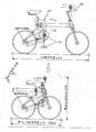
- FIG. 1 is a view showing an expanded state and a reduced state of the portable bicycle of the present invention.
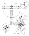
- Figure 2 is a view showing in detail the handlebar folding apparatus applied to the portable bicycle of the present invention.
- Figure 3 is a reference diagram showing the handlebar folding apparatus of the portable bicycle of the present invention.
- Figure 4 is a view showing a pedal crank arm separating apparatus applied to the portable bicycle of the present invention.
- FIG. 5 is a reference diagram showing a pedal crank arm separating apparatus of the portable bicycle of the present invention.
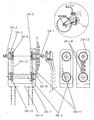
- Figure 6 is a view showing a separate drive shaft device of the portable bicycle of the present invention.
- FIG. 7 is a view showing a vehicle body length control device applied to the portable bicycle of the present invention.
- handlebar folding device 10-1 one side handlebar
- 40 body length control device 40-1: sliding block
- FIG. 2 a detailed configuration of the handlebar folding device 10 is illustrated.
- bicycles have a steering wheel that adjusts the direction of the bicycle by fixing the middle of the handlebar, which is a single circular tube, with a clamp attached to the tip of the stem connecting the fork and the handlebar, and forming handles (grip) on the left and right sides. Consists of.
- the steering handle bar is divided into one side handle bar (10-1) and the other handle bar (10-2) by a circular tube and the end of the tube of the one handle bar (10-1) and the other handle bar (10-2) Insert one side gear 10-3 and the other side gear 10-4 into the tube and fix them.
- a plurality of holes are formed in the upper surface of the lower part target bracket 10-5 supporting the steering wheel, and into the holes (not shown) on one side gear pin 10-6 and the other side gear pin 10-7.
- the one side gear 10-3 and the other side gear 10-4 are fixed thereto.
- the one side idle gear 10-8 and the other side idle gear 10-9 also have one side idle gear pin 10-10 and the other side idle gear pin 10-11 on the upper surface of the lower part target target 10-5. It is rotatably fixed to the hole.
- one side gear 10-3 and one side idle gear 10-8 are meshed with each other, and one side gear 10-3 is meshed with the other side idle gear 10-9 again in association with the other side idle gear.
- 10-9 is a structure in which a gear train engaged with the other gear 10-4 is formed.
- a hole (not shown) is formed in the center of the lower bracket 10-5 so that the center pin 10-12 penetrates and is inserted therein, and the spring 10-is formed on the outer circumference of the center pin 10-12. 13) is fitted. Since the spring 10-13 is fixed with a washer and a snap ring, the bottom surface of the lower bracket 10-5 is fixedly attached with a stem tube. Therefore, in the finished assembly, the through hole, the spring, the washer, and the snap ring are Invisible
- Two holes are machined at the same circumferential distance at an angle of 90 degrees with respect to the center of the fixing pin, respectively, on the upper surfaces of the one side gear 10-3 and the other side gear 10-4.
- the center pin 10-12, one gear fixing pin 10-14 and the other gear fixing pin 10-15 are placed in a straight line.
- the upper cover (10-16) formed with a hole through which the one side gear fixing pin (10-14), the other gear fixing pin (10-15) and the center pin (10-12) is assembled with a fastening bolt.
- FIG. 3 is a reference diagram for better understanding of the steering wheel bar folding apparatus 10.
- the two holes in the upper surface of the one side gear (10-3) and the other side gear (10-4) are each machined at a right angle to the center line of the handle bar at the same circumference at a 90 degree angle relative to the center of the fixed pin.
- the one side gear fixing pin 10-14 and the other side gear fixing pin 10-15 are inserted into the hole to fix the one side handle bar 10-1 and the other side handle bar 10-2.
- the driver's operation is the same when the one side and the other handle bar are to be unfolded on the same line for steering while driving the bicycle.
- FIG. 4 the pedal crank arm separating apparatus 20 is illustrated.
- Grooves are formed on the outer shape of the circular leading end of the pedal crank arm 20-1 to rotate the pedals of the bicycle to the appropriate torque, and the leaf springs 20-2 having holes formed at both ends of the pedal crank arm 20-1. Is inserted.
- the hole of one end of the leaf spring 20-2 is fixed to the groove of the pedal crank arm 20-1 with a fixing screw 20-3, and an upper end of the stop pin 20-4 is inserted into the other hole. Is fixed.
- One end of the stop pin 20-4 is inserted into a hole formed in the circular end of the pedal crank arm 20-1, and a part of the tip of the stop pin 20-4 is inserted into the leaf spring 20-20. It protrudes outside of 2), and the bent pull handle 20-5 for safety is rotatably fixed to this protrusion.
- the inner end of the drive shaft of the bicycle and the circular end of the pedal crank arm 20-1 are generally machined in the form of a square key and a square key groove, which are assembled and screwed together. do.
- the pedal crank arm 20-1 is inserted into the square key at the tip of the drive shaft, and then the pull handle 20-5 is released to the square key at the tip of the bicycle drive shaft with the restoring force of the leaf spring 20-2.
- a portion of the stop pin 20-4 is inserted into the hole.
- the pedal crank arm 20-1 is easily detached from and attached to the bicycle drive shaft by pulling or releasing the pull handle 20-5.
- the pedal crank arm which is not shown in the drawing, is stored under the saddle of the bicycle. You can.
- FIG. 5 is a reference diagram for better understanding of the pedal crank arm separating apparatus 20.
- the front end of the rotating shaft of the pedal 20-6 is formed in the form of a square key, and then the hole is formed to insert the stop pin, and then the groove is formed outside the lower circular part of the pedal crank arm into which the pedal is inserted.
- the spring, fixing screw, and stopper pins allow the pedal to be attached and detached separately.
- the chain sprocket is fixedly fixed to the drive shaft, the pedal crank arm is connected, and the pedal is pressed to advance the bicycle.
- the present invention is configured so that the front wheel of the bicycle can be inserted between the separated drive shaft after separating the drive shaft into two left and right to sufficiently reduce the length of the bicycle.
- the drive shaft is separated into one side drive shaft 30-1 and the other side drive shaft 30-2, and one side chain sprocket 30-5 is fixedly fixed to the tip of the one side drive shaft 30-1 like a normal bicycle.
- the pedal crank arm 20-1 is coupled and the pedal 20-6 is fixed.
- the pedal crank arm 20-1 is coupled to the front end of the other driving shaft 30-2, and the pedal 20-6 is fixed.
- the support bearing 30-3 is fixed to the one side drive shaft 30-1 and the other side drive shaft 30-2, thereby enabling smooth rotation, and the support bearing 30-3 is a U-shaped bracket 30-4. The left and right of each is inserted and fixed.
- one end of the one side drive shaft (30-1) and the other side drive shaft (30-2) is fixed to one side chain sprocket (30-5) and the other side chain sprocket (30-6).
- Both ends of the driven shaft 30-7 are rotatably supported by the rotary bearing 30-8 inside the U-shaped bracket 30-4, and one driven sprocket 30 is supported on the driven shaft 30-7.
- -9) and other driven sprockets (30-10) are fixed.
- One side driven sprocket (30-9) and the other side driven sprocket (30-10) is a chain 30-11, the one side chain sprocket (30-5) and one side driven sprocket (30-9) is connected, the other side chain Sprocket 30-6 and the other driven sprocket 30-10 are connected, respectively.
- the protective cover (30-12) is attached to the sprocket to cover the inside of the U-shaped bracket (30-4) to be secure.
- the same function can be configured by replacing the chain sprocket with the gear 30-13 and using the idle gear 30-14 instead of the chain.
- This structure allows one side and the other driving shaft to advance the bicycle in the same direction of rotation as in a conventional bicycle, and can satisfy the reduction range of the bicycle length which is the purpose of the portable bicycle.
- the vehicle body length adjusting device 40 is illustrated.
- a hollow rectangular bar-shaped sliding block 40-1 is provided, and the lower surface of the sliding block 40-1 is bolted to and fixed to a triangular frame of the bicycle.
- the left and right sides of the sliding block 40-1 is fixed to the saddle support clamp 40-2 for fixing the bicycle saddle, the saddle support clamp 40-2 can adjust the saddle up and down height Do it.
- the inner cross section of the sliding block 40-1 has a square cross-section structure of ⁇ type, as shown in the drawing, and is fixed to the bearing housing member to help rotate the front wheel fork of the bicycle into the square cross section of the ⁇ type horizontal frame (40). -3) is inserted and fixed to be slidable.
- the groove is formed to be cut into one side of the sliding block 40-1, a portion of the spiral cam roller 40-4 excellent in pressure and lock is inserted into the cut groove is fixed.
- the handle 40-5 of the spiral cam roller 40-4 is rotated to press or clamp one side of the K-type horizontal frame.
- the spiral cam roller 40-4 is attached to the support bracket 40-6 attached to the upper and lower surfaces of the sliding block 40-1, and is formed on the outer circumferential surface of the spiral cam roller 40-4.
- An elastic body 40-7 such as rubber, polyurethane, or a polymer compound is coated to prevent slipping of the K-type horizontal frame 40-3.
- the driver first stops driving the bicycle, rotates the handle of the spiral cam roller 40-4, and then pulls the steering wheel of the bicycle toward the driver's body to reduce the length of the bicycle. After grasping the handle of the handlebar folding device, fold the steering wheel by rotating one handlebar toward the driver's body.
- the pedal crank arm 20-1 of the bicycle is removed and mounted under the saddle of the bicycle to minimize the length, height, and volume of the bicycle. Hold the steering wheel of the car and roll or lift the wheels of the bike to carry and carry.
- the method of adjusting the height of the steering wheel of the bicycle is generally fixed and released by a clamp by inserting a circular tube attached to the steering wheel into a circular tube vertically connected from the fork of the front wheel of the bicycle, as in most bicycles. Same as known technology.
- the device 30 and the body length adjusting device 40 are not limited to the use that can be carried out only on a portable bicycle, and the technical scope of the present invention can be applied to general bicycles, as well as to the range of various devices that can be variously implemented. It will be said to have a spirit.
Abstract
The present invention concerns a portable bicycle, which is clearly differentiated from mini bicycles, portable bicycles or folding bicycles in general. It is of such a size that an adult can ride it without inconvenience, and is equipped with a bicycle handlebar folding apparatus (10) for convenience when parking in small spaces and when transporting. The bicycle of the present invention is also equipped with pedal crank arm detachment apparatus (20) which reduces the volume occupied by the bicycle to less than the width of the saddle, a detached drive shaft apparatus (30) which reduces the length of the bicycle and facilitate carrying and transporting, and an apparatus which adjusts length of frame (40). The portable bicycle of the present invention is a very useful invention that provides a method of decreasing or increasing the length and volume of the bicycle in order to facilitate carrying, storing and transporting in public transport such as buses and subway trains, by minimising the size of the bicycle.
Description
본 발명은 휴대용 자전거에 관한 것으로서, 더욱 상세하게는 자전거를 편리하게 운반과 보관을 할 수 있도록 자전거의 조향핸들 중간 지점에 소형의 기어트레인을 형성시켜 조향핸들을 반으로 접을 수 있도록 하여 그 폭을 줄이고, 자전거의 페달크랭크를 판스프링 또는 코일스프링의 탄성력으로 체결핀을 들어 올리거나 내릴 수 있도록 구성하여 페달크랭크를 분리시켜 자전거의 폭을 자전거 안장폭 이하로 더욱 줄일 수 있도록 하며, 자전거의 전체 길이를 줄일 수 있도록 가이드슬라이딩튜브와 자전거 구동축을 두 개로 분리 후 재연결시켜 자전거의 길이를 최소로 줄일 수 있게 한 휴대용 자전거에 관한 것이다.The present invention relates to a portable bicycle, and more particularly, to form a small geartrain at the midpoint of the steering wheel of the bicycle so that the bicycle can be conveniently transported and stored so that the steering wheel can be folded in half. The pedal crank of the bicycle can be lifted or lowered by the elastic force of the leaf spring or the coil spring so that the pedal crank can be separated to further reduce the width of the bicycle to less than the saddle width of the bicycle. The present invention relates to a portable bicycle that can reduce the length of the bicycle to a minimum by separating and reconnecting the guide sliding tube and the bicycle driving shaft in two so as to reduce the weight.
자전거는 현대 생활에서 건강을 위한 운동기구의 역할뿐만 아니라 근거리 이동수단으로 유용한 도구이다. 하지만 현대의 도로 사정상 자전거를 타기 위해서는 자전거를 안전하게 탈 수 있는 자전거 전용도로로 이동하거나 공원으로 나가서 타는 것이 일반적이다.The bicycle is a useful tool not only as a fitness device for modern life, but also as a short distance vehicle. However, in order to ride a bicycle due to modern road conditions, it is common to move to a bicycle path for safely riding a bicycle or to go out into a park.
하지만 자전거를 이동시키기 위해서는 자동차의 트렁크에 싣고 가거나 대중교통을 이용하여 들고 가야 하지만, 현실적으로 불가능하다.But in order to move a bicycle, you have to carry it in the trunk of a car or carry it by public transportation, but it is not practical.
이를 위하여 자전거를 접어서 부피를 줄여 트렁크에 집어 넣거나, 자전거의 바퀴를 작게 하여 부피를 줄인 자전거가 제작되었다.To this end, the bicycle was folded to reduce its volume and put it in the trunk, or to make the bicycle smaller and smaller.
이와 같이 바퀴의 직경을 작게하거나 자전거 차체의 크기만을 줄인 경우, 자전거 운전 중 작은 돌출물에서도 운전자는 그 충격의 정도가 크고 이동 속도가 느리며 작은 크기에서 운전의 불편을 느낀다.As such, when the diameter of the wheel is reduced or the size of the bicycle body is reduced only, the driver feels the inconvenience of driving at a small size even when the small protrusions while driving the bicycle have a large degree of impact and a slow moving speed.
또한 힌지핀을 부착하여 자전거의 길이를 반으로 접을 수 있도록 한 폴딩형 자전거는 반으로 접은 후의 부피가 매우 커지고, 자전거의 바퀴를 굴려서 이동시킬 수 없어 이동시 들어서 움직여야 하는 불편함이 있다. 따라서 수월하게 대중교통을 이용하여 자전거를 이동하기가 어려운 문제점이 있다.In addition, the folding type bike that can be folded in half by attaching a hinge pin is very inconvenient after folding in half, and there is an inconvenience of moving by moving the wheel of the bicycle because it can not be moved. Therefore, there is a problem that it is difficult to move the bicycle using public transportation easily.
본 발명은 전술한 바와 같은 문제를 해결하기 위하여 안출한 것으로서, 자전거의 길이와 폭을 줄인 후 자전거 손잡이를 잡고 자전거 바퀴를 굴리며 편리하게 이동할 수 있고, 손쉽게 들어 움직일 수 있도록 구성하며, 또한 그 크기와 부피에 있어 대중교통을 이용하여 이동할 경우에도 타인에게 불편함이 없도록 자전거 핸들을 반으로 접을 수 있고, 페달 크랭크 역시 손쉽게 분리될 수 있게 구성하며, 자전거의 크기와 그 길이에서도 일반 성인이 불편함 없이 운전을 가능하게 한 차체 크기로 구성함에도, 휴대 이동시 그 길이를 현저하게 줄일 수 있어 사용자가 진정으로 편리하게 사용할 수 있는 휴대용 자전거를 제공하고자 하는 목적이 있다.The present invention has been made to solve the problems as described above, and after reducing the length and width of the bicycle, holding the handle of the bicycle, and can be conveniently moved by rolling the bicycle wheel, it is configured to be easily lifted, and the size and In terms of volume, the handlebars can be folded in half so that others do not feel uncomfortable even when traveling by public transport, and the pedal cranks can be easily detached. Even if the body size is configured to allow driving, the length of the portable movement can be remarkably reduced, so that a user can use the portable bicycle in real convenience.
본 발명은 앞바퀴와 뒷바퀴 사이의 간격을 근접하게 줄일 수 있게 수평프레임과 차체길이조절장치를 구성하여 바퀴를 굴려 이동할 수 있게 한다.The present invention is to configure the horizontal frame and the body length adjustment device to reduce the distance between the front wheel and the rear wheel to be able to roll the wheel to move.
본 발명은 전술한 목적을 달성하기 위하여 자전거를 휴대하여 이동 및 보관을 할 수 있는 휴대용 자전거에 있어서, 일측핸들바(10-1)와 타측핸들바(10-2)의 마주보는 단부가 서로 연결되어 맞물리는 일측기어(10-3)와 타측기어(10-4)에 의해 회동가능하게 고정되고, 손잡이(10-17)에 의해 일측기어(10-3)와 타측기어(10-4)의 운동이 제한되는 핸들바접이장치(10); 페달크랭크암(20-1)의 양단에 각각 사각키홈이 형성되어 페달(20-6)과 구동축의 사각키와 결합되고, 멈춤핀(20-4)이 판스프링(20-2)에 의해 탄력지지되면서 페달(20-6)과 구동축의 사각키를 탈착 가능하게 고정하는 페달크랭크암분리장치(20); 두개의 페달크랭크암(20-1)과 연결되는 일측구동축(30-1)과 타측구동축(30-2)이 분리되어 형성되고, 일측구동축(30-1)과 타측구동축(30-2)은 U형브라켓(30-4)에 고정되는 피동구동축(30-7)과 동력전달되도록 연결되며, 크기를 줄일때 U형브라켓(30-4)의 내부로 앞바퀴가 삽입되도록 형성되는 분리된구동축장치(30); 앞바퀴의 포크에 고정되는 ㅁ형수평프레임(40-3)이 내부에서 슬라이딩되도록 슬라이딩블록(40-1)이 구비되고, 슬라이딩블록(40-1)에 높이 조절 가능하게 안장이 고정되며, 슬라이딩블록(40-1)의 일측에 고정된 스파이럴캠로울러(40-4)에 의하여 ㅁ형수평프레임(40-3)의 고정과 이동이 가능한 차체길이조절장치(40);로 구성되는 것을 특징으로 하며, 핸들바접이장치(10)는 일측핸들바(10-1)와 타측핸들바(10-2)의 양단에 일측기어(10-3)와 타측기어(10-4)가 일측기어핀(10-6)과 타측기어핀(10-7)으로 하부브라켓(10-5)에 고정되고, 일측기어(10-3)와 타측기어(10-4) 사이에 일측아이들기어(10-8)와 타측아이들기어(10-9)가 일측아이들기어핀(10-10)과 타측아이들기어핀(10-11)으로 서로 맞물리게 고정되며, 하부브라켓(10-5) 중앙에 홀이 형성되어 중앙핀(10-12)이 관통되어 삽입되고, 관통된 중앙핀(10-12)의 외주로 스프링(10-13)이 끼워져 와셔 스냅링으로 고정되며, 일측기어(10-3) 및 타측기어(10-4)의 상면으로 2개의 구멍이 각각 고정핀 중심선을 기준으로 90도 각도로 동일 원주거리에 형성되고, 상기 구멍 속으로 일측기어고정핀(10-14)과 타측기어고정핀(10-15)이 삽입되어 위치 고정되고, 중앙핀(10-12)과 일측기어고정핀(10-14)과 타측기어고정핀(10-15)의 상단이 상부커버(10-16)에 형성된 구멍을 통하여 손잡이(10-17) 저면에 가공된 3개의 구멍에 고정되며, 페달크랭크암분리장치(20)는 페달크랭크암(20-1)의 원형 단부 내경에 형성된 사각키홈 일측에 핀홀이 형성되어 멈춤핀(20-4)이 삽입되고, 원형 단부 외경에 요홈이 형성되어 판스프링(20-2)의 일단이 고정나사(20-3)로 고정되고, 판스프링(20-2)의 타단에 멈춤핀(20-4)이 고정되어 탄력지지되며, 멈춤핀(20-4)의 선단 일부가 상기 판스프링(20-2)의 외부로 돌출되어 당김손잡이(20-5)가 회동가능하게 고정되고, 멈춤핀(20-4)이 페달이나 구동축의 사각키홈에 형성된 홀에 삽입되거나 이탈되면서 고정과 분리가 가능하며, 분리된구동축장치(30)는 일측구동축(30-1)과 타측구동축(30-2)으로 분리되어 형성되고, 일측구동축(30-1)과 타측구동축(30-2)의 선단에는 일측체인스프로켓(30-5)과 타측체인스프로켓(30-6)이 축설 고정되며, 일측구동축(30-1)과 타측구동축(30-2)에 고정된 지지베어링(30-3)이 U형브라켓(30-4)의 좌,우에 각각 삽입되어 고정되고, U형브라켓(30-4)의 내측에서 양단이 회전베어링(30-8)으로 회전가능하게 지지된 피동구동축(30-7)에 일측피동스프로켓(30-9)과 타측피동스프로켓(30-10) 축설 고정되며, 체인(30-11)으로 일측체인스프로켓(30-5)과 일측피동스프로켓(30-9)이 연결되고, 타측체인스프로켓(30-6)과 타측피동스프로켓(30-10)이 각각 연결되며, 차체길이 조절장치(40)는 슬라이딩블록(40-1)이 구비되어 자전거의 삼각프레임에 고정되고, 슬라이딩블록(40-1)의 좌,우 측면에 안장지지클램프(40-2)가 고정되며, 슬라이딩블록(40-1)의 내부 단면인 ㅁ형의 사각 단면 안으로 베어링하우징 부재에 부착 고정된 ㅁ형수평프레임(40-3)이 슬라이딩되어 고정되고, 슬라이딩블록(40-1)의 일측면에 요홈이 절개되어 형성되며, 절개된 요홈에 스파이럴캠로울러(40-4)의 일부가 삽입되어 고정되고, 스파이럴캠로울러(40-4)의 손잡이(40-5)를 회전시켜 ㅁ형수평프레임의 일측면을 가압하여 클램핑하거나 해제시키며, 스파이럴캠로울러(40-4)의 외주면에는 고무, 폴리우레탄, 고분자화합물 등의 탄성체(40-7)가 코팅되어 ㅁ형수평프레임(40-3)의 미끄러짐이 방지되는 것을 특징으로 하는 휴대용 자전거를 제공한다.The present invention is a portable bicycle that can be moved and stored by carrying a bicycle in order to achieve the above object, the opposite ends of one handle bar (10-1) and the other handle bar (10-2) are connected to each other Of the one-side gear 10-3 and the other-side gear 10-4 by the handle 10-17. Handle bar folding device 10 is limited to movement; Square key grooves are formed at both ends of the pedal crank arm 20-1, respectively, and are engaged with the square key of the pedal 20-6 and the drive shaft, and the stop pin 20-4 is elastic by the leaf spring 20-2. Pedal crank arm separation device 20 for supporting the pedal 20-6 and the square key of the drive shaft detachably; One side driving shaft 30-1 and the other side driving shaft 30-2 which are connected to two pedal crank arms 20-1 are formed separately, and the one side driving shaft 30-1 and the other side driving shaft 30-2 are formed. Separated drive shaft device is connected to the power drive shaft (30-7) is fixed to the U-shaped bracket (30-4) and is formed so that the front wheel is inserted into the U-shaped bracket (30-4) when reducing the size 30; Sliding block (40-1) is provided so that the horizontal horizontal frame (40-3) is fixed to the fork of the front wheel sliding inside, the saddle is fixed to the sliding block (40-1) adjustable height, sliding block ( 40-1) by the spiral cam roller (40-4) is fixed to one side of the body length adjusting device 40 which can be fixed and movable ㅁ -type horizontal frame (40-3); The bar foldable device 10 has one gear 10-3 and the other gear 10-4 at both ends of one handle bar 10-1 and the other handle bar 10-2, and one gear pin 10-6. ) And the other gear pin (10-7) is fixed to the lower bracket (10-5), between one side gear (10-3) and the other gear (10-4) one side gear gear (10-8) and the other side children The gear 10-9 is fixedly engaged with one side idle gear pin 10-10 and the other idle gear pin 10-11, and a hole is formed in the center of the lower bracket 10-5 to form a center pin 10-10. 12) is inserted through, Spring 10-13 is inserted into the outer circumference of the center pin 10-12, and is fixed by the washer snap ring, and two holes are fixed to the upper surfaces of the one gear 10-3 and the other gear 10-4, respectively. It is formed at the same circumferential distance at an angle of 90 degrees with respect to the center line, and the one side gear fixing pin (10-14) and the other gear fixing pin (10-15) is inserted into the hole to fix the position, the center pin (10- 12) and three holes processed on the bottom of the handle (10-17) through the hole formed in the upper cover (10-16) the upper end of the one side gear fixing pin (10-14) and the other gear fixing pin (10-15) Fixed to the pedal crank arm separation device 20 has a pinhole formed at one side of a square keyway formed at an inner diameter of a circular end of the pedal crank arm 20-1 so that the stop pin 20-4 is inserted into the outer diameter of the circular end. The groove is formed so that one end of the leaf spring (20-2) is fixed by a fixing screw (20-3), the stop pin (20-4) is fixed to the other end of the leaf spring (20-2) is elastically supported, stop Pin (2 A portion of the tip of 0-4 is protruded to the outside of the leaf spring 20-2 so that the pull handle 20-5 is rotatably fixed, and the stop pin 20-4 is mounted on the square keyway of the pedal or drive shaft. It can be fixed and separated by being inserted into or away from the formed hole, and the separated driving shaft device 30 is formed by being separated into one side driving shaft 30-1 and the other side driving shaft 30-2, and one side driving shaft 30-1. One side chain sprocket 30-5 and the other side chain sprocket 30-6 are fixedly fixed to the front end of the other side drive shaft 30-2, and fixed to one side drive shaft 30-1 and the other side drive shaft 30-2. Supported bearings 30-3 are inserted and fixed to the left and right sides of the U-shaped bracket 30-4, respectively, and both ends of the U-shaped bracket 30-4 are rotatable by the rotary bearings 30-8. One driven sprocket 30-9 and the other driven sprocket 30-10 are fixedly secured to the driven drive shaft 30-7, and the one side chain sprocket 30-5 and one driven with chain 30-11. Sprocket (30-9) The other side chain sprocket 30-6 and the other driven sprocket 30-10 are connected to each other, and the body length adjusting device 40 is provided with a sliding block 40-1 and fixed to a triangular frame of the bicycle. , The saddle support clamp 40-2 is fixed to the left and right sides of the sliding block 40-1, and is fixed to the bearing housing member in the square section of the K-type, which is an inner cross-section of the sliding block 40-1. The horizontal frame 40-3 is fixed by sliding, the groove is formed on one side of the sliding block 40-1 is formed, the part of the spiral cam roller (40-4) is inserted and fixed to the cut groove By rotating the handle 40-5 of the spiral cam roller 40-4, one side of the horizontal frame is pressed and clamped or released. The outer surface of the spiral cam roller 40-4 has rubber, polyurethane, and polymer. An elastic body 40-7 such as a compound is coated to slide the K-type horizontal frame 40-3. It provides a portable bicycle characterized in that the protection.
도 1은 본 발명의 휴대용 자전거의 펼쳐진 상태와 부피를 축소한 상태를 도시한 도면.1 is a view showing an expanded state and a reduced state of the portable bicycle of the present invention.
도 2는 본 발명의 휴대용 자전거에 적용된 핸들바접이장치를 상세히 도시한 도면.Figure 2 is a view showing in detail the handlebar folding apparatus applied to the portable bicycle of the present invention.
도 3은 본 발명의 휴대용 자전거의 핸들바접이장치를 도시한 참고도.Figure 3 is a reference diagram showing the handlebar folding apparatus of the portable bicycle of the present invention.
도 4는 본 발명의 휴대용 자전거에 적용된 페달크랭크암분리장치를 도시한 도면.Figure 4 is a view showing a pedal crank arm separating apparatus applied to the portable bicycle of the present invention.
도 5는 본 발명의 휴대용 자전거의 페달크랭크암분리장치를 도시한 참고도.5 is a reference diagram showing a pedal crank arm separating apparatus of the portable bicycle of the present invention.
도 6은 본 발명의 휴대용 자전거의 분리된구동축장치를 도시한 도면.Figure 6 is a view showing a separate drive shaft device of the portable bicycle of the present invention.
도 7은 본 발명의 휴대용 자전거에 적용된 차체길이 조절장치를 도시한 도면.7 is a view showing a vehicle body length control device applied to the portable bicycle of the present invention.
< 도면의 주요 부분에 대한 부호의 간단한 설명 > <Brief description of symbols for the main parts of the drawings>
10 : 핸들바접이장치 10-1 : 일측핸들바10: handlebar folding device 10-1: one side handlebar
10-2 : 타측핸들바 10-3 : 일측기어10-2: other handle bar 10-3: one gear
10-4 : 타측기어 10-5 : 하부브라켓10-4: other gear 10-5: lower bracket
10-6 : 일측기어핀 10-7 : 타측기어핀10-6: One side gear pin 10-7: The other side gear pin
10-8 : 일측아이들기어 10-9 : 타측아이들기어10-8: One side children gear 10-9: The other side children gear
10-10 : 일측아이들기어핀 10-11 : 타측아이들기어핀10-10: One side idle gear pin 10-11: The other side idle gear pin
10-12 : 중앙핀 10-13 : 스프링10-12: Center Pin 10-13: Spring
10-14 : 일측기어고정핀 10-15 : 타측기어고정핀10-14: One side gear fixing pin 10-15: The other side gear fixing pin
10-16 : 상부커버 10-17 : 손잡이10-16: Top cover 10-17: Handle
20 : 페달크랭크암분리장치 20-1 : 페달크랭크암20: Pedal Crank Arm Separator 20-1: Pedal Crank Arm
20-2 : 판스프링 20-3 : 고정나사20-2: Leaf spring 20-3: Fixing screw
20-4 : 멈춤핀 20-5 : 당김손잡이20-4: Stop pin 20-5: Pull handle
20-6 : 페달 30 : 분리된구동축장치20-6: Pedal 30: Separate Drive Shaft
30-1 : 일측구동축 30-2 : 타측구동축30-1: one side drive shaft 30-2: other side drive shaft
30-3 : 지지베어링 30-4 : U형브라켓30-3: Support bearing 30-4: U type bracket
30-5 : 일측체인스프로켓 30-6 : 타측체인스프로켓30-5: One side chain sprocket 30-6: The other side chain sprocket
30-7 : 피동구동축 30-8 : 회전베어링30-7: Driven shaft 30-8: Rotating bearing
30-9 : 일측피동스프로켓 30-10 : 타측피동스프로켓30-9: One side driven sprocket 30-10: Other side driven sprocket
30-11 : 체인 30-12 : 보호커버30-11: chain 30-12: protective cover
30-13 : 기어 30-14 : 아이들기어30-13: Gear 30-14: Children Gears
40 : 차체길이조절장치 40-1 : 슬라이딩블록40: body length control device 40-1: sliding block
40-2 : 안장지지클램프 40-3 : ㅁ형수평프레임40-2: Saddle Support Clamp 40-3: WH Horizontal Frame
40-4 : 스파이럴캠로울러 40-5 : 손잡이40-4: Spiral Cam Roller 40-5: Handle
40-6 : 지지브라켓 40-7 : 탄성체40-6: support bracket 40-7: elastic body
이하 첨부된 도면을 참조하여 본 발명의 구성을 상세히 설명하면 다음과 같다.Hereinafter, the configuration of the present invention will be described in detail with reference to the accompanying drawings.
첨부한 도 1에는 전개된 자전거와, 신축되어진 자전거가 도시되고, 자전거를 휴대와 이동이 편리하도록 한 핸들바접이장치(10), 페달크랭크암분리장치(20), 분리된구동축장치(30), 차체길이 조절장치(40)가 형성된 위치가 도시되어 있다.1 is shown a deployed bicycle, and a stretched bicycle, the handlebar folding device 10, the pedal crank arm separating device 20, the separate driving shaft device 30 to make the bicycle easy to carry and move. , The position where the body length adjusting device 40 is formed is shown.
첨부한 도 2에서는 핸들바접이장치(10)의 상세한 구성이 도시되어 있다.In FIG. 2, a detailed configuration of the handlebar folding device 10 is illustrated.
통상 자전거는 포오크와 핸들바를 연결하는 스템의 선단에 부착된 클램프로 한 개의 원형 튜브인 핸들바 중간을 고정시키고, 좌,우에 손잡이부(글립)를 형성시켜 자전거의 방향을 조정하는 자전거 조향핸들바가 구성되어 있다.In general, bicycles have a steering wheel that adjusts the direction of the bicycle by fixing the middle of the handlebar, which is a single circular tube, with a clamp attached to the tip of the stem connecting the fork and the handlebar, and forming handles (grip) on the left and right sides. Consists of.
이러한 조향핸들바를 본 발명에서는 원형튜브로 일측핸들바(10-1)와 타측핸들바(10-2)로 나누고 상기 일측핸들바(10-1) 및 타측핸들바(10-2)의 튜브 선단에 일측기어(10-3)와 타측기어(10-4)를 튜브 속으로 삽입 후 고정시킨다.In the present invention, the steering handle bar is divided into one side handle bar (10-1) and the other handle bar (10-2) by a circular tube and the end of the tube of the one handle bar (10-1) and the other handle bar (10-2) Insert one side gear 10-3 and the other side gear 10-4 into the tube and fix them.
조향핸들바를 지지하는 하부부라겟(10-5)의 상면에 다수개의 구멍이 형성되고, 이 구멍 속으로(도면 미도시) 일측기어핀(10-6)과 타측기어핀(10-7)에 의하여 상기 일측기어(10-3) 및 타측기어(10-4)가 고정된다.A plurality of holes are formed in the upper surface of the lower part target bracket 10-5 supporting the steering wheel, and into the holes (not shown) on one side gear pin 10-6 and the other side gear pin 10-7. The one side gear 10-3 and the other side gear 10-4 are fixed thereto.
일측아이들기어(10-8)와 타측아이들기어(10-9) 역시 일측아이들기어핀(10-10)과 타측아이들기어핀(10-11)으로 상기의 하부부라겟(10-5) 상면의 구멍에 회전가능하게 고정된다.The one side idle gear 10-8 and the other side idle gear 10-9 also have one side idle gear pin 10-10 and the other side idle gear pin 10-11 on the upper surface of the lower part target target 10-5. It is rotatably fixed to the hole.
여기서, 일측기어(10-3)와 일측아이들기어(10-8)는 치합되어지고, 일측기어(10-3)는 연계하여 다시 타측아이들기어(10-9)와도 치합 되어지며, 타측아이들기어(10-9)는 타측기어(10-4)와 치합되어진 기어트레인이 형성된 구조이다.Here, one side gear 10-3 and one side idle gear 10-8 are meshed with each other, and one side gear 10-3 is meshed with the other side idle gear 10-9 again in association with the other side idle gear. 10-9 is a structure in which a gear train engaged with the other gear 10-4 is formed.
이는 컴펙트한 구성과 상기 일측 및 타측기어의 회전 방향이 서로 반대가 되도록 하기 위한 구조이다.This is a structure for making a compact configuration and the rotation direction of the one side and the other gear to be opposite to each other.
그리고, 상기 하부브라켓(10-5) 중앙에 홀(도면 미도시)이 형성되어 중앙핀(10-12)이 관통되어 삽입되고, 관통된 중앙핀(10-12)의 외주로 스프링(10-13)이 끼워진다. 스프링(10-13)은 와셔, 스냅링으로 고정된 후 상기 하부브라켓(10-5) 저면은 스템튜브와 고정 부착되므로 완성 조립품에서는 상기 중앙핀(10-12) 관통 부위와 스프링, 와셔, 스냅링은 보이지 않게 된다.In addition, a hole (not shown) is formed in the center of the lower bracket 10-5 so that the center pin 10-12 penetrates and is inserted therein, and the spring 10-is formed on the outer circumference of the center pin 10-12. 13) is fitted. Since the spring 10-13 is fixed with a washer and a snap ring, the bottom surface of the lower bracket 10-5 is fixedly attached with a stem tube. Therefore, in the finished assembly, the through hole, the spring, the washer, and the snap ring are Invisible
상기 일측기어(10-3) 및 타측기어(10-4)의 상면으로 2개의 구멍이 각각 고정핀 중심선을 기준으로 90도 각도로 동일 원주거리에 가공된다.Two holes are machined at the same circumferential distance at an angle of 90 degrees with respect to the center of the fixing pin, respectively, on the upper surfaces of the one side gear 10-3 and the other side gear 10-4.
상기 일측핸들바(10-1)와 타측핸들바(10-2)가 일 직선상일 때 상기 중앙핀(10-12)과 좌.우로 나란히 가공된 구멍 속으로 일측기어고정핀(10-14)과 타측기어고정핀(10-15)이 삽입이 된다.When the one handle bar (10-1) and the other handle bar (10-2) is in a straight line, the one side gear fixing pin (10-14) into the hole processed in parallel with the center pin (10-12) left and right. And the other gear fixing pin (10-15) is inserted.
따라서 상기 중앙핀(10-12)과 일측기어고정핀(10-14)과 타측기어고정핀(10-15)은 일직선상으로 놓여지게 된다. 그리고 일측기어고정핀(10-14)과 타측기어고정핀(10-15)과 중앙핀(10-12)이 관통되는 구멍이 형성된 상부커버(10-16)가 체결볼트로 조립된다.Therefore, the center pin 10-12, one gear fixing pin 10-14 and the other gear fixing pin 10-15 are placed in a straight line. And the upper cover (10-16) formed with a hole through which the one side gear fixing pin (10-14), the other gear fixing pin (10-15) and the center pin (10-12) is assembled with a fastening bolt.
상기의 상부커버(10-16)에 관통된 3개의 구멍으로 상기 중앙핀(10-12)과 일측기어고정핀(10-14)과 타측기어고정핀(10-15)의 선단이 돌출되고, 손잡이(10-17) 하면에 가공된 3개의 구멍(도면 미도시) 속으로 상기 중앙핀(10-12)과 일측기어고정핀(10-14)과 타측기어고정핀(10-15)의 선단이 삽입되어 고정된다.The front end of the center pin (10-12), the one side gear fixing pin (10-14) and the other gear fixing pin (10-15) protrudes into three holes penetrated through the upper cover (10-16), The tip of the center pin (10-12), one side gear fixing pin (10-14) and the other side of the gear fixing pin (10-15) into three holes (not shown) processed in the lower surface of the handle (10-17) It is inserted and fixed.
도 3는 상기 조향핸들바접이장치(10)의 이해를 돕기 위한 참고도이다.3 is a reference diagram for better understanding of the steering wheel bar folding apparatus 10.
이에, 동작 관계를 설명하면 먼저 손잡이(10-17)를 잡고 수직으로 들어올리면, 스프링(10-13)이 압축되고, 상기 중앙핀(10-12)과 일측기어고정핀(10-14)과 타측기어고정핀(10-15)이 손잡이(10-17)와 같이 수직으로 들어 올려진다. 이때 일측핸들바(10-1) 및 타측핸들바(10-2) 중에서 한쪽을 잡고 자전거 운전자의 몸쪽으로 회전시키면 반대편의 핸들바도 따라서 몸쪽으로 회전되어 지고, 잡았던 손잡이(10-17)를 놓으면 스프링(10-13)의 반력으로 상기 손잡이(10-17)와 손잡이(10-17)에 고정된 중앙핀(10-12)과 일측기어고정핀(10-14)과 타측기어고정핀(10-15)이 따라서 내려간다.Thus, when explaining the operation relationship, first hold the handle (10-17) and lift it vertically, the spring (10-13) is compressed, the center pin (10-12) and the one-side gear fixing pin (10-14) and The other gear fixing pin 10-15 is lifted vertically like the handle 10-17. At this time, if one of the handlebar 10-1 and the other handlebar 10-2 is grabbed and rotated toward the body of the cyclist, the handlebar of the opposite side is also rotated toward the body, and when the handle 10-17 is released, the spring is released. Central pin 10-12 and one gear fixing pin 10-14 and the other gear fixing pin 10-17 fixed to the handle 10-17 and the handle 10-17 by reaction force of (10-13). 15) So go down.
이때, 상기의 일측기어(10-3) 및 타측기어(10-4)의 상면으로 2개의 구멍이 각각 고정핀 중심선을 기준으로 90도 각도로 동일 원주거리에 핸들바의 중심선과 직각으로 가공된 구멍속으로 일측기어고정핀(10-14)과 타측기어고정핀(10-15)이 삽입이 되어져 일측핸들바(10-1) 및 타측핸들바(10-2)를 고정시키게 된다.At this time, the two holes in the upper surface of the one side gear (10-3) and the other side gear (10-4) are each machined at a right angle to the center line of the handle bar at the same circumference at a 90 degree angle relative to the center of the fixed pin. The one side gear fixing pin 10-14 and the other side gear fixing pin 10-15 are inserted into the hole to fix the one side handle bar 10-1 and the other side handle bar 10-2.
또한 자전거 운전중 조향을 위해 상기 일측 및 타측핸들바를 동일 선상으로 펼치고자 하는 경우에도 운전자의 조작 동작은 같다.In addition, the driver's operation is the same when the one side and the other handle bar are to be unfolded on the same line for steering while driving the bicycle.
도 4에서는 페달크랭크암분리장치(20)가 도시되어 있다.In FIG. 4, the pedal crank arm separating apparatus 20 is illustrated.
자전거의 페달을 회전시켜 구동축을 적정 토오크로 회전시키기 위한 페달크랭크암(20-1)의 원형 선단부 외형에 요홈이 가공되어 형성되고, 그 요홈 안으로 양단에 각각 구멍이 형성된 판스프링(20-2)이 삽입된다.Grooves are formed on the outer shape of the circular leading end of the pedal crank arm 20-1 to rotate the pedals of the bicycle to the appropriate torque, and the leaf springs 20-2 having holes formed at both ends of the pedal crank arm 20-1. Is inserted.
상기 판스프링(20-2) 일단의 구멍은 고정나사(20-3)로 상기 페달크랭크암(20-1)의 요홈에 고정되고, 다른 한쪽 구멍에는 멈춤핀(20-4)의 상단이 삽입되어 고정된다. 상기 페달크랭크암(20-1)의 원형 선단부에 가공되어져 있는 구멍으로 상기 멈춤핀(20-4)의 일단이 삽입되고, 상기 멈춤핀(20-4)의 선단 일부가 상기 판스프링(20-2)의 외부로 돌출되며, 이러한 돌출부에는 안전을 위한 굽어진 형상의 당김손잡이(20-5)가 회동가능하게 고정된다.The hole of one end of the leaf spring 20-2 is fixed to the groove of the pedal crank arm 20-1 with a fixing screw 20-3, and an upper end of the stop pin 20-4 is inserted into the other hole. Is fixed. One end of the stop pin 20-4 is inserted into a hole formed in the circular end of the pedal crank arm 20-1, and a part of the tip of the stop pin 20-4 is inserted into the leaf spring 20-20. It protrudes outside of 2), and the bent pull handle 20-5 for safety is rotatably fixed to this protrusion.
*이러한 구조로 동작 관계를 설명하면, 확실한 동력 전달을 목적으로 통상 자전거의 구동축 선단과 페달크랭크암(20-1)의 원형 선단부의 내부는 사각키와 사각키홈 형태로 가공되어져 상호 조립되고 나사로 고정된다.* When explaining the operation relationship with such a structure, for the purpose of reliably transmitting power, the inner end of the drive shaft of the bicycle and the circular end of the pedal crank arm 20-1 are generally machined in the form of a square key and a square key groove, which are assembled and screwed together. do.
본 발명의 구조로 구동축 선단의 사각키에 상기 페달크랭크암(20-1)의 내부 사각키홈을 결합하고자 하는 경우, 굽어진 형상의 상기 당김손잡이(20-5)를 잡아 들어 올린 후, 당김손잡이(20-5)를 잡아당긴다. 따라서 당김손잡이(20-5)에 가해진 힘이 상기 판스프링(20-2)의 탄성을 극복하여 상기 멈춤핀(20-4)이 들어 올려진다.When the inner square key groove of the pedal crank arm 20-1 is coupled to the square key at the end of the drive shaft with the structure of the present invention, after pulling up the pull handle 20-5 having a curved shape, the pull handle Pull out (20-5). Therefore, the force applied to the pull handle 20-5 overcomes the elasticity of the leaf spring 20-2 so that the stop pin 20-4 is lifted up.
이때, 상기 페달크랭크암(20-1)을 구동축 선단의 사각키에 삽입시킨 후 상기 당김손잡이(20-5)를 놓아 판스프링(20-2)의 복원력으로 자전거 구동축 선단의 사각키에 가공된 구멍으로 상기 멈춤핀(20-4)의 일부가 삽입된다.At this time, the pedal crank arm 20-1 is inserted into the square key at the tip of the drive shaft, and then the pull handle 20-5 is released to the square key at the tip of the bicycle drive shaft with the restoring force of the leaf spring 20-2. A portion of the stop pin 20-4 is inserted into the hole.
이러한 멈춤핀(20-4)으로 인하여 자전거를 운전하는 중에도 자전거 구동축에서 상기 페달크랭크암(20-1)이 이탈되지 않는다.Due to the stop pin 20-4, the pedal crank arm 20-1 is not separated from the bicycle drive shaft even while driving the bicycle.
*상기 당김손잡이(20-5)를 잡아당기거나 놓음으로서 상기 페달크랭크암(20-1)이 자전거 구동축에서 손쉽게 탈, 부착되고, 탈착된 페달크랭크암은 도면에 도시하지는 않으나 자전거의 안장 밑에 보관시킬 수 있다.* The pedal crank arm 20-1 is easily detached from and attached to the bicycle drive shaft by pulling or releasing the pull handle 20-5. The pedal crank arm, which is not shown in the drawing, is stored under the saddle of the bicycle. You can.
도 5는 상기 페달크랭크암분리장치(20)의 이해를 돕기 위한 참고도이다.5 is a reference diagram for better understanding of the pedal crank arm separating apparatus 20.
자전거 페달에 있어서도 페달(20-6)의 회전축 선단을 사각키 형태로 제작 후, 멈춤핀이 삽입 되도록 구멍을 가공하고 이어서 페달이 삽입되는 상기 페달크랭크암의 하단 원형부 외부에 요홈을 가공하고 판스프링, 고정나사, 멈춤핀의 구성으로 페달만을 별도로 탈부착 가능하게 할 수 있다.In the bicycle pedal, the front end of the rotating shaft of the pedal 20-6 is formed in the form of a square key, and then the hole is formed to insert the stop pin, and then the groove is formed outside the lower circular part of the pedal crank arm into which the pedal is inserted. The spring, fixing screw, and stopper pins allow the pedal to be attached and detached separately.
도 6 에서는 분리된구동축장치(30)가 도시되어 있다.6 shows a separate drive shaft device 30.
통상의 자전거는 구동축에 체인스프로켓을 축설 고정하고 페달크랭크암을 연결 후 페달을 밟아 자전거를 전진 시킨다. 종래의 경우 본 발명의 요지와 같이 자전거의 앞바퀴를 운전자 쪽으로 잡아끌어 길이를 축소하고자 하는 경우, 자전거의 중앙에 고정 설치되어있는 구동축 부재의 간섭으로 원하는 길이로 축소할 수가 없다. 따라서 본 발명은 구동축을 좌.우 2개로 분리 후 분리된 구동축 사이로 자전거 앞바퀴가 삽입 가능하도록 하여 자전거의 길이를 충분하게 축소 가능하도록 구성한다.In a typical bicycle, the chain sprocket is fixedly fixed to the drive shaft, the pedal crank arm is connected, and the pedal is pressed to advance the bicycle. In the conventional case, when the front wheel of the bicycle is pulled toward the driver to reduce the length as in the gist of the present invention, it cannot be reduced to the desired length due to the interference of the drive shaft member fixed to the center of the bicycle. Therefore, the present invention is configured so that the front wheel of the bicycle can be inserted between the separated drive shaft after separating the drive shaft into two left and right to sufficiently reduce the length of the bicycle.
먼저 구동축을 일측구동축(30-1)과 타측구동축(30-2)으로 분리하고, 통상의 자전거와 같이 상기 일측구동축(30-1)의 선단에는 일측체인스프로켓(30-5)이 축설 고정되며, 이와 연계하여 페달크랭크암(20-1)이 결합되고 페달(20-6)이 고정된다.First, the drive shaft is separated into one side drive shaft 30-1 and the other side drive shaft 30-2, and one side chain sprocket 30-5 is fixedly fixed to the tip of the one side drive shaft 30-1 like a normal bicycle. In this connection, the pedal crank arm 20-1 is coupled and the pedal 20-6 is fixed.
상기 타측구동축(30-2)의 선단에도 페달크랭크암(20-1)이 결합되고, 페달(20-6)이 고정된다.The pedal crank arm 20-1 is coupled to the front end of the other driving shaft 30-2, and the pedal 20-6 is fixed.
상기 일측구동축(30-1)과 타측구동축(30-2)에 지지베어링(30-3)이 고정되어 원활한 회전이 가능하고, 상기 지지베어링(30-3)은 U형브라켓(30-4)의 좌,우에 각각 삽입되어 고정된다.The support bearing 30-3 is fixed to the one side drive shaft 30-1 and the other side drive shaft 30-2, thereby enabling smooth rotation, and the support bearing 30-3 is a U-shaped bracket 30-4. The left and right of each is inserted and fixed.
또한 상기 일측구동축(30-1)과 타측구동축(30-2)의 일단에는 일측체인스프로켓(30-5)과 타측체인스프로켓(30-6) 각각 축설 고정된다. 그리고 U형브라켓(30-4)의 내측에서 피동구동축(30-7)의 양단이 회전베어링(30-8)으로 회전가능하게 지지되고, 상기 피동구동축(30-7)에는 일측피동스프로켓(30-9)과 타측피동스프로켓(30-10) 축설 고정된다.In addition, one end of the one side drive shaft (30-1) and the other side drive shaft (30-2) is fixed to one side chain sprocket (30-5) and the other side chain sprocket (30-6). Both ends of the driven shaft 30-7 are rotatably supported by the rotary bearing 30-8 inside the U-shaped bracket 30-4, and one driven sprocket 30 is supported on the driven shaft 30-7. -9) and other driven sprockets (30-10) are fixed.
일측피동스프로켓(30-9)과 타측피동스프로켓(30-10)은 체인(30-11)으로 상기의 일측체인스프로켓(30-5)과 일측피동스프로켓(30-9)이 연결되고, 타측체인스프로켓(30-6)과 타측피동스프로켓(30-10)이 각각 연결된다.One side driven sprocket (30-9) and the other side driven sprocket (30-10) is a chain 30-11, the one side chain sprocket (30-5) and one side driven sprocket (30-9) is connected, the other side chain Sprocket 30-6 and the other driven sprocket 30-10 are connected, respectively.
그리고 U형브라켓(30-4)의 내측으로 스프로켓들을 가리도록 보호커버(30-12)가 부착되어 안전하게 한다.And the protective cover (30-12) is attached to the sprocket to cover the inside of the U-shaped bracket (30-4) to be secure.
여기서 통상의 지식으로 상기의 체인스프로켓을 대신하여 기어(30-13)로 대체하고 상기 체인을 대신하여 아이들기어(30-14)를 사용 하므로서 동일 기능이 나타나도록 구성 할 수 있다. 이러한 구조는 통상의 자전거에서와 같이 일측 및 타측구동축이 동일한 회전 방향을 지니고 자전거를 전진 시키며, 본 휴대용 자전거의 목적인 자전거 길이의 축소 범위를 충족 시킬수 있다.Here, in the conventional knowledge, the same function can be configured by replacing the chain sprocket with the gear 30-13 and using the idle gear 30-14 instead of the chain. This structure allows one side and the other driving shaft to advance the bicycle in the same direction of rotation as in a conventional bicycle, and can satisfy the reduction range of the bicycle length which is the purpose of the portable bicycle.
도 7 에서는 차체길이 조절장치(40)가 도시되어 있다.In FIG. 7, the vehicle body length adjusting device 40 is illustrated.
먼저 중공의 사각바 형상의 슬라이딩블록(40-1)이 구비되고, 상기 슬라이딩블록(40-1)의 하부면은 자전거의 삼각프레임에 볼트 체결되어 고정된다. 상기 슬라이딩블록(40-1)의 좌,우 측면으로는 자전거 안장을 고정할 안장지지클램프(40-2)가 고정되고, 이러한 안장지지클램프(40-2)는 안장을 상, 하로 높낮이 조절 가능하도록 한다.First, a hollow rectangular bar-shaped sliding block 40-1 is provided, and the lower surface of the sliding block 40-1 is bolted to and fixed to a triangular frame of the bicycle. The left and right sides of the sliding block 40-1 is fixed to the saddle support clamp 40-2 for fixing the bicycle saddle, the saddle support clamp 40-2 can adjust the saddle up and down height Do it.
*상기 슬라이딩블록(40-1)의 내부 단면은 도면에서와 같이 ㅁ형의 사각단면의 구조이고, ㅁ형의 사각단면 안으로 자전거의 앞바퀴 포오크의 회전을 돕는 베어링하우징 부재에 부착 고정된 ㅁ형수평프레임(40-3)이 슬라이딩 가능하도록 삽입되어 고정된다.* The inner cross section of the sliding block 40-1 has a square cross-section structure of ㅁ type, as shown in the drawing, and is fixed to the bearing housing member to help rotate the front wheel fork of the bicycle into the square cross section of the ㅁ type horizontal frame (40). -3) is inserted and fixed to be slidable.
그리고 상기 슬라이딩블록(40-1)의 일측면으로 요홈이 절개되어 형성되고, 절개된 요홈에 가압 및 로크가 우수한 스파이럴캠로울러(40-4)의 일부가 삽입되어 고정된다. 상기 스파이럴캠로울러(40-4)의 손잡이(40-5)를 회전시켜 상기의 ㅁ형수평프레임의 일측면을 가압하여 클램핑하거나 해제시킨다.And the groove is formed to be cut into one side of the sliding block 40-1, a portion of the spiral cam roller 40-4 excellent in pressure and lock is inserted into the cut groove is fixed. The handle 40-5 of the spiral cam roller 40-4 is rotated to press or clamp one side of the K-type horizontal frame.
그리고 상기 스파이럴캠로울러(40-4)는 상기 슬라이딩블럭(40-1)의 상,하부면에 부착되는 지지브라켓(40-6)에 부착되고, 상기 스파이럴캠로울러(40-4)의 외주면에는 고무, 폴리우레탄, 고분자화합물 등의 탄성체(40-7)가 코팅되어 상기 ㅁ형수평프레임(40-3)의 미끄러짐을 예방하도록 구성된다.The spiral cam roller 40-4 is attached to the support bracket 40-6 attached to the upper and lower surfaces of the sliding block 40-1, and is formed on the outer circumferential surface of the spiral cam roller 40-4. An elastic body 40-7 such as rubber, polyurethane, or a polymer compound is coated to prevent slipping of the K-type horizontal frame 40-3.
이상에서와 같이 휴대용 자전거의 실시 예로서 먼저, 운전자는 자전거 운전을 정지 후 스파이럴캠로울러(40-4)의 손잡이를 회전시킨 후 자전거의 조향핸들바를 운전자의 몸쪽으로 잡아당겨 자전거의 길이를 축소시키고, 핸들바접이장치의 손잡이를 잡아 올린 후 일측핸들바를 운전자의 몸쪽으로 회전시켜 조향핸들바를 접는다.As described above, as an example of a portable bicycle, the driver first stops driving the bicycle, rotates the handle of the spiral cam roller 40-4, and then pulls the steering wheel of the bicycle toward the driver's body to reduce the length of the bicycle. After grasping the handle of the handlebar folding device, fold the steering wheel by rotating one handlebar toward the driver's body.
그리고 안장지지클램프(40-2)를 해제하여 안장 높이를 낮춘 후, 자전거의 페달크랭크암(20-1)을 분리하여 자전거의 안장밑에 거치시키는 동작으로 자전거의 길이, 높이, 부피를 최소화시켜 자전거의 조향핸들바를 잡고 자전거의 바퀴를 굴리거나 들어서 휴대 후 운반이 가능하다.After releasing the saddle support clamp 40-2 to lower the saddle height, the pedal crank arm 20-1 of the bicycle is removed and mounted under the saddle of the bicycle to minimize the length, height, and volume of the bicycle. Hold the steering wheel of the car and roll or lift the wheels of the bike to carry and carry.
여기서, 자전거의 조향핸들바의 높낮이 조절의 방법은 통상의 대다수 자전거에서처럼 자전거의 앞바퀴의 포오크로부터 수직으로 연결된 원형의 튜브 속으로 조향핸들바에 부착되는 원형튜브가 삽입되어 클램프에 의해 고정되고 해제되는 일반적 공지 기술과 같다.Here, the method of adjusting the height of the steering wheel of the bicycle is generally fixed and released by a clamp by inserting a circular tube attached to the steering wheel into a circular tube vertically connected from the fork of the front wheel of the bicycle, as in most bicycles. Same as known technology.
또한, 여기서 실시된 핸들바접이장치(10), 자전거를 안장 폭 이하로 부피축소를 할 수 있도록 한 페달크랭크암분리장치(20), 자전거의 길이를 줄여 휴대 및 이동이 용이 하도록한 분리된구동축장치(30)와 차체길이 조절장치(40)는 휴대용 자전거에만 실시할 수 있는 용도로 한정되지 않고, 일반의 자전거에서의 적용은 물론, 다양하게 실시가 가능한 여러가지 장치의 실시 범위까지 본 발명의 기술적 정신이 있다고 할 것이다. In addition, the handlebar folding device 10 carried out here, the pedal crank arm separation device 20 to reduce the volume of the bicycle to the saddle width or less, the separate drive shaft to reduce the length of the bicycle to facilitate carrying and moving The device 30 and the body length adjusting device 40 are not limited to the use that can be carried out only on a portable bicycle, and the technical scope of the present invention can be applied to general bicycles, as well as to the range of various devices that can be variously implemented. It will be said to have a spirit.
Claims (6)
- 자전거를 휴대하여 이동 및 보관을 할 수 있는 휴대용 자전거에 있어서,In the portable bicycle that can carry and store the bicycle,일측핸들바(10-1)와 타측핸들바(10-2)의 마주보는 단부가 서로 연결되어 맞물리는 일측기어(10-3)와 타측기어(10-4)에 의해 회동가능하게 고정되고, 손잡이(10-17)에 의해 일측기어(10-3)와 타측기어(10-4)의 운동이 제한되는 핸들바접이장치(10);Opposite ends of one side handle bar 10-1 and the other side handle bar 10-2 are rotatably fixed by one side gear 10-3 and the other side gear 10-4 engaged with each other. A handlebar folding device 10 in which movement of one gear 10-3 and the other gear 10-4 is restricted by the handle 10-17;페달크랭크암(20-1)의 양단에 각각 사각키홈이 형성되어 페달(20-6)과 구동축의 사각키와 결합되고, 멈춤핀(20-4)이 판스프링(20-2)에 의해 탄력지지되면서 페달(20-6)과 구동축의 사각키를 탈착 가능하게 고정하는 페달크랭크암분리장치(20);Square key grooves are formed at both ends of the pedal crank arm 20-1, respectively, and are engaged with the square key of the pedal 20-6 and the drive shaft, and the stop pin 20-4 is elastic by the leaf spring 20-2. Pedal crank arm separation device 20 for supporting the pedal 20-6 and the square key of the drive shaft detachably;두개의 페달크랭크암(20-1)과 연결되는 일측구동축(30-1)과 타측구동축(30-2)이 분리되어 형성되고, 일측구동축(30-1)과 타측구동축(30-2)은 U형브라켓(30-4)에 고정되는 피동구동축(30-7)과 동력전달되도록 연결되며, 크기를 줄일때 U형브라켓(30-4)의 내부로 앞바퀴가 삽입되도록 형성되는 분리된구동축장치(30);One side driving shaft 30-1 and the other side driving shaft 30-2 which are connected to two pedal crank arms 20-1 are formed separately, and the one side driving shaft 30-1 and the other side driving shaft 30-2 are formed. Separated drive shaft device is connected to the power drive shaft (30-7) is fixed to the U-shaped bracket (30-4) and is formed so that the front wheel is inserted into the U-shaped bracket (30-4) when reducing the size 30;앞바퀴의 포크에 고정되는 ㅁ형수평프레임(40-3)이 내부에서 슬라이딩되도록 슬라이딩블록(40-1)이 구비되고, 슬라이딩블록(40-1)에 높이 조절 가능하게 안장이 고정되며, 슬라이딩블록(40-1)의 일측에 고정된 스파이럴캠로울러(40-4)에 의하여 ㅁ형수평프레임(40-3)의 고정과 이동이 가능한 차체길이조절장치(40);로 구성되는 것을 특징으로 하는 휴대용 자전거.Sliding block (40-1) is provided so that the horizontal horizontal frame (40-3) is fixed to the fork of the front wheel sliding inside, the saddle is fixed to the sliding block (40-1) adjustable height, sliding block ( 40-1) by the spiral cam roller (40-4) fixed to one side of the body length adjusting device 40 which can be fixed and movable ㅁ type horizontal frame (40-3); .
- 제 1 항에 있어서,The method of claim 1,핸들바접이장치(10)는 일측핸들바(10-1)와 타측핸들바(10-2)의 양단에 일측기어(10-3)와 타측기어(10-4)가 일측기어핀(10-6)과 타측기어핀(10-7)으로 하부브라켓(10-5)에 고정되고, 일측기어(10-3)와 타측기어(10-4) 사이에 일측아이들기어(10-8)와 타측아이들기어(10-9)가 일측아이들기어핀(10-10)과 타측아이들기어핀(10-11)으로 서로 맞물리게 고정되며, 하부브라켓(10-5) 중앙에 홀이 형성되어 중앙핀(10-12)이 관통되어 삽입되고, 관통된 중앙핀(10-12)의 외주로 스프링(10-13)이 끼워져 와셔 스냅링으로 고정되며, 일측기어(10-3) 및 타측기어(10-4)의 상면으로 2개의 구멍이 각각 고정핀 중심선을 기준으로 90도 각도로 동일 원주거리에 형성되고, 상기 구멍 속으로 일측기어고정핀(10-14)과 타측기어고정핀(10-15)이 삽입되어 위치 고정되고, 중앙핀(10-12)과 일측기어고정핀(10-14)과 타측기어고정핀(10-15)의 상단이 상부커버(10-16)에 형성된 구멍을 통하여 손잡이(10-17) 저면에 가공된 3개의 구멍에 고정되는 것을 특징으로 하는 휴대용 자전거.The handlebar folding device 10 has one gear 10-3 and the other gear 10-4 at both ends of one handle bar 10-1 and the other handle bar 10-2. 6) and the other gear pin (10-7) is fixed to the lower bracket (10-5), between one gear (10-3) and the other gear (10-4) one side gear (10-8) and the other side The idle gears 10-9 are fixed to each other by one of the idle gear pins 10-10 and the other idle gear pins 10-11, and a hole is formed in the center of the lower bracket 10-5 to form a center pin 10. -12 is penetrated and inserted, the spring (10-13) is inserted into the outer circumference of the penetrated center pin (10-12) is fixed by the washer snap ring, one gear (10-3) and the other gear (10-4) Two holes are formed at the same circumferential distance at an angle of 90 degrees with respect to the center of the fixing pin, respectively, and the one gear fixing pin 10-14 and the other gear fixing pin 10-15 are inserted into the holes. Position is fixed and the center pin (10-12) and one-side gear fixing pin (10-14) Portable bicycle, characterized in that the upper end of the side gear fixing pin (10-15) is fixed to three holes machined on the bottom surface of the handle (10-17) through a hole formed in the upper cover (10-16).
- 제 1 항에 있어서,The method of claim 1,페달크랭크암분리장치(20)는 페달크랭크암(20-1)의 원형 단부 내경에 형성된 사각키홈 일측에 핀홀이 형성되어 멈춤핀(20-4)이 삽입되고, 원형 단부 외경에 요홈이 형성되어 판스프링(20-2)의 일단이 고정나사(20-3)로 고정되고, 판스프링(20-2)의 타단에 멈춤핀(20-4)이 고정되어 탄력지지되며, 멈춤핀(20-4)의 선단 일부가 상기 판스프링(20-2)의 외부로 돌출되어 당김손잡이(20-5)가 회동가능하게 고정되고, 멈춤핀(20-4)이 페달이나 구동축의 사각키홈에 형성된 홀에 삽입되거나 이탈되면서 고정과 분리가 가능한 것을 특징으로 하는 휴대용 자전거.Pedal crank arm separation device 20 is a pin hole is formed on one side of the square key groove formed in the inner diameter of the circular end of the pedal crank arm 20-1, the stop pin 20-4 is inserted, the groove is formed in the outer diameter of the circular end One end of the leaf spring (20-2) is fixed with a fixing screw (20-3), the stop pin (20-4) is fixed to the other end of the leaf spring (20-2) is elastically supported, the stop pin (20-) A part of the tip of 4) protrudes to the outside of the leaf spring 20-2 so that the pull handle 20-5 is rotatably fixed, and the stop pin 20-4 is formed in the square keyway of the pedal or drive shaft. Portable bicycle, characterized in that can be fixed to and detached from being inserted into or detached.
- 제 1 항에 있어서, The method of claim 1,분리된구동축장치(30)는 일측구동축(30-1)과 타측구동축(30-2)으로 분리되어 형성되고, 일측구동축(30-1)과 타측구동축(30-2)의 선단에는 일측체인스프로켓(30-5)과 타측체인스프로켓(30-6)이 축설 고정되며, 일측구동축(30-1)과 타측구동축(30-2)에 고정된 지지베어링(30-3)이 U형브라켓(30-4)의 좌,우에 각각 삽입되어 고정되고, U형브라켓(30-4)의 내측에서 양단이 회전베어링(30-8)으로 회전가능하게 지지된 피동구동축(30-7)에 일측피동스프로켓(30-9)과 타측피동스프로켓(30-10) 축설 고정되며, 체인(30-11)으로 일측체인스프로켓(30-5)과 일측피동스프로켓(30-9)이 연결되고, 타측체인스프로켓(30-6)과 타측피동스프로켓(30-10)이 각각 연결되는 것을 특징으로 하는 휴대용 자전거.The separated drive shaft device 30 is formed by being separated into one side drive shaft 30-1 and the other side drive shaft 30-2, and at one end of the one side drive shaft 30-1 and the other side drive shaft 30-2. 30-5 and the other side chain sprocket 30-6 are fixedly fixed, and the support bearing 30-3 fixed to the one side drive shaft 30-1 and the other side drive shaft 30-2 is a U-shaped bracket 30 One side driven sprocket is inserted into and fixed to the left and right sides of -4), and the driven shaft 30-7 is supported at both ends of the U-shaped bracket 30-4 so as to be rotatably supported by the rotary bearing 30-8. (30-9) and the other driven sprocket (30-10) is fixed fixed, the chain 30-30 and one side chain sprocket (30-5) and one side driven sprocket (30-9) is connected, the other side chain sprocket ( 30-6) and the other hand sprocket (30-10), characterized in that the portable bicycle is connected.
- 제 1 항에 있어서,The method of claim 1,차체길이 조절장치(40)는 슬라이딩블록(40-1)이 구비되어 자전거의 삼각프레임에 고정되고, 슬라이딩블록(40-1)의 좌,우 측면에 안장지지클램프(40-2)가 고정되며, 슬라이딩블록(40-1)의 내부 단면인 ㅁ형의 사각 단면 안으로 베어링하우징 부재에 부착 고정된 ㅁ형수평프레임(40-3)이 슬라이딩되어 고정되고, 슬라이딩블록(40-1)의 일측면에 요홈이 절개되어 형성되며, 절개된 요홈에 스파이럴캠로울러(40-4)의 일부가 삽입되어 고정되고, 스파이럴캠로울러(40-4)의 손잡이(40-5)를 회전시켜 ㅁ형수평프레임의 일측면을 가압하여 클램핑하거나 해제시키는 것을 특징으로 하는 휴대용 자전거.The body length adjusting device 40 is provided with a sliding block 40-1 and fixed to a triangular frame of the bicycle, and the saddle support clamp 40-2 is fixed to the left and right sides of the sliding block 40-1. ㅁ horizontal horizontal frame 40-3, which is fixed to the bearing housing member, is fixed by sliding into a square section of ㅁ -shaped, which is an inner cross section of the sliding block 40-1, and is recessed on one side of the sliding block 40-1. It is formed by cutting, a part of the spiral cam roller (40-4) is inserted and fixed to the cut groove, by rotating the handle (40-5) of the spiral cam roller (40-4) one side of the horizontal frame K-type Portable bicycle, characterized in that for pressing to clamp or release.
- 제 5 항에 있어서,The method of claim 5,스파이럴캠로울러(40-4)의 외주면에는 고무, 폴리우레탄, 고분자화합물 등의 탄성체(40-7)가 코팅되어 ㅁ형수평프레임(40-3)의 미끄러짐이 방지되는 것을 특징으로 하는 휴대용 자전거.Portable bicycle, characterized in that the outer surface of the spiral cam roller (40-4) is coated with an elastic body (40-7), such as rubber, polyurethane, high molecular compound to prevent the sliding of the K-type horizontal frame (40-3).
Priority Applications (1)
| Application Number | Priority Date | Filing Date | Title |
|---|---|---|---|
| EP20090755064 EP2295317A4 (en) | 2008-05-26 | 2009-06-05 | Portable bicycle |
Applications Claiming Priority (2)
| Application Number | Priority Date | Filing Date | Title |
|---|---|---|---|
| KR10-2008-0048596 | 2008-05-26 | ||
| KR1020080048596A KR100854018B1 (en) | 2008-05-26 | 2008-05-26 | A portable bicycle |
Publications (3)
| Publication Number | Publication Date |
|---|---|
| WO2009145599A2 true WO2009145599A2 (en) | 2009-12-03 |
| WO2009145599A9 WO2009145599A9 (en) | 2010-01-14 |
| WO2009145599A3 WO2009145599A3 (en) | 2010-04-08 |
Family
ID=39878549
Family Applications (1)
| Application Number | Title | Priority Date | Filing Date |
|---|---|---|---|
| PCT/KR2009/003014 WO2009145599A2 (en) | 2008-05-26 | 2009-06-05 | Portable bicycle |
Country Status (3)
| Country | Link |
|---|---|
| EP (1) | EP2295317A4 (en) |
| KR (1) | KR100854018B1 (en) |
| WO (1) | WO2009145599A2 (en) |
Cited By (4)
| Publication number | Priority date | Publication date | Assignee | Title |
|---|---|---|---|---|
| CN102039972A (en) * | 2011-01-14 | 2011-05-04 | 太仓市车中宝休闲用品有限公司 | Streamline-shaped folding riser |
| CN102649456A (en) * | 2011-02-28 | 2012-08-29 | 综合转子有限公司 | Portable bicycle |
| DE102011122836A1 (en) | 2011-10-17 | 2013-04-18 | Karsten Bettin | Compact, collapsible bike |
| CN110789645A (en) * | 2019-11-25 | 2020-02-14 | 腾讯科技(深圳)有限公司 | Frame and vehicle |
Families Citing this family (13)
| Publication number | Priority date | Publication date | Assignee | Title |
|---|---|---|---|---|
| KR100942307B1 (en) | 2009-08-14 | 2010-02-16 | 진영화 | A bicycle that length regulation is available |
| KR100935324B1 (en) | 2009-09-25 | 2010-01-06 | 박인원 | The folder type bicycle |
| WO2011037419A2 (en) * | 2009-09-25 | 2011-03-31 | Park Inwon | Folding bicycle |
| KR100971651B1 (en) | 2010-03-03 | 2010-07-22 | 박인원 | The folder type bicycle |
| WO2011071193A1 (en) * | 2009-12-07 | 2011-06-16 | 제너럴로터(주) | Urban portable bicycle |
| GB2479123B (en) * | 2010-03-29 | 2013-10-16 | Edmund Helmuth Bush | Cycle convertible into a shopping trolley |
| CN102219038B (en) * | 2011-05-18 | 2013-03-27 | 戴维峰 | Multifunctional four-wheel deformable bicycle |
| KR101801167B1 (en) * | 2016-10-25 | 2017-11-24 | 대광산업(주) | Portable bicycle |
| CN108068965A (en) * | 2016-11-13 | 2018-05-25 | 青岛世纪云帆实业有限公司 | The handlebar that bicycle both ends can turn up |
| CN106995029B (en) | 2017-05-16 | 2020-06-19 | 纳恩博(北京)科技有限公司 | Turning mechanism and handle |
| FR3106807A1 (en) | 2020-02-03 | 2021-08-06 | MyLuluBike | Space-saving folding bicycle in the folded position |
| FR3106809B1 (en) | 2020-02-03 | 2022-02-25 | MyLuluBike | Folding handlebar bicycle |
| KR102512213B1 (en) * | 2021-09-06 | 2023-03-22 | 이덕신 | A bicycle that length regulation is available |
Family Cites Families (17)
| Publication number | Priority date | Publication date | Assignee | Title |
|---|---|---|---|---|
| FR916833A (en) * | 1945-06-22 | 1946-12-17 | Bicycle-type transport vehicle that can be reduced to a very small footprint | |
| JPS58105884A (en) | 1981-09-01 | 1983-06-23 | 久米 義勝 | Automatic switchgear for handle of portable bicycle |
| DE19507921A1 (en) * | 1995-03-07 | 1996-09-12 | Hans Schauff Fahrradfabrik | Bicycle frame with guide sliding in tube for shortening for transport |
| DE10032524B4 (en) * | 1999-07-09 | 2006-05-24 | Liao, Daocheng, Dongguan | folding bike |
| JP2001130470A (en) * | 1999-11-05 | 2001-05-15 | Fuji Heavy Ind Ltd | Knock-down bicycle |
| JP2001310786A (en) * | 2000-02-21 | 2001-11-06 | Kenji Shirai | Shaft frame for two-wheeled vehicle, and two-wheeled vehicle |
| US6301749B1 (en) * | 2000-04-11 | 2001-10-16 | Ching Chiuan Chen | Scooter having foldable hand grips |
| TW503882U (en) * | 2001-08-17 | 2002-09-21 | Yu-Shiue Ju | Folding type handlebars for bicycle |
| KR100510165B1 (en) * | 2001-12-07 | 2005-08-25 | 구연광 | A Bicycle for Rising Momentum |
| CN100347029C (en) * | 2002-04-09 | 2007-11-07 | 赵弘昌 | Collapsible bicycle |
| JP3087893U (en) * | 2002-02-12 | 2002-08-23 | 博文 蕭 | Folding bike |
| JP3091691U (en) * | 2002-07-26 | 2003-02-07 | 遠大塑膠工業股▲分▼有限公司 | Tricycle structure |
| CN2630098Y (en) * | 2003-06-04 | 2004-08-04 | 赵弘昌 | Bicycle structure with collapsible frame |
| KR200348158Y1 (en) * | 2003-07-02 | 2004-04-29 | 홍재호 | Folding type steering bar |
| KR200384117Y1 (en) | 2005-02-17 | 2005-05-11 | 이용근 | Foldable bicycle having removable pedal |
| KR100657858B1 (en) | 2005-08-23 | 2006-12-15 | 서달원 | Portable bicycle |
| KR20070121932A (en) * | 2006-06-23 | 2007-12-28 | 임춘남 | Foldable bicycle |
-
2008
- 2008-05-26 KR KR1020080048596A patent/KR100854018B1/en not_active IP Right Cessation
-
2009
- 2009-06-05 EP EP20090755064 patent/EP2295317A4/en not_active Withdrawn
- 2009-06-05 WO PCT/KR2009/003014 patent/WO2009145599A2/en active Application Filing
Non-Patent Citations (2)
| Title |
|---|
| None |
| See also references of EP2295317A4 |
Cited By (9)
| Publication number | Priority date | Publication date | Assignee | Title |
|---|---|---|---|---|
| CN102039972A (en) * | 2011-01-14 | 2011-05-04 | 太仓市车中宝休闲用品有限公司 | Streamline-shaped folding riser |
| CN102649456A (en) * | 2011-02-28 | 2012-08-29 | 综合转子有限公司 | Portable bicycle |
| DE102011122836A1 (en) | 2011-10-17 | 2013-04-18 | Karsten Bettin | Compact, collapsible bike |
| DE102011055748A1 (en) | 2011-10-17 | 2013-04-18 | Karsten Bettin | Compact collapsible bicycle |
| WO2013056702A1 (en) | 2011-10-17 | 2013-04-25 | Bettin Karsten | Compact, collapsible bicycle |
| DE102011122836B4 (en) * | 2011-10-17 | 2013-07-25 | Karsten Bettin | Compact, collapsible bike |
| US9051021B2 (en) | 2011-10-17 | 2015-06-09 | Karsten Bettin | Compact, collapsible bicycle |
| CN110789645A (en) * | 2019-11-25 | 2020-02-14 | 腾讯科技(深圳)有限公司 | Frame and vehicle |
| CN110789645B (en) * | 2019-11-25 | 2021-11-05 | 腾讯科技(深圳)有限公司 | Frame and vehicle |
Also Published As
| Publication number | Publication date |
|---|---|
| KR100854018B1 (en) | 2008-08-26 |
| WO2009145599A9 (en) | 2010-01-14 |
| EP2295317A4 (en) | 2012-12-12 |
| WO2009145599A3 (en) | 2010-04-08 |
| EP2295317A2 (en) | 2011-03-16 |
Similar Documents
| Publication | Publication Date | Title |
|---|---|---|
| WO2009145599A2 (en) | Portable bicycle | |
| WO2011099717A2 (en) | Foldable bicycle | |
| WO2013154356A2 (en) | Bicycle frame and bicycle, and baby carriage using same capable of two-wheel and three-wheel conversion | |
| WO2011071193A1 (en) | Urban portable bicycle | |
| WO2014148721A1 (en) | Apparatus for adjusting bicycle saddle angle in seated position while driving | |
| WO2011059155A1 (en) | Height control device for saddle or handlebar of bicycle | |
| CN1291952A (en) | Folding two wheel vehicle | |
| JPS59500465A (en) | folding bicycle | |
| WO2011004988A2 (en) | Power transmission device for a chainless bicycle | |
| WO2017131292A1 (en) | Attachable/detachable electric device and wheelchair including same | |
| WO2019203505A1 (en) | Stroller | |
| WO2011081374A2 (en) | Automatic transmission for a bicycle | |
| WO2010134791A2 (en) | Auxiliary driving apparatus for a bicycle | |
| WO2017059811A1 (en) | Folding electric bicycle | |
| WO2011062306A1 (en) | Manual wheelchair wheel and apparatus for controlling same | |
| WO2015156599A1 (en) | Compact foldable bicycle | |
| WO2011122738A1 (en) | Folding bicycle | |
| WO2019112173A1 (en) | Connectable bicycle | |
| WO2009145561A2 (en) | Two-seater bicycle | |
| WO2010151082A2 (en) | Folding device of tricycle kickboard | |
| WO2013069862A1 (en) | Accelerator auxiliary device for vehicle | |
| WO2012011668A1 (en) | Equestrian bicycle of a ride-mode changeable type | |
| WO2010050749A2 (en) | Manual scooter | |
| WO2011136541A2 (en) | Sliding board | |
| WO2021193994A1 (en) | Connectable bicycle |
Legal Events
| Date | Code | Title | Description |
|---|---|---|---|
| 121 | Ep: the epo has been informed by wipo that ep was designated in this application |
Ref document number: 09755064 Country of ref document: EP Kind code of ref document: A2 |
|
| WWE | Wipo information: entry into national phase |
Ref document number: 2009755064 Country of ref document: EP |
|
| NENP | Non-entry into the national phase |
Ref country code: DE |