WO2009145049A1 - Antireflection film and process for producing the antireflection film - Google Patents
Antireflection film and process for producing the antireflection film Download PDFInfo
- Publication number
- WO2009145049A1 WO2009145049A1 PCT/JP2009/058810 JP2009058810W WO2009145049A1 WO 2009145049 A1 WO2009145049 A1 WO 2009145049A1 JP 2009058810 W JP2009058810 W JP 2009058810W WO 2009145049 A1 WO2009145049 A1 WO 2009145049A1
- Authority
- WO
- WIPO (PCT)
- Prior art keywords
- antireflection film
- polishing
- meth
- less
- acrylate
- Prior art date
Links
- 238000000034 method Methods 0.000 title claims abstract description 71
- 230000008569 process Effects 0.000 title abstract description 6
- 238000005498 polishing Methods 0.000 claims abstract description 115
- 239000000463 material Substances 0.000 claims abstract description 78
- 229910052782 aluminium Inorganic materials 0.000 claims abstract description 55
- XAGFODPZIPBFFR-UHFFFAOYSA-N aluminium Chemical compound [Al] XAGFODPZIPBFFR-UHFFFAOYSA-N 0.000 claims abstract description 55
- 239000011148 porous material Substances 0.000 claims abstract description 25
- 238000005530 etching Methods 0.000 claims abstract description 24
- 239000000126 substance Substances 0.000 claims abstract description 17
- 238000012545 processing Methods 0.000 claims abstract description 12
- 230000003647 oxidation Effects 0.000 claims abstract description 8
- 238000007254 oxidation reaction Methods 0.000 claims abstract description 8
- 239000000203 mixture Substances 0.000 claims description 93
- NBIIXXVUZAFLBC-UHFFFAOYSA-N Phosphoric acid Chemical compound OP(O)(O)=O NBIIXXVUZAFLBC-UHFFFAOYSA-N 0.000 claims description 46
- NIXOWILDQLNWCW-UHFFFAOYSA-N acrylic acid group Chemical group C(C=C)(=O)O NIXOWILDQLNWCW-UHFFFAOYSA-N 0.000 claims description 25
- MUBZPKHOEPUJKR-UHFFFAOYSA-N Oxalic acid Chemical compound OC(=O)C(O)=O MUBZPKHOEPUJKR-UHFFFAOYSA-N 0.000 claims description 24
- 229910000147 aluminium phosphate Inorganic materials 0.000 claims description 23
- 238000011282 treatment Methods 0.000 claims description 18
- 239000007788 liquid Substances 0.000 claims description 14
- 238000002048 anodisation reaction Methods 0.000 claims description 13
- 238000010894 electron beam technology Methods 0.000 claims description 13
- 238000010438 heat treatment Methods 0.000 claims description 8
- 235000006408 oxalic acid Nutrition 0.000 claims description 8
- 125000005395 methacrylic acid group Chemical group 0.000 claims description 3
- 230000005540 biological transmission Effects 0.000 abstract description 19
- 239000010407 anodic oxide Substances 0.000 abstract description 4
- NIXOWILDQLNWCW-UHFFFAOYSA-M Acrylate Chemical compound [O-]C(=O)C=C NIXOWILDQLNWCW-UHFFFAOYSA-M 0.000 description 57
- -1 acryl group Chemical group 0.000 description 24
- 150000001875 compounds Chemical group 0.000 description 21
- JOYRKODLDBILNP-UHFFFAOYSA-N Ethyl urethane Chemical compound CCOC(N)=O JOYRKODLDBILNP-UHFFFAOYSA-N 0.000 description 17
- GRYLNZFGIOXLOG-UHFFFAOYSA-N Nitric acid Chemical compound O[N+]([O-])=O GRYLNZFGIOXLOG-UHFFFAOYSA-N 0.000 description 14
- 229910017604 nitric acid Inorganic materials 0.000 description 14
- PNEYBMLMFCGWSK-UHFFFAOYSA-N aluminium oxide Inorganic materials [O-2].[O-2].[O-2].[Al+3].[Al+3] PNEYBMLMFCGWSK-UHFFFAOYSA-N 0.000 description 13
- 238000004519 manufacturing process Methods 0.000 description 13
- 229920002545 silicone oil Polymers 0.000 description 13
- 239000004593 Epoxy Substances 0.000 description 12
- 150000002148 esters Chemical class 0.000 description 12
- 229920000642 polymer Polymers 0.000 description 12
- 239000000243 solution Substances 0.000 description 12
- 238000006243 chemical reaction Methods 0.000 description 10
- 230000000052 comparative effect Effects 0.000 description 9
- 238000005238 degreasing Methods 0.000 description 9
- 238000005868 electrolysis reaction Methods 0.000 description 8
- 239000003999 initiator Substances 0.000 description 8
- 239000002253 acid Substances 0.000 description 7
- 238000006116 polymerization reaction Methods 0.000 description 7
- 229910000838 Al alloy Inorganic materials 0.000 description 6
- QAOWNCQODCNURD-UHFFFAOYSA-N Sulfuric acid Chemical compound OS(O)(=O)=O QAOWNCQODCNURD-UHFFFAOYSA-N 0.000 description 6
- 239000011248 coating agent Substances 0.000 description 6
- 238000000576 coating method Methods 0.000 description 6
- 229910003460 diamond Inorganic materials 0.000 description 6
- 230000000694 effects Effects 0.000 description 6
- 125000002887 hydroxy group Chemical group [H]O* 0.000 description 6
- XLYOFNOQVPJJNP-UHFFFAOYSA-N water Substances O XLYOFNOQVPJJNP-UHFFFAOYSA-N 0.000 description 6
- VYPSYNLAJGMNEJ-UHFFFAOYSA-N Silicium dioxide Chemical compound O=[Si]=O VYPSYNLAJGMNEJ-UHFFFAOYSA-N 0.000 description 5
- 230000001588 bifunctional effect Effects 0.000 description 5
- 239000011203 carbon fibre reinforced carbon Substances 0.000 description 5
- 239000010432 diamond Substances 0.000 description 5
- 239000008151 electrolyte solution Substances 0.000 description 5
- 229920001296 polysiloxane Polymers 0.000 description 5
- CERQOIWHTDAKMF-UHFFFAOYSA-N Methacrylic acid Chemical compound CC(=C)C(O)=O CERQOIWHTDAKMF-UHFFFAOYSA-N 0.000 description 4
- WNLRTRBMVRJNCN-UHFFFAOYSA-N adipic acid Chemical compound OC(=O)CCCCC(O)=O WNLRTRBMVRJNCN-UHFFFAOYSA-N 0.000 description 4
- 229910045601 alloy Inorganic materials 0.000 description 4
- 239000000956 alloy Substances 0.000 description 4
- 238000007743 anodising Methods 0.000 description 4
- 238000004140 cleaning Methods 0.000 description 4
- 239000003822 epoxy resin Substances 0.000 description 4
- 238000000227 grinding Methods 0.000 description 4
- ZFSLODLOARCGLH-UHFFFAOYSA-N isocyanuric acid Chemical compound OC1=NC(O)=NC(O)=N1 ZFSLODLOARCGLH-UHFFFAOYSA-N 0.000 description 4
- 230000003287 optical effect Effects 0.000 description 4
- 230000000704 physical effect Effects 0.000 description 4
- 229920000058 polyacrylate Polymers 0.000 description 4
- 229920000647 polyepoxide Polymers 0.000 description 4
- 239000000758 substrate Substances 0.000 description 4
- TXBCBTDQIULDIA-UHFFFAOYSA-N 2-[[3-hydroxy-2,2-bis(hydroxymethyl)propoxy]methyl]-2-(hydroxymethyl)propane-1,3-diol Chemical compound OCC(CO)(CO)COCC(CO)(CO)CO TXBCBTDQIULDIA-UHFFFAOYSA-N 0.000 description 3
- QTBSBXVTEAMEQO-UHFFFAOYSA-N Acetic acid Chemical compound CC(O)=O QTBSBXVTEAMEQO-UHFFFAOYSA-N 0.000 description 3
- ZJCCRDAZUWHFQH-UHFFFAOYSA-N Trimethylolpropane Chemical compound CCC(CO)(CO)CO ZJCCRDAZUWHFQH-UHFFFAOYSA-N 0.000 description 3
- 150000001252 acrylic acid derivatives Chemical class 0.000 description 3
- 229920001893 acrylonitrile styrene Polymers 0.000 description 3
- 230000009471 action Effects 0.000 description 3
- 230000003667 anti-reflective effect Effects 0.000 description 3
- IISBACLAFKSPIT-UHFFFAOYSA-N bisphenol A Chemical compound C=1C=C(O)C=CC=1C(C)(C)C1=CC=C(O)C=C1 IISBACLAFKSPIT-UHFFFAOYSA-N 0.000 description 3
- 239000008119 colloidal silica Substances 0.000 description 3
- 238000007796 conventional method Methods 0.000 description 3
- GYZLOYUZLJXAJU-UHFFFAOYSA-N diglycidyl ether Chemical class C1OC1COCC1CO1 GYZLOYUZLJXAJU-UHFFFAOYSA-N 0.000 description 3
- 239000012530 fluid Substances 0.000 description 3
- 238000007654 immersion Methods 0.000 description 3
- 230000006872 improvement Effects 0.000 description 3
- IQPQWNKOIGAROB-UHFFFAOYSA-N isocyanate group Chemical group [N-]=C=O IQPQWNKOIGAROB-UHFFFAOYSA-N 0.000 description 3
- 239000000314 lubricant Substances 0.000 description 3
- 238000002156 mixing Methods 0.000 description 3
- VXAPDXVBDZRZKP-UHFFFAOYSA-N nitric acid phosphoric acid Chemical compound O[N+]([O-])=O.OP(O)(O)=O VXAPDXVBDZRZKP-UHFFFAOYSA-N 0.000 description 3
- 229920003986 novolac Polymers 0.000 description 3
- 230000035699 permeability Effects 0.000 description 3
- 239000003505 polymerization initiator Substances 0.000 description 3
- SCUZVMOVTVSBLE-UHFFFAOYSA-N prop-2-enenitrile;styrene Chemical compound C=CC#N.C=CC1=CC=CC=C1 SCUZVMOVTVSBLE-UHFFFAOYSA-N 0.000 description 3
- 238000012719 thermal polymerization Methods 0.000 description 3
- 229920001169 thermoplastic Polymers 0.000 description 3
- 229920001187 thermosetting polymer Polymers 0.000 description 3
- 239000004416 thermosoftening plastic Substances 0.000 description 3
- 238000002834 transmittance Methods 0.000 description 3
- HCLJOFJIQIJXHS-UHFFFAOYSA-N 2-[2-[2-(2-prop-2-enoyloxyethoxy)ethoxy]ethoxy]ethyl prop-2-enoate Chemical compound C=CC(=O)OCCOCCOCCOCCOC(=O)C=C HCLJOFJIQIJXHS-UHFFFAOYSA-N 0.000 description 2
- LCFVJGUPQDGYKZ-UHFFFAOYSA-N Bisphenol A diglycidyl ether Chemical compound C=1C=C(OCC2OC2)C=CC=1C(C)(C)C(C=C1)=CC=C1OCC1CO1 LCFVJGUPQDGYKZ-UHFFFAOYSA-N 0.000 description 2
- 239000004641 Diallyl-phthalate Substances 0.000 description 2
- YLQBMQCUIZJEEH-UHFFFAOYSA-N Furan Chemical compound C=1C=COC=1 YLQBMQCUIZJEEH-UHFFFAOYSA-N 0.000 description 2
- PEDCQBHIVMGVHV-UHFFFAOYSA-N Glycerine Chemical compound OCC(O)CO PEDCQBHIVMGVHV-UHFFFAOYSA-N 0.000 description 2
- 238000004566 IR spectroscopy Methods 0.000 description 2
- 239000005058 Isophorone diisocyanate Substances 0.000 description 2
- 229920000877 Melamine resin Polymers 0.000 description 2
- 244000028419 Styrax benzoin Species 0.000 description 2
- 235000000126 Styrax benzoin Nutrition 0.000 description 2
- 235000008411 Sumatra benzointree Nutrition 0.000 description 2
- XSQUKJJJFZCRTK-UHFFFAOYSA-N Urea Chemical compound NC(N)=O XSQUKJJJFZCRTK-UHFFFAOYSA-N 0.000 description 2
- MEYDXLWJULMENW-UHFFFAOYSA-J [Cu+4].C(C)(=O)[O-].P([O-])([O-])([O-])=O Chemical compound [Cu+4].C(C)(=O)[O-].P([O-])([O-])([O-])=O MEYDXLWJULMENW-UHFFFAOYSA-J 0.000 description 2
- 239000003082 abrasive agent Substances 0.000 description 2
- 238000002835 absorbance Methods 0.000 description 2
- 150000007513 acids Chemical class 0.000 description 2
- 239000001361 adipic acid Substances 0.000 description 2
- 235000011037 adipic acid Nutrition 0.000 description 2
- 230000015572 biosynthetic process Effects 0.000 description 2
- QUDWYFHPNIMBFC-UHFFFAOYSA-N bis(prop-2-enyl) benzene-1,2-dicarboxylate Chemical compound C=CCOC(=O)C1=CC=CC=C1C(=O)OCC=C QUDWYFHPNIMBFC-UHFFFAOYSA-N 0.000 description 2
- 239000004202 carbamide Substances 0.000 description 2
- 239000003795 chemical substances by application Substances 0.000 description 2
- KRVSOGSZCMJSLX-UHFFFAOYSA-L chromic acid Substances O[Cr](O)(=O)=O KRVSOGSZCMJSLX-UHFFFAOYSA-L 0.000 description 2
- 239000010431 corundum Substances 0.000 description 2
- 229910052593 corundum Inorganic materials 0.000 description 2
- 238000010586 diagram Methods 0.000 description 2
- 239000003792 electrolyte Substances 0.000 description 2
- AWJWCTOOIBYHON-UHFFFAOYSA-N furo[3,4-b]pyrazine-5,7-dione Chemical compound C1=CN=C2C(=O)OC(=O)C2=N1 AWJWCTOOIBYHON-UHFFFAOYSA-N 0.000 description 2
- 235000019382 gum benzoic Nutrition 0.000 description 2
- NIMLQBUJDJZYEJ-UHFFFAOYSA-N isophorone diisocyanate Chemical compound CC1(C)CC(N=C=O)CC(C)(CN=C=O)C1 NIMLQBUJDJZYEJ-UHFFFAOYSA-N 0.000 description 2
- QQVIHTHCMHWDBS-UHFFFAOYSA-N isophthalic acid Chemical compound OC(=O)C1=CC=CC(C(O)=O)=C1 QQVIHTHCMHWDBS-UHFFFAOYSA-N 0.000 description 2
- 239000003350 kerosene Substances 0.000 description 2
- 239000004973 liquid crystal related substance Substances 0.000 description 2
- JDSHMPZPIAZGSV-UHFFFAOYSA-N melamine Chemical compound NC1=NC(N)=NC(N)=N1 JDSHMPZPIAZGSV-UHFFFAOYSA-N 0.000 description 2
- QSHDDOUJBYECFT-UHFFFAOYSA-N mercury Chemical compound [Hg] QSHDDOUJBYECFT-UHFFFAOYSA-N 0.000 description 2
- 229910052753 mercury Inorganic materials 0.000 description 2
- 239000003921 oil Substances 0.000 description 2
- WXZMFSXDPGVJKK-UHFFFAOYSA-N pentaerythritol Chemical compound OCC(CO)(CO)CO WXZMFSXDPGVJKK-UHFFFAOYSA-N 0.000 description 2
- ISWSIDIOOBJBQZ-UHFFFAOYSA-N phenol group Chemical group C1(=CC=CC=C1)O ISWSIDIOOBJBQZ-UHFFFAOYSA-N 0.000 description 2
- 238000007517 polishing process Methods 0.000 description 2
- 238000006068 polycondensation reaction Methods 0.000 description 2
- 229920000728 polyester Polymers 0.000 description 2
- 229920000139 polyethylene terephthalate Polymers 0.000 description 2
- 239000005020 polyethylene terephthalate Substances 0.000 description 2
- 229920001155 polypropylene Polymers 0.000 description 2
- 238000002360 preparation method Methods 0.000 description 2
- 230000001681 protective effect Effects 0.000 description 2
- 238000010526 radical polymerization reaction Methods 0.000 description 2
- 230000009467 reduction Effects 0.000 description 2
- RMAQACBXLXPBSY-UHFFFAOYSA-N silicic acid Chemical compound O[Si](O)(O)O RMAQACBXLXPBSY-UHFFFAOYSA-N 0.000 description 2
- 235000012239 silicon dioxide Nutrition 0.000 description 2
- 125000006850 spacer group Chemical group 0.000 description 2
- 238000003860 storage Methods 0.000 description 2
- 229920006305 unsaturated polyester Polymers 0.000 description 2
- 239000012224 working solution Substances 0.000 description 2
- VZXTWGWHSMCWGA-UHFFFAOYSA-N 1,3,5-triazine-2,4-diamine Chemical compound NC1=NC=NC(N)=N1 VZXTWGWHSMCWGA-UHFFFAOYSA-N 0.000 description 1
- UWFRVQVNYNPBEF-UHFFFAOYSA-N 1-(2,4-dimethylphenyl)propan-1-one Chemical compound CCC(=O)C1=CC=C(C)C=C1C UWFRVQVNYNPBEF-UHFFFAOYSA-N 0.000 description 1
- FYBFGAFWCBMEDG-UHFFFAOYSA-N 1-[3,5-di(prop-2-enoyl)-1,3,5-triazinan-1-yl]prop-2-en-1-one Chemical compound C=CC(=O)N1CN(C(=O)C=C)CN(C(=O)C=C)C1 FYBFGAFWCBMEDG-UHFFFAOYSA-N 0.000 description 1
- 239000012956 1-hydroxycyclohexylphenyl-ketone Substances 0.000 description 1
- GKZPEYIPJQHPNC-UHFFFAOYSA-N 2,2-bis(hydroxymethyl)propane-1,3-diol prop-2-enoic acid Chemical compound OC(=O)C=C.OC(=O)C=C.OC(=O)C=C.OC(=O)C=C.OC(=O)C=C.OC(=O)C=C.OCC(CO)(CO)CO GKZPEYIPJQHPNC-UHFFFAOYSA-N 0.000 description 1
- IVIDDMGBRCPGLJ-UHFFFAOYSA-N 2,3-bis(oxiran-2-ylmethoxy)propan-1-ol Chemical compound C1OC1COC(CO)COCC1CO1 IVIDDMGBRCPGLJ-UHFFFAOYSA-N 0.000 description 1
- KUBDPQJOLOUJRM-UHFFFAOYSA-N 2-(chloromethyl)oxirane;4-[2-(4-hydroxyphenyl)propan-2-yl]phenol Chemical compound ClCC1CO1.C=1C=C(O)C=CC=1C(C)(C)C1=CC=C(O)C=C1 KUBDPQJOLOUJRM-UHFFFAOYSA-N 0.000 description 1
- HDPLHDGYGLENEI-UHFFFAOYSA-N 2-[1-(oxiran-2-ylmethoxy)propan-2-yloxymethyl]oxirane Chemical compound C1OC1COC(C)COCC1CO1 HDPLHDGYGLENEI-UHFFFAOYSA-N 0.000 description 1
- FVCHRIQAIOHAIC-UHFFFAOYSA-N 2-[1-[1-[1-(oxiran-2-ylmethoxy)propan-2-yloxy]propan-2-yloxy]propan-2-yloxymethyl]oxirane Chemical compound C1OC1COC(C)COC(C)COC(C)COCC1CO1 FVCHRIQAIOHAIC-UHFFFAOYSA-N 0.000 description 1
- NGNBDVOYPDDBFK-UHFFFAOYSA-N 2-[2,4-di(pentan-2-yl)phenoxy]acetyl chloride Chemical compound CCCC(C)C1=CC=C(OCC(Cl)=O)C(C(C)CCC)=C1 NGNBDVOYPDDBFK-UHFFFAOYSA-N 0.000 description 1
- SEFYJVFBMNOLBK-UHFFFAOYSA-N 2-[2-[2-(oxiran-2-ylmethoxy)ethoxy]ethoxymethyl]oxirane Chemical compound C1OC1COCCOCCOCC1CO1 SEFYJVFBMNOLBK-UHFFFAOYSA-N 0.000 description 1
- OMIGHNLMNHATMP-UHFFFAOYSA-N 2-hydroxyethyl prop-2-enoate Chemical compound OCCOC(=O)C=C OMIGHNLMNHATMP-UHFFFAOYSA-N 0.000 description 1
- QTWJRLJHJPIABL-UHFFFAOYSA-N 2-methylphenol;3-methylphenol;4-methylphenol Chemical compound CC1=CC=C(O)C=C1.CC1=CC=CC(O)=C1.CC1=CC=CC=C1O QTWJRLJHJPIABL-UHFFFAOYSA-N 0.000 description 1
- RCXHRHWRRACBTK-UHFFFAOYSA-N 3-(oxiran-2-ylmethoxy)propane-1,2-diol Chemical class OCC(O)COCC1CO1 RCXHRHWRRACBTK-UHFFFAOYSA-N 0.000 description 1
- HOSGXJWQVBHGLT-UHFFFAOYSA-N 6-hydroxy-3,4-dihydro-1h-quinolin-2-one Chemical group N1C(=O)CCC2=CC(O)=CC=C21 HOSGXJWQVBHGLT-UHFFFAOYSA-N 0.000 description 1
- 229910018134 Al-Mg Inorganic materials 0.000 description 1
- 229910021365 Al-Mg-Si alloy Inorganic materials 0.000 description 1
- 229910018131 Al-Mn Inorganic materials 0.000 description 1
- 229910018467 Al—Mg Inorganic materials 0.000 description 1
- 229910018461 Al—Mn Inorganic materials 0.000 description 1
- 229910052582 BN Inorganic materials 0.000 description 1
- 229930185605 Bisphenol Natural products 0.000 description 1
- 229920002799 BoPET Polymers 0.000 description 1
- PZNSFCLAULLKQX-UHFFFAOYSA-N Boron nitride Chemical compound N#B PZNSFCLAULLKQX-UHFFFAOYSA-N 0.000 description 1
- DTSFLJPIMRFYBM-UHFFFAOYSA-N C(CC)(=O)O.C(CC)(=O)O.C(CC)(=O)O.C(C=C)(=O)O Chemical compound C(CC)(=O)O.C(CC)(=O)O.C(CC)(=O)O.C(C=C)(=O)O DTSFLJPIMRFYBM-UHFFFAOYSA-N 0.000 description 1
- GAWIXWVDTYZWAW-UHFFFAOYSA-N C[CH]O Chemical group C[CH]O GAWIXWVDTYZWAW-UHFFFAOYSA-N 0.000 description 1
- OKTJSMMVPCPJKN-UHFFFAOYSA-N Carbon Chemical compound [C] OKTJSMMVPCPJKN-UHFFFAOYSA-N 0.000 description 1
- 229920002284 Cellulose triacetate Polymers 0.000 description 1
- 239000004709 Chlorinated polyethylene Substances 0.000 description 1
- BRLQWZUYTZBJKN-UHFFFAOYSA-N Epichlorohydrin Chemical compound ClCC1CO1 BRLQWZUYTZBJKN-UHFFFAOYSA-N 0.000 description 1
- 239000004386 Erythritol Substances 0.000 description 1
- UNXHWFMMPAWVPI-UHFFFAOYSA-N Erythritol Natural products OCC(O)C(O)CO UNXHWFMMPAWVPI-UHFFFAOYSA-N 0.000 description 1
- LFQSCWFLJHTTHZ-UHFFFAOYSA-N Ethanol Chemical compound CCO LFQSCWFLJHTTHZ-UHFFFAOYSA-N 0.000 description 1
- VGGSQFUCUMXWEO-UHFFFAOYSA-N Ethene Chemical compound C=C VGGSQFUCUMXWEO-UHFFFAOYSA-N 0.000 description 1
- 239000005977 Ethylene Substances 0.000 description 1
- 238000005033 Fourier transform infrared spectroscopy Methods 0.000 description 1
- CTQNGGLPUBDAKN-UHFFFAOYSA-N O-Xylene Chemical compound CC1=CC=CC=C1C CTQNGGLPUBDAKN-UHFFFAOYSA-N 0.000 description 1
- 229910019142 PO4 Inorganic materials 0.000 description 1
- 229930182556 Polyacetal Natural products 0.000 description 1
- 239000005062 Polybutadiene Substances 0.000 description 1
- 239000004642 Polyimide Substances 0.000 description 1
- 239000004743 Polypropylene Substances 0.000 description 1
- OFOBLEOULBTSOW-UHFFFAOYSA-N Propanedioic acid Natural products OC(=O)CC(O)=O OFOBLEOULBTSOW-UHFFFAOYSA-N 0.000 description 1
- XUIMIQQOPSSXEZ-UHFFFAOYSA-N Silicon Chemical group [Si] XUIMIQQOPSSXEZ-UHFFFAOYSA-N 0.000 description 1
- 229910000831 Steel Inorganic materials 0.000 description 1
- NINIDFKCEFEMDL-UHFFFAOYSA-N Sulfur Chemical compound [S] NINIDFKCEFEMDL-UHFFFAOYSA-N 0.000 description 1
- UMILHIMHKXVDGH-UHFFFAOYSA-N Triethylene glycol diglycidyl ether Chemical compound C1OC1COCCOCCOCCOCC1CO1 UMILHIMHKXVDGH-UHFFFAOYSA-N 0.000 description 1
- BZHJMEDXRYGGRV-UHFFFAOYSA-N Vinyl chloride Chemical compound ClC=C BZHJMEDXRYGGRV-UHFFFAOYSA-N 0.000 description 1
- NNLVGZFZQQXQNW-ADJNRHBOSA-N [(2r,3r,4s,5r,6s)-4,5-diacetyloxy-3-[(2s,3r,4s,5r,6r)-3,4,5-triacetyloxy-6-(acetyloxymethyl)oxan-2-yl]oxy-6-[(2r,3r,4s,5r,6s)-4,5,6-triacetyloxy-2-(acetyloxymethyl)oxan-3-yl]oxyoxan-2-yl]methyl acetate Chemical compound O([C@@H]1O[C@@H]([C@H]([C@H](OC(C)=O)[C@H]1OC(C)=O)O[C@H]1[C@@H]([C@@H](OC(C)=O)[C@H](OC(C)=O)[C@@H](COC(C)=O)O1)OC(C)=O)COC(=O)C)[C@@H]1[C@@H](COC(C)=O)O[C@@H](OC(C)=O)[C@H](OC(C)=O)[C@H]1OC(C)=O NNLVGZFZQQXQNW-ADJNRHBOSA-N 0.000 description 1
- LXFUCSMCVAEMCD-UHFFFAOYSA-N acetic acid;nitric acid;phosphoric acid Chemical compound CC(O)=O.O[N+]([O-])=O.OP(O)(O)=O LXFUCSMCVAEMCD-UHFFFAOYSA-N 0.000 description 1
- 150000008062 acetophenones Chemical class 0.000 description 1
- 150000008065 acid anhydrides Chemical class 0.000 description 1
- 239000003929 acidic solution Substances 0.000 description 1
- 125000002252 acyl group Chemical group 0.000 description 1
- 125000002723 alicyclic group Chemical group 0.000 description 1
- 239000004844 aliphatic epoxy resin Substances 0.000 description 1
- 229920000180 alkyd Polymers 0.000 description 1
- 150000004056 anthraquinones Chemical class 0.000 description 1
- 230000003373 anti-fouling effect Effects 0.000 description 1
- 239000002518 antifoaming agent Substances 0.000 description 1
- 239000003963 antioxidant agent Substances 0.000 description 1
- 230000003078 antioxidant effect Effects 0.000 description 1
- QVGXLLKOCUKJST-UHFFFAOYSA-N atomic oxygen Chemical compound [O] QVGXLLKOCUKJST-UHFFFAOYSA-N 0.000 description 1
- CHIHQLCVLOXUJW-UHFFFAOYSA-N benzoic anhydride Chemical class C=1C=CC=CC=1C(=O)OC(=O)C1=CC=CC=C1 CHIHQLCVLOXUJW-UHFFFAOYSA-N 0.000 description 1
- 229960002130 benzoin Drugs 0.000 description 1
- 239000012965 benzophenone Substances 0.000 description 1
- 150000008366 benzophenones Chemical class 0.000 description 1
- 125000001797 benzyl group Chemical group [H]C1=C([H])C([H])=C(C([H])=C1[H])C([H])([H])* 0.000 description 1
- 239000011230 binding agent Substances 0.000 description 1
- MQDJYUACMFCOFT-UHFFFAOYSA-N bis[2-(1-hydroxycyclohexyl)phenyl]methanone Chemical compound C=1C=CC=C(C(=O)C=2C(=CC=CC=2)C2(O)CCCCC2)C=1C1(O)CCCCC1 MQDJYUACMFCOFT-UHFFFAOYSA-N 0.000 description 1
- XUCHXOAWJMEFLF-UHFFFAOYSA-N bisphenol F diglycidyl ether Chemical compound C1OC1COC(C=C1)=CC=C1CC(C=C1)=CC=C1OCC1CO1 XUCHXOAWJMEFLF-UHFFFAOYSA-N 0.000 description 1
- DQXBYHZEEUGOBF-UHFFFAOYSA-N but-3-enoic acid;ethene Chemical compound C=C.OC(=O)CC=C DQXBYHZEEUGOBF-UHFFFAOYSA-N 0.000 description 1
- 239000003054 catalyst Substances 0.000 description 1
- 229910000420 cerium oxide Inorganic materials 0.000 description 1
- 239000000356 contaminant Substances 0.000 description 1
- 239000002826 coolant Substances 0.000 description 1
- 230000007797 corrosion Effects 0.000 description 1
- 238000005260 corrosion Methods 0.000 description 1
- 229930003836 cresol Natural products 0.000 description 1
- 239000013078 crystal Substances 0.000 description 1
- 230000007547 defect Effects 0.000 description 1
- ISAOCJYIOMOJEB-UHFFFAOYSA-N desyl alcohol Natural products C=1C=CC=CC=1C(O)C(=O)C1=CC=CC=C1 ISAOCJYIOMOJEB-UHFFFAOYSA-N 0.000 description 1
- 238000011161 development Methods 0.000 description 1
- 150000008049 diazo compounds Chemical class 0.000 description 1
- 238000007598 dipping method Methods 0.000 description 1
- SZXQTJUDPRGNJN-UHFFFAOYSA-N dipropylene glycol Chemical compound OCCCOCCCO SZXQTJUDPRGNJN-UHFFFAOYSA-N 0.000 description 1
- 238000004090 dissolution Methods 0.000 description 1
- 239000000428 dust Substances 0.000 description 1
- 230000001804 emulsifying effect Effects 0.000 description 1
- 238000005516 engineering process Methods 0.000 description 1
- 125000003700 epoxy group Chemical group 0.000 description 1
- UNXHWFMMPAWVPI-ZXZARUISSA-N erythritol Chemical compound OC[C@H](O)[C@H](O)CO UNXHWFMMPAWVPI-ZXZARUISSA-N 0.000 description 1
- 235000019414 erythritol Nutrition 0.000 description 1
- 229940009714 erythritol Drugs 0.000 description 1
- LYCAIKOWRPUZTN-UHFFFAOYSA-N ethylene glycol Natural products OCCO LYCAIKOWRPUZTN-UHFFFAOYSA-N 0.000 description 1
- 239000005038 ethylene vinyl acetate Substances 0.000 description 1
- 229960005237 etoglucid Drugs 0.000 description 1
- 238000011156 evaluation Methods 0.000 description 1
- 230000002349 favourable effect Effects 0.000 description 1
- 239000010419 fine particle Substances 0.000 description 1
- 230000009477 glass transition Effects 0.000 description 1
- 235000011187 glycerol Nutrition 0.000 description 1
- 229910052736 halogen Inorganic materials 0.000 description 1
- 150000002367 halogens Chemical class 0.000 description 1
- XXMIOPMDWAUFGU-UHFFFAOYSA-N hexane-1,6-diol Chemical compound OCCCCCCO XXMIOPMDWAUFGU-UHFFFAOYSA-N 0.000 description 1
- WGCNASOHLSPBMP-UHFFFAOYSA-N hydroxyacetaldehyde Natural products OCC=O WGCNASOHLSPBMP-UHFFFAOYSA-N 0.000 description 1
- 150000002576 ketones Chemical class 0.000 description 1
- 239000004611 light stabiliser Substances 0.000 description 1
- VZCYOOQTPOCHFL-UPHRSURJSA-N maleic acid Chemical compound OC(=O)\C=C/C(O)=O VZCYOOQTPOCHFL-UPHRSURJSA-N 0.000 description 1
- 239000011976 maleic acid Substances 0.000 description 1
- 238000002844 melting Methods 0.000 description 1
- 230000008018 melting Effects 0.000 description 1
- 229910052751 metal Inorganic materials 0.000 description 1
- 239000002184 metal Substances 0.000 description 1
- 125000002496 methyl group Chemical group [H]C([H])([H])* 0.000 description 1
- 238000000465 moulding Methods 0.000 description 1
- 229920002601 oligoester Polymers 0.000 description 1
- 238000005457 optimization Methods 0.000 description 1
- 125000000962 organic group Chemical group 0.000 description 1
- 239000003960 organic solvent Substances 0.000 description 1
- TWNQGVIAIRXVLR-UHFFFAOYSA-N oxo(oxoalumanyloxy)alumane Chemical compound O=[Al]O[Al]=O TWNQGVIAIRXVLR-UHFFFAOYSA-N 0.000 description 1
- BMMGVYCKOGBVEV-UHFFFAOYSA-N oxo(oxoceriooxy)cerium Chemical compound [Ce]=O.O=[Ce]=O BMMGVYCKOGBVEV-UHFFFAOYSA-N 0.000 description 1
- 229910052760 oxygen Inorganic materials 0.000 description 1
- 239000001301 oxygen Substances 0.000 description 1
- 150000002978 peroxides Chemical class 0.000 description 1
- 239000005011 phenolic resin Substances 0.000 description 1
- NBIIXXVUZAFLBC-UHFFFAOYSA-K phosphate Chemical compound [O-]P([O-])([O-])=O NBIIXXVUZAFLBC-UHFFFAOYSA-K 0.000 description 1
- 239000010452 phosphate Substances 0.000 description 1
- YXJYBPXSEKMEEJ-UHFFFAOYSA-N phosphoric acid;sulfuric acid Chemical compound OP(O)(O)=O.OS(O)(=O)=O YXJYBPXSEKMEEJ-UHFFFAOYSA-N 0.000 description 1
- 239000003504 photosensitizing agent Substances 0.000 description 1
- XNGIFLGASWRNHJ-UHFFFAOYSA-N phthalic acid Chemical compound OC(=O)C1=CC=CC=C1C(O)=O XNGIFLGASWRNHJ-UHFFFAOYSA-N 0.000 description 1
- 229920001200 poly(ethylene-vinyl acetate) Polymers 0.000 description 1
- 229920002857 polybutadiene Polymers 0.000 description 1
- 229920000515 polycarbonate Polymers 0.000 description 1
- 239000004417 polycarbonate Substances 0.000 description 1
- 229920001721 polyimide Polymers 0.000 description 1
- 230000000379 polymerizing effect Effects 0.000 description 1
- 229920000193 polymethacrylate Polymers 0.000 description 1
- 229920000098 polyolefin Polymers 0.000 description 1
- 229920006324 polyoxymethylene Polymers 0.000 description 1
- 239000004814 polyurethane Substances 0.000 description 1
- 229920002635 polyurethane Polymers 0.000 description 1
- 229920002689 polyvinyl acetate Polymers 0.000 description 1
- 239000011118 polyvinyl acetate Substances 0.000 description 1
- 238000003825 pressing Methods 0.000 description 1
- FZYDVDRIQZXXIW-UHFFFAOYSA-N propanoic acid;prop-2-enoic acid Chemical compound CCC(O)=O.OC(=O)C=C FZYDVDRIQZXXIW-UHFFFAOYSA-N 0.000 description 1
- 238000001028 reflection method Methods 0.000 description 1
- 238000002310 reflectometry Methods 0.000 description 1
- 229920003987 resole Polymers 0.000 description 1
- 238000005096 rolling process Methods 0.000 description 1
- 238000007788 roughening Methods 0.000 description 1
- 239000004576 sand Substances 0.000 description 1
- 229910052710 silicon Inorganic materials 0.000 description 1
- HBMJWWWQQXIZIP-UHFFFAOYSA-N silicon carbide Chemical compound [Si+]#[C-] HBMJWWWQQXIZIP-UHFFFAOYSA-N 0.000 description 1
- 229910010271 silicon carbide Inorganic materials 0.000 description 1
- 238000001228 spectrum Methods 0.000 description 1
- 239000010959 steel Substances 0.000 description 1
- 229910052717 sulfur Inorganic materials 0.000 description 1
- 239000011593 sulfur Substances 0.000 description 1
- 239000002344 surface layer Substances 0.000 description 1
- 239000004094 surface-active agent Substances 0.000 description 1
- 238000012360 testing method Methods 0.000 description 1
- 150000003568 thioethers Chemical class 0.000 description 1
- VZCYOOQTPOCHFL-UHFFFAOYSA-N trans-butenedioic acid Natural products OC(=O)C=CC(O)=O VZCYOOQTPOCHFL-UHFFFAOYSA-N 0.000 description 1
- 239000006097 ultraviolet radiation absorber Substances 0.000 description 1
- 239000012808 vapor phase Substances 0.000 description 1
- 229920002554 vinyl polymer Polymers 0.000 description 1
- 230000000007 visual effect Effects 0.000 description 1
- 210000002268 wool Anatomy 0.000 description 1
- 239000008096 xylene Substances 0.000 description 1
Images


Classifications
-
- G—PHYSICS
- G02—OPTICS
- G02B—OPTICAL ELEMENTS, SYSTEMS OR APPARATUS
- G02B1/00—Optical elements characterised by the material of which they are made; Optical coatings for optical elements
- G02B1/10—Optical coatings produced by application to, or surface treatment of, optical elements
- G02B1/11—Anti-reflection coatings
- G02B1/111—Anti-reflection coatings using layers comprising organic materials
-
- G—PHYSICS
- G02—OPTICS
- G02B—OPTICAL ELEMENTS, SYSTEMS OR APPARATUS
- G02B1/00—Optical elements characterised by the material of which they are made; Optical coatings for optical elements
- G02B1/10—Optical coatings produced by application to, or surface treatment of, optical elements
- G02B1/11—Anti-reflection coatings
- G02B1/118—Anti-reflection coatings having sub-optical wavelength surface structures designed to provide an enhanced transmittance, e.g. moth-eye structures
-
- B—PERFORMING OPERATIONS; TRANSPORTING
- B29—WORKING OF PLASTICS; WORKING OF SUBSTANCES IN A PLASTIC STATE IN GENERAL
- B29C—SHAPING OR JOINING OF PLASTICS; SHAPING OF MATERIAL IN A PLASTIC STATE, NOT OTHERWISE PROVIDED FOR; AFTER-TREATMENT OF THE SHAPED PRODUCTS, e.g. REPAIRING
- B29C33/00—Moulds or cores; Details thereof or accessories therefor
- B29C33/38—Moulds or cores; Details thereof or accessories therefor characterised by the material or the manufacturing process
-
- B—PERFORMING OPERATIONS; TRANSPORTING
- B29—WORKING OF PLASTICS; WORKING OF SUBSTANCES IN A PLASTIC STATE IN GENERAL
- B29C—SHAPING OR JOINING OF PLASTICS; SHAPING OF MATERIAL IN A PLASTIC STATE, NOT OTHERWISE PROVIDED FOR; AFTER-TREATMENT OF THE SHAPED PRODUCTS, e.g. REPAIRING
- B29C35/00—Heating, cooling or curing, e.g. crosslinking or vulcanising; Apparatus therefor
- B29C35/02—Heating or curing, e.g. crosslinking or vulcanizing during moulding, e.g. in a mould
- B29C35/08—Heating or curing, e.g. crosslinking or vulcanizing during moulding, e.g. in a mould by wave energy or particle radiation
- B29C35/0888—Heating or curing, e.g. crosslinking or vulcanizing during moulding, e.g. in a mould by wave energy or particle radiation using transparant moulds
-
- B—PERFORMING OPERATIONS; TRANSPORTING
- B29—WORKING OF PLASTICS; WORKING OF SUBSTANCES IN A PLASTIC STATE IN GENERAL
- B29C—SHAPING OR JOINING OF PLASTICS; SHAPING OF MATERIAL IN A PLASTIC STATE, NOT OTHERWISE PROVIDED FOR; AFTER-TREATMENT OF THE SHAPED PRODUCTS, e.g. REPAIRING
- B29C59/00—Surface shaping of articles, e.g. embossing; Apparatus therefor
- B29C59/02—Surface shaping of articles, e.g. embossing; Apparatus therefor by mechanical means, e.g. pressing
- B29C59/04—Surface shaping of articles, e.g. embossing; Apparatus therefor by mechanical means, e.g. pressing using rollers or endless belts
- B29C59/046—Surface shaping of articles, e.g. embossing; Apparatus therefor by mechanical means, e.g. pressing using rollers or endless belts for layered or coated substantially flat surfaces
-
- G—PHYSICS
- G02—OPTICS
- G02B—OPTICAL ELEMENTS, SYSTEMS OR APPARATUS
- G02B1/00—Optical elements characterised by the material of which they are made; Optical coatings for optical elements
- G02B1/10—Optical coatings produced by application to, or surface treatment of, optical elements
- G02B1/12—Optical coatings produced by application to, or surface treatment of, optical elements by surface treatment, e.g. by irradiation
-
- B—PERFORMING OPERATIONS; TRANSPORTING
- B29—WORKING OF PLASTICS; WORKING OF SUBSTANCES IN A PLASTIC STATE IN GENERAL
- B29C—SHAPING OR JOINING OF PLASTICS; SHAPING OF MATERIAL IN A PLASTIC STATE, NOT OTHERWISE PROVIDED FOR; AFTER-TREATMENT OF THE SHAPED PRODUCTS, e.g. REPAIRING
- B29C35/00—Heating, cooling or curing, e.g. crosslinking or vulcanising; Apparatus therefor
- B29C35/02—Heating or curing, e.g. crosslinking or vulcanizing during moulding, e.g. in a mould
- B29C35/08—Heating or curing, e.g. crosslinking or vulcanizing during moulding, e.g. in a mould by wave energy or particle radiation
- B29C35/0805—Heating or curing, e.g. crosslinking or vulcanizing during moulding, e.g. in a mould by wave energy or particle radiation using electromagnetic radiation
- B29C2035/0827—Heating or curing, e.g. crosslinking or vulcanizing during moulding, e.g. in a mould by wave energy or particle radiation using electromagnetic radiation using UV radiation
Definitions
- the present invention relates to an antireflection film having a specific surface shape and physical properties, and in particular, relates to an antireflection film that prevents reflection of light and improves transmission of light.
- the present invention relates to an antireflection film that imparts good visibility to a display or the like, and a method for manufacturing the same.
- FPD flat panel displays
- LCD liquid crystal display
- PDP plasma display
- an antireflection film As such an antireflection film, (1) what is generally referred to as a dry method, that is, a dielectric multilayer film produced by a vapor phase process and realizing low reflectivity by an optical interference effect, (2) generally A so-called wet method, that is, a substrate film coated with a low refractive index material has been used. Further, it is known that (3) a low reflectance can be expressed by imparting a fine structure to the surface as a technology completely different from these (Patent Documents 1 to 10).
- Japanese Patent Laid-Open No. 50-070040 JP-A-9-193332 Japanese Patent Laid-Open No. 2003-162205 JP 2003-215314 A JP 2003-240903 A JP 2004-004515 A JP 2004-059820 A JP 2004-059822 A Japanese Patent Laid-Open No. 2005-010231 Japanese Patent Laid-Open No. 2005-092099 JP 2003-043203 A JP 2005-156695 A JP 2007-086283 A
- the present invention has been made in view of the above-mentioned background art, and its problem is to find the surface shape and physical properties required for an antireflection film having excellent light antireflection performance and excellent light transmission performance.
- An object of the present invention is to provide an antireflection film having a specific surface shape and physical properties and a method for producing the antireflection film.
- the present inventor has found that the surface stress is nonuniform due to processing stress and processing itself that occur when rolling aluminum, and the influence from the environment in the manufacturing process, for example, It has been found that the non-uniformity of the surface caused by dust and contaminants mixed in during processing causes a reduction in the performance of the antireflection film obtained by transferring a mold obtained from such an aluminum material. In order to solve this problem, the present inventors have found that an antireflection film having a desired performance, in particular, excellent transparency can be obtained by previously finishing the surface of an aluminum material. did.
- the surface of an aluminum material is processed by mechanical polishing, chemical polishing and / or electrolytic polishing
- the surface of the aluminum material is tapered on the surface of the aluminum material by a combination of anodization and etching of the anodized film. It is obtained by producing a mold having holes and transferring the mold to an antireflection film-forming material, and has a convex portion having an average height of 100 nm to 1000 nm or a concave portion having an average depth of 100 nm to 1000 nm on the surface thereof.
- the present invention provides an antireflection film, wherein the convex portion or the concave portion is present at an average period of 50 nm or more and 400 nm or less with respect to at least one direction, and the haze is 15% or less.
- the present invention is a mold having tapered pores for forming the antireflection film, wherein the oxalic acid concentration is 0.01 M or more and 0.5 M or less, the applied voltage is 20 V or more and 120 V or less, and the liquid temperature is 0 ° C. or more.
- the present invention provides a mold having tapered pores characterized by being made.
- an antireflection film excellent in light reflection performance, light transmission performance, and the like it is possible to provide an antireflection film excellent in light reflection performance, light transmission performance, and the like.
- an antireflection film excellent in light transmission performance can be provided as an antireflection film such as a surface layer of FPD, a permeability improving film, a surface protective film, or the like.
- the antireflection film of the present invention has a taper shape by combining the surface of an aluminum material by mechanical polishing, chemical polishing and / or electrolytic polishing, and then combining anodization and etching of an anodized film.
- a mold having a plurality of pores is prepared, and this mold is transferred to an antireflection film-forming material.
- the aluminum material in the present invention may be a material whose main component is aluminum, and may be pure aluminum (1000 series) or an aluminum alloy.
- the pure aluminum in the present invention is aluminum having a purity of 99.00% or more, preferably a purity of 99.50% or more, and more preferably a purity of 99.85% or more.
- the aluminum alloy is not particularly limited, and examples thereof include an Al—Mn alloy (3000 series), an Al—Mg alloy (5000 series), and an Al—Mg—Si alloy (6000 series).
- pure aluminum (1000 series) aluminum alloy 5005; in terms of excellent workability and corrosion resistance due to a relatively small amount of Mg added, and good “tapered pores”.
- An improved alloy of aluminum alloy 5005 (for example, 58D5 made by Nippon Light Metal) or the like is preferable.
- the type of the aluminum material in the present invention is not particularly limited, but using an aluminum plate, an extruded tube, a drawn tube, etc., which has been industrially rolled, performs polishing described later on the aluminum material in the present invention. It is preferable for cost reduction and process simplification.
- the method for polishing the surface of the aluminum material may be any one of mechanical polishing, chemical polishing, and electrolytic polishing, or any combination thereof.
- the surface of the aluminum material becomes uniform, and the antireflection film obtained by using the surface obtained by processing it as a mold has a remarkable light transmission performance such as haze. improves.
- an antireflection film having a haze of 15% or less can be obtained for the first time by this polishing.
- the Ra and Ry of the surface of the aluminum material obtained by polishing are not particularly limited as long as the haze of the antireflection film can be reduced to 15% or less as a result, but the Ra of the surface of the aluminum material obtained by polishing is preferably 0. 0.1 ⁇ m or less, more preferably 0.03 ⁇ m or less, particularly preferably 0.02 ⁇ m or less.
- Ry is preferably 1 ⁇ m or less, more preferably 0.5 ⁇ m or less, and particularly preferably 0.35 ⁇ m or less.
- Ra and Ry are values obtained according to JIS B0601 (1994), Ra is “arithmetic mean roughness”, and Ry is “maximum height”. At such Ra and / or Ry, the haze tends to be 15% or less, and the effects of the present invention are easily achieved.
- electrolytic polishing alone mechanical polishing alone, combination of electrolytic polishing and chemical polishing, combination of mechanical polishing and chemical polishing, electrolytic polishing and machine
- a combination of polishing, a combination of electrolytic polishing, mechanical polishing, and chemical polishing is preferable, and among them, a combination including electrolytic polishing alone or electrolytic polishing is more preferable.
- the method of performing electropolishing after mechanical polishing is particularly preferable because of its large effect and easy processing.
- each polishing method will be described in detail.
- the mechanical polishing is not particularly limited and may be performed according to a conventional method. Specifically, for example, a buff polishing method, a grinder buff polishing method, a leuter polishing method, a belt sander polishing method, a brush polishing method, a steel wool polishing method, Examples thereof include a sand blast polishing method, a liquid honing polishing method, a molding polishing method, a lathe polishing method, a barrel polishing method, and a lapping polishing method, and these may be used alone or in any combination.
- the buff polishing method, the lathe polishing method, the lapping polishing method, and the buff polishing are effective in that the surface of the aluminum material for the application can be efficiently processed and the polished surface is excellent, and as a result, an antireflection film having a low haze is provided.
- the buff polishing method such as single-sided plane buff, ball buff, and bias buff; the precision lathe polishing method is particularly preferable.
- the abrasive used is not particularly limited, and a commonly used abrasive may be used. Specifically, for example, diamond, cubic boron nitride, silicon carbide, corundum, cerium oxide, and the like may be appropriately selected according to the polishing method used and the target shape. These optimizations can improve the light transmission performance such as haze of the obtained antireflection film.
- a precision lathe polishing method using a bias buff used as an abrasive or a diamond tool is preferred. By optimizing these polishing conditions, the haze of the obtained antireflection film can be reduced to 15% or less.
- a grinding fluid is used as necessary, but a commonly known water-soluble or oil-soluble grinding fluid may be used.
- a water-soluble grinding liquid is preferable in that scratches such as scratches are difficult to enter, permeability as a coolant liquid is good, processing resistance is low, influence on the aluminum surface can be reduced, and cleaning is simple.
- scrub cleaning is preferably performed to remove the polishing material adhering to the surface of the aluminum material.
- the apparatus used in the cleaning process include an ultrasonic cleaner, a brush scrub cleaner, a pure water spin cleaning dryer, an RCA cleaner, and a functional water cleaner.
- the chemical polishing in the present invention is a method of polishing the surface of an aluminum material by causing a chemical reaction by causing a polishing liquid to act, and is not particularly limited, and may be performed according to a conventional method.
- the phosphoric acid-nitric acid method, the Kaiser method, the Alupol I, IV, V method, the General Motor method, the phosphoric acid-acetic acid-copper salt method, the phosphoric acid-nitric acid-acetic acid method, the Alcoa R5 method, etc. Can be mentioned.
- An antireflection film having a haze of 15% or less can be obtained by appropriately selecting the polishing liquid, temperature, time, etc. according to the chemical polishing method used.
- the phosphoric acid-nitric acid method and the phosphoric acid-acetic acid-copper salt method are preferable from the viewpoints of bath management, results, and polished surface finish.
- a preferable treatment temperature in the phosphoric acid-nitric acid method is 70 ° C. to 120 ° C., more preferably 80 ° C. to 100 ° C., and a preferable polishing time is 30 seconds to 20 minutes, and further preferably 1 minute to 15 minutes.
- the composition of the polishing solution used is a mixture of 40 to 80% by volume phosphoric acid, 2 to 10% by volume nitric acid, and remaining water.
- the electrolytic polishing in the present invention is for polishing the surface of aluminum by electrolysis in an electrolytic solution, and is not particularly limited and can be performed according to a conventional method.
- the surface is polished by passing a direct current with aluminum as an anode in a solution in which the aluminum material is difficult to dissolve due to low water content such as an acidic solution.
- Specific examples include a Kaiser method, a phosphoric acid method, an Erfttechnik method, and an Aluflex method.
- the polished surface differs depending on the electrolytic solution used, current value, treatment temperature, time, and the like, and an antireflection film having a haze of 15% or less can be obtained by appropriately selecting these.
- the phosphoric acid method and the phosphoric acid-sulfuric acid method are common, and are preferable in terms of bath management, finishing, and obtained surface characteristics.
- the temperature is usually 40 ° C. to 90 ° C., preferably 50 ° C. to 80 ° C., and the current density is preferably 20 to 80 A / dm 2, more preferably 30 to 60 A / dm 2.
- the electrolyte used is preferably 85 to 100% by volume phosphoric acid.
- Degreasing treatment It is also preferable to perform a degreasing treatment as necessary before the mechanical polishing, chemical polishing and / or electrolytic polishing described above.
- the degreasing method include an organic solvent method, a surfactant method, a sulfuric acid method, an electrolytic degreasing method, an alkaline degreasing method, an emulsifying degreasing method, and a phosphate method. It is preferable to perform non-erodible degreasing treatment from the viewpoint of not roughening the surface of the aluminum material more than necessary.
- anodic oxidation is performed by passing an electric current in an acid solution using an aluminum material as an anode, causing oxygen generated by water electrolysis to react with aluminum, and forming a film of aluminum oxide having pores on the surface. Is.
- the electrolytic solution is not particularly limited as long as it is an acid solution.
- any of sulfuric acid-based, oxalic acid-based, phosphoric acid-based, or chromic acid-based electrolyte solution may be used.
- An oxalic acid-based electrolyte is preferable in that the pore size can be obtained.
- the conditions for anodizing are not particularly limited as long as the mold having the above-described target shape can be produced, but the conditions for using oxalic acid as the electrolytic solution are as follows. That is, the concentration is preferably 0.01 to 0.5M, more preferably 0.02 to 0.3M, and particularly preferably 0.03 to 0.1M.
- the applied voltage is preferably 20 to 120V, more preferably 40 to 110V, particularly preferably 60 to 105V, and still more preferably 80 to 100V.
- the liquid temperature is preferably 0 to 50 ° C, more preferably 1 to 30 ° C, and particularly preferably 2 to 10 ° C.
- the time for one treatment is preferably 5 to 500 seconds, more preferably 10 to 250 seconds, particularly preferably 15 to 200 seconds, and further preferably 20 to 100 seconds. If anodization is performed under such conditions, a “die having tapered pores” for forming an antireflection film having the above-described shape can be produced in combination with the etching conditions described below. Note that the same conditions as described above are preferable for other acids.
- the average interval between the formed pores becomes too large, and the convex formed on the surface of the obtained antireflection film is transferred by transferring this mold to the antireflection film forming material.
- the average period of the part or the concave part may become too large.
- the average interval between the pores becomes too small, and the convex portions formed on the surface of the obtained antireflection film by transferring this mold to the antireflection film forming material Or the average period of a recessed part may become small too much.
- convex portions or concave portions existing on the surface thereof exist at an average period of 50 nm or more and 400 nm or less in at least one direction, so that the voltage falls within this range. Adjusted.
- the treatment time is too long, the height of the uneven portion of the antireflection film may become too high, and if it is too short, the height of the uneven portion of the antireflection film becomes too low, which is the expected antireflection effect. May decrease. Moreover, it is preferable to repeat anodization and the etching mentioned later alternately on treatment operation.
- Etching is mainly performed in order to obtain a mold having a desired shape and an enlarged pore diameter of the anodic oxide coating.
- the pore diameter of the pores forming the tapered shape formed on the anodized film on the surface of the aluminum material, the height and depth of the irregularities of the taper shape Etc. can be adjusted.
- the etching method can be used without particular limitation as long as it is a generally known method.
- an acid solution such as phosphoric acid, nitric acid, acetic acid, sulfuric acid, chromic acid, or a mixture thereof can be used.
- Phosphoric acid or nitric acid is preferable, and phosphoric acid is particularly preferable in that a necessary dissolution rate can be obtained and a more uniform surface can be obtained.
- Etching solution concentration, immersion time, temperature, and the like may be appropriately adjusted so as to obtain a desired shape.
- the conditions for phosphoric acid are as follows. That is, the concentration of the etching solution is preferably 1 to 20% by weight, more preferably 1.2 to 10% by weight, and particularly preferably 1.5 to 2.5% by weight.
- the liquid temperature is preferably 30 to 90 ° C, more preferably 35 to 80 ° C, and particularly preferably 40 to 60 ° C.
- One treatment time (immersion time) is preferably 1 to 60 minutes, more preferably 2 to 40 minutes, particularly preferably 3 to 20 minutes, and further preferably 5 to 10 minutes.
- a “die having tapered pores” for forming the antireflection film having the above-described shape can be produced in combination with the above-described anodizing conditions. Note that the same conditions as described above are preferable for other acids.
- the desired “mold having tapered pores” can be obtained by combining the above anodization and etching.
- “Combination” refers to repeating anodization by anodizing first. It is also preferable to wash with water between each treatment.
- the number of anodic oxidation and etching may be appropriately adjusted so as to obtain a desired shape, but the number of combinations is preferably 1 to 10 times, more preferably 2 to 8 times, and particularly preferably 3 to 6 times.
- a particularly preferable combination is anodization with an aqueous oxalic acid solution and etching with an aqueous phosphoric acid solution.
- the overall preferred conditions are a combination of each of the preferred conditions described above.
- the antireflection film of the present invention has a convex portion having an average height of 100 nm to 1000 nm or a concave portion having an average depth of 100 nm to 1000 nm on at least one surface thereof, and the haze of the antireflection film is 15%.
- the convex portion refers to a portion protruding from the reference surface
- the concave portion refers to a portion recessed from the reference surface.
- the antireflection film of the present invention may have a convex portion or a concave portion on the surface thereof.
- the convex portion or the concave portion may be provided on both surfaces of the antireflection film, but it is essential that the convex portion or the concave portion is provided on at least one surface. Especially, it is preferable to have on the outermost surface in contact with air. Air has a refractive index significantly different from that of the antireflection film of the present invention, and the interface of substances having different refractive indexes has the specific structure of the present invention, so that the antireflection performance and transmission improvement performance are excellent. Because it is done.
- the convex portions or the concave portions are present uniformly over the entire surface of the antireflection film in order to achieve the above effect.
- the average height from the reference surface is 100 nm or more and 1000 nm or less and the haze of the antireflection film is 15% or less.
- the average depth from the surface to be formed is 100 nm or more and 1000 nm or less, and the haze of the antireflection film is 15% or less.
- the height or depth may not be constant, and the average value may be within the above range, but it is preferable that the height or depth has a substantially constant height or a constant depth.
- the average height or average depth is preferably 150 nm or more, and particularly preferably 200 nm or more. Moreover, it is preferable that it is 600 nm or less, and it is especially preferable that it is 500 nm or less. If the average height or the average depth is too small, good optical characteristics may not be exhibited, and if it is too large, production may be difficult.
- the average length of the highest part (above the convex part) and the deepest part (below the concave part) may be 100 nm or more and 1000 nm or less. It is preferable for the same reason.
- the protrusions or recesses are arranged on the surface so that the average period in at least one direction is not less than 100 nm and not more than 400 nm.
- the convex part or the concave part may be arranged at random or may be arranged with regularity. In any case, it is preferable in terms of antireflection properties and transmission improvement properties that the convex portions or the concave portions are disposed substantially uniformly over the entire surface of the antireflection film. Further, it is only necessary that the average period be at least 50 nm to 400 nm in one direction, and the average period does not have to be 50 nm to 400 nm in all directions.
- the average period in at least one direction is 50 nm or more and 400 nm or less as described above.
- x-axis direction the period in the short direction
- the period of the y-axis direction perpendicular to the x-axis direction is also set to be 50 nm or more and 400 nm or less.
- the average period (“period” when there is regularity in the location of the protrusions or recesses) is preferably 80 nm or more, and particularly preferably 150 nm or more. Moreover, 250 nm or less is preferable and 200 nm or less is especially preferable. If the average period is too short or too long, the antireflection effect may not be sufficiently obtained.
- the antireflection film of the present invention must have the above-mentioned structure on the surface, but further, it has a structure generally called “moth eye structure” (good eye structure) to provide good antireflection performance. It is preferable at the point which has. Moreover, it is preferable from the point of the same favorable antireflection performance to have the surface structure described in any one of Patent Documents 1 to 10.
- the aspect ratio which is a value obtained by dividing the height or depth by the average period is not particularly limited, but 1 or more is preferable in terms of optical properties, 1.5 or more is particularly preferable, and 2 or more is more preferable. Further, 5 or less is preferable in the antireflection film production process, and 3 or less is particularly preferable.
- the antireflection film of the present invention reduces the light reflectance by imparting the above structure to the surface or improves the light transmittance. Further, by performing the above-mentioned polishing, the light transmission can be achieved. It is possible to further improve the performance.
- the “light” in this case is light including at least light having a wavelength in the visible light region.
- the antireflection film in the present invention has the shape of the concavo-convex portion and must have a haze of 15% or less.
- the haze is a percentage of the diffuse transmittance with respect to the total light transmittance, and the haze in the present invention is defined as measured according to the method described in the examples. If the haze is too large, the visibility of the FPD may be insufficient.
- the antireflection film obtained by using the aluminum material can have a haze of 15% or less, and the light transmission performance is remarkably improved.
- an antireflection film having a haze of 15% or less can be obtained only by applying the above-described polishing prior to anodic oxidation.
- the haze must be 15% or less, preferably 12% or less, more preferably 8% or less, particularly preferably 5% or less, and further preferably 2% or less.
- the antireflection film of the present invention is produced using the mold and the film forming material.
- the film forming material is not particularly limited as long as it can form the surface shape of the above-described antireflection film and the haze can be 15% or less, and any of the curable composition and the thermoplastic composition is preferably used. Can do.
- the antireflection film of the present invention has a very fine surface having convex portions or concave portions having an average height of 100 nm or more and 1000 nm or less on the surface thereof and having an average period of 50 nm or more and 400 nm or less with respect to at least one direction. Since it has a structure, it is preferable to use a curable composition from the viewpoint of giving mechanical strength suitable for such a fine structure, and from the viewpoint of releasability from the anodized film serving as a mold.
- a curable composition is a composition which hardens
- cured by light irradiation or electron beam irradiation (henceforth abbreviated as “photocurable composition")
- Acrylic polymerizable composition or methacrylic polymerizable composition (whereinafter, any of a composition that can be cross-linked with a photoacid catalyst, such as “(meth) acrylic polymerizable composition”) can be used.
- thermosetting composition in the present invention is not particularly limited as long as it is a composition that undergoes polymerization to form a polymer network structure upon heating and does not return to its original state after curing.
- Examples of the phenolic polymerizable composition include a resol type phenol resin.
- Examples of the epoxy polymerizable composition include bisphenol A-epichlorohydrin resin, epoxy novolac resin, alicyclic epoxy resin, brominated epoxy resin, aliphatic epoxy resin, polyfunctional epoxy and the like.
- Examples of the unsaturated polyester polymerizable composition include orthophthalic acid, isophthalic acid, adipic acid, het acid, diallyl phthalate, and the like.
- a (meth) acrylic polymerization composition is preferable.
- (Meth) acrylic polymerizable composition That is, the antireflection film of the present invention is obtained by reacting the carbon-carbon double bond of the (meth) acrylic group of the (meth) acrylic polymerizable composition by light irradiation, electron beam irradiation and / or heating. It is preferable.
- light irradiation, electron beam irradiation and / or heating may be performed by any one of the group consisting of light irradiation, electron beam irradiation and heating, and two processes selected therefrom. A combination may be used, or a combination of all three treatments.
- the antireflection film of the present invention is preferably formed by reaction of a carbon-carbon double bond of a (meth) acryl group, and the reaction rate is not particularly limited, but is preferably 80% or more. 90% or more is particularly preferable.
- the “reaction rate” means that the (meth) acrylic polymerizable composition before and after exposure is the infrared spectroscopy (IR), specifically, Fourier transform infrared spectrophotometer Spectrum One D (manufactured by Perkin Elmer) This is determined from the ratio of the absorbance at 1720 cm ⁇ 1 attributed to the carbon-oxygen bond of the ester bond and the absorbance at 811 cm ⁇ 1 attributed to the carbon-carbon bond measured by the reflection method (ATR method). If the reaction rate is too low, the mechanical strength and chemical resistance may be lowered.
- IR infrared spectroscopy
- ATR method reflection method
- the (meth) acrylic polymerizable composition is not particularly limited as long as the fine structure can be formed and the haze can be reduced to 15% or less, but contains urethane (meth) acrylate and ester (meth) acrylate. It is preferable.
- “Urethane (meth) acrylate” refers to a (meth) acrylate compound having a urethane bond in the molecule.
- “ester (meth) acrylate” has an ester bond obtained by the reaction of an acid group (including acid anhydride and acid chloride) and a hydroxyl group in the molecule, and has both a urethane bond and a siloxane bond. It means things that you do n’t.
- the (meth) acrylic polymerizable composition in the present invention preferably further contains an epoxy (meth) acrylate.
- epoxy (meth) acrylate refers to a (meth) acrylate compound having a structure obtained by reacting (meth) acrylic acid with an epoxy group.
- the antireflection film of the present invention is obtained by polymerizing a composition containing a modified silicone oil.
- Modified silicone oil refers to a compound having a siloxane bond in the molecule and an organic group other than a methyl group bonded to a silicon atom (Si).
- Modified silicone oil includes silicone (meth) acrylate. Therefore, the (meth) acrylic polymerizable composition in the present invention preferably contains silicone (meth) acrylate.
- siliconeone (meth) acrylate refers to a (meth) acrylate compound having a siloxane bond in the molecule.
- Urethane (meth) acrylate used in the present invention is not particularly limited.
- the position and number of urethane bonds and the position and number of (meth) acryl groups are not particularly limited.
- the (meth) acrylate compound contains urethane (meth) acrylate, the curability and reaction rate of the obtained antireflection film are increased, the storage elastic modulus is increased, and the flexibility is excellent.
- the urethane (meth) acrylate is particularly preferably one containing a tetrafunctional or higher functional urethane (meth) acrylate. That is, it is preferable to contain a compound having 4 or more (meth) acryl groups in the molecule. In this case, the position and number of urethane bonds, whether or not the (meth) acryl group is at the molecular end, and the like are not particularly limited. A compound having 6 or more (meth) acryl groups in the molecule is particularly preferable, and a compound having 10 or more is more preferable. The upper limit of the number of (meth) acrylic groups in the molecule is not particularly limited, but 15 or less is particularly preferable.
- the curability and reaction rate of the resulting structure may be reduced, and scratch resistance and mechanical strength may be reduced.
- the number of (meth) acrylic groups in the urethane (meth) acrylate molecule is too large, the consumption rate of carbon-carbon double bonds of the (meth) acrylic groups by polymerization, that is, the reaction rate may not be sufficiently increased.
- ester (meth) acrylate The (meth) acrylic polymer for forming the antireflection film of the present invention preferably contains ester (meth) acrylate in addition to urethane (meth) acrylate.
- ester (meth) acrylate By containing this ester (meth) acrylate, the antireflection film becomes soft, and the mechanical strength of the surface having a special structure in the present invention is improved. Moreover, it becomes possible to prevent the flexibility of the antireflection film from being deteriorated by the urethane (meth) acrylate used for improving the curability and the like. If this ester (meth) acrylate is not contained but only urethane (meth) acrylate is contained, the antireflection film becomes too soft and the mechanical strength may be inferior.
- ester (meth) acrylate A bifunctional or more (meth) acrylate compound is mentioned as a preferable thing.
- the bifunctional (meth) acrylate include linear alkanediol di (meth) acrylate, alkylene glycol di (meth) acrylate, trivalent or higher alcohol partial (meth) acrylate ester, and bisphenol di (meth) acrylate. Etc.
- curability is improved, which is preferable in terms of improving mechanical strength.
- bifunctional (meth) acrylates it is more curable to contain a bifunctional ester (meth) acrylate having an alkylene glycol chain and having one (meth) acryl group at each end of the molecule. Preferred for raising.
- trifunctional (meth) acrylate examples include glycerin PO-modified tri (meth) acrylate, trimethylolpropane tri (meth) acrylate, trimethylolpropane EO-modified tri (meth) acrylate, and trimethylolpropane PO-modified tri (meth) acrylate.
- Isocyanuric acid EO-modified tri (meth) acrylate isocyanuric acid EO-modified ⁇ -caprolactone-modified tri (meth) acrylate, 1,3,5-triacryloylhexahydro-s-triazine, pentaerythritol tri (meth) acrylate, dipenta Examples include erythritol tri (meth) acrylate tripropionate.
- tetrafunctional or higher functional (meth) acrylates examples include pentaerythritol tetra (meth) acrylate, dipentaerythritol penta (meth) acrylate monopropionate, dipentaerythritol hexa (meth) acrylate, and tetramethylolethanetetra (meth).
- examples include acrylate and oligoester tetra (meth) acrylate.
- Epoxy (meth) acrylate The (meth) acrylic polymer for forming the antireflection film of the present invention preferably contains an epoxy (meth) acrylate. By containing this epoxy (meth) acrylate, the antireflection film is further strengthened, and the mechanical strength such as scratch resistance of the surface having a special structure in the present invention is further improved.
- the “epoxy (meth) acrylate” is not particularly limited. Specifically, for example, ethylene glycol diglycidyl ether, diethylene glycol diglycidyl ether, triethylene glycol diglycidyl ether, propylene glycol diglycidyl ether, dipropylene glycol di Diglycidyl ethers of alkylene glycols such as glycidyl ether and tripropylene glycol diglycidyl ether; glycerin glycidyl ethers such as glycerin diglycidyl ether; bisphenol A diglycidyl ether, hydrogenated bisphenol A diglycidyl ether, PO of bisphenol A Diglycidyl ethers of bisphenol compounds such as modified diglycidyl ether and bisphenol F diglycidyl ether To, and the like can be mentioned those having a structure obtained by adding (meth) acrylic acid.
- the (meth) acrylic polymer for forming the antireflection film of the present invention preferably contains a modified silicone oil.
- the storage modulus of the obtained antireflection film is increased and the mechanical strength such as scratch resistance is excellent with respect to the special surface shape. become.
- moldability becomes important at that time.
- the use of the modified silicone oil is effective in improving the surface scratch resistance rather than improving the formability.
- the number average molecular weight of the modified silicone oil is preferably from 400 to 20000, particularly preferably from 1000 to 15000.
- the number average molecular weight is too large, the compatibility with other components may be deteriorated.
- the number average molecular weight is too small, the surface scratch resistance may be deteriorated.
- composition of (meth) acrylic polymerizable composition Content ratio of urethane (meth) acrylate, ester (meth) acrylate, epoxy (meth) acrylate and modified silicone oil in (meth) acrylate polymerizable composition
- ester (meth) acrylate is preferably 10 parts by weight or more, particularly preferably 20 parts by weight or more with respect to 100 parts by weight of the urethane (meth) acrylate.
- the upper limit is preferably 400 parts by weight or less, more preferably 300 parts by weight or less, particularly preferably 200 parts by weight or less, and most preferably 100 parts by weight or less.
- the epoxy (meth) acrylate is preferably 0 to 50 parts by weight, particularly preferably 0 to 20 parts by weight, and more preferably 1 to 10 parts by weight with respect to 100 parts by weight of the urethane (meth) acrylate.
- the modified silicone oil is preferably 0 to 10 parts by weight, particularly preferably 0.02 to 5 parts by weight, and more preferably 0.05 to 2 parts by weight with respect to 100 parts by weight of the urethane (meth) acrylate. If the amount of the modified silicone oil is too large, it may be separated in the antireflection film to form an opaque antireflection film, and the haze may not be reduced to 15% or less. On the other hand, if the amount is too small, the scratch resistance of the surface may be inferior. .
- the (meth) acrylic polymerizable compound of the present invention may contain other (meth) acrylates, polymerization initiators and the like in addition to the above.
- the presence or absence of a photopolymerization initiator in the (meth) acrylic polymerizable compound as the material is particularly limited. However, it is preferable that a photopolymerization initiator is contained.
- the photopolymerization initiator is not particularly limited, but known ones conventionally used for radical polymerization, such as acetophenones, benzophenones, alkylaminobenzophenones, benzyls, benzoins, benzoin ethers, benzyl Aryl ketone photopolymerization initiators such as dimethylacetals, benzoylbenzoates and ⁇ -acyloxime esters; sulfur-containing photopolymerization initiators such as sulfides and thioxanthones; acylphosphine oxides such as acyl diarylphosphine oxides; And anthraquinones. Moreover, a photosensitizer can also be used together.
- the blending amount of the photopolymerization initiator is usually selected in the range of 0.2 to 10 parts by weight, preferably 0.5 to 7 parts by weight with respect to 100 parts by weight of the (meth) acrylate compound.
- the antireflection film of the present invention is formed by thermal polymerization of a (meth) acrylic polymerizable compound, it is preferable that a thermal polymerization initiator is contained.
- a thermal polymerization initiator known ones conventionally used for radical polymerization can be used, and examples thereof include peroxides and diazo compounds.
- Thermoplastic composition is not particularly limited as long as it becomes soft when heated to the glass transition temperature or the melting point.
- acrylonitrile-styrene polymer composition, acrylonitrile-styrene polymer composition, acrylonitrile -Styrene polymer compositions such as chlorinated polyethylene-styrene polymer compositions, styrene- (meth) acrylate polymer compositions, budadiene-styrene polymer compositions; vinyl chloride polymer compositions, ethylene -Vinyl chloride polymer composition, ethylene-vinyl acetate polymer composition, propylene polymer composition, propylene-vinyl chloride polymer composition, propylene-vinyl acetate polymer composition, chlorinated polyethylene Polyolefin compositions such as compositions and chlorinated polypropylene compositions; ketones Combined composition; polyacetal composition; polyester composition; polycarbonate-based composition;
- the (meth) acrylic polymerizable composition of the present invention further includes a binder polymer, fine particles, an antioxidant, an ultraviolet absorber, a light stabilizer, an antifoaming agent, a release agent, a lubricant, a leveling agent, and the like. Can also be blended. These can be appropriately selected from conventionally known ones.
- the following method is preferable as the method for producing the antireflection film of the present invention. That is, the antireflection film-forming material is collected on a base material and applied to a uniform film thickness using a coating machine such as a bar coater or applicator or a spacer.
- a coating machine such as a bar coater or applicator or a spacer.
- a coating machine such as a bar coater or applicator or a spacer.
- a coating machine such as a bar coater or applicator or a spacer.
- a coating machine such as a bar coater or applicator or a spacer.
- a coating machine such as a bar coater or applicator or a spacer.
- PET polyethylene terephthalate
- triacetyl cellulose triacetyl cellulose
- an antireflection film forming material may be directly collected on a mold having the surface structure, and a coating film having a uniform film thickness may be produced using a coating machine or a spacer. Thereafter, the obtained antireflection film is peeled off from the mold to produce the antireflection film of the present invention.
- FIG. 2 is a schematic view of an example of an apparatus for continuously producing an antireflection film, but the present invention is not limited to this schematic view. That is, the antireflection film-forming material (1) is attached to the mold (2), a force is applied by the roller (4), and the base material (3) is bonded to the mold from an oblique direction. The specific structure possessed by is transferred to the antireflection film-forming material (1). This is cured using a curing device (6) and then peeled off from the mold (2) to obtain the antireflection film (5) which is the object of the present invention.
- the support roller (7) is for pulling the antireflection film (5) upward.
- an antireflection film (5) free of bubbles and free from defects is obtained.
- a roller is used, a linear pressure is applied, so that the pressure can be increased. Therefore, an antireflection film having a large area can be manufactured, and the pressure can be easily adjusted.
- the antireflection film of the present invention is preferably polymerized by light irradiation, electron beam irradiation and / or heating, but the wavelength of light in the case of light irradiation is not particularly limited.
- the light containing visible light and / or ultraviolet light is preferable in that the carbon-carbon double bond of the (meth) acryl group is polymerized well in the presence of a photopolymerization initiator if necessary.
- Particularly preferred is light containing ultraviolet rays.
- the light source is not particularly limited, and a known light source such as an ultrahigh pressure mercury lamp, a high pressure mercury lamp, a halogen lamp, or various lasers can be used.
- the intensity and wavelength of the electron beam are not particularly limited, and a known method can be used.
- the temperature is not particularly limited, but is preferably 80 ° C. or higher, particularly preferably 100 ° C. or higher. Moreover, 200 degrees C or less is preferable and 180 degrees C or less is especially preferable. If the polymerization temperature is too low, the polymerization may not proceed sufficiently. If it is too high, the polymerization may become non-uniform or the substrate may be deteriorated.
- the heating time is not particularly limited, but is preferably 5 seconds or longer, and particularly preferably 10 seconds or longer. Moreover, 10 minutes or less are preferable, 2 minutes or less are especially preferable, and 30 seconds or less are still more preferable.
- the antireflection film of the present invention has excellent light transmission performance, which is considered to be because the surface of the aluminum material to be a mold is polished.
- the surface of the aluminum material to be a mold is anodized, and it seems that it was considered unnecessary to polish the surface prior to that. Further, since reflection can be prevented by a specific surface structure, it was considered that it was sufficient for haze, and it is considered that no further light transmission performance was obtained.
- there is no satisfactory anti-reflective film forming material and the emphasis is on making an anti-reflective film for the time being, and the haze is extremely low, specifically trying to reduce it to 15% or less.
- the material has not reached the technical level, and it is considered that the surface of the mold could not be polished.
- the development of the curable composition as described above has reached a level where the haze can be further improved. Therefore, the inventors have decided to polish the mold surface.
- the action / principle that can reduce the haze to 15% or less by polishing the aluminum surface is not clear, and the present invention is not limited by the following action / principle, but is considered as follows. That is, irregularities or non-uniformity having a size larger than that of the specific surface shape of the antireflection film of the present invention or having a long pitch affects haze, and thus such irregularities or non-uniformities are removed by polishing. Therefore, it is thought that the haze was lowered. Such an orderly large unevenness or non-uniformity is not completely eliminated by anodization, and even if a fine structure is formed on such an object, it seems that there is a limit to improving haze. .
- Example 1 ⁇ Production of mold> As an aluminum material, a 99.85% rolled aluminum plate (2 mm thick) is polished for 10 minutes using a single-sided flat buffing grinder (manufactured by Speedfam) using an alumina-based abrasive (manufactured by Fujimi Abrasives). A mirror surface was obtained. The polished surface was scrubbed and then subjected to non-erodible degreasing treatment.
- a mold having tapered pores was produced by a combination of the following anodic oxidation conditions and the following etching (pore diameter expansion) treatment conditions for the formed anodic oxide coating.
- Anodization and etching were alternately repeated five times to obtain an anodized film surface having tapered pores having a period of 200 nm, a pore diameter opening portion of 160 nm, a bottom portion of 50 nm, and a pore depth of 500 nm.
- the photocurable composition (a) shown below which is an antireflection film-forming material, was collected on a PET film and applied with a bar coater NO28 so as to have a uniform film thickness. Thereafter, the molds obtained above were bonded together, and it was confirmed that the photocurable composition was filled in the pores. After curing, the film was peeled from the mold to obtain an antireflection film having convex portions with an average height of 500 nm on the surface with an average period of 200 nm.
- the compound (1) is a compound represented by the following formula (1).
- X represents a dipentaerythritol (having 6 hydroxyl groups) residue.
- the compound (2) is 2HEA--IPDI-(polyester of terminal hydroxyl group having a weight average molecular weight of 3,500 of adipic acid and 1,6-hexanediol)-IPDI--2HEA It is a compound shown by these.
- 2HEA represents 2-hydroxyethyl acrylate
- IPDI represents isophorone diisocyanate
- — represents a bond between an isocyanate group and a hydroxyl group by the following normal reaction.
- Example 2 In Example 1, instead of polishing using an alumina-based polishing material, the same as Example 1 except that polishing was performed using a polishing material mainly composed of colloidal silica (manufactured by Fujimi Abrasives) with a ball buff. Thus, an antireflection film was obtained.
- a polishing material mainly composed of colloidal silica manufactured by Fujimi Abrasives
- Example 3 Instead of polishing with an alumina-based abrasive in Example 1, it was the same as in Example 1 except that it was polished with a silicic acid-based oil and fat abrasive (Ichiguchi) using a bias buff (manufactured by Koyo). Thus, an antireflection film was obtained.
- a silicic acid-based oil and fat abrasive Ichiguchi
- a bias buff manufactured by Koyo
- Example 4 instead of polishing with an alumina-based polishing material in Example 1, an antireflection film was prepared in the same manner as in Example 1 except that it was fixed to a front precision lathe with a vacuum chuck and mirror-cut with a natural diamond tool. Got.
- Example 5 Instead of polishing with an alumina-based polishing material in Example 1, the treatment was carried out in a polishing solution obtained by mixing at 95 ° C. and 60% by volume phosphoric acid and 5% by volume nitric acid while vibrating for 3 minutes. An antireflection film was obtained in the same manner as in Example 1.
- Example 6 Instead of polishing with an alumina-based polishing material in Example 1, electrolysis was performed in a 90 ° C., 90% by volume phosphoric acid bath with an aluminum material as a positive electrode while vibrating at a current density of 40 A / dm 2 for 5 minutes. Thereafter, an antireflection film was formed in the same manner as in Example 1 except that the surface oxide film was dissolved and removed by immersion in a nitric acid bath at 20 ° C. (diluted about 68% of commercially available nitric acid twice) for 10 minutes. Obtained.
- Example 7 In Example 1, instead of polishing with an alumina-based abrasive, polishing was performed with a silicic acid-based oil and fat abrasive (manufactured by Ichiguchi) with a bias buff (manufactured by Koyo), followed by 95 ° C., 60 vol. An antireflection film was obtained in the same manner as in Example 1 except that the treatment was performed in a polishing liquid obtained by mixing 5% phosphoric acid and 5% by volume nitric acid while vibrating for 3 minutes.
- Example 8 Instead of polishing with an alumina-based polishing material in Example 1, polishing was performed with a ball buff using a polishing material mainly composed of colloidal silica, and the polishing surface was scrubbed and degreased. In a 90 ° C., 90% by volume phosphoric acid bath, electrolysis was performed while vibrating for 5 minutes at a current density of 40 A / dm 2 using an aluminum material as a positive electrode, and then a nitric acid bath at 20 ° C. An antireflective film was obtained in the same manner as in Example 1 except that the surface oxide film was dissolved and removed by immersing in (diluted) for 10 minutes.
- Example 9 instead of polishing with an alumina-based polishing material in Example 1, the semi-mirror surface was polished with a single-sided flat lapping machine in combination with a water-soluble grinding fluid (manufactured by Kemet Japan), and the polished surface was scrubbed. After the degreasing treatment, electrolysis was performed in a phosphoric acid bath at 70 ° C. and 90% by volume with the aluminum material as a positive electrode while vibrating for 5 minutes at a current density of 40 A / dm 2 , and then a nitric acid bath at 20 ° C. ( An antireflection film was obtained in the same manner as in Example 1 except that the surface oxide film was dissolved and removed by immersing in commercially available nitric acid (diluted twice) for 10 minutes.
- a water-soluble grinding fluid manufactured by Kemet Japan
- Example 10 In Example 1, instead of polishing a 99.85% rolled aluminum plate (2 mm thick) with an alumina-based abrasive, an aluminum alloy 5005 extruded tube (outer diameter 30 mm) was replaced with a precision lathe (manufactured by Egro). An antireflection film was obtained in the same manner as in Example 1 except that a single crystal diamond tool (manufactured by Tokyo Diamond Co., Ltd.) was used and lathe processing was performed at high speed rotation using kerosene as a lubricant.
- a single crystal diamond tool manufactured by Tokyo Diamond Co., Ltd.
- Example 11 In Example 1, instead of polishing a 99.85% rolled aluminum sheet (2 mm thick) with an alumina-based abrasive, an improved alloy drawing tube (outer diameter 30 mm) of aluminum alloy 5005 was used as a precision lathe and Compaq. Using a diamond bite, lathe processing was performed at high speed with kerosene as a lubricant, and then in a 90% by volume phosphoric acid bath at 70 ° C. for 5 minutes at a current density of 40 A / dm 2 with aluminum as the positive electrode. The same as in Example 1 except that the electrolysis was performed with vibration, and the surface oxide film was dissolved and removed by dipping in a 20 ° C. nitric acid bath (commercially about 68% nitric acid diluted twice) for 10 minutes. Thus, an antireflection film was obtained.
- a 20 ° C. nitric acid bath commercially about 68% nitric acid diluted twice
- Example 12 In Example 1, an antireflection film was obtained in the same manner as in Example 1 except that the photocurable compositions (b) to (g) shown in Table 1 were used instead of using the photocurable composition (a). It was.
- TegoRad2200N is a side chain methacrylic polyether-modified silicone oil manufactured by Degussa
- X-24-8201 and “X-22-2426” are one-end methacrylalkyl modified by Shin-Etsu Silicone
- FL100-100st and “FL100-450st” are side chain fluoroalkyl-modified silicone oils manufactured by Shin-Etsu Silicone.
- Example 1 an antireflection film was obtained in the same manner as in Example 1 except that polishing was not performed using an alumina-based abrasive.
- Example 5 an antireflection film was obtained in the same manner as in Example 5 except that the treatment was not performed in a polishing solution of phosphoric acid and nitric acid.
- Example 6 an antireflection film was obtained in the same manner as in Example 6 except that electrolysis was not performed in a phosphoric acid bath.
- Ra and Ry were measured according to JIS B0601 (1994). NO.
- Example 1 0.035 0.45
- Example 2 0.035 0.45
- Example 3 0.034 0.45
- Example 4 0.035 0.44
- Example 5 0.034 0.45
- Example 6 0.032 0.38
- Example 7 0.033 0.27
- Example 8 0.029 0.27
- Example 9 0.018 0.19
- Example 10 0.035 0.45
- Example 11 0.022 0.19 Comparative Example 1 0.50 2.00 Comparative Example 2 0.50 2.00 Comparative Example 3 0.50 2.00
- these antireflection films were also excellent in “wear resistance” and “antifouling property”. Moreover, the antireflection performance and transmission performance of the obtained antireflection film are the same regardless of whether the (meth) acrylic polymerizable composition is cured by heat or electron beam.
- the antireflection film of the present invention is excellent in light antireflection performance, light transmission performance, etc., it imparts good visibility. Therefore, a liquid crystal display (LCD), a plasma display (PDP), an organic EL ( OEL), CRT, field emission display (FED) and other flat panel displays (FPD), etc. More generally, it is also widely used as an antireflection film, a permeability improving film, a surface protective film, and the like.
Abstract
Description
本発明の反射防止膜は、アルミニウム材料の表面を、機械研摩、化学研摩及び/又は電解研摩により加工した後、該アルミニウム材料の表面に、陽極酸化と陽極酸化被膜のエッチングとの組み合わせによりテーパー形状の細孔を有する型を作製し、この型を反射防止膜形成材料に転写させることによって得られる。 [Mold making]
The antireflection film of the present invention has a taper shape by combining the surface of an aluminum material by mechanical polishing, chemical polishing and / or electrolytic polishing, and then combining anodization and etching of an anodized film. A mold having a plurality of pores is prepared, and this mold is transferred to an antireflection film-forming material.
機械研摩としては、特に制限はなく常法に従って行えばよいが、具体的には例えば、バフ研摩法、グラインダーバフ研摩法、リューター研摩法、ベルトサンダー研摩法、ブラッシ研摩法、スチールウール研摩法、サンドブラスト研摩法、液体ホーニング研摩法、型付け研摩法、旋盤研摩法、バレル研摩法、ラッピング研摩法等が挙げられ、これらを単独で用いてもよく、任意に組み合わせて用いてもよい。これらの中でも、当該用途のアルミニウム材表面を効率良く加工でき、且つ、研摩面が優れ、結果としてヘイズの小さい反射防止膜を与える点で、バフ研摩法、旋盤研摩法、ラッピング研摩法かつバフ研摩法等が好ましく、片面平面バフ、ボールバフ、バイアスバフ等のバフ研摩法;精密旋盤研摩法;が特に好ましい。 <1-1. Mechanical polishing>
The mechanical polishing is not particularly limited and may be performed according to a conventional method. Specifically, for example, a buff polishing method, a grinder buff polishing method, a leuter polishing method, a belt sander polishing method, a brush polishing method, a steel wool polishing method, Examples thereof include a sand blast polishing method, a liquid honing polishing method, a molding polishing method, a lathe polishing method, a barrel polishing method, and a lapping polishing method, and these may be used alone or in any combination. Among these, the buff polishing method, the lathe polishing method, the lapping polishing method, and the buff polishing are effective in that the surface of the aluminum material for the application can be efficiently processed and the polished surface is excellent, and as a result, an antireflection film having a low haze is provided. The buff polishing method such as single-sided plane buff, ball buff, and bias buff; the precision lathe polishing method is particularly preferable.
本発明における化学研摩とは、研摩液を作用させて化学反応を起こさせることでアルミニウム材料の表面を研摩する方法であり、特に制限はなく常法に従って行えばよい。具体的には、例えば、リン酸-硝酸法、Kaiser法、Alupol I、IV、V法、General Motor法、リン酸-酢酸-銅塩法、リン酸-硝酸-酢酸法、Alcoa R5法等が挙げられる。用いる化学研摩法に応じて、研摩液、温度、時間等を適宜選択することによって、ヘイズが15%以下の反射防止膜を得ることが可能となる。これらの中でも、浴管理、実績、研摩面の仕上がり等の点で、リン酸-硝酸法、リン酸-酢酸-銅塩法が好ましい。 <1-2. Chemical polishing>
The chemical polishing in the present invention is a method of polishing the surface of an aluminum material by causing a chemical reaction by causing a polishing liquid to act, and is not particularly limited, and may be performed according to a conventional method. Specifically, for example, the phosphoric acid-nitric acid method, the Kaiser method, the Alupol I, IV, V method, the General Motor method, the phosphoric acid-acetic acid-copper salt method, the phosphoric acid-nitric acid-acetic acid method, the Alcoa R5 method, etc. Can be mentioned. An antireflection film having a haze of 15% or less can be obtained by appropriately selecting the polishing liquid, temperature, time, etc. according to the chemical polishing method used. Among these, the phosphoric acid-nitric acid method and the phosphoric acid-acetic acid-copper salt method are preferable from the viewpoints of bath management, results, and polished surface finish.
本発明における電解研摩とは、電解液中で電解によってアルミニウムの表面を研摩するものであり、特に限定はなく常法に従って行うことができる。酸性溶液等の水分が少ないためにアルミニウム材料が溶解しにくい状態になっている溶液の中で、アルミニウムを陽極として直流電流を通じることによって、表面を研摩する。具体的には例えば、Kaiser法、リン酸法、Erftwerk法、Aluflex法等が挙げられる。用いる電解液、電流値、処理温度、時間等によって、研摩された表面は異なり、これらを適宜選択することによって、ヘイズが15%以下の反射防止膜を得ることが可能となる。 <1-3. Electrolytic polishing>
The electrolytic polishing in the present invention is for polishing the surface of aluminum by electrolysis in an electrolytic solution, and is not particularly limited and can be performed according to a conventional method. The surface is polished by passing a direct current with aluminum as an anode in a solution in which the aluminum material is difficult to dissolve due to low water content such as an acidic solution. Specific examples include a Kaiser method, a phosphoric acid method, an Erftwerk method, and an Aluflex method. The polished surface differs depending on the electrolytic solution used, current value, treatment temperature, time, and the like, and an antireflection film having a haze of 15% or less can be obtained by appropriately selecting these.
上記した、機械研摩、化学研摩及び/又は電解研摩をする前には、必要に応じて脱脂処理を行うことも好ましい。脱脂処理方法としては、例えば、有機溶剤法、界面活性剤法、硫酸法、電解脱脂法、アルカリ脱脂法、乳化脱脂法、リン酸塩法等が挙げられる。アルミニウム材表面を必要以上に荒らさない点から、非侵食性の脱脂処理を行うことが好ましい。 <1-4. Degreasing treatment>
It is also preferable to perform a degreasing treatment as necessary before the mechanical polishing, chemical polishing and / or electrolytic polishing described above. Examples of the degreasing method include an organic solvent method, a surfactant method, a sulfuric acid method, an electrolytic degreasing method, an alkaline degreasing method, an emulsifying degreasing method, and a phosphate method. It is preferable to perform non-erodible degreasing treatment from the viewpoint of not roughening the surface of the aluminum material more than necessary.
本発明における陽極酸化とは、酸溶液中で、アルミニウム材料を陽極として電流を流し、水が電気分解して発生する酸素とアルミニウムを反応させ、表面に細孔を有する酸化アルミニウムの被膜を形成させるものである。 <2-1. Anodization>
In the present invention, anodic oxidation is performed by passing an electric current in an acid solution using an aluminum material as an anode, causing oxygen generated by water electrolysis to react with aluminum, and forming a film of aluminum oxide having pores on the surface. Is.
エッチングは主に陽極酸化被膜の孔径拡大と所望の形状の型を得るために行われる。上記の陽極酸化とエッチングとを組み合わせることで、アルミニウム材料表面上の陽極酸化被膜に形成された、テーパー形状を形成する細孔の孔径、該テーパー形状、細孔の凹凸部の高さ及び深さ等を調整することができる。 <2-2. Etching>
Etching is mainly performed in order to obtain a mold having a desired shape and an enlarged pore diameter of the anodic oxide coating. By combining the anodization and etching described above, the pore diameter of the pores forming the tapered shape formed on the anodized film on the surface of the aluminum material, the height and depth of the irregularities of the taper shape Etc. can be adjusted.
また、本発明の反射防止膜は、少なくともその一の表面に、平均高さ100nm以上1000nm以下の凸部又は平均深さ100nm以上1000nm以下の凹部を有し、かつ反射防止膜のヘイズが15%以下であることが必須である。ここで凸部とは、基準となる面より出っ張った部分をいい、凹部とは、基準となる面より凹んだ部分をいう。本発明の反射防止膜は、その表面に凸部を有していても、凹部を有していてもよい。また、凸部と凹部の両方を有していてもよく、更に、それらが連結して波打った構造を有していてもよい。 [Antireflection film surface shape]
In addition, the antireflection film of the present invention has a convex portion having an average height of 100 nm to 1000 nm or a concave portion having an average depth of 100 nm to 1000 nm on at least one surface thereof, and the haze of the antireflection film is 15%. It is essential that: Here, the convex portion refers to a portion protruding from the reference surface, and the concave portion refers to a portion recessed from the reference surface. The antireflection film of the present invention may have a convex portion or a concave portion on the surface thereof. Moreover, you may have both a convex part and a recessed part, Furthermore, you may have the structure where they connected and waved.
本発明における反射防止膜は、上記凹凸部の形状を有し、かつ、ヘイズ15%以下が必須である。ヘイズは全光透過率に対する拡散透過率の百分率であり、本発明におけるヘイズは実施例に記載の方法に従い測定したものとして定義される。ヘイズが大き過ぎると、FPDの視認性確保が不十分になる場合がある。型となるアルミニウム材料の表面を研摩することによって、それを用いて得られた反射防止膜は、ヘイズを15%以下にすることが可能になり、光の透過性能が著しく向上する。特に、陽極酸化に先立つ前述した研摩を加えることによって初めてヘイズが15%以下の反射防止膜が得られるようになった。ヘイズは15%以下が必須であるが、好ましくは12%以下、より好ましくは8%以下、特に好ましくは5%以下、更に好ましくは2%以下である。 [Haze of antireflection film]
The antireflection film in the present invention has the shape of the concavo-convex portion and must have a haze of 15% or less. The haze is a percentage of the diffuse transmittance with respect to the total light transmittance, and the haze in the present invention is defined as measured according to the method described in the examples. If the haze is too large, the visibility of the FPD may be insufficient. By polishing the surface of the aluminum material used as a mold, the antireflection film obtained by using the aluminum material can have a haze of 15% or less, and the light transmission performance is remarkably improved. In particular, an antireflection film having a haze of 15% or less can be obtained only by applying the above-described polishing prior to anodic oxidation. The haze must be 15% or less, preferably 12% or less, more preferably 8% or less, particularly preferably 5% or less, and further preferably 2% or less.
本発明の反射防止膜は、前記の型と膜形成材料を用いて作製される。膜形成材料としては、上記の反射防止膜の表面形状を形成でき、ヘイズを15%以下とできるものであれば、特に制限はなく、硬化性組成物と熱可塑性組成物の何れでも好適に使用し得る。本発明の反射防止膜は、その表面に平均高さ100nm以上1000nm以下の凸部又は凹部を有し、それが少なくともある一の方向に対し平均周期50nm以上400nm以下で存在するという極めて微細な表面構造を有しているので、かかる微細構造に適した機械的強度を与えるため、また、型となる陽極酸化被膜からの剥離性等の点から硬化性組成物を用いることが好ましい。 [Configuration and formation method of antireflection film]
The antireflection film of the present invention is produced using the mold and the film forming material. The film forming material is not particularly limited as long as it can form the surface shape of the above-described antireflection film and the haze can be 15% or less, and any of the curable composition and the thermoplastic composition is preferably used. Can do. The antireflection film of the present invention has a very fine surface having convex portions or concave portions having an average height of 100 nm or more and 1000 nm or less on the surface thereof and having an average period of 50 nm or more and 400 nm or less with respect to at least one direction. Since it has a structure, it is preferable to use a curable composition from the viewpoint of giving mechanical strength suitable for such a fine structure, and from the viewpoint of releasability from the anodized film serving as a mold.
硬化性組成物とは、光照射、電子線照射及び/又は加熱によって硬化する組成物である。中でも、光照射又は電子線照射により硬化する硬化性組成物が、上記した点から好ましい。 <1. Curable composition>
A curable composition is a composition which hardens | cures by light irradiation, electron beam irradiation, and / or a heating. Especially, the curable composition hardened | cured by light irradiation or electron beam irradiation is preferable from an above-described point.
「光照射又は電子線照射により硬化する硬化性組成物」(以下、「光硬化性組成物」と略記する)としては特に限定はなく、アクリル系重合性組成物又はメタクリル系重合性組成物(以下、「(メタ)アクリル系重合性組成物」と略記する)、光酸触媒で架橋し得る組成物等、何れも使用できるが、(メタ)アクリル系重合性組成物が、本発明の微細構造に適した機械的強度を与えるため、型となる陽極酸化被膜からの剥離性、化合物群が豊富なため種々の物性の反射防止膜を調製できる点等から(メタ)アクリル系重合性組成物が好ましい。 <1-1. Curable composition cured by light irradiation or electron beam irradiation>
There is no limitation in particular as "the curable composition hardened | cured by light irradiation or electron beam irradiation" (henceforth abbreviated as "photocurable composition"), Acrylic polymerizable composition or methacrylic polymerizable composition ( Hereinafter, any of a composition that can be cross-linked with a photoacid catalyst, such as “(meth) acrylic polymerizable composition”) can be used. (Meth) acrylic polymerizable composition from the standpoint of providing a mechanical strength suitable for the structure, peelability from the anodic oxide coating as a mold, and the ability to prepare an antireflection film with various physical properties due to abundant compound groups Is preferred.
本発明における熱硬化性組成物とは、加熱すると重合を起こして高分子の網目構造を形成し、硬化して元に戻らなくなる組成物であれば特に制限はないが、例えば、フェノール系重合性組成物、キシレン系重合性組成物、エポキシ系重合性組成物、メラミン系重合性組成物、グアナミン系重合性組成物、ジアリルフタレート系重合性組成物、尿素系重合性組成物(ユリア系重合性組成物)、不飽和ポリエステル系重合性組成物、アルキド系重合性組成物、ポリウレタン系重合性組成物、ポリイミド系重合性組成物、フラン系重合性組成物、ポリオキシベンゾイル系重合性組成物、マレイン酸系重合性組成物、メラミン系重合性組成物、(メタ)アクリル系重合性組成物等が挙げられる。フェノール系重合性組成物としては、例えば、レゾール型フェノール樹脂等である。エポキシ系重合性組成物としては、例えば、ビスフェノールA-エピクロロヒドリン樹脂、エポキシノボラック樹脂、脂環式エポキシ樹脂、臭素化エポキシ樹脂、脂肪族エポキシ樹脂、多官能性エポキシ等である。不飽和ポリエステル系重合性組成物としては、例えば、オルソフタル酸系、イソフタル酸系、アジピン酸系、ヘット酸系、ジアリルフタレート系等である。中でも、熱硬化性組成物としては、(メタ)アクリル系重合組成物が好ましい。 <1-2. Thermosetting composition>
The thermosetting composition in the present invention is not particularly limited as long as it is a composition that undergoes polymerization to form a polymer network structure upon heating and does not return to its original state after curing. Composition, xylene-based polymerizable composition, epoxy-based polymerizable composition, melamine-based polymerizable composition, guanamine-based polymerizable composition, diallyl phthalate-based polymerizable composition, urea-based polymerizable composition (urea-based polymerizable) Composition), unsaturated polyester-based polymerizable composition, alkyd-based polymerizable composition, polyurethane-based polymerizable composition, polyimide-based polymerizable composition, furan-based polymerizable composition, polyoxybenzoyl-based polymerizable composition, Examples thereof include a maleic acid-based polymerizable composition, a melamine-based polymerizable composition, and a (meth) acrylic polymerizable composition. Examples of the phenolic polymerizable composition include a resol type phenol resin. Examples of the epoxy polymerizable composition include bisphenol A-epichlorohydrin resin, epoxy novolac resin, alicyclic epoxy resin, brominated epoxy resin, aliphatic epoxy resin, polyfunctional epoxy and the like. Examples of the unsaturated polyester polymerizable composition include orthophthalic acid, isophthalic acid, adipic acid, het acid, diallyl phthalate, and the like. Among these, as the thermosetting composition, a (meth) acrylic polymerization composition is preferable.
すなわち、本発明の反射防止膜は、(メタ)アクリル系重合性組成物の(メタ)アクリル基の炭素-炭素間二重結合が、光照射、電子線照射及び/又は加熱によって反応してなるものであることが好ましい。また、「光照射、電子線照射及び/又は加熱によって」とは、光照射、電子線照射及び加熱からなる群のうち、何れか1つの処理によってでもよく、そこから選ばれた2つの処理の併用によってでもよく、3つの処理全ての併用によってでもよい。 <1-3. (Meth) acrylic polymerizable composition>
That is, the antireflection film of the present invention is obtained by reacting the carbon-carbon double bond of the (meth) acrylic group of the (meth) acrylic polymerizable composition by light irradiation, electron beam irradiation and / or heating. It is preferable. In addition, “by light irradiation, electron beam irradiation and / or heating” may be performed by any one of the group consisting of light irradiation, electron beam irradiation and heating, and two processes selected therefrom. A combination may be used, or a combination of all three treatments.
本発明に用いられるウレタン(メタ)アクリレートは特に限定はなく、例えば、ウレタン結合の位置や個数、(メタ)アクリル基の位置や個数は特に限定はない。 [1] Urethane (meth) acrylate The urethane (meth) acrylate used in the present invention is not particularly limited. For example, the position and number of urethane bonds and the position and number of (meth) acryl groups are not particularly limited.
本発明の反射防止膜を形成させるための(メタ)アクリル系重合体は、ウレタン(メタ)アクリレートに加え、エステル(メタ)アクリレートを含有することが好ましい。このエステル(メタ)アクリレートを含有させることによって、反射防止膜が軟らかくなり、本発明における特殊な構造を有する表面の機械的強度が良好になる。また、硬化性等を向上させるために使用したウレタン(メタ)アクリレートにより反射防止膜の柔軟性が悪化するのを防ぐことが可能となる。このエステル(メタ)アクリレートを含有せず、ウレタン(メタ)アクリレートの含有のみでは、反射防止膜が軟らかくなりすぎ、機械的強度が劣る場合がある。 [2] About ester (meth) acrylate The (meth) acrylic polymer for forming the antireflection film of the present invention preferably contains ester (meth) acrylate in addition to urethane (meth) acrylate. By containing this ester (meth) acrylate, the antireflection film becomes soft, and the mechanical strength of the surface having a special structure in the present invention is improved. Moreover, it becomes possible to prevent the flexibility of the antireflection film from being deteriorated by the urethane (meth) acrylate used for improving the curability and the like. If this ester (meth) acrylate is not contained but only urethane (meth) acrylate is contained, the antireflection film becomes too soft and the mechanical strength may be inferior.
本発明の反射防止膜を形成させるための(メタ)アクリル系重合体は、エポキシ(メタ)アクリレートを含有することも好ましい。このエポキシ(メタ)アクリレートを含有させることによって、反射防止膜が更に強靭になり、本発明における特殊な構造を有する表面の耐傷性等の機械的強度が更に良好になる。 [3] Epoxy (meth) acrylate The (meth) acrylic polymer for forming the antireflection film of the present invention preferably contains an epoxy (meth) acrylate. By containing this epoxy (meth) acrylate, the antireflection film is further strengthened, and the mechanical strength such as scratch resistance of the surface having a special structure in the present invention is further improved.
本発明の反射防止膜を形成させるための(メタ)アクリル系重合体は、変性シリコーンオイルを含有することも好ましい。(メタ)アクリレート化合物が、変性シリコーンオイルを含有することによって、得られた反射防止膜の貯蔵弾性率が大きくなると共に、上記特殊な表面形状に対し、耐傷性等の機械的強度が優れたものになる。なお、本発明の反射防止膜形成においては、硬化させた反射防止膜を型から剥離する工程を有するので、そのとき賦型性が重要になる。しかしながら、本発明においては、該変性シリコーンオイルの使用は、この賦型性の改良よりはむしろ表面耐傷性の改良に効果的である。 [4] Modified silicone oil The (meth) acrylic polymer for forming the antireflection film of the present invention preferably contains a modified silicone oil. When the (meth) acrylate compound contains a modified silicone oil, the storage modulus of the obtained antireflection film is increased and the mechanical strength such as scratch resistance is excellent with respect to the special surface shape. become. In addition, in forming the antireflection film of the present invention, since there is a step of peeling the cured antireflection film from the mold, moldability becomes important at that time. However, in the present invention, the use of the modified silicone oil is effective in improving the surface scratch resistance rather than improving the formability.
(メタ)アクリレート系重合性組成物中の、ウレタン(メタ)アクリレート、エステル(メタ)アクリレート、エポキシ(メタ)アクリレート及び変性シリコーンオイルの含有比率は特に限定はないが、ウレタン(メタ)アクリレート100重量部に対して、エステル(メタ)アクリレート10重量部以上が好ましく、20重量部以上が特に好ましい。また、上限は、400重量部以下が好ましく、300重量部以下がより好ましく、200重量部以下が特に好ましく、100重量部以下が最も好ましい。 [5] Composition of (meth) acrylic polymerizable composition Content ratio of urethane (meth) acrylate, ester (meth) acrylate, epoxy (meth) acrylate and modified silicone oil in (meth) acrylate polymerizable composition Although there is no particular limitation, the ester (meth) acrylate is preferably 10 parts by weight or more, particularly preferably 20 parts by weight or more with respect to 100 parts by weight of the urethane (meth) acrylate. The upper limit is preferably 400 parts by weight or less, more preferably 300 parts by weight or less, particularly preferably 200 parts by weight or less, and most preferably 100 parts by weight or less.
熱可塑性組成物としては、ガラス転移温度又は融点まで加熱することによって軟らかくなるものであれば特に制限はないが、例えば、アクリロニトリル-スチレン系重合体組成物、アクリロニトリル-スチレン系重合体組成物、アクリロニトリル-塩素化ポリエチレン-スチレン系重合体組成物、スチレン-(メタ)アクリレート系重合体組成物、ブダジエン-スチレン系重合体組成物等のスチレン系重合体組成物;塩化ビニル系重合体組成物、エチレン-塩化ビニル系重合体組成物、エチレン-酢酸ビニル系重合体組成物、プロピレン系重合体組成物、プロピレン-塩化ビニル系重合体組成物、プロピレン-酢酸ビニル系重合体組成物、塩素化ポリエチレン系組成物、塩素化ポリプロピレン系組成物等のポリオレフィン系組成物;ケトン系重合体組成物;ポリアセタール系組成物;ポリエステル系組成物;ポリカーボネート系組成物;ポリ酢酸ビニル系組成物、ポリビニル系組成物、ポリブタジエン系組成物、ポリ(メタ)アクリレート系組成物等が挙げられる。 <2. Thermoplastic composition>
The thermoplastic composition is not particularly limited as long as it becomes soft when heated to the glass transition temperature or the melting point. For example, acrylonitrile-styrene polymer composition, acrylonitrile-styrene polymer composition, acrylonitrile -Styrene polymer compositions such as chlorinated polyethylene-styrene polymer compositions, styrene- (meth) acrylate polymer compositions, budadiene-styrene polymer compositions; vinyl chloride polymer compositions, ethylene -Vinyl chloride polymer composition, ethylene-vinyl acetate polymer composition, propylene polymer composition, propylene-vinyl chloride polymer composition, propylene-vinyl acetate polymer composition, chlorinated polyethylene Polyolefin compositions such as compositions and chlorinated polypropylene compositions; ketones Combined composition; polyacetal composition; polyester composition; polycarbonate-based composition; polyvinyl acetate-based compositions, polyvinyl composition, polybutadiene composition, the poly (meth) acrylate-based composition, and the like.
本発明の反射防止膜の製造方法は、例えば下記の方法が好ましい。すなわち、上記反射防止膜形成材料を基材上に採取、バーコーター若しくはアプリケーター等の塗工機又はスペーサーを用いて、均一膜厚になるように塗布する。ここで、「基材」としては、ポリエチレンテレフタレート(以下、「PET」と略記する)、トリアセチルセルロース等のフィルムが好適である。そして、前記表面構造をもった型を貼り合わせる。貼り合わせた後、硬化性組成物の場合には、該フィルム面から紫外線照射若しくは電子線照射及び/又は熱により硬化させる。あるいは、前記表面構造をもった型の上に、直接反射防止膜形成材料を採取、塗工機やスペーサー等で均一膜厚の塗布膜を作製してもよい。その後、得られた反射防止膜を該型から剥離させて本発明の反射防止膜を作製する。 [Method of manufacturing antireflection film]
For example, the following method is preferable as the method for producing the antireflection film of the present invention. That is, the antireflection film-forming material is collected on a base material and applied to a uniform film thickness using a coating machine such as a bar coater or applicator or a spacer. Here, as the “substrate”, a film of polyethylene terephthalate (hereinafter abbreviated as “PET”), triacetyl cellulose, or the like is suitable. Then, a mold having the surface structure is bonded. After bonding, in the case of a curable composition, the film surface is cured by ultraviolet irradiation or electron beam irradiation and / or heat. Alternatively, an antireflection film forming material may be directly collected on a mold having the surface structure, and a coating film having a uniform film thickness may be produced using a coating machine or a spacer. Thereafter, the obtained antireflection film is peeled off from the mold to produce the antireflection film of the present invention.
本発明の反射防止膜は優れた光透過性能を有するが、それは型となるアルミニウム材料の表面を研摩したためと考えられる。従来から、型となるアルミニウム材料の表面は陽極酸化されるので、それに先立って表面を研摩することは必要ないと考えられていたと思われる。また、特定の表面構造によって反射が防止できるので、ヘイズに関してはそれで十分と考えられていたために、更なる光透過性能を求めることをしなかったと考えられる。また、従来は、反射防止膜形成材料として満足のいくものがなく、とりあえず反射防止膜を作ることにのみ重点が置かれ、ヘイズを極めて低く、具体的には15%以下にしようとするだけの技術水準に材料的に至っておらず、そのため、型の表面を研摩しようとは考えつかなかったものと考えられる。上記したような硬化性組成物等の開発により、ヘイズを更に改良するだけのレベルに達したため、型の表面を研摩しようと考えついた。 [Action / Principle]
The antireflection film of the present invention has excellent light transmission performance, which is considered to be because the surface of the aluminum material to be a mold is polished. Conventionally, the surface of the aluminum material to be a mold is anodized, and it seems that it was considered unnecessary to polish the surface prior to that. Further, since reflection can be prevented by a specific surface structure, it was considered that it was sufficient for haze, and it is considered that no further light transmission performance was obtained. Conventionally, there is no satisfactory anti-reflective film forming material, and the emphasis is on making an anti-reflective film for the time being, and the haze is extremely low, specifically trying to reduce it to 15% or less. The material has not reached the technical level, and it is considered that the surface of the mold could not be polished. The development of the curable composition as described above has reached a level where the haze can be further improved. Therefore, the inventors have decided to polish the mold surface.
<型の作製>
アルミニウム材料として、99.85%のアルミニウム圧延板(2mm厚)を片面平面バフ研摩盤(Speedfam社製)により、アルミナ系の研摩材(フジミ研磨材社製)を用いて、10分間研摩して鏡面を得た。研摩面をスクラブ洗浄後、非浸食性の脱脂処理を行った。 Example 1
<Production of mold>
As an aluminum material, a 99.85% rolled aluminum plate (2 mm thick) is polished for 10 minutes using a single-sided flat buffing grinder (manufactured by Speedfam) using an alumina-based abrasive (manufactured by Fujimi Abrasives). A mirror surface was obtained. The polished surface was scrubbed and then subjected to non-erodible degreasing treatment.
<陽極酸化の条件>
使用液:0.05Mシュウ酸
電圧 :80Vの直流電圧
温度 :5℃
時間 :50秒 Furthermore, a mold having tapered pores was produced by a combination of the following anodic oxidation conditions and the following etching (pore diameter expansion) treatment conditions for the formed anodic oxide coating.
<Conditions for anodization>
Working solution: 0.05M oxalic acid voltage: DC voltage temperature of 80V: 5 ° C
Time: 50 seconds
使用液:2重量%リン酸
温度 :50℃
時間 :5分 <Etching conditions>
Working solution: 2 wt% phosphoric acid temperature: 50 ° C.
Time: 5 minutes
反射防止膜形成材料である下記に示す光硬化性組成物(a)をPETフィルム上に採取、バーコーターNO28にて、均一な膜厚になるよう塗布した。その後、上記で得られた型を貼り合わせ、細孔内に光硬化性組成物が充填されたことを確認して、紫外線を照射して重合硬化させた。硬化後、膜を型から剥離することで、表面に、平均高さ500nmの凸部が平均周期200nmで存在する反射防止膜を得た。 <Preparation of antireflection film>
The photocurable composition (a) shown below, which is an antireflection film-forming material, was collected on a PET film and applied with a bar coater NO28 so as to have a uniform film thickness. Thereafter, the molds obtained above were bonded together, and it was confirmed that the photocurable composition was filled in the pores. After curing, the film was peeled from the mold to obtain an antireflection film having convex portions with an average height of 500 nm on the surface with an average period of 200 nm.
下記式(1)で示される化合物(1)11.8重量部、下記化合物(2)23.0重量部、テトラエチレングリコールジアクリレート45.2重量部、ペンタエリスリトールヘキサアクリレート20.0重量部及び光重合開始剤として1-ヒドロキシシクロヘキシルフェニルケトン2.0重量部により、光硬化性組成物(a)を得た。 <Preparation of photocurable composition>
11.8 parts by weight of the compound (1) represented by the following formula (1), 23.0 parts by weight of the following compound (2), 45.2 parts by weight of tetraethylene glycol diacrylate, 20.0 parts by weight of pentaerythritol hexaacrylate and A photocurable composition (a) was obtained using 2.0 parts by weight of 1-hydroxycyclohexyl phenyl ketone as a photopolymerization initiator.
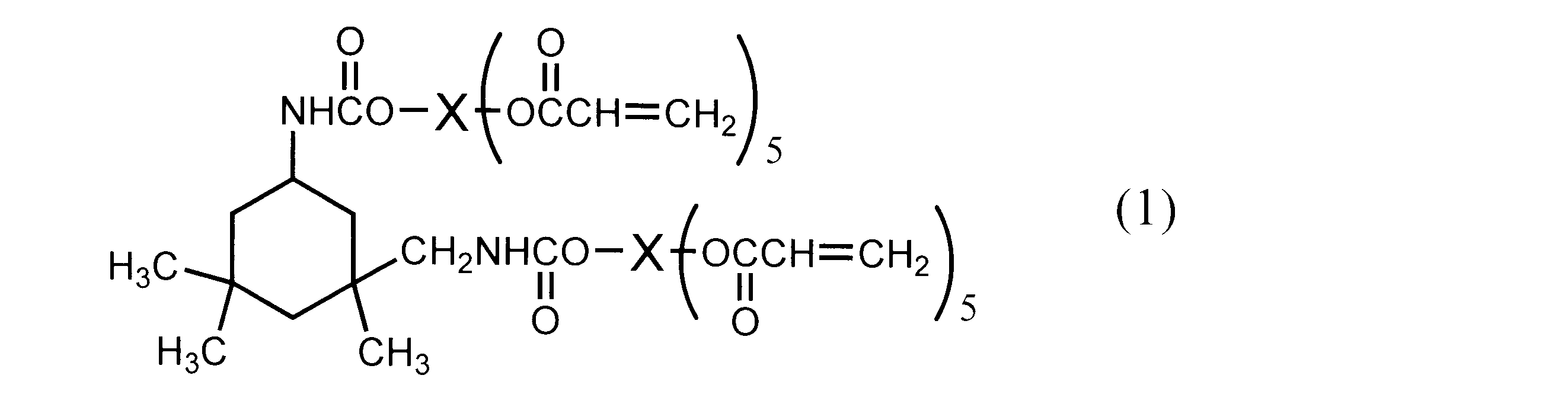
2HEA--IPDI--(アジピン酸と1,6-ヘキサンジオールとの重量平均分子量3500の末端水酸基のポリエステル)--IPDI--2HEA
で示される化合物である。ここで、「2HEA」は、2-ヒドロキシエチルアクリレートを示し、「IPDI」は、イソホロンジイソシアネートを示し、「--」は、イソシアネート基と水酸基の通常の下記の反応による結合を示す。
-NCO + HO- → -NHCOO- The compound (2) is
2HEA--IPDI-(polyester of terminal hydroxyl group having a weight average molecular weight of 3,500 of adipic acid and 1,6-hexanediol)-IPDI--2HEA
It is a compound shown by these. Here, “2HEA” represents 2-hydroxyethyl acrylate, “IPDI” represents isophorone diisocyanate, and “—” represents a bond between an isocyanate group and a hydroxyl group by the following normal reaction.
-NCO + HO- → -NHCOO-
実施例1において、アルミナ系の研摩材を用いて研摩する代わりに、ボールバフにより、コロイダルシリカ(フジミ研磨材社製)を主成分とする研摩材を用いて研摩した以外は、実施例1と同様にして反射防止膜を得た。 Example 2
In Example 1, instead of polishing using an alumina-based polishing material, the same as Example 1 except that polishing was performed using a polishing material mainly composed of colloidal silica (manufactured by Fujimi Abrasives) with a ball buff. Thus, an antireflection film was obtained.
実施例1においてアルミナ系の研摩材を用いて研摩する代わりに、バイアスバフ(光陽社製)により、無水ケイ酸系の油脂研摩材(イチグチ社製)を用いて研摩した以外は、実施例1と同様にして反射防止膜を得た。 Example 3
Instead of polishing with an alumina-based abrasive in Example 1, it was the same as in Example 1 except that it was polished with a silicic acid-based oil and fat abrasive (Ichiguchi) using a bias buff (manufactured by Koyo). Thus, an antireflection film was obtained.
実施例1においてアルミナ系の研摩材を用いて研摩する代わりに、正面精密旋盤に真空チャックにより固定し、天然ダイヤモンドバイトを用いて、鏡面切削する以外は、実施例1と同様にして反射防止膜を得た。 Example 4
Instead of polishing with an alumina-based polishing material in Example 1, an antireflection film was prepared in the same manner as in Example 1 except that it was fixed to a front precision lathe with a vacuum chuck and mirror-cut with a natural diamond tool. Got.
実施例1においてアルミナ系の研摩材を用いて研摩する代わりに、95℃、60体積%リン酸と5体積%硝酸の混合で得られる研摩液中で、3分間振動させながら処理する以外は、実施例1と同様にして反射防止膜を得た。 Example 5
Instead of polishing with an alumina-based polishing material in Example 1, the treatment was carried out in a polishing solution obtained by mixing at 95 ° C. and 60% by volume phosphoric acid and 5% by volume nitric acid while vibrating for 3 minutes. An antireflection film was obtained in the same manner as in Example 1.
実施例1においてアルミナ系の研摩材を用いて研摩する代わりに、70℃、90体積%リン酸浴中において、アルミ材をプラス極として40A/dm2の電流密度で5分間振動しながら電解し、その後、20℃の硝酸浴(市販の約68%硝酸を2倍に希釈)中に10分間浸漬して表面の酸化膜を溶解除去した以外は、実施例1と同様にして反射防止膜を得た。 Example 6
Instead of polishing with an alumina-based polishing material in Example 1, electrolysis was performed in a 90 ° C., 90% by volume phosphoric acid bath with an aluminum material as a positive electrode while vibrating at a current density of 40 A / dm 2 for 5 minutes. Thereafter, an antireflection film was formed in the same manner as in Example 1 except that the surface oxide film was dissolved and removed by immersion in a nitric acid bath at 20 ° C. (diluted about 68% of commercially available nitric acid twice) for 10 minutes. Obtained.
実施例1においてアルミナ系の研摩材を用いて研摩する代わりに、バイアスバフ(光陽社製)により、無水ケイ酸系の油脂研摩材(イチグチ社製)を用いて研摩し、引き続き、95℃、60体積%リン酸と5体積%硝酸の混合で得られる研摩液中で3分間振動しながら処理する以外は、実施例1と同様にして反射防止膜を得た。 Example 7
In Example 1, instead of polishing with an alumina-based abrasive, polishing was performed with a silicic acid-based oil and fat abrasive (manufactured by Ichiguchi) with a bias buff (manufactured by Koyo), followed by 95 ° C., 60 vol. An antireflection film was obtained in the same manner as in Example 1 except that the treatment was performed in a polishing liquid obtained by mixing 5% phosphoric acid and 5% by volume nitric acid while vibrating for 3 minutes.
実施例1においてアルミナ系の研摩材を用いて研摩する代わりに、ボールバフにより、コロイダルシリカを主成分とする研摩材を用いて研摩し、研摩面をスクラブ洗浄後、脱脂処理を行った後、70℃、90体積%リン酸浴中において、アルミニウム材をプラス極として40A/dm2の電流密度で5分間振動しながら電解し、その後、20℃の硝酸浴(市販の約68%硝酸を2倍に希釈)中に10分間浸漬して表面の酸化膜を溶解除去する以外は、実施例1と同様にして反射防止膜を得た。 Example 8
Instead of polishing with an alumina-based polishing material in Example 1, polishing was performed with a ball buff using a polishing material mainly composed of colloidal silica, and the polishing surface was scrubbed and degreased. In a 90 ° C., 90% by volume phosphoric acid bath, electrolysis was performed while vibrating for 5 minutes at a current density of 40 A / dm 2 using an aluminum material as a positive electrode, and then a nitric acid bath at 20 ° C. An antireflective film was obtained in the same manner as in Example 1 except that the surface oxide film was dissolved and removed by immersing in (diluted) for 10 minutes.
実施例1においてアルミナ系の研摩材を用いて研摩する代わりに、片面平面ラップ盤により、水溶性の研削液(ケメット・ジャパン製)を併用しながら準鏡面を研摩し、研摩面をスクラブ洗浄後、脱脂処理を行った後、70℃、90体積%リン酸浴中において、アルミ材をプラス極として40A/dm2の電流密度で5分間振動しながら電解し、その後、20℃の硝酸浴(市販の硝酸を2倍に希釈)中に10分間浸漬して表面の酸化膜を溶解除去する以外は、実施例1と同様にして反射防止膜を得た。 Example 9
Instead of polishing with an alumina-based polishing material in Example 1, the semi-mirror surface was polished with a single-sided flat lapping machine in combination with a water-soluble grinding fluid (manufactured by Kemet Japan), and the polished surface was scrubbed. After the degreasing treatment, electrolysis was performed in a phosphoric acid bath at 70 ° C. and 90% by volume with the aluminum material as a positive electrode while vibrating for 5 minutes at a current density of 40 A / dm 2 , and then a nitric acid bath at 20 ° C. ( An antireflection film was obtained in the same manner as in Example 1 except that the surface oxide film was dissolved and removed by immersing in commercially available nitric acid (diluted twice) for 10 minutes.
実施例1において、99.85%のアルミニウム圧延板(2mm厚)をアルミナ系の研摩材を用いて研摩する代わりに、アルミニウム合金5005押出管(外径30mm)を精密旋盤(エグロ社製)と単結晶ダイヤモンドバイト(東京ダイヤモンド社製)を用いて、灯油を潤滑剤として高速回転で旋盤加工を施した以外は、実施例1と同様にして反射防止膜を得た。 Example 10
In Example 1, instead of polishing a 99.85% rolled aluminum plate (2 mm thick) with an alumina-based abrasive, an aluminum alloy 5005 extruded tube (outer diameter 30 mm) was replaced with a precision lathe (manufactured by Egro). An antireflection film was obtained in the same manner as in Example 1 except that a single crystal diamond tool (manufactured by Tokyo Diamond Co., Ltd.) was used and lathe processing was performed at high speed rotation using kerosene as a lubricant.
実施例1において、99.85%のアルミニウム圧延板(2mm厚)をアルミナ系の研摩材を用いて研摩する代わりに、アルミニウム合金5005の改良合金の引き抜き管(外径30mm)を精密旋盤とコンパックスダイヤモンドバイトを用いて、灯油を潤滑剤として高速回転で旋盤加工を施し、引き続き、70℃、90体積%リン酸浴中において、アルミ材をプラス極として40A/dm2の電流密度で5分間振動しながら電解し、その後、20℃の硝酸浴(市販の約68%硝酸を2倍に希釈)中に10分間浸漬して表面の酸化膜を溶解除去する以外は、実施例1と同様にして反射防止膜を得た。 Example 11
In Example 1, instead of polishing a 99.85% rolled aluminum sheet (2 mm thick) with an alumina-based abrasive, an improved alloy drawing tube (outer diameter 30 mm) of aluminum alloy 5005 was used as a precision lathe and Compaq. Using a diamond bite, lathe processing was performed at high speed with kerosene as a lubricant, and then in a 90% by volume phosphoric acid bath at 70 ° C. for 5 minutes at a current density of 40 A / dm 2 with aluminum as the positive electrode. The same as in Example 1 except that the electrolysis was performed with vibration, and the surface oxide film was dissolved and removed by dipping in a 20 ° C. nitric acid bath (commercially about 68% nitric acid diluted twice) for 10 minutes. Thus, an antireflection film was obtained.
実施例1において、光硬化性組成物(a)を用いる代わりに表1記載の光硬化性組成物(b)~(g)を用いる以外は、実施例1と同様にして反射防止膜を得た。 Example 12
In Example 1, an antireflection film was obtained in the same manner as in Example 1 except that the photocurable compositions (b) to (g) shown in Table 1 were used instead of using the photocurable composition (a). It was.
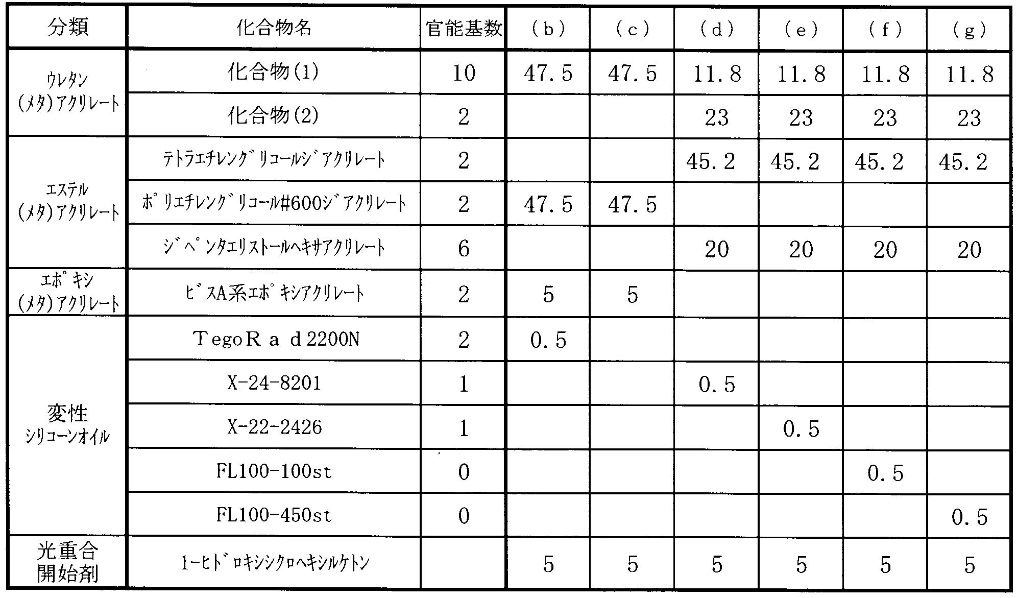
実施例1において、アルミナ系の研摩材を用いて研摩しない以外は、実施例1と同様にして反射防止膜を得た。 Comparative Example 1
In Example 1, an antireflection film was obtained in the same manner as in Example 1 except that polishing was not performed using an alumina-based abrasive.
実施例5において、リン酸と硝酸の研摩液中で処理しない以外は、実施例5と同様にして反射防止膜を得た。 Comparative Example 2
In Example 5, an antireflection film was obtained in the same manner as in Example 5 except that the treatment was not performed in a polishing solution of phosphoric acid and nitric acid.
実施例6において、リン酸浴中で電解しない以外は、実施例6と同様にして反射防止膜を得た。 Comparative Example 3
In Example 6, an antireflection film was obtained in the same manner as in Example 6 except that electrolysis was not performed in a phosphoric acid bath.
[Ra、Ry]
実施例1~11で得られた「機械研摩、化学研摩及び/又は電解研摩により加工した後のアルミニウム材料」の表面のRa及びRyの値を、比較例の「アルミニウム材料」の表面のRa及びRyの値と共に以下に示す。Ra及びRyは、JIS B0601(1994)に従って測定した。
NO. Ra(μm) Ry(μm)
実施例1 0.035 0.45
実施例2 0.035 0.45
実施例3 0.034 0.45
実施例4 0.035 0.44
実施例5 0.034 0.45
実施例6 0.032 0.38
実施例7 0.033 0.27
実施例8 0.029 0.27
実施例9 0.018 0.19
実施例10 0.035 0.45
実施例11 0.022 0.19
比較例1 0.50 2.00
比較例2 0.50 2.00
比較例3 0.50 2.00 <Evaluation>
[Ra, Ry]
The Ra and Ry values of the surface of the “aluminum material after being processed by mechanical polishing, chemical polishing and / or electrolytic polishing” obtained in Examples 1 to 11, and the Ra and Ry values of the surface of the comparative “aluminum material” It is shown below with the value of Ry. Ra and Ry were measured according to JIS B0601 (1994).
NO. Ra (μm) Ry (μm)
Example 1 0.035 0.45
Example 2 0.035 0.45
Example 3 0.034 0.45
Example 4 0.035 0.44
Example 5 0.034 0.45
Example 6 0.032 0.38
Example 7 0.033 0.27
Example 8 0.029 0.27
Example 9 0.018 0.19
Example 10 0.035 0.45
Example 11 0.022 0.19
Comparative Example 1 0.50 2.00
Comparative Example 2 0.50 2.00
Comparative Example 3 0.50 2.00
スガ試験機社製、ヘイズメーター「HGM-2DP」を用いて、可視光線のヘイズを測定した。 [Haze]
Using a haze meter “HGM-2DP” manufactured by Suga Test Instruments Co., Ltd., the haze of visible light was measured.
反射防止膜の透明性は、以下の基準により目視で評価判定した。
◎:透明性が極めて良好
○:透明性が良好
△:やや透明性が低いが合格レベル
×:透明性が不良 [transparency]
The transparency of the antireflection film was visually evaluated and determined according to the following criteria.
◎: Very good transparency ○: Good transparency △: Slightly low transparency but acceptable level ×: Poor transparency
島津製作所社製、自記分光光度計「UV-3150」を用い、裏面に黒色テープを貼り付け、5°入射絶対反射率を測定した。 [Reflectance]
Using a self-recording spectrophotometer “UV-3150” manufactured by Shimadzu Corporation, a black tape was attached to the back surface, and the 5 ° incident absolute reflectance was measured.
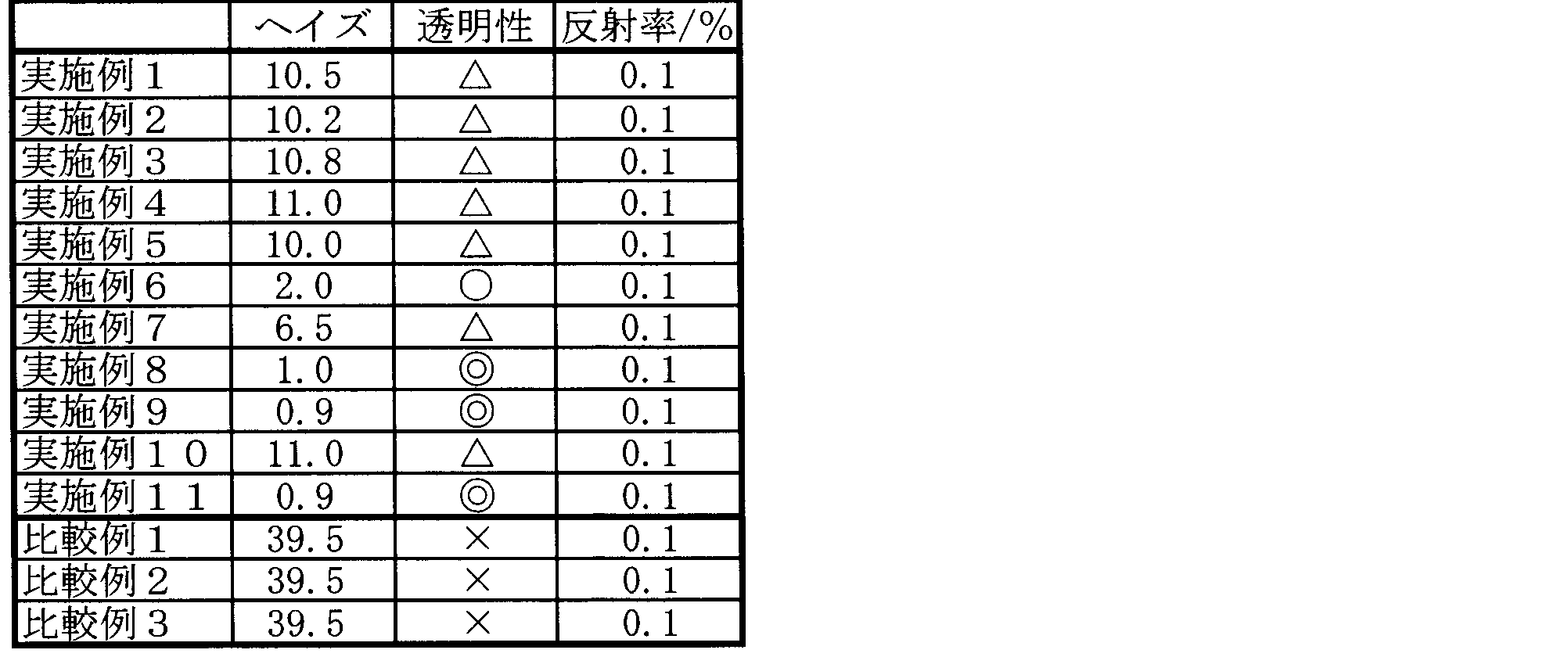
2 型
3 基材
4 ローラー
5 反射防止膜
6 硬化装置
7 支持ローラー DESCRIPTION OF
Claims (7)
- アルミニウム材料の表面を、機械研摩、化学研摩及び/又は電解研摩により加工した後、該アルミニウム材料の表面に、陽極酸化と陽極酸化被膜のエッチングとの組み合わせによりテーパー形状の細孔を有する型を作製し、この型を反射防止膜形成材料に転写させることによって得られ、その表面に平均高さ100nm以上1000nm以下の凸部又は平均深さ100nm以上1000nm以下の凹部を有し、その凸部又は凹部が、少なくともある一の方向に対し平均周期50nm以上400nm以下で存在し、かつヘイズが15%以下であることを特徴とする反射防止膜。 After processing the surface of the aluminum material by mechanical polishing, chemical polishing and / or electrolytic polishing, a mold having tapered pores is produced on the surface of the aluminum material by a combination of anodization and etching of the anodized film. The mold is transferred to an antireflection film-forming material, and has a convex portion having an average height of 100 nm to 1000 nm or a concave portion having an average depth of 100 nm to 1000 nm on the surface thereof. Is present at an average period of 50 nm or more and 400 nm or less with respect to at least one direction, and a haze is 15% or less.
- 機械研摩、化学研摩及び/又は電解研摩により加工した後のアルミニウム材料の表面が、算術平均粗さRaとして0.1μm以下のものである請求項1記載の反射防止膜。 The antireflection film according to claim 1, wherein the surface of the aluminum material after being processed by mechanical polishing, chemical polishing and / or electrolytic polishing has an arithmetic average roughness Ra of 0.1 μm or less.
- 上記陽極酸化が、シュウ酸濃度0.01M以上0.5M以下、印加電圧20V以上120V以下、かつ液温0℃以上50℃以下で行われるものである請求項1又は請求項2記載の反射防止膜。 The antireflection according to claim 1 or 2, wherein the anodic oxidation is performed at an oxalic acid concentration of 0.01 M to 0.5 M, an applied voltage of 20 V to 120 V, and a liquid temperature of 0 ° C to 50 ° C. film.
- 上記エッチングが、リン酸濃度1重量%以上20重量%以下、液温30℃以上90℃以下、かつ1回の処理時間1分以上60分以下で行われるものである請求項1又は請求項2記載の反射防止膜。 3. The etching is performed at a phosphoric acid concentration of 1% by weight to 20% by weight, a liquid temperature of 30 ° C. to 90 ° C., and a single treatment time of 1 minute to 60 minutes. The antireflection film as described.
- 上記反射防止膜形成材料が、光照射、電子線照射及び/又は加熱によって硬化する硬化性組成物である請求項1又は請求項2記載の反射防止膜。 The antireflection film according to claim 1 or 2, wherein the antireflection film forming material is a curable composition that is cured by light irradiation, electron beam irradiation and / or heating.
- 上記硬化性組成物が、アクリル系重合性組成物又はメタクリル系重合性組成物である請求項5に記載の反射防止膜。 6. The antireflection film according to claim 5, wherein the curable composition is an acrylic polymerizable composition or a methacrylic polymerizable composition.
- 請求項1又は請求項2記載の反射防止膜形成用のテーパー形状の細孔を有する型であって、シュウ酸濃度0.01M以上0.5M以下、印加電圧20V以上120V以下、かつ液温0℃以上50℃以下で行う陽極酸化と、リン酸濃度1重量%以上20重量%以下、液温30℃以上90℃以下、かつ1回の処理時間1分以上60分以下で行うエッチングとの組み合わせにより作製されたものであることを特徴とするテーパー形状の細孔を有する型。 A mold having tapered pores for forming an antireflection film according to claim 1 or 2, wherein the oxalic acid concentration is 0.01 M or more and 0.5 M or less, the applied voltage is 20 V or more and 120 V or less, and the liquid temperature is 0. A combination of anodic oxidation performed at a temperature of 50 ° C. to 50 ° C. and etching performed at a phosphoric acid concentration of 1% to 20% by weight, a liquid temperature of 30 ° C. to 90 ° C., and a processing time of 1 minute to 60 minutes. A mold having tapered pores, which is manufactured by the method described above.
Priority Applications (3)
| Application Number | Priority Date | Filing Date | Title |
|---|---|---|---|
| CN2009801190975A CN102047149A (en) | 2008-05-27 | 2009-05-12 | Antireflection film and process for producing the antireflection film |
| US12/994,807 US20110157704A1 (en) | 2008-05-27 | 2009-05-12 | Antireflective film and production method thereof |
| EP09754557A EP2293119A4 (en) | 2008-05-27 | 2009-05-12 | Antireflection film and process for producing the antireflection film |
Applications Claiming Priority (2)
| Application Number | Priority Date | Filing Date | Title |
|---|---|---|---|
| JP2008138444A JP5254664B2 (en) | 2008-05-27 | 2008-05-27 | Antireflection film and method for manufacturing the same |
| JP2008-138444 | 2008-05-27 |
Publications (1)
| Publication Number | Publication Date |
|---|---|
| WO2009145049A1 true WO2009145049A1 (en) | 2009-12-03 |
Family
ID=41376934
Family Applications (1)
| Application Number | Title | Priority Date | Filing Date |
|---|---|---|---|
| PCT/JP2009/058810 WO2009145049A1 (en) | 2008-05-27 | 2009-05-12 | Antireflection film and process for producing the antireflection film |
Country Status (7)
| Country | Link |
|---|---|
| US (1) | US20110157704A1 (en) |
| EP (1) | EP2293119A4 (en) |
| JP (1) | JP5254664B2 (en) |
| KR (1) | KR101376350B1 (en) |
| CN (1) | CN102047149A (en) |
| TW (1) | TWI406048B (en) |
| WO (1) | WO2009145049A1 (en) |
Cited By (9)
| Publication number | Priority date | Publication date | Assignee | Title |
|---|---|---|---|---|
| JP2012037670A (en) * | 2010-08-05 | 2012-02-23 | Dainippon Printing Co Ltd | Manufacturing method of mold for producing antireflection film |
| CN102398338A (en) * | 2010-09-17 | 2012-04-04 | 奇美实业股份有限公司 | Manufacturing method of micro-structure optical plate with high transferring rate |
| WO2012087663A1 (en) * | 2010-12-20 | 2012-06-28 | 3M Innovative Properties Company | Glass-like polymeric antireflective films coated with silica nanoparticles, methods of making and light absorbing devices using same |
| CN102759764A (en) * | 2011-04-25 | 2012-10-31 | 奇美实业股份有限公司 | Manufacturing method of micro-structural optical plate with high transcription rate and forming device thereof |
| TWI448379B (en) * | 2010-11-12 | 2014-08-11 | Chi Mei Corp | The manufacturing method of the optical plate |
| JP2014522504A (en) * | 2011-06-03 | 2014-09-04 | マクダーミッド オートタイプ リミテッド | Conductive antireflection film |
| WO2015022916A1 (en) * | 2013-08-14 | 2015-02-19 | 三菱レイヨン株式会社 | Method for producing mold for nanoimprinting and anti-reflective article |
| WO2015022935A1 (en) * | 2013-08-14 | 2015-02-19 | 三菱レイヨン株式会社 | Method for producing cylindrical nanoimprinting mold and method for producing nanoimprinting reproduction mold |
| US9896557B2 (en) | 2010-04-28 | 2018-02-20 | 3M Innovative Properties Company | Silicone-based material |
Families Citing this family (21)
| Publication number | Priority date | Publication date | Assignee | Title |
|---|---|---|---|---|
| JP5229206B2 (en) * | 2009-12-18 | 2013-07-03 | 大日本印刷株式会社 | Method for producing antireflection film |
| JP4985754B2 (en) * | 2009-12-18 | 2012-07-25 | 大日本印刷株式会社 | Antireflection film manufacturing method and manufacturing apparatus |
| WO2011105206A1 (en) * | 2010-02-24 | 2011-09-01 | シャープ株式会社 | Die, die production method, and production of antireflection film |
| TWI443011B (en) * | 2011-07-29 | 2014-07-01 | Chi Mei Corp | Duplex microstructure optical plate forming apparatus and manufacturing method thereof |
| JP5821205B2 (en) * | 2011-02-04 | 2015-11-24 | ソニー株式会社 | OPTICAL ELEMENT AND ITS MANUFACTURING METHOD, DISPLAY DEVICE, INFORMATION INPUT DEVICE, AND PHOTO |
| JP6048145B2 (en) * | 2011-09-08 | 2016-12-21 | 三菱レイヨン株式会社 | Transparent film having fine concavo-convex structure on surface, and production method thereof |
| JPWO2013054832A1 (en) * | 2011-10-14 | 2015-03-30 | 三菱レイヨン株式会社 | Method for manufacturing roll-shaped mold for optical sheet manufacturing, optical sheet manufacturing method, electronic display device, and mirror finishing method for aluminum base material |
| TW201325884A (en) * | 2011-12-29 | 2013-07-01 | Hon Hai Prec Ind Co Ltd | Pressing roller for producing optical film and manufacturing method of the press roller |
| JP2013142823A (en) * | 2012-01-11 | 2013-07-22 | Dainippon Printing Co Ltd | Light antireflection article |
| WO2013137251A1 (en) * | 2012-03-15 | 2013-09-19 | 綜研化学株式会社 | Anti-reflection film |
| US9218516B2 (en) | 2012-06-08 | 2015-12-22 | Datalogic ADC, Inc. | Data reader platter with integral features delineating a data-reading sweep region |
| WO2015041283A1 (en) * | 2013-09-18 | 2015-03-26 | 三菱レイヨン株式会社 | Structure, production method therefor, and article provided with said structure |
| JP6324048B2 (en) * | 2013-12-11 | 2018-05-16 | 旭化成株式会社 | Functional transfer body, method of transferring functional layer, solar cell and method of manufacturing the same |
| JP2015079262A (en) * | 2014-11-28 | 2015-04-23 | 大日本印刷株式会社 | Antireflection film |
| JP6482120B2 (en) | 2015-03-31 | 2019-03-13 | デクセリアルズ株式会社 | Master production method, optical body production method, optical member production method, and display device production method |
| JP6689576B2 (en) | 2015-03-31 | 2020-04-28 | デクセリアルズ株式会社 | Master manufacturing method, master, and optical body |
| KR101951863B1 (en) | 2016-03-14 | 2019-02-25 | 주식회사 엘지화학 | Anti-reflective film and display device |
| KR101951864B1 (en) * | 2016-03-14 | 2019-02-25 | 주식회사 엘지화학 | Anti-reflective film and display device |
| KR101948821B1 (en) | 2016-03-14 | 2019-02-15 | 주식회사 엘지화학 | Anti-reflective film and display device |
| JP7354287B2 (en) * | 2019-04-26 | 2023-10-02 | 華為技術有限公司 | Anti-reflection coatings, optical elements, camera modules, and terminals |
| TWI727683B (en) * | 2020-02-27 | 2021-05-11 | 態金材料科技股份有限公司 | Manufacturing method and products of anti-reflective optical glass |
Citations (16)
| Publication number | Priority date | Publication date | Assignee | Title |
|---|---|---|---|---|
| JPS5070040A (en) | 1973-05-10 | 1975-06-11 | ||
| JPH09193332A (en) | 1996-01-16 | 1997-07-29 | Dainippon Printing Co Ltd | Glare protecting film |
| JP2003043203A (en) | 2001-08-01 | 2003-02-13 | Hitachi Maxell Ltd | Antireflection film, method for manufacturing the same, stamper for manufacture of antireflection film, method for manufacturing the stamper, casting mold for manufacture of stamper and method for manufacturing the casting mold |
| JP2003162205A (en) | 2001-09-14 | 2003-06-06 | Dainippon Printing Co Ltd | Photosetting resin composition, sheet, transfer foil, method of forming fine rugged pattern and optical article |
| JP2003215314A (en) | 2002-01-18 | 2003-07-30 | Dainippon Printing Co Ltd | Antireflection article |
| JP2003240903A (en) | 2002-02-20 | 2003-08-27 | Dainippon Printing Co Ltd | Antireflection article |
| JP2004004515A (en) | 2002-03-29 | 2004-01-08 | Dainippon Printing Co Ltd | Material for forming fine rugged pattern, method of forming fine rugged pattern, transfer foil, optical article, and stamper |
| JP2004059820A (en) | 2002-07-31 | 2004-02-26 | Dainippon Printing Co Ltd | Photosetting resin, photosetting resin composition, method for forming minute uneven pattern, transfer foil, optical article and stamper |
| JP2004059822A (en) | 2002-07-31 | 2004-02-26 | Dainippon Printing Co Ltd | Photocurable resin, photocurable resin composition, method of forming fine concave-convex pattern, transfer foil, optical article, and stamper |
| JP2005010231A (en) | 2003-06-16 | 2005-01-13 | Dainippon Printing Co Ltd | Rugged pattern forming material, rugged pattern receiving body, rugged pattern forming method, transfer foil, and optical component |
| JP2005092099A (en) | 2003-09-19 | 2005-04-07 | Fuji Photo Film Co Ltd | Curable resin composition and optical article, and image display device using the same |
| JP2005156695A (en) | 2003-11-21 | 2005-06-16 | Kanagawa Acad Of Sci & Technol | Anti-reflection coating and method for manufacturing the same, and stamper for preparing anti-reflection coating and method for manufacturing the same |
| JP2006283058A (en) * | 2005-03-31 | 2006-10-19 | Fuji Photo Film Co Ltd | Fine structure |
| JP2007086283A (en) | 2005-09-21 | 2007-04-05 | Kanagawa Acad Of Sci & Technol | Antireflection film and method for manufacturing same, and stamper for preparing antireflection film and method for manufacturing same |
| WO2008001847A1 (en) * | 2006-06-30 | 2008-01-03 | Mitsubishi Rayon Co., Ltd. | Mold, process for manufacturing mold, and process for producing sheet |
| JP2008138444A (en) | 2006-12-01 | 2008-06-19 | I K G:Kk | Ridge structure, and ridge construction method |
Family Cites Families (4)
| Publication number | Priority date | Publication date | Assignee | Title |
|---|---|---|---|---|
| KR100705181B1 (en) * | 2004-03-16 | 2007-04-06 | 주식회사 엘지화학 | Highly efficient organic light emitting device using substrate or electrode having nanosized half-spherical convex and method for preparing the same |
| JP2005329451A (en) * | 2004-05-21 | 2005-12-02 | Fuji Photo Film Co Ltd | Method for working surface of aluminum plate, base material for lithographic printing plate and lithographic printing plate |
| JP4368384B2 (en) * | 2004-12-03 | 2009-11-18 | シャープ株式会社 | Antireflection material, optical element, display device, stamper manufacturing method, and antireflection material manufacturing method using stamper |
| ATE461239T1 (en) * | 2006-04-07 | 2010-04-15 | Ems Chemie Ag | TRANSPARENT, AMORPHOUS POLYAMIDE MOLDING COMPOUNDS AND THEIR USE |
-
2008
- 2008-05-27 JP JP2008138444A patent/JP5254664B2/en not_active Expired - Fee Related
-
2009
- 2009-05-12 EP EP09754557A patent/EP2293119A4/en not_active Withdrawn
- 2009-05-12 WO PCT/JP2009/058810 patent/WO2009145049A1/en active Application Filing
- 2009-05-12 US US12/994,807 patent/US20110157704A1/en not_active Abandoned
- 2009-05-12 KR KR1020107026452A patent/KR101376350B1/en not_active IP Right Cessation
- 2009-05-12 CN CN2009801190975A patent/CN102047149A/en active Pending
- 2009-05-13 TW TW098115782A patent/TWI406048B/en not_active IP Right Cessation
Patent Citations (16)
| Publication number | Priority date | Publication date | Assignee | Title |
|---|---|---|---|---|
| JPS5070040A (en) | 1973-05-10 | 1975-06-11 | ||
| JPH09193332A (en) | 1996-01-16 | 1997-07-29 | Dainippon Printing Co Ltd | Glare protecting film |
| JP2003043203A (en) | 2001-08-01 | 2003-02-13 | Hitachi Maxell Ltd | Antireflection film, method for manufacturing the same, stamper for manufacture of antireflection film, method for manufacturing the stamper, casting mold for manufacture of stamper and method for manufacturing the casting mold |
| JP2003162205A (en) | 2001-09-14 | 2003-06-06 | Dainippon Printing Co Ltd | Photosetting resin composition, sheet, transfer foil, method of forming fine rugged pattern and optical article |
| JP2003215314A (en) | 2002-01-18 | 2003-07-30 | Dainippon Printing Co Ltd | Antireflection article |
| JP2003240903A (en) | 2002-02-20 | 2003-08-27 | Dainippon Printing Co Ltd | Antireflection article |
| JP2004004515A (en) | 2002-03-29 | 2004-01-08 | Dainippon Printing Co Ltd | Material for forming fine rugged pattern, method of forming fine rugged pattern, transfer foil, optical article, and stamper |
| JP2004059820A (en) | 2002-07-31 | 2004-02-26 | Dainippon Printing Co Ltd | Photosetting resin, photosetting resin composition, method for forming minute uneven pattern, transfer foil, optical article and stamper |
| JP2004059822A (en) | 2002-07-31 | 2004-02-26 | Dainippon Printing Co Ltd | Photocurable resin, photocurable resin composition, method of forming fine concave-convex pattern, transfer foil, optical article, and stamper |
| JP2005010231A (en) | 2003-06-16 | 2005-01-13 | Dainippon Printing Co Ltd | Rugged pattern forming material, rugged pattern receiving body, rugged pattern forming method, transfer foil, and optical component |
| JP2005092099A (en) | 2003-09-19 | 2005-04-07 | Fuji Photo Film Co Ltd | Curable resin composition and optical article, and image display device using the same |
| JP2005156695A (en) | 2003-11-21 | 2005-06-16 | Kanagawa Acad Of Sci & Technol | Anti-reflection coating and method for manufacturing the same, and stamper for preparing anti-reflection coating and method for manufacturing the same |
| JP2006283058A (en) * | 2005-03-31 | 2006-10-19 | Fuji Photo Film Co Ltd | Fine structure |
| JP2007086283A (en) | 2005-09-21 | 2007-04-05 | Kanagawa Acad Of Sci & Technol | Antireflection film and method for manufacturing same, and stamper for preparing antireflection film and method for manufacturing same |
| WO2008001847A1 (en) * | 2006-06-30 | 2008-01-03 | Mitsubishi Rayon Co., Ltd. | Mold, process for manufacturing mold, and process for producing sheet |
| JP2008138444A (en) | 2006-12-01 | 2008-06-19 | I K G:Kk | Ridge structure, and ridge construction method |
Non-Patent Citations (1)
| Title |
|---|
| See also references of EP2293119A4 |
Cited By (17)
| Publication number | Priority date | Publication date | Assignee | Title |
|---|---|---|---|---|
| US9896557B2 (en) | 2010-04-28 | 2018-02-20 | 3M Innovative Properties Company | Silicone-based material |
| JP2012037670A (en) * | 2010-08-05 | 2012-02-23 | Dainippon Printing Co Ltd | Manufacturing method of mold for producing antireflection film |
| CN102398338A (en) * | 2010-09-17 | 2012-04-04 | 奇美实业股份有限公司 | Manufacturing method of micro-structure optical plate with high transferring rate |
| CN102398338B (en) * | 2010-09-17 | 2014-02-26 | 奇美实业股份有限公司 | Manufacturing method of micro-structure optical plate with high transferring rate |
| TWI448379B (en) * | 2010-11-12 | 2014-08-11 | Chi Mei Corp | The manufacturing method of the optical plate |
| WO2012087663A1 (en) * | 2010-12-20 | 2012-06-28 | 3M Innovative Properties Company | Glass-like polymeric antireflective films coated with silica nanoparticles, methods of making and light absorbing devices using same |
| CN103270433A (en) * | 2010-12-20 | 2013-08-28 | 3M创新有限公司 | Glass-like polymeric antireflective films coated with silica nanoparticles, methods of making and light absorbing devices using same |
| CN103270433B (en) * | 2010-12-20 | 2016-06-08 | 3M创新有限公司 | Scribble the hyaloid polymeric antireflective film of nano SiO 2 particle, preparation method and use the light absorbing device of this film |
| CN102759764B (en) * | 2011-04-25 | 2014-09-24 | 奇美实业股份有限公司 | Manufacturing method of micro-structural optical plate with high transcription rate and forming device thereof |
| CN102759764A (en) * | 2011-04-25 | 2012-10-31 | 奇美实业股份有限公司 | Manufacturing method of micro-structural optical plate with high transcription rate and forming device thereof |
| JP2014522504A (en) * | 2011-06-03 | 2014-09-04 | マクダーミッド オートタイプ リミテッド | Conductive antireflection film |
| WO2015022916A1 (en) * | 2013-08-14 | 2015-02-19 | 三菱レイヨン株式会社 | Method for producing mold for nanoimprinting and anti-reflective article |
| WO2015022935A1 (en) * | 2013-08-14 | 2015-02-19 | 三菱レイヨン株式会社 | Method for producing cylindrical nanoimprinting mold and method for producing nanoimprinting reproduction mold |
| US9457493B2 (en) | 2013-08-14 | 2016-10-04 | Mitsubishi Rayon Co., Ltd. | Method for producing cylindrical nanoimprinting mold and method for producing nanoimprinting reproduction mold |
| JPWO2015022935A1 (en) * | 2013-08-14 | 2017-03-02 | 三菱レイヨン株式会社 | Method for producing cylindrical nanoimprint mold and method for producing regenerated mold for nanoimprint |
| US9890466B2 (en) | 2013-08-14 | 2018-02-13 | Mitsubishi Chemical Corporation | Method for producing mold for nanoimprinting and anti-reflective article |
| KR101879797B1 (en) * | 2013-08-14 | 2018-07-18 | 미쯔비시 케미컬 주식회사 | Method for producing cylindrical nanoimprinting mold and method for producing nanoimprinting reproduction mold |
Also Published As
| Publication number | Publication date |
|---|---|
| EP2293119A1 (en) | 2011-03-09 |
| TW201001011A (en) | 2010-01-01 |
| US20110157704A1 (en) | 2011-06-30 |
| CN102047149A (en) | 2011-05-04 |
| KR101376350B1 (en) | 2014-03-20 |
| TWI406048B (en) | 2013-08-21 |
| KR20100135950A (en) | 2010-12-27 |
| JP2009288337A (en) | 2009-12-10 |
| JP5254664B2 (en) | 2013-08-07 |
| EP2293119A4 (en) | 2012-05-09 |
Similar Documents
| Publication | Publication Date | Title |
|---|---|---|
| JP5254664B2 (en) | Antireflection film and method for manufacturing the same | |
| JP5362826B2 (en) | Method for producing an article in which a cured resin layer having a fine relief structure is formed on the surface of a substrate | |
| KR101879827B1 (en) | Method for producing mold for nanoimprinting and anti-reflective article | |
| KR20130026450A (en) | Method for producing article having fine recessed and projected structure on surface, mold release treatment method for mold, and active energy ray-curable resin composition for mold surface release treatment | |
| JP2011002759A (en) | Antireflection film | |
| JP2009272557A (en) | Method and apparatus for manufacturing wafer, and curable resin composition | |
| KR20120049232A (en) | Antireflection article and display device | |
| JP6686284B2 (en) | Article containing cured product of active energy ray curable resin composition | |
| JP2010044184A (en) | Transparent molded body | |
| JP5616036B2 (en) | Laminate formed by laminating a substrate, an intermediate film, and a fine relief structure film | |
| TW201318805A (en) | Manufacturing method of optical sheet, manufacturing method of mold for manufacturing optical sheet, electronic display device and method of mirror finishing | |
| JPWO2011118591A1 (en) | Method for producing mold and method for producing article having fine uneven structure on surface | |
| JP2013210638A (en) | Antireflection film and production method of the same | |
| JP6455127B2 (en) | Production method of transparent film | |
| JP2015068944A (en) | Anti-reflection articles | |
| JP2014077040A (en) | Active energy ray-curable composition and fine uneven structure using the same | |
| JP2012108502A (en) | Method for manufacturing article having fine relief structure on surface | |
| JP5616191B2 (en) | Mold for producing nanostructure and method for producing the same | |
| JP5750755B2 (en) | Mold for producing nanostructure and method for producing the same | |
| JP2014126761A (en) | Laminate and manufacturing method therefor | |
| JP2012139899A (en) | (meth)acrylate-based polymerizable composition, antireflection film laminate using the same, and method for manufacturing the same | |
| KR101279521B1 (en) | Method of manufacturing a aluminum hard mold-type antistatic diffusion sheet having high luminance and high haze and without a bead, and a diffusion sheet manufactured by the same | |
| TW201641577A (en) | Active energy ray-curable resin composition and article | |
| WO2018186241A1 (en) | Multilayer body, reflection preventing article having three-dimensional curved surface, and method for manufacturing reflection preventing article | |
| JP2013112892A (en) | Method and apparatus of manufacturing mold for manufacturing nanostructure, mold for manufacturing nanostructure and nanostructure |
Legal Events
| Date | Code | Title | Description |
|---|---|---|---|
| WWE | Wipo information: entry into national phase |
Ref document number: 200980119097.5 Country of ref document: CN |
|
| 121 | Ep: the epo has been informed by wipo that ep was designated in this application |
Ref document number: 09754557 Country of ref document: EP Kind code of ref document: A1 |
|
| ENP | Entry into the national phase |
Ref document number: 20107026452 Country of ref document: KR Kind code of ref document: A |
|
| NENP | Non-entry into the national phase |
Ref country code: DE |
|
| WWE | Wipo information: entry into national phase |
Ref document number: 2009754557 Country of ref document: EP |