WO2009116386A1 - 室内暖房放熱器用の電気ヒーターユニットボックス - Google Patents
室内暖房放熱器用の電気ヒーターユニットボックス Download PDFInfo
- Publication number
- WO2009116386A1 WO2009116386A1 PCT/JP2009/053948 JP2009053948W WO2009116386A1 WO 2009116386 A1 WO2009116386 A1 WO 2009116386A1 JP 2009053948 W JP2009053948 W JP 2009053948W WO 2009116386 A1 WO2009116386 A1 WO 2009116386A1
- Authority
- WO
- WIPO (PCT)
- Prior art keywords
- heater unit
- unit box
- connection port
- side plate
- pipe
- Prior art date
- Legal status (The legal status is an assumption and is not a legal conclusion. Google has not performed a legal analysis and makes no representation as to the accuracy of the status listed.)
- Ceased
Links
Images


Classifications
-
- F—MECHANICAL ENGINEERING; LIGHTING; HEATING; WEAPONS; BLASTING
- F24—HEATING; RANGES; VENTILATING
- F24H—FLUID HEATERS, e.g. WATER OR AIR HEATERS, HAVING HEAT-GENERATING MEANS, e.g. HEAT PUMPS, IN GENERAL
- F24H3/00—Air heaters
- F24H3/002—Air heaters using electric energy supply
- F24H3/004—Air heaters using electric energy supply with a closed circuit for a heat transfer liquid
-
- F—MECHANICAL ENGINEERING; LIGHTING; HEATING; WEAPONS; BLASTING
- F24—HEATING; RANGES; VENTILATING
- F24D—DOMESTIC- OR SPACE-HEATING SYSTEMS, e.g. CENTRAL HEATING SYSTEMS; DOMESTIC HOT-WATER SUPPLY SYSTEMS; ELEMENTS OR COMPONENTS THEREFOR
- F24D19/00—Details
- F24D19/06—Casings, cover lids or ornamental panels, for radiators
-
- F—MECHANICAL ENGINEERING; LIGHTING; HEATING; WEAPONS; BLASTING
- F24—HEATING; RANGES; VENTILATING
- F24D—DOMESTIC- OR SPACE-HEATING SYSTEMS, e.g. CENTRAL HEATING SYSTEMS; DOMESTIC HOT-WATER SUPPLY SYSTEMS; ELEMENTS OR COMPONENTS THEREFOR
- F24D3/00—Hot-water central heating systems
- F24D3/10—Feed-line arrangements, e.g. providing for heat-accumulator tanks, expansion tanks ; Hydraulic components of a central heating system
- F24D3/1008—Feed-line arrangements, e.g. providing for heat-accumulator tanks, expansion tanks ; Hydraulic components of a central heating system expansion tanks
Definitions
- the present invention relates to an electric heater unit box in which equipment is housed in a unit box for use by being connected to a hot water circulation radiator for indoor heating, and belongs to the technical field of indoor heating of buildings. .
- FIG. 6 is a schematic explanatory diagram of the heating system
- FIG. 6C is a side view of the heat dissipating part.
- the hot water boiler 100 including the pressure gauge 103, the safety relief valve, the water supply port 101, and the drain port 102 is heated by electricity, gas, etc., and the hot water heated by the hot water boiler is Water is supplied to the radiator HR of the metal panel MP disposed in each living room via the pipe P and the outgoing header 107 to heat the room, and the boiler 100 supplies hot water from each radiator HR via the pipe P and the return header 108.
- a circulation pump 104, a sealed expansion tank 105, an air vent valve, headers 107 and 108, etc. are housed, and each radiator HR also includes an air vent valve Va, A thermo stud valve Vt and a hot water inlet / outlet valve V are arranged, and one hot water circulation system arranged in the center is connected to a large number of radiators HR.
- FIG. 7 is an electric water heater EHR cited in Patent Document 1, and as shown in FIG. 7, a large number of radiating fins 202 are arranged on the outer peripheral surface of the heating copper tube 201.
- a sheathed heater 204 is disposed over almost the entire length of the heating copper tube, and the heating chamber 203 is filled with the aqueous solution 205, and the expansion chamber copper is further filled from the heating chamber 203.
- the pipe 206 is extended through the bent pipe section 207 to form an expansion chamber 208 having a pressure safety valve 209 at the tip, and inert gas is injected into the expansion chamber 208, and the entire heater is connected to the heating section and the heat radiation section.
- reference numeral 210 denotes a box, which includes a thermostat 211 and an overheat protector 212.
- the hot water circulation heating system of Conventional Example 1 includes a hot water boiler 100 provided with a safety relief valve, a pressure gauge, a drainage gate valve, and a water supply gate valve, a sealed expansion tank 105 provided with a safety relief valve, A number of radiators HR arranged in each chamber in one hot water circulation heating system comprising an outgoing and return header, a hot water circulation pump, and an air separator 110 having an air vent valve installed between the boiler and the circulation pump.
- the group is connected and operated by a piping pipe P, and since it is connected to each radiator by piping in a corridor, a wall, and a ceiling from one boiler room, there are the following problems.
- Piping P that connects one hot water circulation heating system part and each distributed arrangement radiator group by the centralized management system method is constructed on the walls, under the floor, and inside the ceiling when building a new building. Repairing and repairing the damaged hot water path to the radiator HR requires construction work under the floor, in the wall, and in the ceiling, and thus requires time and money.
- C Since the connecting piping from one circulation system to each room radiates heat in the hot water path, heat loss in the piping path is large.
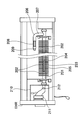
- An electric heater unit box includes an air separation pressure tank 2, a circulation pump 3, a pipe heater 4 in a square cylindrical heater unit box 1 that can be opened and closed by lids 1D and 1U at both ends as shown in FIG. Are connected by pipes via ball valves 6A, 6B, 6C and cheeses 7 and 7A to store the hot water circulation function and connect to a hot water circulation radiator for indoor heating.
- the connection port of the forward pipe (supply pipe) and the return pipe (return pipe) to the radiator may be protruded from an appropriate position of the heater unit box 1.
- the circulation pump 3, pipe heater 4, ball valves 6A, 6B, 6C and cheese 7, 7A constituting the electric heater unit box are prepared as conventional products, and the air separation pressure tank 2 is the same as in the conventional example 1. Therefore, a new tank that functions as an expansion tank and an air separator is adopted, and pipes for piping may be made of conventional ethylene-propylene rubber having excellent durability, heat resistance, and solvent resistance. Moreover, the pipe heater 4 should just employ two or more SC heaters (brand name) for 1kw heat_generation
- SC heaters brand name
- the electric heater unit box of the present invention is a small-sized (standard: width 180 mm ⁇ depth 160 mm ⁇ length 590 mm) heater unit box 1 for a general-purpose type 1 kw to 3 kw.
- the radiator can be placed side by side or vertically (not shown) as shown in Fig. 1.
- the piping connection from the heater unit box 1 to the radiator can be a close connection in the same room, etc.
- the hot water circulation heating system can be provided with a configuration that assists in room heating and substantially zero (0) heat loss.
- the hot water circulation function part is a compact rectangular tube box, there is a high degree of freedom in indoor placement, and the electric heater unit box is equipped with a power terminal regardless of whether it is a new building or a renovation. Any position can be used. Therefore, for example, even in a building that adopts the hot water circulation system of Conventional Example 1 (FIG. 6), the electric heater unit box of the present invention is not allowed to leave the old piping under the floor, in the wall, and in the ceiling when renovating.
- the heat radiation part and the hot water heating circulation part are separate, workability, In addition, an indoor hot water heating system with excellent maintainability can be provided.
- the heater unit box 1 has, for example, as shown in FIGS. 2 and 3, a long L-shaped cross section having a long left side plate 1 ⁇ / b> L and a right side plate 1 ⁇ / b> R joined in a separable manner.
- the left tube 1L having an L-shaped cross section includes a rectangular tube portion 1K and upper and lower lids 1U and 1D that are detachably fitted to both ends of the rectangular tube portion 1K.
- a plurality of wire insertion holes H1 are provided at intervals, and the other side LS2 is preferably provided with air circulation holes H3 at positions corresponding to the respective wire insertion holes H1.
- the left side plate 1L attaches a support material such as a device to the inner surface
- the right side plate 1R plays the role of a lid of the rectangular tube portion 1K.
- the wire insertion hole H1 appropriately positions the connection between an electric piping box (not shown) embedded in the wall surface WL or the floor surface FL in advance and a temperature adjustment unit (not shown) housed in the heater unit box. It is a size that can be put into a human hand, and is typically an oval hole having a width of 60 mm and a height of 40 mm, and is arranged at five locations at intervals of 100 mm.
- the air circulation hole H3 dissipates the heat in the heater unit box 1 to the outside, and forms an air through channel in the heater unit box 1, and typically has a width of 20 mm and a height. It is a 40 mm oval hole.
- the operation panel 9B is disposed on the upper lid 1U.
- the operation panel 9B is provided on the right side plate 1R that performs the lid function of the rectangular tube portion 1K. Should be arranged.
- the rectangular tube portion 1K can be disassembled into a left side plate 1L and a right side plate 1R having an L-shaped cross section, and the storage device can be fixed only to the left side plate (1L).
- Maintenance in the heater unit box 1 can be easily performed by removing the right side plate 1R as the lid member of the portion 1K.
- the arrangement of the heater unit box 1 in each room is also arranged in multiple stages with the wire insertion holes H1 in series, so that the connection position with the external electric piping box can be selected, and the appearance is not impaired. Arrangement is possible.
- the heat dissipated in the heater unit box 1 helps the room heating. And an indoor heating system in which heat loss does not substantially occur.
- the heater unit box 1 includes a left side plate 1L having an L-shaped cross section that bends and extends a corner side 1A at both ends, and an end of the corner side 1A is an L-shaped anchor piece 1C.
- the abutting anchor pieces 1F to be brought into contact with the anchor pieces 1C of the left side plate 1L are arranged at both ends of the right side plate 1R having the L shape in cross section. It is preferable to arrange the screw hole H2 and screw the screw hole H2 of the upper lid 1U and the lower lid 1D with the screw hole H2 of the left side plate 1L and the right side plate 1R.
- the left side plate 1L and the right side plate 1R are typically 1.2 mm thick steel plates, and the inner surface of the left side plate 1L is itself separated from a ball valve, cheese, and air via a conventional support member.
- a conventional support member In order to attach each necessary equipment such as a pressure tank, it is preferable to arrange reinforcing rib projections 1G on the sides LS1 and LS2 and the corner side 1A of the left side plate 1L as shown in FIG.
- the heater unit box 1 can be easily assembled and separated by fitting and screwing the upper lid 1U and lower lid 1D with the left side plate 1L and the right side plate 1R, and the storage devices are attached only to the left side plate 1L. Therefore, maintenance such as inspection, repair and replacement is easy.
- the presence of the anchor piece 1C and the abutment anchor piece 1F improves the workability of attaching the right side plate 1R to be removed during maintenance to the left side plate 1L, and the anchor piece 1C and the abutment anchor piece 1F are used to reinforce the box 1. It also plays a rib function.
- the air separation pressure tank 2 disposed in the heater unit box 1 includes a lower side 2D, a front side 2F, a rear side 2B, an upper side 2T, and both side sides 2L and 2R, and the upper side 2T is It is a box shape that is continuous with the front side 2F at the front inclined side Sf and the rear side 2B at the rear inclined side Sb, and has a connection port J1 at the center in the vertical direction of the front side 2F and the center in the vertical direction of the rear side 2B.
- connection port J2 is provided in the part
- connection port J3 is provided in the rear part of the upper side 2T
- the two blades 2A and 2A 'inclined and raised rearward are formed between the two sides 2L and 2R, and the front blade 2A.
- the rear blade 2A ′ is disposed at the lower position corresponding to the rear side of the connection port J1 on the front side and at the lower position corresponding to the upper side connection port J3.
- the capacity of the air separation pressure tank 2 depends on the amount of water sealed in the circulating heating system at normal temperature (standard: 15 ° C.) and hot water (standard: 80 ° C.), and at the time of expansion.
- the positions of the connection ports J1, J2, and J3 are such that the connection port J1 and the connection port j2 are below the water level even when the heater unit box 1 is used laterally even at room temperature.
- the connection port J3 and the connection port J2 may be determined to be below the water level.
- both the lower blade 2A and the upper blade 2A ′ cause a control turbulent flow for promoting air separation. If the inclination angle is 30 °, the tank can be used vertically or horizontally. The function of generating a controlled turbulent flow that suppresses a naturally generated vortex and promotes air separation by a diversion action is generated.
- the air separation pressure tank 2 is made of plastic resin and is about 3 times stronger than the explosion occurrence strength at high pressure in the circulation system under the proposition that an air vent valve and a safety relief valve are unnecessary.
- the safety factor is typically made of a plastic resin with a thickness of 0.6 mm.
- the water volume is 0.19 L (liter) at room temperature and the system internal pressure is 0.01 MPa.
- the amount of water is 0.26 L, and the pressure in the system is 0.04 Mpa.
- the water amount is 0.28 L
- the pressure in the system is 0.01 Mpa
- the water amount is 0.34 L
- the pressure in the system is 0 at 80 ° C. .04Mpa.
- the air separation pressure tank 2 is made of a semi-transparent plastic, it can be seen from the outside, and the water entry state in the tank when water is filled in the circulation heating system can be visually confirmed. Convenient for preparation and maintenance.
- the two blades 2A and 2A ' are effective in air separation for the inflowing hot water flow into the tank 2 when used vertically or horizontally.
- the air bubbles in the water are preferably raised and separated, and the generated air in the circulation system is safely secured in the air separation pressure tank 2
- the safety separation valve in the conventional example 1 (FIG. 6) and the air separation pressure tank which does not require the arrangement of the air vent valve are provided, and the total circulation excluding the radiator in the conventional example 1 (FIG. 6)
- the system can be housed in one heater unit box 1, the heater unit box 1 can be used vertically or horizontally, and the heater unit box 1 can be downsized.
- the air separation pressure tank 2 is arranged with the front side 2F on the upper side and the rear side 2B on the lower side
- the connection port J3 of the upper side 2T is connected to the pipe heater 4 by piping
- the forward pipe S is connected to the connection port J2 of the rear side 2B
- the connection port J1 of the front side 2F is closed by the cap 2C.
- the circulation pump 3 only needs to mount and fix the gantry 11 on the lower lid 1 ⁇ / b> D serving as the bottom plate in the heater unit box 1.
- the path connection between the connection port J3 and the pipe heater 4 and between the connection port J2 and the forward pipe S may be connected by an ethylene-propylene rubber (EPDM) pipe.
- EPDM ethylene-propylene rubber
- the circulating water is at the water level of wL 1 at normal temperature and at the water level of wL 2 at 80 ° C., and the inflow water Fin from the connection port J3 is reduced. It becomes the effluent Fout from the connection port J2, and the flow velocity rapidly decreases in the tank 2, and the lower slat 2A in the tank 2 flows upward, the downward flow F2, and the upper slat 2A.
- the upward flow F3 and the downward flow F4 cause the air bubbles in the water to separate and rise to the air zone Za at the upper part of the tank closed by the cap 2C, and radiate heat from the forward pipe S of the heater unit box 1.
- Warm water that does not contain air can be circulated in the vessel 8. Therefore, even if the air separation pressure tank 2 of the present invention is used in a vertical arrangement as shown in FIG. 5 (D), the function of the hermetic expansion tank and air separator of the conventional example 1 (FIG. 6) is exhibited.
- the heater unit box 1 can be downsized.
- the upper side 2T of the air separation pressure tank 2 is arranged on the upper side, and the connection port J1 of the front side 2F is connected to the pipe heater 4 by piping. Then, it is preferable that the connection port J2 of the rear side 2B is connected to the forward pipe S by piping, and the connection port J3 of the upper side 2T is closed by the cap 2C.
- the circulation pump 3 may be placed and fixed on the one side LS ⁇ b> 1 of the left side plate 1 ⁇ / b> L serving as the bottom plate in the heater unit box 1 via the mount 11.
- connection port J1 and the pipe heater 4 and the connection port J2 and the forward gap S may be connected by an ethylene-propylene rubber tube. And since the connection port J3 of the upper side 2T is airtightly sealed with the cap 2C, the lower area of the connection port J3 of the tank 2 becomes the air region Za.
- the air separation pressure tank 2 becomes the water level of wL 1 when the circulating water is at room temperature (15 ° C.), and the water level of wL 2 at 80 ° C.
- the circulating inflow water Fin flows into the tank 2 from the connection port J1, and the inflow water whose flow velocity has rapidly decreased is divided into the upper flow F1 and the lower flow F2 by the front blades 2A, and the air bubbles in the flowing water are separated.
- the rear slat 2A ′ is also divided into the upper flow F3 and the lower flow F4, and the air bubbles generated from the flowing water are separated and raised to the air zone Za at the upper part of the tank, and become the circulating effluent Fout. It is supplied to the forward pipe S from the rear connection port J2.
- connection port J3 on the upper side 2T is closed with a cap 2C, and in the air zone Za in the upper part of the tank 2, the maximum heating and expansion pressure of the circulating water is set below the explosion critical value (standard: 1/3 explosion pressure value). Therefore, even if the air separation pressure tank 2 is used in a horizontal arrangement as shown in FIG. 5C, the function of the hermetic expansion tank and the air separator of the conventional example 1 (FIG. 6) is exhibited.
- the box 1 can be downsized.
- the heater unit box 1 has a central corner portion of the right side plate 1R formed on the inclined side 1R ', and is reinforced on both sides of the wire insertion hole H1 row on one side LS1 of the left side plate 1L. It is preferable that the rib 1G is provided in a projecting manner and the storage devices in the heater unit box 1 are attached via the inner surface of the one side LS1 of the left side plate 1L.
- devices such as the circulation pump 3, the air separation pressure tank 2, and the pipe heater 4 fix a conventional hat-shaped steel at an appropriate position on one side LS1 of the left side plate, and support materials such as angle steel from the hat-shaped steel. Take out and fix it, and attach various devices to the support.
- the reinforcing rib 1G may be arranged in a protruding form on the outer surface when the left side plate 1L is formed with a steel plate.
- the heater unit box 1 is arranged in such a manner that the one side LS1 of the left side plate having the wire insertion hole H1 is in contact with the power supply box (not shown) on the wall surface WL or the floor surface FL.
- the reinforcing rib 1G absorbs unevenness between the heater unit box 1 and the mounting surface (wall surface WL or floor surface FL) and reinforces the device mounting surface LS1.
- Various devices can be stably held by the one side LS1 of the reinforced left side plate, and the wiring of the wires from the power supply box on the mounting surface to the heater unit box 1 through the wire insertion hole H1 also causes cross-talk. It will be a short path connection.
- the opposing surface of the one side LS1 of the left side plate 1L is the right side plate 1R that functions only as an opening / closing lid, and the right side plate 1R has a curved surface 1R with a central corner as shown in FIG. Therefore, the operation panel 9B can be arranged on the curved surface 1R 'as a lid, and the design effect is also exhibited.
- the heater unit box 1 is easy to transport and mount, and has excellent design. .
- the heating circulation function part of the hot water circulation heating system is compactly housed in a rectangular box, so that one of the hot water circulation radiators HR corresponds to one, or 2 It is possible to dispose the radiator HR close to the radiator HR in the vertical form or the horizontal form, such as one for a stand, and it is possible to arrange a separate and independent heating system for each necessary part in the building. Therefore, regardless of whether the building is newly constructed or renovated, the arrangement and construction of the hot water heating system can be freely performed.
- the heater unit box 1 containing the heating unit can be disposed adjacent to the radiator HR in the living room, there is little heat release loss in the connection path of the hot water circulation from the heating unit to the radiator. Since the heat dissipated in the connection path to the radiator HR and the heater unit box 1 becomes the indoor heating heat, the room heating with substantially no heat loss is provided while being a hot water circulation heating type.
- FIG. 1 It is the perspective view which horizontally arranged the heater unit box of the present invention under the radiator. It is a housing exploded perspective view of a heater unit box, (A) is a left side plate 1L, (B) is a right side plate 1R, (C) is an upper lid, (D) is a diagram showing a lower lid, (E) is the elements on larger scale of (C) figure. It is explanatory drawing of a heater unit box, (A) is an assembly state perspective view, (B) is a BB sectional view of (A) figure, (C) is a C section sectional view of (A) figure. An enlarged view, (D) is an enlarged view of portion D in FIG. (B), and (E) is an enlarged view of portion E in FIG.
- the heater unit box 1 stores a hot water heating function including a heater, a circulation pump, etc. of an electric hot water circulation heating system, and can be arranged vertically or horizontally adjacent to a radiator.
- the main body is composed of a main body box 1 and various devices to be housed.
- FIGS. 2A and 2B are exploded perspective views of the housing 1, wherein FIG. 2A shows the left side plate 1L, FIG. 2B shows the right side plate 1R, FIG. 2C shows the upper lid 1U, and FIG. 2D shows the lower lid 1D.
- 3A is a perspective view assembled to a housing
- FIG. 3B is a cross-sectional view taken along line BB of FIG. 3A.
- the casing of the heater unit box is a 1.2 mm thick steel plate processed with a pressing die.
- the left side plate 1L and the right side plate 1R are assembled in a square tube shape, and the upper lid 1U and the lower lid 1D are fitted to both ends.
- it is a rectangular tube having a width L1 of 180 mm, a depth W1 of 160 mm, and a height h1 of 590 mm.
- the left side plate 1L is a plate material having an L-shaped cross section and fixedly housing various devices on the inner surface, and has a height h11 of 550 mm and a side width L1 (180 mm).
- five horizontally long electric wire insertion holes H1 having a length of 60 mm and a height of 40 mm are formed at equal intervals (100 mm intervals) on the upper and lower sides, and the other side LS2 serving as the depth W1 of the housing.
- five vertically long air circulation holes H3 having a width of 20 mm and a height of 40 mm are formed at positions corresponding to the wire insertion holes H1.
- a corner side 1A having a small width W11 (standard: 35 mm) is bent and extended from the ends of the one side LS1 and the other side LS2, and the end of the corner side 1A is further extended to
- the anchor piece 1C having an L-shaped section extends inwardly by a small dimension d12 (standard: 7 mm).
- the upper and lower ends of the anchor piece 1C are cut off by a small dimension d11 (standard: 10 mm).
- screw holes H2 are formed in the upper and lower ends of each corner side and the upper and lower ends of the corner portion of the left side plate 1L.
- the one side LS1 in which the wire insertion hole H1 is disposed has a storage function, so that the reinforcing ribs 1G extending vertically are small in place (standard: two locations at L11 (40 mm) from each corner). It is formed in the form of a semicircular outward projection having a dimension d15 (standard: 6 mm).
- the right side plate 1R is aligned and integrated with the left side plate 1L to form a housing.
- the right side plate 1R is a lid plate to be removed during maintenance of various functional devices arranged on the inner surface of the left side plate 1L, as shown in FIG.
- the bent corner portion between the one side RS1 and the other side RS2 of the L-shaped cross section is formed on a smooth surface as an inclined side 1R ′ having a width L10 (standard: 86 mm), and the end of the one side RS1 and As shown in FIGS.
- the end of the other side RS2 is bent inward to form a contact anchor piece 1F protruding a small dimension d12 (standard: 7 mm), Screw holes H2 are formed above and below the ends of the one side RS1 and the other side RS2.
- the upper lid 1U has the same shape as the lower lid 1D, and is fitted and locked to the upper end of the rectangular tube portion of the housing 1 formed by the left side plate 1L and the right side plate 1R. ),
- the top plate 1T has a depth W1 of 160 mm and a width L1 of 180 mm.
- a rising piece 1P having a height of h10 (20 mm) and having a right-angled bending shape is integrally provided.
- the upper lid 1U has a box lid shape with the top plate 1T and the rising piece 1P.
- a contact locking piece 1V having a protruding length d10 (10 mm) is fixed to the inner surface of the rising piece 1P.
- Screw holes H2 corresponding to the screw holes H2 of the plate 1L and the right side plate 1R are arranged.
- the lower lid 1D has the same shape as the upper lid and is symmetrical to the top lid.
- a rising piece 1P having a height h10 of 20 mm is disposed around the bottom plate 1B having the same shape as the top plate 1T.
- the contact locking piece 1V is fixed to the inner surface of the rising piece 1P in a projecting form having a height d10 (10 mm), and the screws at the lower ends of the left side plate 1L and the right side plate 1R of the contact locking piece 1V. Screw holes H2 are arranged at positions corresponding to the holes H2.
- the assembling of the casing is such that the edges of the rising pieces 1P of the lower lid 1D and the upper lid 1U collide with the upper and lower edges of the left side plate 1L and the right side plate 1R, and each contact locking piece 1V is It is only necessary to abut on the inner surfaces of the left side plate 1L and the right side plate 1R and to fix the screws.
- the housing 1 can be disassembled and assembled by screw fixing means of each rising piece 1P, the left side plate 1L and the right side plate 1R. And each steel plate which forms an outer surface can be formed in a flush manner.
- FIG. 5A is an overall perspective view of the air separation pressure tank 2
- FIG. 5B is a front view as viewed from the arrow B in FIG. 5A
- FIG. FIG. 5D is a longitudinal sectional view illustrating the air separation pressure tank 2.
- the air separation pressure tank 2 is disposed in the hot water circulation path of the heater unit box 1 and is a novel tank that does not require the expansion tank, air separator, drain valve, and safety relief valve of the conventional example 1 (FIG. 6). An embodiment of a 1 to 3 kW heating tank will be described.
- the air separation pressure tank 2 is a semi-transparent plastic resin molded product having a general wall thickness of 0.6 mm, and the structure is as shown in FIG. 5C.
- the lower part is a length (L2) of 140 mm and a height (h3). It has a box shape with a width of 55 mm and a width (W2) of 50 mm, and the upper part has a truncated pyramid shape with a width (W3) of the upper side 2T of 38 mm, a length (L3) of 70 mm, and a height (h4) of 30 mm.
- the opposing front side 2F and rear side 2B are 30 mm (d5) upward from the lower end, at the center position of the width W2, and the upper side 2T is at the center of the width W3, at a position 55 mm (L5) from the rear side 2B.
- the connection ports J1, J2 and J3 having an outer diameter of 13 mm and a wall thickness of 0.5 mm are arranged.
- connection port J1, J2, J3, two projections 2G having a width of 1 mm and a projection height of 0.5 mm are arranged at intervals of 6 mm in order to ensure attachment of the rubber pipe 5A or the rubber cap 2C.
- a front blade 2A and a rear blade 2A ′ are arranged in a passing manner between the left side 2L and the right side 2R.
- the front slat 2A has a width W5 of 35 mm, a thickness of 6 mm, and a configuration in which the rear end is inclined 30 ° upward, the front end is a distance (L6) 25 mm from the front side 2F, and the height (h5) from the lower side 2D.
- the rear blade 2A ′ has a width W6 of 30 mm and a thickness of 6 mm, and is inclined upward by 30 °, the front end is a distance (L5) 55 mm from the rear side 2B, and the lower side 2D
- the height (h6) is 35 mm and the capacity in the tank 2 is 0.5L.
- inflow water Fin flows in from the front side connection port J1 at a flow velocity of 0.885 m / s, and becomes a slow flow F2 having a flow velocity of 0.118 m / s below the front blade plate 2A, and flows above the blade plate 2A.
- F1 has a lower flow velocity than the lower flow F2, water and air are separated, and the air reaches the upper air zone Za.
- the unseparated air at the front blade 2A has a low flow F4 of 0.06 m / s below the rear blade 2A ', and the circulating water is two blades 2A, 2A'.
- the air in the circulating water is completely separated by stirring by diverting to low-speed flow of F1, F2, F3, and F3.
- the water level of the circulating water expanded at a high temperature (80 ° C.) reaches wL 2 , and the upper side connection port J3 is closed with the rubber cap 2C, so that the air region Za becomes pressure air under the allowable pressure. .
- the tank 2 When the tank 2 is used vertically, as shown in FIG. 5D, the tank 2 is disposed with the front side 2F facing upward, and the inflow water Fin flows in from the connection port J3 on the upper side 2T, and the connection port J2 on the rear side 2B.
- the water level at the normal temperature, that is, at the start of operation is wL 1 and the tank 2 having an internal capacity of 0.5 L has a water capacity of 0.19 L and a space volume (air volume) of 0.31 L, and is heated. When the heating temperature reaches 80 ° C., the water level reaches wL 2 .
- the inflowing water Fin of 0.885 m / s abruptly decreases in flow velocity in the tank 2 and hits the rear blade 2A ′, and the flow F1 that is guided upward to the blade 2A ′ is the front blade 2A.
- the surface flow F3 and the backflow F4 are separated into the lower flow F2 and the agitated divided flow at a low flow rate, and the separated air becomes the pressure air in the air zone Za (standard: 0.04 Mpa or less). .
- what is necessary is just to use two tanks 2 together as needed, when heating capacity is set to 3 kW and reduction of the pressure in a system is aimed at.
- the circulation pump 3 may be a conventional pump that can be disposed in the heater unit box 1 on the lower lid 1D when used vertically and on the one side LS1 of the left side plate 1L when used horizontally.
- a conventional resin electromagnetic pump Uses a conventional resin electromagnetic pump.
- Resin electromagnetic pump is inexpensive, lightweight, has good transport and installation workability, and quiet noise of 38db, manufactured by Three Phase Electric Co., Ltd., product number PMD-141B (for single phase 100V), or product The number PMD-142BSG (for single phase 200V) may be employed.
- the pipe heater 4 is an SC heater manufactured by Thermal Engineering Co., Ltd., which is an energy-saving type having a high power density of 30 w / cm 2 and a thermal efficiency of 95% by thermally spraying an insulating layer, a conductive layer, and a heat insulating insulating layer on a stainless pipe. (Product name) may be adopted.
- Each pipe heater 4 of 1 kw has a pipe shape with an outer diameter of 15.88 mm, a length of 280 mm and a wall thickness of 2 mm, and the outer periphery of both ends is roughened by sandblasting, and the heating capacity If it is 3 kw, three may be employed. Then, if the heat insulating material having a thickness of 20 mm is coated on the outer periphery of the pipe, the heat generation effect is improved.
- the pipe for piping forms a flowing water path in the heater unit box 1 and has excellent durability, heat resistance, cold resistance, solvent resistance, light weight and flexibility, and a conventional thickness of 3 mm. And an ethylene-propylene rubber (EPDM) rubber pipe with an inner diameter of 14 mm is adopted.
- EPDM ethylene-propylene rubber
- Ball valves 6A, 6B, 6C are water path opening / closing valves arranged in the heater unit box 1.
- the opening / closing valve has a 3mm diameter opening / closing hole in the cylindrical part, and a hexagon wrench is inserted into the hole.
- a Zalho ball valve from Valofick (Denmark) which has a pipe shape of 29.5 mm in length and has a threaded part with a diameter of 12 mm at one end, is adopted.
- Cheese 7 and 7A are used for connecting the water path in the heater unit box 1 and are T-shaped joint fittings that can connect pipes from three sides, with a diameter of 26 mm and a length of 46 mm.
- a conventional T-type cheese 7 having a joint projecting 9 mm perpendicularly from the center in the length direction of the cylindrical portion is employed.
- the rotary joint 3F of the circulation pump 3 and the upper pipe heater 4 are connected to the piping P2, and the piping P3 and P4 are connected between the three stages of the pipe heater 4, and the lower pipe is connected.
- the heater 4 and the pressure tank 2 are connected to the pipe P5, the pipe P7 is connected from the pressure tank 2 to the hot water supply port 8S of the heat radiating section 8, and the pipe P1 is connected to the outlet 8R of the heat radiating section 8 through the cross cheese 7A.
- the control unit such as the circulation pump 3, the pipe heater 4, the thermostat (not shown), the temperature sensor (not shown), etc. is wired using the gap between the devices, and the operation panel of the electric control unit is provided.
- the pipe P ⁇ b> 8 is an example when the moisture tank 12 is employed, and the moisture tank 12 and the pipe P ⁇ b> 8 are removed when used as a normal hermetic circulation system.
- one heater unit box 1 is a radiator HR framed by an upper frame 13, a lower frame 14, a side frame 15, an upper joint 16, a lower joint 17, and a cover lid 18.
- the heater unit box 1 may be arranged 1: 1 on the side surface of the radiator HR, and one unit for the plurality of radiators HR with a wall interposed therebetween.
- a vertical type or a horizontal type may be arranged correspondingly.
- the pressure tank 2 may be used vertically as shown in FIG. 6D.
- the operation panel 9B of the electronic control unit is shown in FIG. As shown in FIG.
Landscapes
- Engineering & Computer Science (AREA)
- Physics & Mathematics (AREA)
- Thermal Sciences (AREA)
- Chemical & Material Sciences (AREA)
- Combustion & Propulsion (AREA)
- Mechanical Engineering (AREA)
- General Engineering & Computer Science (AREA)
- Steam Or Hot-Water Central Heating Systems (AREA)
- Domestic Hot-Water Supply Systems And Details Of Heating Systems (AREA)
- Housings, Intake/Discharge, And Installation Of Fluid Heaters (AREA)
- Central Heating Systems (AREA)
Priority Applications (2)
| Application Number | Priority Date | Filing Date | Title |
|---|---|---|---|
| KR1020107020990A KR101233530B1 (ko) | 2008-03-17 | 2009-03-03 | 실내 난방 방열기용의 전기히터 유닛박스 |
| CN200980109658.3A CN101978221B (zh) | 2008-03-17 | 2009-03-03 | 室内供暖散热器用的电加热器单元盒 |
Applications Claiming Priority (2)
| Application Number | Priority Date | Filing Date | Title |
|---|---|---|---|
| JP2008-067604 | 2008-03-17 | ||
| JP2008067604A JP4447040B2 (ja) | 2008-03-17 | 2008-03-17 | 室内暖房用の放熱器に接続するための電気ヒーターユニットボックス |
Publications (1)
| Publication Number | Publication Date |
|---|---|
| WO2009116386A1 true WO2009116386A1 (ja) | 2009-09-24 |
Family
ID=41090792
Family Applications (1)
| Application Number | Title | Priority Date | Filing Date |
|---|---|---|---|
| PCT/JP2009/053948 Ceased WO2009116386A1 (ja) | 2008-03-17 | 2009-03-03 | 室内暖房放熱器用の電気ヒーターユニットボックス |
Country Status (5)
| Country | Link |
|---|---|
| JP (1) | JP4447040B2 (https=) |
| KR (1) | KR101233530B1 (https=) |
| CN (1) | CN101978221B (https=) |
| RU (1) | RU2433355C1 (https=) |
| WO (1) | WO2009116386A1 (https=) |
Cited By (1)
| Publication number | Priority date | Publication date | Assignee | Title |
|---|---|---|---|---|
| CN112856557A (zh) * | 2021-03-18 | 2021-05-28 | 浙江融墨科技有限公司 | 一种感温器内嵌的整板式石墨烯制热板及其加工工艺 |
Families Citing this family (3)
| Publication number | Priority date | Publication date | Assignee | Title |
|---|---|---|---|---|
| JP4454038B2 (ja) * | 2008-04-03 | 2010-04-21 | 株式会社テスク | 電気温水循環暖房システム |
| RU191464U1 (ru) * | 2019-01-19 | 2019-08-07 | Алексей Петрович Сальников | Защитный корпус панельного обогревателя |
| CN110986154B (zh) * | 2019-12-03 | 2020-10-30 | 珠海格力电器股份有限公司 | 电暖器控制方法、装置、存储介质和电暖器 |
Citations (2)
| Publication number | Priority date | Publication date | Assignee | Title |
|---|---|---|---|---|
| JPS5818105Y2 (ja) * | 1975-08-28 | 1983-04-12 | 株式会社デンソー | 暖房装置の水回路 |
| JPH024136A (ja) * | 1988-06-21 | 1990-01-09 | Matsushita Electric Ind Co Ltd | 加熱装置 |
Family Cites Families (8)
| Publication number | Priority date | Publication date | Assignee | Title |
|---|---|---|---|---|
| CN2043726U (zh) * | 1989-01-24 | 1989-08-30 | 吕宝贞 | 电热水暖装置 |
| JPH04116321A (ja) * | 1990-09-06 | 1992-04-16 | Rinnai Corp | 温水暖房装置 |
| RU2099646C1 (ru) * | 1995-05-12 | 1997-12-20 | Акционерное Общество Открытого Типа "Новосибирский завод Химконцентратов" | Электронагреватель отопительный |
| CN2573900Y (zh) * | 2002-08-27 | 2003-09-17 | 刘淑元 | 一种新型暖气罩 |
| CZ13445U1 (cs) * | 2003-05-14 | 2003-06-30 | Korado A. S. | Otopné deskové těleso pro kombinované vytápění |
| CN2740934Y (zh) * | 2004-06-10 | 2005-11-16 | 李静 | 自动控温的家庭电暖器 |
| YU105504A (sh) * | 2004-12-02 | 2006-08-17 | Jovan Adnađ | Induktivni grejač za etažno grejanje |
| JP4454038B2 (ja) * | 2008-04-03 | 2010-04-21 | 株式会社テスク | 電気温水循環暖房システム |
-
2008
- 2008-03-17 JP JP2008067604A patent/JP4447040B2/ja not_active Expired - Fee Related
-
2009
- 2009-03-03 WO PCT/JP2009/053948 patent/WO2009116386A1/ja not_active Ceased
- 2009-03-03 CN CN200980109658.3A patent/CN101978221B/zh not_active Expired - Fee Related
- 2009-03-03 KR KR1020107020990A patent/KR101233530B1/ko not_active Expired - Fee Related
- 2009-03-03 RU RU2010142384/03A patent/RU2433355C1/ru not_active IP Right Cessation
Patent Citations (2)
| Publication number | Priority date | Publication date | Assignee | Title |
|---|---|---|---|---|
| JPS5818105Y2 (ja) * | 1975-08-28 | 1983-04-12 | 株式会社デンソー | 暖房装置の水回路 |
| JPH024136A (ja) * | 1988-06-21 | 1990-01-09 | Matsushita Electric Ind Co Ltd | 加熱装置 |
Cited By (1)
| Publication number | Priority date | Publication date | Assignee | Title |
|---|---|---|---|---|
| CN112856557A (zh) * | 2021-03-18 | 2021-05-28 | 浙江融墨科技有限公司 | 一种感温器内嵌的整板式石墨烯制热板及其加工工艺 |
Also Published As
| Publication number | Publication date |
|---|---|
| CN101978221A (zh) | 2011-02-16 |
| CN101978221B (zh) | 2013-09-11 |
| RU2433355C1 (ru) | 2011-11-10 |
| KR20100138946A (ko) | 2010-12-31 |
| JP2009222303A (ja) | 2009-10-01 |
| JP4447040B2 (ja) | 2010-04-07 |
| KR101233530B1 (ko) | 2013-02-14 |
Similar Documents
| Publication | Publication Date | Title |
|---|---|---|
| JP2009192144A (ja) | 放湿型電気温水循環暖房システム | |
| JP4454038B2 (ja) | 電気温水循環暖房システム | |
| KR101088362B1 (ko) | 시설물용 고효율 난방장치 | |
| CA2578457A1 (en) | Modular heat distribution unit for hydronic heating systems | |
| CN101688685A (zh) | 住宅用热水供给装置 | |
| JP4447040B2 (ja) | 室内暖房用の放熱器に接続するための電気ヒーターユニットボックス | |
| JP4545199B2 (ja) | 電気温水循環暖房システム | |
| JP3856324B2 (ja) | 隠蔽温水暖房システム | |
| CN102809216A (zh) | 热泵水暖装置 | |
| KR101758012B1 (ko) | 전기 온수기 겸용 온풍기 | |
| JP4916034B2 (ja) | 電気温水循環暖房システム | |
| EP2280229B1 (en) | Space Heater | |
| CN208489580U (zh) | 一种新能源发电用散热性能好的室外配电柜 | |
| JP4762298B2 (ja) | 電気温水循環床暖房システム | |
| CN104329610A (zh) | 加湿器装置 | |
| JP4882876B2 (ja) | ヒートポンプ式貯湯温水装置 | |
| CN207966668U (zh) | 一种变压器散热装置 | |
| KR102571105B1 (ko) | 핀 튜브 및 구동팬을 이용한 쿨링 모듈 장치 | |
| CN205156259U (zh) | 一种用于制冷供热的承压搪瓷水箱 | |
| JP7390182B2 (ja) | 冷蔵庫のフロア加温システム | |
| AU2024341184A1 (en) | Air source heat pump | |
| CZ2014496A3 (cs) | Otopné těleso | |
| JP2005121254A (ja) | 貯湯式給湯装置 | |
| JPH06257801A (ja) | 空調装置 |
Legal Events
| Date | Code | Title | Description |
|---|---|---|---|
| WWE | Wipo information: entry into national phase |
Ref document number: 200980109658.3 Country of ref document: CN |
|
| DPE2 | Request for preliminary examination filed before expiration of 19th month from priority date (pct application filed from 20040101) | ||
| 121 | Ep: the epo has been informed by wipo that ep was designated in this application |
Ref document number: 09723348 Country of ref document: EP Kind code of ref document: A1 |
|
| ENP | Entry into the national phase |
Ref document number: 20107020990 Country of ref document: KR Kind code of ref document: A |
|
| NENP | Non-entry into the national phase |
Ref country code: DE |
|
| WWE | Wipo information: entry into national phase |
Ref document number: 2010142384 Country of ref document: RU |
|
| 122 | Ep: pct application non-entry in european phase |
Ref document number: 09723348 Country of ref document: EP Kind code of ref document: A1 |