WO2009093342A1 - 容積流量計 - Google Patents
容積流量計 Download PDFInfo
- Publication number
- WO2009093342A1 WO2009093342A1 PCT/JP2008/054019 JP2008054019W WO2009093342A1 WO 2009093342 A1 WO2009093342 A1 WO 2009093342A1 JP 2008054019 W JP2008054019 W JP 2008054019W WO 2009093342 A1 WO2009093342 A1 WO 2009093342A1
- Authority
- WO
- WIPO (PCT)
- Prior art keywords
- pair
- positive displacement
- curve
- rotor
- circular gears
- Prior art date
- Legal status (The legal status is an assumption and is not a legal conclusion. Google has not performed a legal analysis and makes no representation as to the accuracy of the status listed.)
- Ceased
Links
Images

Classifications
-
- G—PHYSICS
- G01—MEASURING; TESTING
- G01F—MEASURING VOLUME, VOLUME FLOW, MASS FLOW OR LIQUID LEVEL; METERING BY VOLUME
- G01F3/00—Measuring the volume flow of fluids or fluent solid material wherein the fluid passes through the meter in successive and more or less isolated quantities, the meter being driven by the flow
- G01F3/02—Measuring the volume flow of fluids or fluent solid material wherein the fluid passes through the meter in successive and more or less isolated quantities, the meter being driven by the flow with measuring chambers which expand or contract during measurement
- G01F3/04—Measuring the volume flow of fluids or fluent solid material wherein the fluid passes through the meter in successive and more or less isolated quantities, the meter being driven by the flow with measuring chambers which expand or contract during measurement having rigid movable walls
- G01F3/06—Measuring the volume flow of fluids or fluent solid material wherein the fluid passes through the meter in successive and more or less isolated quantities, the meter being driven by the flow with measuring chambers which expand or contract during measurement having rigid movable walls comprising members rotating in a fluid-tight or substantially fluid-tight manner in a housing
- G01F3/10—Geared or lobed impeller meters
Definitions
- the present invention relates to a volumetric flow meter, and more particularly, to a volumetric flow meter using a pitch curve of a non-circular gear itself as a rotor tooth profile.
- the trajectory of the contact point of the external gear tooth profile that performs continuous contact is a lemniskate-type loop curve, but if this loop is flat with respect to the centerline between the axes and coincides with the centerline, the contact point is on both gears. Will move on the center of the. For this reason, the tooth profile has a contour in which a collage motion is established, which is equivalent to the pitch curve of the inconstant speed gear (non-circular gear).
- the contour of a contact wheel with a constant center distance and an angular velocity ratio that changes during rotation is a non-circular curve
- a gear that is provided with teeth as a non-circular curve is used as a pitch curve to ensure transmission. It is a non-circular gear.
- a tooth profile that can be transmitted on the pitch curve is provided.
- involute, cycloid / trochoid, novikov, or a combination thereof is used, but all have advantages and disadvantages.
- the helical gear type positive displacement meter described in Patent Document 1 uses a single-curve single-point continuous contact tooth profile.
- a one-point continuous contact tooth profile as a rotor tooth profile of a flow meter is ideal because high contact pressure strength can be expected by making the tooth surfaces contact each other unevenly, and there is no disadvantageous confinement phenomenon as a flow meter.
- a one-point continuous contact tooth profile represented by a sine curve gear has a helical shape from the relationship of the meshing rate, and if the tooth height rate is also configured by a single curve, it is 0.785 m, that is, ⁇ m / 4 (m: Module) is the limit. This is disadvantageous in terms of function and production as a flowmeter rotor.
- a pitch curve of a non-circular gear is conceivable as an ideal tooth profile curve that can be continuously contacted as a gear tooth profile and can be contacted in a rolling manner instead of a sliding contact between the tooth profiles.
- a pitch curve (corollary contact curve) of an oval gear which is a kind of non-circular gear is configured as a tooth profile of a rotor of a flow meter.
- Japanese Patent No. 3310239 Japanese Patent No. 3310239
- the torque transmission is switched at a position of the same diameter where the torque is theoretically equal.
- the tooth surfaces on the opposite side come into contact with each other, but if an appropriate gap that can be regarded as an apparent backlash can be formed there, the abnormal meshing can be reduced, and a tooth profile that makes contact with each other can be realized.
- the conventional volumetric flowmeter does not have the above technical idea of using a tooth profile having a contact contact curve as a rotor, and has not been realized so far.
- the present invention has been made in view of the above circumstances, and an object of the present invention is to provide a positive displacement flowmeter having a pair of non-circular gears that make a non-slip collage contact on a pitch line.
- a first technical means of the present invention is a volumetric flow meter in which a pair of non-circular gears are provided in a casing, and the pair of non-circular gears are in contact with a pitch line.
- r 1 ⁇ d ⁇ 1 r 2 ⁇ d ⁇ 2
- a is a similarity coefficient
- b is flatness
- n is the number of leaves
- ⁇ i (i 1, 2) Is expressed by a moving angle).
- the second technical means is characterized in that, in the first technical means, the pair of non-circular gears has a spar shape.
- the longer diameter side of one non-circular gear and the other non-circular gear when the pair of non-circular gears are in mesh with each other at the same diameter position, the longer diameter side of one non-circular gear and the other non-circular gear This is characterized in that a gap is provided between the tooth profile with the short diameter side.
- the fourth technical means is any one of the first to third technical means, wherein the pair of non-circular gears are configured by non-circular gears having the same shape.
- the number of leaves is 6 and the flatness b is 0.5.
- the number of leaves n is 8, and the flatness b is 0.34.
- the pair of non-circular gears of the positive displacement flowmeter have excellent wear resistance because of non-slip collage contact on the pitch line, and the torque efficiency can be increased because the tooth height ratio can be increased.
- the torque efficiency can be increased because the tooth height ratio can be increased.
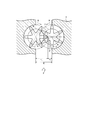
- FIG. 1 is a diagram illustrating a configuration example of a volumetric flow meter according to an embodiment of the present invention.
- 1 and 2 are a pair of rotors composed of non-circular gears
- 3 is a casing
- 4 and 5 are axial centers of the rotors 1 and 2
- 6 is a virtual pitch circle of the rotor 1
- 7 is
- 8 is a tooth tip circle of the rotor 1
- 9 is a tooth tip circle of the rotor 2.
- the pair of rotors 1 and 2 are housed in the casing 3 of the positive displacement flowmeter so as to be rotatable about the shaft centers 4 and 5.
- the rotors 1 and 2 are formed in a spar shape, and the oval pitch curve itself having the locus of the contact point P on the pitch line connecting the shafts 4 and 5 is a tooth profile curve, and satisfies the following contact condition.
- r 1 ⁇ d ⁇ 1 r 2 ⁇ d ⁇ 2
- r 1 and r 2 are moving radii, distances from the center of rotation to the oval pitch curve, and ⁇ 1 and ⁇ 2 are moving angles.
- the radial radius of the oval pitch curve which is a contact curve (closed curve), is expressed by the following formula (1), where the radial radius is r i , the similarity coefficient is a, the flatness is b, the number of leaves is n, and the dynamic angle is ⁇ i. ).
- the major axis r L and the minor axis r S are represented by the following formulas (2) and (3).
- r L a / (1-b) (2)
- r S a / (1 + b) Equation (3)
- the second interference means that the substantial parts of the tooth profile interfere with each other at a place other than the contact point P while the contact point P moves along the given locus.
- rotational torque is generated in both the rotors 1 and 2.
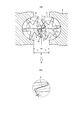
- meshing contact
- FIG. 2B is an enlarged view of an X portion in FIG.
- the torques of the rotors 1 and 2 become equal.
- the left rotor 1 is switched to the drive side.
- the pair of non-circular gears of the positive displacement flowmeter have excellent wear resistance because of non-slip colloidal contact on the pitch line, and the torque efficiency is high because the tooth height ratio can be increased.
- the torque efficiency is high because the tooth height ratio can be increased.
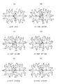
- FIG. 3A to FIG. 3F show the transition of the meshing state when the rotors 1 and 2 rotate from 0 ° to 30 °.
- P is a contact point between the rotors 1 and 2
- t is an apparent backlash between the rotors 1 and 2.
- the rotors 1 and 2 are housed in the casing 3 so as to be rotatable about the shaft centers 4 and 5, the description of the casing 3 is omitted.
- FIG. 3A shows a case where the angle ⁇ 1 of the rotor 1 is 0 ° and the angle ⁇ 2 of the rotor 2 is 0 °
- FIG. 3B shows that the angle ⁇ 1 of the rotor 1 is 10.00 °
- 2 shows a case where the angle ⁇ 2 of the rotor 2 is 20.00 °
- FIG. 3C shows a case where the angle ⁇ 1 of the rotor 1 is 15.00 ° and the angle ⁇ 2 of the rotor 2 is 23.86 °.
- FIG. 3D shows a case where the angle ⁇ 1 of the rotor 1 is 18.00 ° and the angle ⁇ 2 of the rotor 2 is 25.46 °
- FIG. 3E shows that the angle ⁇ 1 of the rotor 1 is 24
- FIG. 3F shows the case where the angle ⁇ 2 of the rotor 1 is 30.00 ° and the angle ⁇ 2 of the rotor 2 is 30.00 °. Show the case.
- the apparent backlash t is minimized, and the measured value is about 0.07 mm.
- the flatness b can be set appropriately.
- the flatness b is set to 0.34.
- the measured value of the apparent backlash t at this time is about 0.02 mm (minimum value).
- FIG. 4A to FIG. 4F show the transition of the meshing state when the rotors 1 and 2 rotate from 0 ° to 22.5 °.
- P is a contact point between the rotors 1 and 2
- t is an apparent backlash between the rotors 1 and 2.
- the rotors 1 and 2 are housed in the casing 3 so as to be rotatable about the shaft centers 4 and 5, the description of the casing 3 is omitted.
- FIG. 4A shows a case where the angle ⁇ 1 of the rotor 1 is 0 ° and the angle ⁇ 2 of the rotor 2 is 0 °
- FIG. 4B shows that the angle ⁇ 1 of the rotor 1 is 10.53 °
- 4 shows a case where the angle ⁇ 2 of the rotor 2 is 6.00 °
- FIG. 4C shows a case where the angle ⁇ 1 of the rotor 1 is 13.97 ° and the angle ⁇ 2 of the rotor 2 is 9.00 °.
- FIG. 4D shows a case where the angle ⁇ 1 of the rotor 1 is 18.53 ° and the angle ⁇ 2 of the rotor 2 is 15.00 °
- FIG. 4E shows that the angle ⁇ 1 of the rotor 1 is 20
- FIG. 4F shows the case where the angle ⁇ 1 of the rotor 1 is 22.50 ° and the angle ⁇ 2 of the rotor 2 is 22.50 °. Show the case.
- the apparent backlash t is minimized, and the measured value is about 0.02 mm.
Landscapes
- Physics & Mathematics (AREA)
- Fluid Mechanics (AREA)
- General Physics & Mathematics (AREA)
- Measuring Volume Flow (AREA)
- Rotary Pumps (AREA)
Priority Applications (4)
| Application Number | Priority Date | Filing Date | Title |
|---|---|---|---|
| CN2008801254991A CN101925803B (zh) | 2008-01-24 | 2008-03-06 | 容积流量计 |
| US12/735,276 US7870785B2 (en) | 2008-01-24 | 2008-03-06 | Positive displacement flowmeter |
| KR1020107018442A KR101190388B1 (ko) | 2008-01-24 | 2008-03-06 | 용적 유량계 |
| EP08721439A EP2241865A1 (en) | 2008-01-24 | 2008-03-06 | Positive displacement flowmeter |
Applications Claiming Priority (2)
| Application Number | Priority Date | Filing Date | Title |
|---|---|---|---|
| JP2008-013529 | 2008-01-24 | ||
| JP2008013529A JP4203531B1 (ja) | 2008-01-24 | 2008-01-24 | 容積流量計 |
Publications (1)
| Publication Number | Publication Date |
|---|---|
| WO2009093342A1 true WO2009093342A1 (ja) | 2009-07-30 |
Family
ID=40325644
Family Applications (1)
| Application Number | Title | Priority Date | Filing Date |
|---|---|---|---|
| PCT/JP2008/054019 Ceased WO2009093342A1 (ja) | 2008-01-24 | 2008-03-06 | 容積流量計 |
Country Status (7)
| Country | Link |
|---|---|
| US (1) | US7870785B2 (https=) |
| EP (1) | EP2241865A1 (https=) |
| JP (1) | JP4203531B1 (https=) |
| KR (1) | KR101190388B1 (https=) |
| CN (1) | CN101925803B (https=) |
| TW (1) | TW200933126A (https=) |
| WO (1) | WO2009093342A1 (https=) |
Families Citing this family (2)
| Publication number | Priority date | Publication date | Assignee | Title |
|---|---|---|---|---|
| JP4599454B1 (ja) * | 2009-09-07 | 2010-12-15 | 株式会社オーバル | 容積式気液二相流量計及び多相流量計測システム |
| KR102160400B1 (ko) | 2019-05-28 | 2020-10-05 | 한국생산기술연구원 | 압력 맥동 저감을 위한 용적식 수차 |
Citations (5)
| Publication number | Priority date | Publication date | Assignee | Title |
|---|---|---|---|---|
| JPS5769211A (en) * | 1980-10-17 | 1982-04-27 | Akitoshi Kitano | Flowmeter for suspension |
| JPS60166775A (ja) * | 1984-02-09 | 1985-08-30 | Kinmon Seisakusho:Kk | 非円形歯車 |
| JPS63191923A (ja) * | 1987-02-04 | 1988-08-09 | Aichi Tokei Denki Co Ltd | 流量計用回転子の製造方法 |
| JP2000346689A (ja) * | 1999-06-09 | 2000-12-15 | Oval Corp | 非円形歯車の改良及びそれを用いた非円形歯車式流量計 |
| JP3310239B2 (ja) | 1999-07-14 | 2002-08-05 | 株式会社オーバル | ヘリカルギヤ式容積流量計 |
Family Cites Families (1)
| Publication number | Priority date | Publication date | Assignee | Title |
|---|---|---|---|---|
| JPH01191019A (ja) * | 1988-01-26 | 1989-08-01 | Akitoshi Kitano | 流量計の器差補正方法 |
-
2008
- 2008-01-24 JP JP2008013529A patent/JP4203531B1/ja not_active Expired - Fee Related
- 2008-03-06 US US12/735,276 patent/US7870785B2/en not_active Expired - Fee Related
- 2008-03-06 CN CN2008801254991A patent/CN101925803B/zh not_active Expired - Fee Related
- 2008-03-06 EP EP08721439A patent/EP2241865A1/en not_active Withdrawn
- 2008-03-06 WO PCT/JP2008/054019 patent/WO2009093342A1/ja not_active Ceased
- 2008-03-06 KR KR1020107018442A patent/KR101190388B1/ko not_active Expired - Fee Related
- 2008-03-17 TW TW097109302A patent/TW200933126A/zh not_active IP Right Cessation
Patent Citations (5)
| Publication number | Priority date | Publication date | Assignee | Title |
|---|---|---|---|---|
| JPS5769211A (en) * | 1980-10-17 | 1982-04-27 | Akitoshi Kitano | Flowmeter for suspension |
| JPS60166775A (ja) * | 1984-02-09 | 1985-08-30 | Kinmon Seisakusho:Kk | 非円形歯車 |
| JPS63191923A (ja) * | 1987-02-04 | 1988-08-09 | Aichi Tokei Denki Co Ltd | 流量計用回転子の製造方法 |
| JP2000346689A (ja) * | 1999-06-09 | 2000-12-15 | Oval Corp | 非円形歯車の改良及びそれを用いた非円形歯車式流量計 |
| JP3310239B2 (ja) | 1999-07-14 | 2002-08-05 | 株式会社オーバル | ヘリカルギヤ式容積流量計 |
Also Published As
| Publication number | Publication date |
|---|---|
| EP2241865A1 (en) | 2010-10-20 |
| JP4203531B1 (ja) | 2009-01-07 |
| TW200933126A (en) | 2009-08-01 |
| TWI354095B (https=) | 2011-12-11 |
| CN101925803A (zh) | 2010-12-22 |
| KR101190388B1 (ko) | 2012-10-11 |
| KR20100101704A (ko) | 2010-09-17 |
| US20100281970A1 (en) | 2010-11-11 |
| JP2009174986A (ja) | 2009-08-06 |
| US7870785B2 (en) | 2011-01-18 |
| CN101925803B (zh) | 2012-07-04 |
Similar Documents
| Publication | Publication Date | Title |
|---|---|---|
| JP4814351B2 (ja) | 転動ボール式二段低変速装置 | |
| JP4252614B1 (ja) | 容積流量計及びヘリカル歯車 | |
| US20100234163A1 (en) | Fluctuating gear ratio limited slip differential | |
| CN116480754A (zh) | 端面圆弧与抛物线组合齿廓的抛物线齿线齿轮机构 | |
| CN202690900U (zh) | 一种新型齿形的齿轮偏心传动机构 | |
| JP4203531B1 (ja) | 容積流量計 | |
| JP6958002B2 (ja) | 内接噛合遊星歯車機構 | |
| CN104266063A (zh) | 椭圆—圆弧复合摆线转子机油泵及其转子和转子设计方法 | |
| CN110848332B (zh) | 一种相交轴非圆面齿轮传动机构 | |
| CN116498728A (zh) | 端面圆弧与抛物线组合齿廓的圆弧齿线齿轮机构 | |
| CN116592114A (zh) | 端面圆弧与渐开线组合齿廓的抛物线齿线齿轮机构 | |
| CN117006230A (zh) | 一种恒定啮合特性对构齿轮齿条副 | |
| KR101690151B1 (ko) | 나선각을 갖는 공액 이중 싸이클로이드 치형 감속기 | |
| JPS648193B2 (https=) | ||
| RU192348U1 (ru) | Эллипсно-циклоидальное зубчатое зацепление | |
| CN223469414U (zh) | 变排量齿轮泵 | |
| JPH067326Y2 (ja) | 容積流量計 | |
| CN114934985B (zh) | 一种摆线齿轮啮合副及滚针规格选取方法 | |
| CN112272738B (zh) | 具有螺旋齿的容积式齿轮机 | |
| RU2390670C1 (ru) | Циклоидальное зубчатое зацепление | |
| JP3220171U (ja) | サイクロイドピン歯車波動歯車装置 | |
| JPS63635B2 (https=) | ||
| JPH09145443A (ja) | 容積型流量計 | |
| CN107727178A (zh) | 一种容积转子流量计 | |
| JPS6359031B2 (https=) |
Legal Events
| Date | Code | Title | Description |
|---|---|---|---|
| WWE | Wipo information: entry into national phase |
Ref document number: 200880125499.1 Country of ref document: CN |
|
| 121 | Ep: the epo has been informed by wipo that ep was designated in this application |
Ref document number: 08721439 Country of ref document: EP Kind code of ref document: A1 |
|
| WWE | Wipo information: entry into national phase |
Ref document number: 12735276 Country of ref document: US |
|
| NENP | Non-entry into the national phase |
Ref country code: DE |
|
| WWE | Wipo information: entry into national phase |
Ref document number: 2008721439 Country of ref document: EP |
|
| ENP | Entry into the national phase |
Ref document number: 20107018442 Country of ref document: KR Kind code of ref document: A |