WO2009078541A1 - Method for beamforming - Google Patents
Method for beamforming Download PDFInfo
- Publication number
- WO2009078541A1 WO2009078541A1 PCT/KR2008/005099 KR2008005099W WO2009078541A1 WO 2009078541 A1 WO2009078541 A1 WO 2009078541A1 KR 2008005099 W KR2008005099 W KR 2008005099W WO 2009078541 A1 WO2009078541 A1 WO 2009078541A1
- Authority
- WO
- WIPO (PCT)
- Prior art keywords
- generating
- random variable
- optimum
- data
- codeword
- Prior art date
- Legal status (The legal status is an assumption and is not a legal conclusion. Google has not performed a legal analysis and makes no representation as to the accuracy of the status listed.)
- Ceased
Links
Classifications
-
- H—ELECTRICITY
- H04—ELECTRIC COMMUNICATION TECHNIQUE
- H04B—TRANSMISSION
- H04B7/00—Radio transmission systems, i.e. using radiation field
- H04B7/02—Diversity systems; Multi-antenna system, i.e. transmission or reception using multiple antennas
- H04B7/04—Diversity systems; Multi-antenna system, i.e. transmission or reception using multiple antennas using two or more spaced independent antennas
- H04B7/06—Diversity systems; Multi-antenna system, i.e. transmission or reception using multiple antennas using two or more spaced independent antennas at the transmitting station
- H04B7/0613—Diversity systems; Multi-antenna system, i.e. transmission or reception using multiple antennas using two or more spaced independent antennas at the transmitting station using simultaneous transmission
- H04B7/0615—Diversity systems; Multi-antenna system, i.e. transmission or reception using multiple antennas using two or more spaced independent antennas at the transmitting station using simultaneous transmission of weighted versions of same signal
- H04B7/0617—Diversity systems; Multi-antenna system, i.e. transmission or reception using multiple antennas using two or more spaced independent antennas at the transmitting station using simultaneous transmission of weighted versions of same signal for beam forming
-
- H—ELECTRICITY
- H04—ELECTRIC COMMUNICATION TECHNIQUE
- H04W—WIRELESS COMMUNICATION NETWORKS
- H04W16/00—Network planning, e.g. coverage or traffic planning tools; Network deployment, e.g. resource partitioning or cells structures
- H04W16/24—Cell structures
- H04W16/28—Cell structures using beam steering
-
- H—ELECTRICITY
- H04—ELECTRIC COMMUNICATION TECHNIQUE
- H04B—TRANSMISSION
- H04B1/00—Details of transmission systems, not covered by a single one of groups H04B3/00 - H04B13/00; Details of transmission systems not characterised by the medium used for transmission
- H04B1/76—Pilot transmitters or receivers for control of transmission or for equalising
-
- H—ELECTRICITY
- H04—ELECTRIC COMMUNICATION TECHNIQUE
- H04B—TRANSMISSION
- H04B7/00—Radio transmission systems, i.e. using radiation field
- H04B7/02—Diversity systems; Multi-antenna system, i.e. transmission or reception using multiple antennas
- H04B7/04—Diversity systems; Multi-antenna system, i.e. transmission or reception using multiple antennas using two or more spaced independent antennas
- H04B7/06—Diversity systems; Multi-antenna system, i.e. transmission or reception using multiple antennas using two or more spaced independent antennas at the transmitting station
- H04B7/0613—Diversity systems; Multi-antenna system, i.e. transmission or reception using multiple antennas using two or more spaced independent antennas at the transmitting station using simultaneous transmission
- H04B7/0615—Diversity systems; Multi-antenna system, i.e. transmission or reception using multiple antennas using two or more spaced independent antennas at the transmitting station using simultaneous transmission of weighted versions of same signal
- H04B7/0619—Diversity systems; Multi-antenna system, i.e. transmission or reception using multiple antennas using two or more spaced independent antennas at the transmitting station using simultaneous transmission of weighted versions of same signal using feedback from receiving side
- H04B7/0621—Feedback content
- H04B7/0632—Channel quality parameters, e.g. channel quality indicator [CQI]
-
- H—ELECTRICITY
- H04—ELECTRIC COMMUNICATION TECHNIQUE
- H04B—TRANSMISSION
- H04B7/00—Radio transmission systems, i.e. using radiation field
- H04B7/02—Diversity systems; Multi-antenna system, i.e. transmission or reception using multiple antennas
- H04B7/04—Diversity systems; Multi-antenna system, i.e. transmission or reception using multiple antennas using two or more spaced independent antennas
- H04B7/06—Diversity systems; Multi-antenna system, i.e. transmission or reception using multiple antennas using two or more spaced independent antennas at the transmitting station
- H04B7/0613—Diversity systems; Multi-antenna system, i.e. transmission or reception using multiple antennas using two or more spaced independent antennas at the transmitting station using simultaneous transmission
- H04B7/0615—Diversity systems; Multi-antenna system, i.e. transmission or reception using multiple antennas using two or more spaced independent antennas at the transmitting station using simultaneous transmission of weighted versions of same signal
- H04B7/0619—Diversity systems; Multi-antenna system, i.e. transmission or reception using multiple antennas using two or more spaced independent antennas at the transmitting station using simultaneous transmission of weighted versions of same signal using feedback from receiving side
- H04B7/0636—Feedback format
- H04B7/0639—Using selective indices, e.g. of a codebook, e.g. pre-distortion matrix index [PMI] or for beam selection
Definitions
- the present invention relates to a method for beamforming, and more particularly, to a method for random beamforming based on a codebook.
- Multiuser diversity is one of diversities caused by independently time-varying a channel environment between users in a wireless communication system.
- Multiuser diversity gain is obtained by allocating a resource when a channel of each user reaches the best condition through scheduling during observation of a change of a channel of each user. As the change of the channel is increased, the diversity gain is increased. Accordingly, the diversity gain is limited under a channel environment where the change of the channel is small or slow. Under the above-mentioned environment, the diversity gain is generated by inducing a large and quick change of the channel using multiple transmission antennas. This method is called opportunistic beamforming (hereinafter referred to as "OBF”) or random beamforming.
- OBF opportunistic beamforming
- OBF technology is limited to the diversity thereof under an environment corresponding to a small number of users, since it uses only one beam to search an optimal user at each time slot. Therefore, technologies that generate multibeams and select an optimal beam of each user to increase multiuser diversity gain, have been proposed in order to overcome the above-mentioned limitation.
- COBF codebook-based opportunistic beamforming
- CBF-CR codebook-based beamforming with code rotation
- the COBF uses a pilot only for channel estimation, and allows each user to estimate a channel.
- a base station receives from each user the maximum beam index and channel quality information (hereinafter referred to as "CQI") corresponding to the beam, as feedback. Then, the base station performs scheduling by allocating a user having the maximum gain to each beam thereof, and transmits data.
- CQI channel quality information
- the base station performs scheduling by allocating a user having the maximum gain to each beam thereof, and transmits data.
- a unitary matrix varying with time is multiplied by one of beam vectors in codebook, so that a beam varying with time is obtained.
- the COBF has a merit in that a pilot is fixed to a pilot used for channel estimation and a selective diversity effect is thus increased to infinity.
- the CBF-CR generates multiple codebooks by grouping large-sized codebooks and then obtains multiple beams that vary with time by diversely using the codebooks with change of time. Therefore, the same effect as the COBF method is obtained in the CBF-CR.
- the present invention has been made in an effort to provide a method for beamforming that designs a beam according to correlation between channels for a method for random beamforming based on a codebook.
- An exemplary embodiment of the present invention provides a method for beamforming of a base station.
- the method includes: generating a first random variable corresponding to a Gaussian distribution; generating a second random variable corresponding to a uniform distribution; generating a plurality of beam elements by using the first variable, the second variable, spatial correlation between channels, and indexes of transmitting antennas; and forming a beam by using the plurality of beam elements.
- Another embodiment of the present invention provides a method for beamforming of a base station.
- the method includes: generating a first random variable corresponding to a Gaussian distribution; generating a second random variable corresponding to a uniform distribution; generating a plurality of codeword elements by using the first variable, the second variable, spatial correlation between channels, and indexes of transmitting antennas; generating a codeword by using the plurality of codeword elements; and repeatedly performing the generating of the first random variable, the generating of the second random variable, the generating of the plurality of codeword elements, and the generating of the codeword, thereby generating a plurality of codewords.
- Yet another embodiment of the present invention provides a method for beamforming of a base station.
- the method includes: generating a first random variable corresponding to uniform distribution; generating a plurality of codewords by using the first random variable and indexes of transmitting antennas; generating a second random variable corresponding to a uniform distribution; generating a third random variable corresponding to a Gaussian distribution; and forming a plurality of matrices by using the second random variable, the third random variable, spatial correlation between channels, and the indexes of the transmitting antennas.
- a beam is designed according to the correlation between the channels. Therefore, it is possible to optimize the performance of the method for random beamforming that includes a COBF method and a CBF-CR method.
- FIG. 1 is a flowchart illustrating a method for beamforming according to a first exemplary embodiment of the present invention.
- FIG. 2 is a schematic block diagram of an apparatus for beamforming using a CBF-
- FIG. 3 is a flowchart illustrating a method for beamforming according to a second exemplary embodiment of the present invention.
- FIG. 4 is a schematic block diagram of an apparatus for beamforming using a COBF method according to a third exemplary embodiment of the present invention.
- FIG. 5 is a flowchart illustrating a method for beamforming according to the third exemplary embodiment of the present invention.
- FIG. 6 is a graph showing the system capacity of the related art and the method for beamforming according to an exemplary embodiment of the present invention without regard to a pilot.
- FIG. 7 is a graph showing the system capacity of the related art and the method for beamforming according to an exemplary embodiment of the present invention with regard to a pilot.
- FIG. 1 is a flowchart illustrating a method for beamforming according to a first exemplary embodiment of the present invention. A method of designing a beam for random beamforming and a method for beamforming using the beam will be described in the first exemplary embodiment of the present invention.
- a base station designs a beam (S 110).
- a method for random beamforming uses temporally different beams, and adds selective diversity for allowing a user to select one from a plurality of beams in order to supply insufficient multiuser diversities.
- Equation 1 When a single stream is transmitted instantaneously, the q-th beam at a time t is represented by Equation 1.
- w q (t) indicates the q-th beam at a time t
- M t indicates the number of antennas of a transmitting terminal.
- Equation 2 a channel at a time t is represented by Equation 2.
- h(t) indicates a channel at a time t.
- Equation 3 Equation 3
- d indicates an interval between antennas
- ⁇ indicates a wavelength
- m indicates an index of a transmitting antenna
- ⁇ ' indicates an angle of departure AoD.
- each element of the channel h(t) is modeled by Equation 4.
- CN(x,y) indicates a complex Gaussian distribution that has an average of x and a variance of y.
- the average sizes of all the channels are the same. Therefore,
- Equation 5 Equation 5
- Equation 6 Equation 6
- Equation 7 Equation 7 using Equations 5 and 6.
- Equation 8 Equation 8
- Equation 8 The base station generates Q beams instantaneously and differently by Equation 8.
- Equation 8 may be applied to any kind of beamforming using the random beamforming.
- the base station determines the optimum beam from the Q beams (S 120), multiplies data to be transmitted by the optimum beam to precode the data to be transmitted (S 130), inserts pilots into the precoded data to be transmitted, and transmits the data through a plurality of transmitting antennas (S 140).
- FIG. 2 is a schematic block diagram of an apparatus for beamforming using a CBF-
- an apparatus for beamforming for a CBF-CR method includes a receiver 210, a codeword generating and grouping unit 220, a scheduler 230, an adaptive modulator and coder (AMC) 240, a CBF-CR precoder 250, and a pilot insertion unit 260.
- AMC adaptive modulator and coder
- the receiver 210 receives feedback information from each user terminal, and transmits the feedback information to the scheduler 230, the AMC 240, and the CBF- CR precoder 250.
- the feedback information includes indexes of codewords selected by each of the users and channel quality information (CQI).
- the codeword generating and grouping unit 220 generates a plurality of codewords, and groups a plurality of codewords to generate a plurality of small codebooks.
- the scheduler 230 determines the optimum codeword and the optimum user terminal by using the feedback information of the user terminals, and the AMC 240 performs the modulation and coding of data to be transmitted.
- the CBF-CR precoder 250 multiplies the data, which is to be transmitted to the optimum user terminal, by the optimum code vector to perform precoding.
- the pilot insertion unit 260 inserts pilots into the output values of the CBF-CR precoder 250, and then transmits the output values through a plurality of transmitting antennas.
- FIG. 3 is a flowchart illustrating a method for beamforming according to a second exemplary embodiment of the present invention.
- the base station generates the codewords (S310).
- the CBF-CR generate N codebooks by grouping the plurality of codewords by Q and diversely uses the codebooks with change of time. Accordingly, the number of all the codewords is N*Q, and is represented by Equation 9.
- the base station uses TM°%w>U as the q-th beam w q (t) at a time t.
- Mod(x, y) means the remainder when x is divided by y.
- Equation 8 the m-th element of the codeword vector c n,q is modeled by Equation 10.
- the base station generates N*Q codewords instantaneously and differently by
- the base station groups the generated codewords by Q (S320) to generate N codebooks.
- the base station receives feedback from the user terminals (S330).
- the feedback include indexes q k * (t) of codewords selected by the user terminal and CQI when precoding is performed using the selected codewords.
- the base station scheduler 230 determines the optimum codeword and the optimum user terminal by using the feedback information of the user terminals (S340).
- the CBF-CR precoder 250 of the base station multiplies the d M) c , (f) data * of the optimum user terminal by the optimum codeword q ⁇ ! to precode the data of the optimum user terminal (S350).
- the pilot insertion unit 260 inserts pilots into the precoded data, and then transmits the data through a plurality of transmitting antennas (S 360).
- FIG. 4 is a schematic block diagram of an apparatus for beamforming using a COBF method according to a third exemplary embodiment of the present invention.
- a COBF apparatus includes a receiver 410, a codeword and unitary matrix generator 420, a scheduler 430, an adaptive modulator and coder (AMC) 440, a COBF precoder 450, and a pilot insertion unit 460.
- AMC adaptive modulator and coder
- the receiver 410 receives feedback information from each user terminal, and transmits the feedback information to the scheduler 430, the AMC 440, and the COBF precoder 450.
- the feedback information includes indexes q t * (t) of codewords selected by each of the users and a CQI (SINR or data rate).
- the codeword and unitary matrix generator 420 generates a plurality of codewords, and generates a plurality of unitary matrices to design a beam.
- the scheduler 430 determines the optimum codeword and the optimum user terminal by using the feedback information of the user terminals, and the AMC 440 performs the modulation and coding of data to be transmitted.
- the COBF precoder 450 multiplies the data, which is to be transmitted to the optimum user terminal, by the optimum code vector and the unitary matrix to perform precoding.
- the pilot insertion unit 460 inserts pilots into the precoded data, and then transmits the data through a plurality of transmitting antennas.
- FIG. 5 is a flowchart illustrating a method for beamforming according to the third exemplary embodiment of the present invention.
- the base station generates codewords and unitary matrices (S510).
- Equation 8 is applied to the COBF method, U n and c q may be determined by various methods. However, herein, it is difficult to design a beam so that a phase part of the beam has the optimum distribution. However, as an interval between the transmitting antennas is increased, the optimum distribution of the phase part becomes uniform. Therefore, the matrix U n and the codeword vector c q are designed using Equation 11.
- Equation 12 Equation 12
- Equation 13 Equation 13
- Equation 14 a probability density function (pdf) of " * '" is represented by Equation 14. Therefore, it is possible to obtain a Ricean distribution that is a distribution of an envelope of the optimum w m,q (t). [103] (Equation 14)
- an existing U n is a unitary matrix but the proposed U n is a non-unitary matrix.
- the reason to design a beam in a unitary matrix is to maintain transmission electric power.
- a non-unitary matrix has been used in the above-mentioned design, but transmission electric power is not increased on average due to the design of the codeword.
- the base station receives feedback from the user terminals (S520).
- the feedback include indexes q t * (t) of codewords selected by the user terminal and CQI when precoding is performed using the selected codewords.
- the base station scheduler 430 determines the optimum codeword and the optimum user terminal by using the feedback information of the user terminals (S540).
- the COBF precoder 450 of the base station multiplies the data * of the optimum user terminal by the optimum codeword * w and the unitary matrix U n to precode the data of the optimum user terminal
- the pilot insertion unit 460 inserts pilots into the precoded data, and then transmits the data through a plurality of transmitting antennas (S550).
- S550 transmits the data through a plurality of transmitting antennas.
- FIG. 6 is a graph showing the system capacity of the related art and the method for beamforming according to an exemplary embodiment of the present invention without regard to a pilot
- FIG. 7 is a graph showing the system capacity of the related art and the method for beamforming according to an exemplary embodiment of the present invention with regard to a pilot.
- a line represented as Fixed Beamforming is a line of a system that uses a fixed codebook
- a line represented as Quantized Codebook is a line of a system that uses only one codebook without code rotation in the CBF-CR method according to the second exemplary embodiment of the present invention.
- a line represented as MOBF is a line of MOBF where a beam is designed in an existing i.i.d. Gaussian form
- a line represented as MOBF (coherent beam) is a line of MOBF where a beam is designed in the form of a coherent beam
- a line represented as MOBF (adaptive) is a line of MOBF where a beam is designed using the method of designing a beam according to the first exemplary embodiment of the present invention.
- the beam of the MOBF (adaptive) has the i.i.d. Gaussian form when the spatial correlation is very low, and has the form of the coherent beam when the spatial correlation is very high. Therefore, it can be seen that the graph of the MOBF (adaptive) is similar to the graph of the MOBF (coherent beam) when a Kapa factor is small, and the graph of the MOBF (adaptive) is similar to the graph of the MOBF (i.i.d. Gaussian) when a Kapa factor is large.
- a line represented as CBF-CR is a line of CBF-CR where a beam is designed using the method of designing a beam according to the second exemplary embodiment of the present invention
- a line represented as COBF is a line of COBF where a beam is designed using the method of designing a beam according to the third exemplary embodiment of the present invention. Referring to FIGS. 6 and 7, it can be seen that the performances of the CBF-CR (adaptive) and the COBF (adaptive) are most excellent.
- the difference between the performances of the Fixed Beamforming method and the CBF-CR (adaptive) / COBF (adaptive) methods is a random beamforming effect
- the difference between the performances of the OBF method and the CBF-CR (adaptive) / COBF (adaptive) methods is a gain that is obtained by adding selective diversities of multibeams.
- the above-mentioned exemplary embodiments of the present invention are not embodied only by a method and apparatus.
- the above-mentioned exemplary embodiments may be embodied by a program performing functions, which correspond to the configuration of the exemplary embodiments of the present invention, or a recording medium on which the program is recorded.
Landscapes
- Engineering & Computer Science (AREA)
- Computer Networks & Wireless Communication (AREA)
- Signal Processing (AREA)
- Physics & Mathematics (AREA)
- Mathematical Physics (AREA)
- Radio Transmission System (AREA)
- Mobile Radio Communication Systems (AREA)
Abstract
The present invention relates to a method for random beamforming based on a codebook. The method includes generating a first random variable corresponding to a Gaussian distribution; generating a second random variable corresponding to a uniform distribution; generating a plurality of beam elements by using the first variable, the second variable, spatial correlation between channels, and indexes of transmitting antennas; and forming a beam by using the plurality of beam elements.
Description
Description
METHOD FOR BEAMFORMING
Technical Field
[1] The present invention relates to a method for beamforming, and more particularly, to a method for random beamforming based on a codebook. Background Art
[2] Multiuser diversity is one of diversities caused by independently time-varying a channel environment between users in a wireless communication system. Multiuser diversity gain is obtained by allocating a resource when a channel of each user reaches the best condition through scheduling during observation of a change of a channel of each user. As the change of the channel is increased, the diversity gain is increased. Accordingly, the diversity gain is limited under a channel environment where the change of the channel is small or slow. Under the above-mentioned environment, the diversity gain is generated by inducing a large and quick change of the channel using multiple transmission antennas. This method is called opportunistic beamforming (hereinafter referred to as "OBF") or random beamforming.
[3] OBF technology is limited to the diversity thereof under an environment corresponding to a small number of users, since it uses only one beam to search an optimal user at each time slot. Therefore, technologies that generate multibeams and select an optimal beam of each user to increase multiuser diversity gain, have been proposed in order to overcome the above-mentioned limitation. As these technologies in the related art, there are codebook-based opportunistic beamforming (hereinafter referred to as "COBF") and codebook-based beamforming with code rotation (hereinafter referred to as "CBF-CR"), where the codebook contains multiple vectors used for multibeams.
[4] The COBF uses a pilot only for channel estimation, and allows each user to estimate a channel. A base station receives from each user the maximum beam index and channel quality information (hereinafter referred to as "CQI") corresponding to the beam, as feedback. Then, the base station performs scheduling by allocating a user having the maximum gain to each beam thereof, and transmits data. In the COBF method, a unitary matrix varying with time is multiplied by one of beam vectors in codebook, so that a beam varying with time is obtained. The COBF has a merit in that a pilot is fixed to a pilot used for channel estimation and a selective diversity effect is thus increased to infinity.
[5] The CBF-CR generates multiple codebooks by grouping large-sized codebooks and then obtains multiple beams that vary with time by diversely using the codebooks with
change of time. Therefore, the same effect as the COBF method is obtained in the CBF-CR.
[6] In the COBF, multibeams have been obtained by multiplying unitary matrices, which vary with time, by beam vectors of one codebook. In contrast, in the CBF-CR, multibeams are obtained by generating multiple codebooks, and then using the codebook while exchanging the codebook with time.
[7] However, the method of designing a beam and the method of designing a beam parameter in the related art have a problem in that performance deteriorates.
[8] The above information disclosed in this Background section is only for enhancement of understanding of the background of the invention and therefore it may contain information that does not form the prior art that is already known in this country to a person of ordinary skill in the art. Disclosure of Invention Technical Problem
[9] The present invention has been made in an effort to provide a method for beamforming that designs a beam according to correlation between channels for a method for random beamforming based on a codebook. Technical Solution
[10] An exemplary embodiment of the present invention provides a method for beamforming of a base station. The method includes: generating a first random variable corresponding to a Gaussian distribution; generating a second random variable corresponding to a uniform distribution; generating a plurality of beam elements by using the first variable, the second variable, spatial correlation between channels, and indexes of transmitting antennas; and forming a beam by using the plurality of beam elements.
[11] Another embodiment of the present invention provides a method for beamforming of a base station. The method includes: generating a first random variable corresponding to a Gaussian distribution; generating a second random variable corresponding to a uniform distribution; generating a plurality of codeword elements by using the first variable, the second variable, spatial correlation between channels, and indexes of transmitting antennas; generating a codeword by using the plurality of codeword elements; and repeatedly performing the generating of the first random variable, the generating of the second random variable, the generating of the plurality of codeword elements, and the generating of the codeword, thereby generating a plurality of codewords.
[12] Yet another embodiment of the present invention provides a method for beamforming of a base station. The method includes: generating a first random
variable corresponding to uniform distribution; generating a plurality of codewords by using the first random variable and indexes of transmitting antennas; generating a second random variable corresponding to a uniform distribution; generating a third random variable corresponding to a Gaussian distribution; and forming a plurality of matrices by using the second random variable, the third random variable, spatial correlation between channels, and the indexes of the transmitting antennas.
Advantageous Effects
[13] As described above, according to the present invention, a beam is designed according to the correlation between the channels. Therefore, it is possible to optimize the performance of the method for random beamforming that includes a COBF method and a CBF-CR method.
Brief Description of the Drawings
[14] FIG. 1 is a flowchart illustrating a method for beamforming according to a first exemplary embodiment of the present invention. [15] FIG. 2 is a schematic block diagram of an apparatus for beamforming using a CBF-
CR method according to a second exemplary embodiment of the present invention. [16] FIG. 3 is a flowchart illustrating a method for beamforming according to a second exemplary embodiment of the present invention. [17] FIG. 4 is a schematic block diagram of an apparatus for beamforming using a COBF method according to a third exemplary embodiment of the present invention. [18] FIG. 5 is a flowchart illustrating a method for beamforming according to the third exemplary embodiment of the present invention. [19] FIG. 6 is a graph showing the system capacity of the related art and the method for beamforming according to an exemplary embodiment of the present invention without regard to a pilot. [20] FIG. 7 is a graph showing the system capacity of the related art and the method for beamforming according to an exemplary embodiment of the present invention with regard to a pilot.
Mode for the Invention [21] In the following detailed description, only certain exemplary embodiments of the present invention have been shown and described, simply by way of illustration. As those skilled in the art would realize, the described embodiments may be modified in various different ways, all without departing from the spirit or scope of the present invention. Accordingly, the drawings and description are to be regarded as illustrative in nature and not restrictive. Like reference numerals designate like elements throughout the specification. [22] It will be further understood that the terms "comprise" and/or "comprising," when
used in this specification, specify the presence of stated features, integers, steps, operations, elements, and/or components, but do not preclude the presence or addition of one or more other features, integers, steps, operations, elements, components, and/or groups thereof. In addition, the terms "-er", "-or", and "module" described in the specification mean units for processing at least one function and operation and can be implemented by hardware components or software components and combinations thereof.
[23] First, a method of designing a beam according to a first exemplary embodiment of the present invention and a method for beamforming using the beam will be described in detail with reference to FIG. 1. FIG. 1 is a flowchart illustrating a method for beamforming according to a first exemplary embodiment of the present invention. A method of designing a beam for random beamforming and a method for beamforming using the beam will be described in the first exemplary embodiment of the present invention.
[24] First, a base station designs a beam (S 110).
[25] A method for random beamforming uses temporally different beams, and adds selective diversity for allowing a user to select one from a plurality of beams in order to supply insufficient multiuser diversities.
[26] When a single stream is transmitted instantaneously, the q-th beam at a time t is represented by Equation 1.
[27] (Equation 1)

[29] Here, wq(t) indicates the q-th beam at a time t, and Mt indicates the number of antennas of a transmitting terminal.
[30] Further, a channel at a time t is represented by Equation 2.
[31] (Equation 2)

[33] Here, h(t) indicates a channel at a time t.
[34] When the spatial correlation between channels is very high and a linear array is used, each element of the channel h(t) is modeled by Equation 3. [35] (Equation 3)

[37] Here, d indicates an interval between antennas, λ indicates a wavelength, m indicates an index of a transmitting antenna, and ^' indicates
an angle of departure AoD.
[39] When there is no spatial correlation between the channels, the channels have independent identically distributed (hereinafter referred to as "i.i.d.") characteristics due to countless scatters. Further, it has been generally known that the channels have an i.i.d. complex Gaussian distribution. Therefore, each element of the channel h(t) is modeled by Equation 4.
[40] (Equation 4)

[42] Here, CN(x,y) indicates a complex Gaussian distribution that has an average of x and a variance of y. [43] The average sizes of all the channels are the same. Therefore,
considering the normalized channel m m ' " m ' , if the spatial correlation is very high, each element of the normalized channel is modeled by Equation 5. [44] (Equation 5)
[45] K / uncor V (0-v = exp ( I J , (m - ^ 1) -2yπd cos φ .,(tA) I
[46] If there is no spatial correlation, each element of the normalized channel is modeled by Equation 6. [47] (Equation 6)

[49] p
If it is assumed that the spatial correlation between the channels is H in the range of 0 to 1, each element of the channel is modeled by Equation 7 using Equations 5 and 6. [50] (Equation 7) [51] , , , /_
K (0 = V1 - PKnncor (0 + ΛI P Ku cor (0
[52] A case where the spatial correlation is a linear array has been exemplified in the first exemplary embodiment of the present invention. However, even if other arrays are used, it is possible to design a beam in the same manner.
[53] In order to maximize the performance of the random beamforming, a beam should be designed so that the beam and the channel have the maximum gain, that is, perform maximum ratio combining on a scheduled user's position. In this case, the beam
becomes a conjugate matrix of the channel. Accordingly, each element of the beam is modeled by Equation 8. [54] (Equation 8)

 and an arbitrary random variable that
Φ (θ ~ c/(o,2^1 has the distribution of * v . Here, U(x,y] means that distribution is uniform in a range that is larger than x and less than y. [57] The base station generates Q beams instantaneously and differently by Equation 8.
[58]
Here, the electric power w? of a transmission beam becomes 1 on
[59] average. There are many cases where the electric power of the beam should be instantaneously maintained in some systems. In these cases, wq(t) is generated using Equation 8 and then normalized, or the elements of the beam until the Mt-l-th element are generated using Equation 8 and the Mt-th element may then be obtained by subtracting the electric power of 1st to Mt-1 th elements from 1.
[60] Equation 8 may be applied to any kind of beamforming using the random beamforming.
[61] The base station determines the optimum beam from the Q beams (S 120), multiplies data to be transmitted by the optimum beam to precode the data to be transmitted (S 130), inserts pilots into the precoded data to be transmitted, and transmits the data through a plurality of transmitting antennas (S 140).
[62] Next, a method of designing a beam according to a second exemplary embodiment of the present invention and a method and apparatus for beamforming using the beam will be described in detail with reference to FIGS. 2 and 3. A method of designing a beam for a CBF-CR method and a method and apparatus for beamforming using the beam will be described in the second exemplary embodiment of the present invention.
[63] FIG. 2 is a schematic block diagram of an apparatus for beamforming using a CBF-
CR method according to a second exemplary embodiment of the present invention.
[64] As shown in FIG. 2, an apparatus for beamforming for a CBF-CR method according to the second exemplary embodiment of the present invention includes a receiver 210, a codeword generating and grouping unit 220, a scheduler 230, an adaptive modulator and coder (AMC) 240, a CBF-CR precoder 250, and a pilot insertion unit 260.
[65] The receiver 210 receives feedback information from each user terminal, and
transmits the feedback information to the scheduler 230, the AMC 240, and the CBF- CR precoder 250. The feedback information includes indexes of codewords selected by each of the users and channel quality information (CQI).
[66] The codeword generating and grouping unit 220 generates a plurality of codewords, and groups a plurality of codewords to generate a plurality of small codebooks. The scheduler 230 determines the optimum codeword and the optimum user terminal by using the feedback information of the user terminals, and the AMC 240 performs the modulation and coding of data to be transmitted.
[67] The CBF-CR precoder 250 multiplies the data, which is to be transmitted to the optimum user terminal, by the optimum code vector to perform precoding. The pilot insertion unit 260 inserts pilots into the output values of the CBF-CR precoder 250, and then transmits the output values through a plurality of transmitting antennas.
[68] FIG. 3 is a flowchart illustrating a method for beamforming according to a second exemplary embodiment of the present invention.
[69] The base station generates the codewords (S310).
[70] The CBF-CR generate N codebooks by grouping the plurality of codewords by Q and diversely uses the codebooks with change of time. Accordingly, the number of all the codewords is N*Q, and is represented by Equation 9.
[71] (Equation 9)
[72] Cn,,, n = l, - , N, q = l, -, Q
The base station uses ™°%w>U as the q-th beam wq(t) at a time t. Mod(x, y) means the remainder when x is divided by y. W (Λ — c
Accordingly, q y β mo^t.Nh-hq is satisfied. Therefore, when Equation 8 is used, the m-th element of the codeword vector cn,q is modeled by Equation 10.
[74] (Equation 10)
 Λ
Λ
 annHd φn q ~ U(0, 2π]
[77] The base station generates N*Q codewords instantaneously and differently by
Equation 10. [78] The base station groups the generated codewords by Q (S320) to generate N codebooks. [79] The base station receives feedback from the user terminals (S330). The feedback
include indexes qk *(t) of codewords selected by the user terminal and CQI when precoding is performed using the selected codewords.
[80] The base station scheduler 230 determines the optimum codeword and the optimum user terminal by using the feedback information of the user terminals (S340). The CBF-CR precoder 250 of the base station multiplies the d M) c , (f) data * of the optimum user terminal by the optimum codeword qλ ! to precode the data of the optimum user terminal (S350).
[81] The pilot insertion unit 260 inserts pilots into the precoded data, and then transmits the data through a plurality of transmitting antennas (S 360).
[82] Next, a method of designing a beam according to a third exemplary embodiment of the present invention and a method and apparatus for beamforming using the beam will be described in detail with reference to FIGS. 4 and 5. A method of designing a beam for a COBF method and a method and apparatus for beamforming using the beam will be described in the third exemplary embodiment of the present invention.
[83] FIG. 4 is a schematic block diagram of an apparatus for beamforming using a COBF method according to a third exemplary embodiment of the present invention.
[84] As shown in FIG. 4, a COBF apparatus according to the third exemplary embodiment of the present invention includes a receiver 410, a codeword and unitary matrix generator 420, a scheduler 430, an adaptive modulator and coder (AMC) 440, a COBF precoder 450, and a pilot insertion unit 460.
[85] The receiver 410 receives feedback information from each user terminal, and transmits the feedback information to the scheduler 430, the AMC 440, and the COBF precoder 450. The feedback information includes indexes qt *(t) of codewords selected by each of the users and a CQI (SINR or data rate).
[86] The codeword and unitary matrix generator 420 generates a plurality of codewords, and generates a plurality of unitary matrices to design a beam. The scheduler 430 determines the optimum codeword and the optimum user terminal by using the feedback information of the user terminals, and the AMC 440 performs the modulation and coding of data to be transmitted.
[87] The COBF precoder 450 multiplies the data, which is to be transmitted to the optimum user terminal, by the optimum code vector and the unitary matrix to perform precoding. The pilot insertion unit 460 inserts pilots into the precoded data, and then transmits the data through a plurality of transmitting antennas.
[88] FIG. 5 is a flowchart illustrating a method for beamforming according to the third exemplary embodiment of the present invention.
[89] The base station generates codewords and unitary matrices (S510).
[90] Among beams of a COBF method, the q-th beam U(t)cq at a time t is generated by multiplying Q codewords cq=[cq{ 1 }, cq{2},... cq{MJ] (q=l, 2, ...Q) by a random unitary matrix U(t) of a predetermined pattern. Since U(t) should be known at transmitting/receiving terminals, N unitary matrices are actually generated and repeatedly used. If it is assumed that the n-th unitary matrix is Un, U(t)cq becomes the form of Umod(t,N)+1cq.
[91] The beam of the COBF method is in the form of wq(t)=Umod(t>N)+iCq. Accordingly, if
Equation 8 is applied to the COBF method, Un and cq may be determined by various methods. However, herein, it is difficult to design a beam so that a phase part of the beam has the optimum distribution. However, as an interval between the transmitting antennas is increased, the optimum distribution of the phase part becomes uniform. Therefore, the matrix Un and the codeword vector cq are designed using Equation 11.
[92] (Equation 11)
[93]

[94] Here, there are Q phases, and each element of a vector Vn is represented by Equation 12.
[95] (Equation 12)

[97] Here, there are N phases and N phases.
[98] If the matrix Un and the codeword vector cq are designed as described above, the m- th element of the beam Uncq is represented by Equation 13. [99] (Equation 13)
exp ' (V 7- (vm -l) ' (K£H ~ + / • ? i, )J ), zH exp( / (m -l)/?J

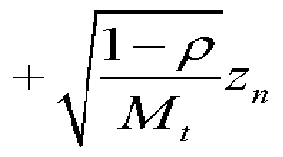
[101] In this case, since the phase distribution of Zn is uniform, the distribution z exp(j (m -l)β ) of * v ' becomes CN (0, 1) like Zn. Accordingly, according to a
[102]
comparison with Equation 8, only a phase part of a correlated part is changed to
be uniform, and a probability density function (pdf) of " * '" is represented by Equation 14. Therefore, it is possible to obtain a Ricean distribution that is a distribution of an envelope of the optimum wm,q(t). [103] (Equation 14)

[105] According to one noticeable characteristic, an existing Un is a unitary matrix but the proposed Un is a non-unitary matrix. The reason to design a beam in a unitary matrix is to maintain transmission electric power. However, a non-unitary matrix has been used in the above-mentioned design, but transmission electric power is not increased on average due to the design of the codeword.
[106] Even in this case, in order to make the system maintain instantaneous electric power to be constant, the normalization is forcibly performed so that the vector Vn of the matrix Un has electric power Mt or only the last element of the beam needs to be generated to have electric power that is obtained by subtracting the former electric power from the electric power Mt.
[107] According to another characteristic, since the design of the proposed Un is a diagonal matrix, the number of parameters to be stored is small. Therefore, if the above- mentioned design is used, (N+Q)Mt complex numbers should be stored in the case of the COBF, and N*Q*Mt complex numbers should be stored in the case of the CBF- CR. For this reason, the COBF is advantageous in terms of required memory.
[108] The base station receives feedback from the user terminals (S520). The feedback include indexes qt *(t) of codewords selected by the user terminal and CQI when precoding is performed using the selected codewords.
[109] The base station scheduler 430 determines the optimum codeword and the optimum user terminal by using the feedback information of the user terminals (S540). The COBF precoder 450 of the base station multiplies the data * of the optimum user terminal by the optimum codeword *w and the unitary matrix Un to precode the data of the optimum user terminal
(S540).
[110] The pilot insertion unit 460 inserts pilots into the precoded data, and then transmits the data through a plurality of transmitting antennas (S550).
[111] Hereinafter, the performance of the method for beamforming according to an exemplary embodiment of the present invention will be compared with the performance of the related art. FIG. 6 is a graph showing the system capacity of the related art and the method for beamforming according to an exemplary embodiment of the present invention without regard to a pilot, and FIG. 7 is a graph showing the system capacity of the related art and the method for beamforming according to an exemplary embodiment of the present invention with regard to a pilot.
[112] In a simulation where the method for beamforming according to the exemplary embodiment of the present invention is compared with the related art, it was assumed that a channel was generated to be a Kapa factor model and to have a terminal speed of 1 km/h. The channel gains of users were set to be the same on average, and generally- used instantaneous electric power constraints were used. Further, it was assumed that a ratio of one pilot in one time slot was 3.7% and the maximum number of pilots required in the COBF and CBF-CR methods was as many as the number of transmitting antennas per time slot. A 3 bit codebook (Q=8) was used as a codebook, and it was assumed that the number of users was 10 and the number of transmitting antennas was 4.
[113] In FIGS. 6 and 7, a line represented as Fixed Beamforming is a line of a system that uses a fixed codebook, and a line represented as Quantized Codebook is a line of a system that uses only one codebook without code rotation in the CBF-CR method according to the second exemplary embodiment of the present invention.
[114] A line represented as MOBF (i.i.d. Gaussian) is a line of MOBF where a beam is designed in an existing i.i.d. Gaussian form, a line represented as MOBF (coherent beam) is a line of MOBF where a beam is designed in the form of a coherent beam, and a line represented as MOBF (adaptive) is a line of MOBF where a beam is designed using the method of designing a beam according to the first exemplary embodiment of the present invention. According to the comparison between the performances of the MOBF (i.i.d. Gaussian), the MOBF (coherent beam), and the MOBF (adaptive), it can be seen that the performance of the MOBF (adaptive) is always excellent. That is, the MOBF (adaptive) always has the optimum performance regardless of spatial correlation.
[115] Furthermore, the beam of the MOBF (adaptive) has the i.i.d. Gaussian form when the spatial correlation is very low, and has the form of the coherent beam when the spatial correlation is very high. Therefore, it can be seen that the graph of the MOBF (adaptive) is similar to the graph of the MOBF (coherent beam) when a Kapa factor is small, and the graph of the MOBF (adaptive) is similar to the graph of the MOBF (i.i.d. Gaussian) when a Kapa factor is large.
[116] A line represented as CBF-CR (adaptive) is a line of CBF-CR where a beam is
designed using the method of designing a beam according to the second exemplary embodiment of the present invention, and a line represented as COBF (adaptive) is a line of COBF where a beam is designed using the method of designing a beam according to the third exemplary embodiment of the present invention. Referring to FIGS. 6 and 7, it can be seen that the performances of the CBF-CR (adaptive) and the COBF (adaptive) are most excellent.
[117] When a pilot is not regarded, the performance of the MOBF (adaptive) is similar to the performances of the CBF-CR (adaptive) and the COBF (adaptive) but a pilot overhead thereof is large. Therefore, it can be seen that the performance of the MOBF (adaptive) is low when a pilot is regarded.
[118] The difference between the performances of the Fixed Beamforming method and the CBF-CR (adaptive) / COBF (adaptive) methods is a random beamforming effect, and the difference between the performances of the OBF method and the CBF-CR (adaptive) / COBF (adaptive) methods is a gain that is obtained by adding selective diversities of multibeams.
[119] Since the random beamforming effect and the effect of the selective diversity addition are very large in the results of the simulation, it can be seen that the performances of the COBF and CBF-CR methods are excellent.
[120] The above-mentioned exemplary embodiments of the present invention are not embodied only by a method and apparatus. Alternatively, the above-mentioned exemplary embodiments may be embodied by a program performing functions, which correspond to the configuration of the exemplary embodiments of the present invention, or a recording medium on which the program is recorded. These embodiments can be easily devised from the description of the above-mentioned exemplary embodiments by those skilled in the art to which the present invention pertains.
[121] While this invention has been described in connection with what is presently considered to be practical exemplary embodiments, it is to be understood that the invention is not limited to the disclosed embodiments, but, on the contrary, is intended to cover various modifications and equivalent arrangements included within the spirit and scope of the appended claims.
Claims
[1] A method for beamforming of a base station, the method comprising: generating a first random variable corresponding to a Gaussian distribution; generating a second random variable corresponding to a uniform distribution; generating a plurality of beam elements by using the first random variable, the second random variable, spatial correlation between channels, and indexes of transmitting antennas; and forming a beam by using the plurality of beam elements.
[2] The method of claim 1, wherein a number of the beam elements is the same as that of the transmitting antennas.
[3] The method of claim 1, further comprising normalizing the plurality of beam elements.
[4] The method of claim 1, wherein one of the plurality of beam elements is generated using electric power of the rest of the beam elements except for the one of the plurality of beam elements.
[5] The method of claim 1, further comprising repeatedly performing the generating of the first random variable, the generating of the second random variable, the generating of the plurality of beam elements, and the forming of the beam, thereby forming a plurality of beams.
[6] The method of claim 5, further comprising: selecting an optimum beam from the plurality of beams; multiplying data to be transmitted by the optimum beam to precode the data to be transmitted; and inserting pilots into the precoded data to be transmitted and transmitting the data.
[7] A method for beamforming of a base station, the method comprising: generating a first random variable corresponding to a Gaussian distribution; generating a second random variable corresponding to a uniform distribution; generating a plurality of codeword elements by using the first random variable, the second random variable, spatial correlation between channels, and indexes of transmitting antennas; generating a codeword by using the plurality of codeword elements; and repeatedly performing the generating of the first random variable, the generating of the second random variable, the generating of the plurality of codeword elements, and the generating of the codeword, thereby generating a plurality of codewords.
[8] The method of claim 7, further comprising: grouping the plurality of codewords to generating a plurality of codebooks;
receiving feedback from a plurality of user terminals; determining an optimum codeword from the plurality of codewords by using the feedback, and determining an optimum user terminal from the plurality of user terminals; multiplying data, which is to be transmitted to the optimum user terminal, by the optimum codeword to precode the data to be transmitted; and inserting pilots into the precoded data to be transmitted and transmitting the data.
[9] The method of claim 8, wherein the feedback includes indexes of codewords selected by the user terminals and channel quality information when precoding is performed using the selected codewords.
[10] A method for beamforming of a base station, the method comprising: generating a first random variable corresponding to a uniform distribution; generating a plurality of codewords by using the first random variable and indexes of transmitting antennas; generating a second random variable corresponding to a uniform distribution; generating a third random variable corresponding to a Gaussian distribution; and forming a plurality of matrices by using the second random variable, the third random variable, spatial correlation between channels, and the indexes of the transmitting antennas.
[11] The method of claim 10, wherein the matrix is a diagonal matrix.
[12] The method of claim 10, further comprising: receiving feedback from the plurality of user terminals; determining an optimum codeword from the plurality of codewords by using the feedback, and determining an optimum user terminal from the plurality of user terminals; multiplying data, which is to be transmitted to the optimum user terminal, by the optimum codeword and one of the plurality of matrices to precode the data to be transmitted; and inserting pilots into the precoded data to be transmitted and transmitting the data.
Priority Applications (1)
| Application Number | Priority Date | Filing Date | Title |
|---|---|---|---|
| US12/735,143 US8687509B2 (en) | 2007-12-17 | 2008-08-29 | Method for beamforming |
Applications Claiming Priority (2)
| Application Number | Priority Date | Filing Date | Title |
|---|---|---|---|
| KR10-2007-0132624 | 2007-12-17 | ||
| KR20070132624A KR101480146B1 (en) | 2007-12-17 | 2007-12-17 | Method for beamforming |
Publications (1)
| Publication Number | Publication Date |
|---|---|
| WO2009078541A1 true WO2009078541A1 (en) | 2009-06-25 |
Family
ID=40795646
Family Applications (1)
| Application Number | Title | Priority Date | Filing Date |
|---|---|---|---|
| PCT/KR2008/005099 Ceased WO2009078541A1 (en) | 2007-12-17 | 2008-08-29 | Method for beamforming |
Country Status (3)
| Country | Link |
|---|---|
| US (1) | US8687509B2 (en) |
| KR (1) | KR101480146B1 (en) |
| WO (1) | WO2009078541A1 (en) |
Cited By (2)
| Publication number | Priority date | Publication date | Assignee | Title |
|---|---|---|---|---|
| CN102455993A (en) * | 2010-10-19 | 2012-05-16 | 泓广信息有限公司 | Statistical data analysis method |
| WO2012125931A1 (en) * | 2011-03-16 | 2012-09-20 | Interdigital Patent Holdings, Inc. | Methods for providing precoding and feedback and base station |
Families Citing this family (4)
| Publication number | Priority date | Publication date | Assignee | Title |
|---|---|---|---|---|
| KR101695716B1 (en) * | 2010-08-02 | 2017-01-13 | 삼성전자주식회사 | Scheduling method and apparatus for control average transfer rate in multiple antenna system |
| JP5540146B2 (en) | 2011-02-21 | 2014-07-02 | パナソニック株式会社 | Precoding method and precoding device |
| CN102801455B (en) * | 2012-07-31 | 2015-12-16 | 华为技术有限公司 | Wave beam method for generating codebooks, beam search method and relevant apparatus |
| CN116451517B (en) * | 2023-02-24 | 2026-04-03 | 东北大学 | Stress response assessment method for pipeline systems based on beam element and solid element coupling |
Citations (3)
| Publication number | Priority date | Publication date | Assignee | Title |
|---|---|---|---|---|
| US5634199A (en) * | 1993-04-14 | 1997-05-27 | Stanford University | Method of subspace beamforming using adaptive transmitting antennas with feedback |
| EP1259008A2 (en) * | 2001-05-17 | 2002-11-20 | SAMSUNG ELECTRONICS Co. Ltd. | Mobile communication apparatus with antenna array and mobile coomunication method therefor |
| EP1732245A2 (en) * | 2005-06-08 | 2006-12-13 | Samsung Electronics Co.,Ltd. | Transmitting and receiving apparatus and method in closed-loop mimo antenna system using codebook |
Family Cites Families (10)
| Publication number | Priority date | Publication date | Assignee | Title |
|---|---|---|---|---|
| KR100575993B1 (en) * | 2003-08-07 | 2006-05-02 | 삼성전자주식회사 | Scheduling method and apparatus for multi-user in mobile communication system using multiple transmit / receive antenna |
| JP4425925B2 (en) * | 2003-12-27 | 2010-03-03 | 韓國電子通信研究院 | MIMO-OFDM system using eigenbeamforming technique |
| KR20050120441A (en) * | 2004-06-18 | 2005-12-22 | 삼성전자주식회사 | Transmission diversity apparatus and method using multiple antenna in a mobile communication system |
| WO2006109786A1 (en) * | 2005-04-11 | 2006-10-19 | Matsushita Electric Industrial Co., Ltd. | Wireless base station device, terminal, and wireless communication method |
| KR100659725B1 (en) * | 2005-12-09 | 2006-12-19 | 한국전자통신연구원 | Transmission apparatus and method, reception apparatus and method of multi-antenna system |
| US7627347B2 (en) * | 2006-03-17 | 2009-12-01 | Nokia Corporation | Data transmission parameter optimization in MIMO communications system |
| US8095185B2 (en) * | 2006-06-09 | 2012-01-10 | Telefonaktiebolaget L M Ericsson (Publ) | Estimation of angular parameters of a signal at an antenna array |
| KR100835285B1 (en) | 2006-12-06 | 2008-06-05 | 한국전자통신연구원 | Beam forming method and beam forming apparatus therefor |
| US7769098B2 (en) * | 2007-06-05 | 2010-08-03 | Texas Instruments Incorporated | Low complexity precoding matrix selection |
| KR101358991B1 (en) | 2007-09-14 | 2014-02-06 | 삼성전자주식회사 | Method and apparatus for multiple beamforming |
-
2007
- 2007-12-17 KR KR20070132624A patent/KR101480146B1/en active Active
-
2008
- 2008-08-29 US US12/735,143 patent/US8687509B2/en active Active
- 2008-08-29 WO PCT/KR2008/005099 patent/WO2009078541A1/en not_active Ceased
Patent Citations (3)
| Publication number | Priority date | Publication date | Assignee | Title |
|---|---|---|---|---|
| US5634199A (en) * | 1993-04-14 | 1997-05-27 | Stanford University | Method of subspace beamforming using adaptive transmitting antennas with feedback |
| EP1259008A2 (en) * | 2001-05-17 | 2002-11-20 | SAMSUNG ELECTRONICS Co. Ltd. | Mobile communication apparatus with antenna array and mobile coomunication method therefor |
| EP1732245A2 (en) * | 2005-06-08 | 2006-12-13 | Samsung Electronics Co.,Ltd. | Transmitting and receiving apparatus and method in closed-loop mimo antenna system using codebook |
Cited By (2)
| Publication number | Priority date | Publication date | Assignee | Title |
|---|---|---|---|---|
| CN102455993A (en) * | 2010-10-19 | 2012-05-16 | 泓广信息有限公司 | Statistical data analysis method |
| WO2012125931A1 (en) * | 2011-03-16 | 2012-09-20 | Interdigital Patent Holdings, Inc. | Methods for providing precoding and feedback and base station |
Also Published As
| Publication number | Publication date |
|---|---|
| US20110122782A1 (en) | 2011-05-26 |
| US8687509B2 (en) | 2014-04-01 |
| KR20090065165A (en) | 2009-06-22 |
| KR101480146B1 (en) | 2015-01-07 |
Similar Documents
| Publication | Publication Date | Title |
|---|---|---|
| CN101189805B (en) | Method and device for transmitting/receiving data in mobile communication system using multiple antennas | |
| US8284855B2 (en) | Multi-user downlink linear MIMO precoding system | |
| US9444536B2 (en) | Precoding with a codebook for a wireless system | |
| KR101358991B1 (en) | Method and apparatus for multiple beamforming | |
| US8717997B2 (en) | Multi-resolution precoding codebook | |
| US20080317145A1 (en) | Multiple input multiple output communication system and a method of adaptively generating codebook | |
| US8686883B2 (en) | Codebook for multiple user multiple input multiple output system and communication device using the codebook | |
| WO2009107090A1 (en) | Limited channel information feedback error-free channel vector quantization scheme for precoding mu-mimo | |
| US8774136B2 (en) | Methods and arrangements for feeding back channel state information | |
| JP5416789B2 (en) | Data transmission method and apparatus in multiple antenna system | |
| KR20080081698A (en) | Multi-user scheduling method and apparatus in communication system | |
| EP2078443A1 (en) | Feedback apparatus, feedback method, scheduling apparatus, and scheduling method | |
| JP2010521873A (en) | Method and system for communication channel optimization in a multiple-input multiple-output (MIMO) communication system | |
| WO2010076778A1 (en) | Precoding codebooks for mimo communication systems | |
| KR100835285B1 (en) | Beam forming method and beam forming apparatus therefor | |
| US8687509B2 (en) | Method for beamforming | |
| US7907552B2 (en) | MIMO communication system with user scheduling and modified precoding based on channel vector magnitudes | |
| KR20120079926A (en) | Generation method of hybrid codebook and hybrid mu-mimo system | |
| KR20080114486A (en) | Multiple input / output communication system and communication method for adaptively generating and using codebook | |
| Sohn et al. | Downlink multiuser MIMO systems with adaptive feedback rate | |
| Kang et al. | An opportunistic beamforming technique using a quantized codebook | |
| JP2011172067A (en) | Communication control method, and base station | |
| Bose et al. | Multiuser mimo capacity with limited feedback trellis exploration based precoder | |
| Kang et al. | Codebook-based opportunistic beamforming for downlink multiple input multiple output systems | |
| Shin et al. | Average sum-rate bound of multiuser MIMO beamforming with direction-indicating matrices and channel magnitude feedback |
Legal Events
| Date | Code | Title | Description |
|---|---|---|---|
| 121 | Ep: the epo has been informed by wipo that ep was designated in this application |
Ref document number: 08793598 Country of ref document: EP Kind code of ref document: A1 |
|
| WWE | Wipo information: entry into national phase |
Ref document number: 12735143 Country of ref document: US |
|
| NENP | Non-entry into the national phase |
Ref country code: DE |
|
| 122 | Ep: pct application non-entry in european phase |
Ref document number: 08793598 Country of ref document: EP Kind code of ref document: A1 |