WO2009003157A1 - Two step process for the manufacture of hydrofluoroolefins - Google Patents
Two step process for the manufacture of hydrofluoroolefins Download PDFInfo
- Publication number
- WO2009003157A1 WO2009003157A1 PCT/US2008/068510 US2008068510W WO2009003157A1 WO 2009003157 A1 WO2009003157 A1 WO 2009003157A1 US 2008068510 W US2008068510 W US 2008068510W WO 2009003157 A1 WO2009003157 A1 WO 2009003157A1
- Authority
- WO
- WIPO (PCT)
- Prior art keywords
- catalyst
- dehydrofluorinating
- formula
- hydrochlorocarbon
- fluorinating
- Prior art date
Links
Classifications
-
- C—CHEMISTRY; METALLURGY
- C07—ORGANIC CHEMISTRY
- C07C—ACYCLIC OR CARBOCYCLIC COMPOUNDS
- C07C21/00—Acyclic unsaturated compounds containing halogen atoms
- C07C21/02—Acyclic unsaturated compounds containing halogen atoms containing carbon-to-carbon double bonds
- C07C21/18—Acyclic unsaturated compounds containing halogen atoms containing carbon-to-carbon double bonds containing fluorine
-
- C—CHEMISTRY; METALLURGY
- C07—ORGANIC CHEMISTRY
- C07C—ACYCLIC OR CARBOCYCLIC COMPOUNDS
- C07C17/00—Preparation of halogenated hydrocarbons
- C07C17/093—Preparation of halogenated hydrocarbons by replacement by halogens
- C07C17/20—Preparation of halogenated hydrocarbons by replacement by halogens of halogen atoms by other halogen atoms
- C07C17/202—Preparation of halogenated hydrocarbons by replacement by halogens of halogen atoms by other halogen atoms two or more compounds being involved in the reaction
- C07C17/206—Preparation of halogenated hydrocarbons by replacement by halogens of halogen atoms by other halogen atoms two or more compounds being involved in the reaction the other compound being HX
-
- C—CHEMISTRY; METALLURGY
- C07—ORGANIC CHEMISTRY
- C07C—ACYCLIC OR CARBOCYCLIC COMPOUNDS
- C07C17/00—Preparation of halogenated hydrocarbons
- C07C17/25—Preparation of halogenated hydrocarbons by splitting-off hydrogen halides from halogenated hydrocarbons
-
- C—CHEMISTRY; METALLURGY
- C07—ORGANIC CHEMISTRY
- C07C—ACYCLIC OR CARBOCYCLIC COMPOUNDS
- C07C17/00—Preparation of halogenated hydrocarbons
- C07C17/26—Preparation of halogenated hydrocarbons by reactions involving an increase in the number of carbon atoms in the skeleton
- C07C17/272—Preparation of halogenated hydrocarbons by reactions involving an increase in the number of carbon atoms in the skeleton by addition reactions
- C07C17/278—Preparation of halogenated hydrocarbons by reactions involving an increase in the number of carbon atoms in the skeleton by addition reactions of only halogenated hydrocarbons
Definitions
- the present invention relates to a process for the manufacture of hydrofluoroolefins. More particularly, the present invention relates to a process for manufacturing hydrofluoropropene in a two step process.
- the two step process comprises fluorination of a hydrochloropropane to hydrfluoropropane, followed by dehydrofluorination of the latter compound to form hydrofluoropropene.
- CFCs chlorofluorocarbons
- HFC hydrofluorocarbon
- ODP ozone depletion potential
- the present invention describes a process for manufacturing of hydrofluoropropenes.
- the first step of the present process comprises the catalyzed liquid phase fluorination of hydrochloropropane to hydrofluoropropane.
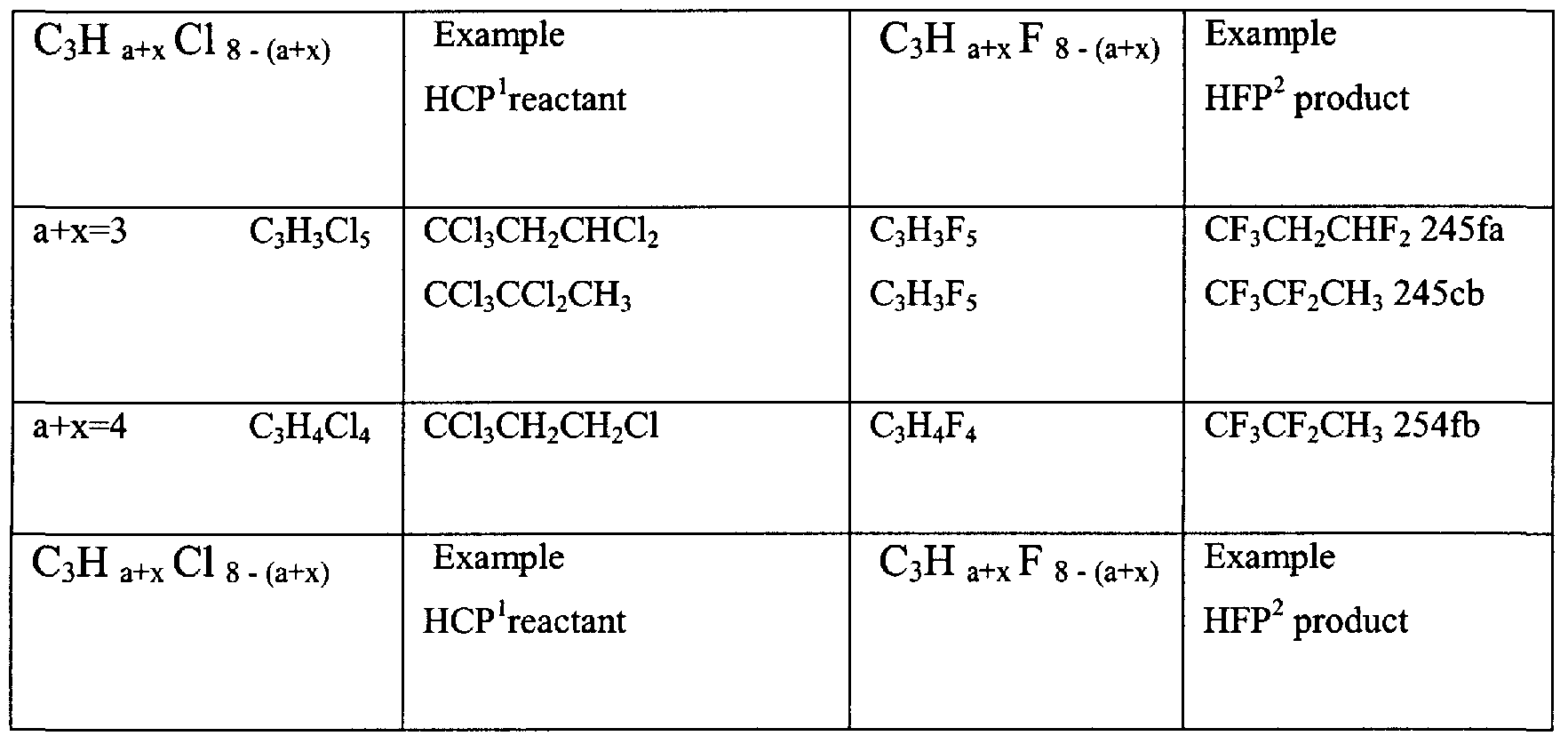
- the first step of the present invention fluorination of a hydrochloropropane (HCP) to form a hydrofluoropropane (HFP) proceeds via Formula 1.
- the first step is a liquid fluorination process using HF as a fluorinating agent and proceeds through Cl-F exchanges.
- a liquid phase fluorination process present advantages versus a gas phase fluorination process as it leads to a better selectivity towards the desired product with a much lower required energy level.
- liquid phase fluorination usually achieves partial Cl exchange and often a second step to achieve full Cl replacement is required.
- the derivatives of the metals are intended to mean the hydroxides, oxides and the organic or inorganic salts of these metals, as well as their mixtures. Those particularly adopted are the titanium, tantalum, molybdenum, boron, tin and antimony derivatives.
- the catalyst is preferably chosen from the derivatives of metals of groups 14 (IVa) and 15 (Va) of the Periodic Table of the elements, and more particularly from tin and antimony derivatives.
- the preferred derivatives of the metals are the salts and these are preferably chosen from the halides and more particularly from chlorides, fluorides and chlorofluorides.
- Particularly preferred fluorination catalysts according to the present invention are tin and antimony chlorides, fluorides and chlorofluorides, especially tin tetrachloride and antimony pentachloride. Antimony pentachloride is very particularly recommended.
- an ionic liquid derived from antimony, titanium, niobium and tantalum is suitable for liquid phase fluorination processes.
- a description of the preparation of these catalysts is disclosed in the US Patent No. 6,881,698 incorporated herein by reference.
- the catalyst is selected from metal fluorides and chlorofluorides
- these can be obtained from a chloride which is subjected to an at least partial fluorination.
- This fluorination may, for example, be carried out by means of hydrogen fluoride, before the catalyst is brought into contact with the hydrochloropropane. hi an alternative form, it may be carried out in situ, during the reaction of the hydrochloropropane with hydrogen fluoride.
- the quantity of catalyst used can vary within wide limits. It is generally at least 0.001 mole of catalyst per mole of the hydrochlorocarbon. It is preferably at least 0.01 mole of catalyst per mole of the hydrochloropropane. In principle there is no upper limit to the quantity of catalyst used.
- the molar ratio of the catalyst to the hydrochloropropane may reach 1000. In practice, however, at most approximately 5 moles of catalyst are generally employed per mole of the hydrochloropropane. Approximately 1 mole is preferably not exceeded. In a particularly preferred manner, approximately 0.5 moles of catalyst per mole of the hydrochloropropane are generally not exceeded.
- the molar ratio of hydrogen fluoride to the hydrochloropropane used is generally at least 5.
- the work is preferably done with a molar ratio of at least 8.
- the molar ratio of hydrogen fluoride to the hydrochloropropane used generally should not exceed 100 and preferably does not exceed 50.
- the temperature at which the hydrofluorination is performed is generally at least 50° C and is preferably at least 80° C.
- the temperature generally should not exceed 150° C and preferably does not exceed 130° C.
- antimony pentachloride as the catalyst, good results are obtained at a temperature of about 100 to 120°C.
- the activation process is carried out prior to admitting the reactants to the reaction vessel.
- the first step of the process according to the present invention is carried out in liquid phase.
- the pressure is chosen so as to keep the reaction mixture in liquid form.
- the pressure used varies as a function of the temperature of the reaction mixture. It is generally from 2 bar to 40 bar.
- the work is preferably carried out at a temperature and pressure at which, furthermore, the hydro fluoropropane produced is at least partially in gaseous form, which enables it to be easily isolated from the reaction mixture.
- the process according to the invention may be carried out continuously or batch wise. It is to be understood that, in a noncontinuous process, the quantity of catalyst used is expressed in relation to the initial quantity of the hydrochloropropane used and, in a continuous process, in relation to the stationary quantity of the hydrochloropropane present in the liquid phase.
- the residence time of the reactants in the reactor must be sufficient for the reaction of the hydrochloropropane with hydrogen fluoride to take place with an acceptable yield. It can easily be determined as a function of the operating conditions adopted.
- the processes according to the invention must be carried out in a corrosion resistant reactor, such as one coated with a fluorpolymer resistant to both HF and the catalyst. It is advantageous to separate the hydrofluoropropane and the hydrogen chloride from the reaction mixture as they are being formed and to keep in, or return to, the reactor the unconverted reactants, as well as any hydrochlorofiuoropropanes possibly formed by incomplete fluorination of the feed stock hydrochloropropane.
- the process according to the invention is advantageously carried out in a reactor equipped with a device for drawing off a gas stream, this device consisting, for example, of a distillation column and a reflux condenser mounted above the reactor.
- this device makes it possible to draw off in vapor phase the hydrofluoropropane and hydrogen chloride which are produced while keeping in the reactor, in the liquid state, the unconverted hydrochloropropane and most of the hydrogen fluoride, as well as, where appropriate, most of the co-products resulting from partial fluorination of the hydrochloropropane.
- the second step, dehydro fluorination of the hydrofluoropropane produced in the first step is carried out in the vapor phase.
- Vapor phase dehydro fluorination of the hydrofluoropropane may be carried out using typical dehydrofluorination catalysts.
- the present dehydrofluorination may be carried out using any dehydrofluorination catalyst known in the art.
- These catalysts include, but are not limited to, aluminum fluoride; fluorided alumina; metals on aluminum fluoride; metals on fluorided alumina; oxides, fluorides, and oxyfluorides of magnesium, zinc and mixtures of magnesium and zinc and/or aluminum; lanthanum oxide and fluorided lanthanum oxide; chromium oxides, fluorided chromium oxides, and cubic chromium trifluoride; carbon, acid-washed carbon, activated carbon, three dimensional matrix carbonaceous materials; and metal compounds supported on carbon.
- the metal compounds are oxides, fluorides, and oxyfluorides of at least one metal selected from the group consisting of sodium, potassium, rubidium, cesium, yttrium, lanthanum, cerium, praseodymium, neodymium, samarium, chromium, iron, cobalt, rhodium, nickel, copper, zinc, and mixtures thereof.
- the second step of the present invention the dehydrofluorination of the hydrofluoropropane to form a hydrofluoroolef ⁇ ne HFO proceeds via Formula 2 C 3 H a+x F 8- (a+x) -» C 3 H (a+x-1) F 7-(a+x) + HF Formula 2
- Dehydrofluorination catalysts include aluminum fluoride, fluorided alumina, metals on aluminum fluoride, and metals on fluorided alumina, as disclosed in EP 406748 B 1 , incorporated herein by reference.
- Suitable metals include chromium, magnesium (e.g., magnesium fluoride), Group VIIB metals (e.g., manganese), Group IIIB metals (e.g., lanthanum), and zinc. In use, such metals are normally present as halides (e.g., fluorides), as oxides and/or as oxyhalides.
- Metals on aluminum fluoride and metals on fluorided alumina can be prepared by procedures as described in U.S.
- the total metal content of the catalyst is from about 0.1 to 20 percent by weight, typically from about 0.1 to 10 percent by weight.
- Preferred catalysts include catalysts consisting essentially of aluminum fluoride and/or fluorided alumina.
- dehydrofluorination catalysts include oxides, fluorides, and oxyfluorides of magnesium, zinc and mixtures of magnesium and zinc and/or aluminum.
- a suitable catalyst may be prepared, for example by drying magnesium oxide until essentially all water is removed, e.g., for about 18 hours at about 100° C. The dried material is then transferred to the reactor to be used. The temperature is then gradually increased to about 400° C while maintaining a flow of nitrogen through the reactor to remove any remaining traces of moisture from the magnesium oxide and the reactor.
- the temperature is then lowered to about 200° C and a fluorinating agent, such as HF, or other vaporizable fluorine containing compounds such as SF 4 , CCl 3 F, CClF 3 , CHF 3 , CHClF 2 , CF 3 CH 2 F , CF 3 CHF 2 and the like, optionally diluted with an inert gas such as nitrogen, is passed through the reactor.
- a fluorinating agent such as HF, or other vaporizable fluorine containing compounds
- SF 4 cycloxane
- CCl 3 F CClF 3 , CHF 3 , CHClF 2 , CF 3 CH 2 F , CF 3 CHF 2 and the like
- an inert gas such as nitrogen
- the temperature can be increased to about 450° C and held at that temperature to convert the magnesium oxide to a fluoride content corresponding to at least 40 percent by weight, e.g., for 15 to 300 minutes, depending on the fluoriding agent flow rate and the catalyst volume.
- the fluorides are in the form of magnesium fluoride or magnesium oxyfluoride; the remainder of the catalyst is magnesium oxide. It is understood in the art that fluoriding conditions such as time and temperature can be adjusted to provide higher than 40 percent by weight fluoride-containing material.
- the dehydrofluorination catalysts could include chromium oxides, fluorided chromium oxides, and cubic chromium trifluoride.
- Cubic chromium trifluoride may be prepared from CrF 3 XH 2 O, where X is 3 to 9, preferably 4, by heating in air or an inert atmosphere (e.g., nitrogen or argon) at a temperature of about 350° C. to about 400° C. for 3 to 12 hours, preferably 3 to 6 hours.
- Cubic chromium trifluoride is useful by itself, or together with other chromium compounds, as a dehydrofluorination catalyst. Preparation of cubic chromium trifluoride is described in U.S. Pat. No. 6,031,141, incorporated herein by reference. Of note are catalyst compositions comprising chromium wherein at least 10 weight percent of the chromium is in the form of cubic chromium trifluoride, particularly catalyst compositions wherein at least 25 percent of the chromium is in the form of cubic chromium trifluoride, and especially catalyst compositions wherein at least 60 percent of the chromium is in the form of cubic chromium trifluoride.
- the chromium, including the cubic chromium trifluoride can be supported on and/or physically mixed with materials such as carbon, aluminum fluoride, fluorided alumina, lanthanum fluoride, magnesium fluoride, calcium fluoride, zinc fluoride and the like. Preferred are combinations including cubic chromium trifluoride in combination with magnesium fluoride and/or zinc fluoride.
- dehydrofluorination catalysts include activated carbon, or three dimensional matrix carbonaceous materials as disclosed in U.S. Pat. No.
- Carbon includes acid-washed carbon (e.g., carbon which has been treated with hydrochloric acid or hydrochloric acid followed by hydrofluoric acid). Acid treatment is typically sufficient to provide carbon that contains less than 1000 ppm of ash. Suitable acid treatment of carbon is described in U.S. Pat. No. 5,136,113, incorporated herein by reference. The carbon also includes three dimensional matrix porous carbonaceous materials. Examples are those described in U.S. Pat. No. 4,978,649, incorporated herein by reference.
- three dimensional matrix carbonaceous materials which are obtained by introducing gaseous or vaporous carbon-containing compounds (e.g., hydrocarbons) into a mass of granules of a carbonaceous material (e.g., carbon black); decomposing the carbon-containing compounds to deposit carbon on the surface of the granules; and treating the resulting material with an activator gas comprising steam to provide a porous carbonaceous material.
- gaseous or vaporous carbon-containing compounds e.g., hydrocarbons
- a carbonaceous material e.g., carbon black
- the catalytic dehydrofluorination may be suitably conducted at a temperature in the range of from about 200° C. to about 500° C, and, in another embodiment, from about 300° C. to about 450° C.
- the contact time is typically from about 1 to about 450 seconds, and, in another embodiment, from about 10 to about 120 seconds.
- the reaction pressure can be subatmospheric, atmospheric or superatmostpheric. Generally, near atmospheric pressures are preferred. However, the dehydrofluorination can be beneficially run under reduced pressure (i.e., pressures less than one atmosphere).
- the catalytic dehydrofluorination can optionally be carried out in the presence of an inert gas such as nitrogen, helium, or argon.
- an inert gas such as nitrogen, helium, or argon.
- the addition of an inert gas can be used to increase the extent of dehydrofluorination.
- Nitrogen is the preferred inert gas.
- Appropriate temperatures may be between about 350° C. and about 900° C, and preferably between about 450° C and about 900° C.
- the residence time of gases in the reaction zone is typically from about 0.5 to about 60 seconds, and preferably from about 2 seconds to about 20 seconds.
- the catalytic dehydrofluorination can be carried out in the absence or presence of low levels of an oxidizer such as oxygen or an oxygen containing agent such as air or carbon dioxide.
- a low level of chlorine gas can also be used. If the process is carried out in the absence of the co-feed of an oxidizer, the dehydrofluorinating catalyst may become deactivated after usage for several hours or days. If this occurs, the process must be shut down and catalyst subjected to a regeneration cycle.
- the regeneration temperature is ideally between 300-400°C.
- a stream of air is gradually introduced into the reactor in such a way as not to exceed 375°-400°C. In case of run away reaction, process air feed must be stopped, until the reactor temperature is restored to 375°-400°C. Ideal contact time is between 1-100 seconds.
- the regeneration cycle is continuously monitored for CO 2 evolution and is concluded when no more CO 2 evolution is observed. The CO 2 evolution is most conveniently monitored by using on line GC.
- the dehydrofluorination process can be carried out using oxygen containing gas such as air or CO 2 .
- An ideal air feed is between 0.1-1% calculated as oxygen. If an active air gas is cofeed, the catalyst may be run for extended period of time without the need for regular shut down.
- Pyrolysis means chemical change produced by heating in the absence of catalyst. Pyrolysis reactors generally comprise three zones: a) a preheat zone, in which reactants are brought close to the reaction temperature; b) a reaction zone, in which reactants reach reaction temperature and are at least partially pyrolyzed, and products and any byproducts form; c) a quench zone, in which the stream exiting the reaction zone is cooled to stop the pyrolysis reaction. Laboratory- scale reactors have a reaction zone, but the preheating and quenching zones may be omitted.
- the reaction pressure for the dehydrofluorination reaction at elevated temperature in the absence of catalyst may be subatmospheric, atmospheric, or superatmospheric. Generally, near atmospheric pressures are preferred. However, the dehydrofluorination can be beneficially run under reduced pressure (i.e., pressures less than one atmosphere).
- the dehydrofluorination at an elevated temperature in the absence of a catalyst may optionally be carried out in the presence of an inert gas such as nitrogen, helium or argon.
- an inert gas such as nitrogen, helium or argon.
- the addition of an inert gas can be used to increase the extent of dehydrofluorination.
- processes where the mole ratio of inert gas to the hydrofluorocarbon undergoing dehydrofluorination is from about 5:1 to about 1:1.
- Nitrogen is the preferred inert gas.
- the reaction zone for either catalyzed or non-catalyzed dehydrofluorination may be a reaction vessel fabricated from nickel, iron, titanium or their alloys, as described in U.S. Pat. No. 6,540,933, incorporated herein by reference.
- a reaction vessel of these materials e.g., a metal tube
- alloys it is meant a nickel alloy containing from about 1 to about 99.9 weight percent nickel, an iron alloy containing about 0.2 to about 99.8 weight percent iron, and a titanium alloy containing about 72 to about 99.8 weight percent titanium.
- an empty (unpacked) reaction vessel made of nickel or alloys of nickel such as those containing about 40 weight percent to about 80 weight percent nickel, e.g., InconelTM 600 nickel alloy, HastelloyTM C617 nickel alloy or HastelloyTM C276 nickel alloy.
- the reactor may be of any shape consistent with the process but is preferably a cylindrical tube, either straight or coiled. Although not critical, such reactors typically have an inner diameter of from about 1.3 to about 5.1 cm (about 0.5 to about 2 inches) and a length from 5 to about 8 cm (about 6 to 20 inches). Heat is applied to the outside of the tube, the chemical reaction taking place on the inside of the tube.
- the reactor and its associated feed lines, effluent lines and associated units should be constructed, at least as regards the surfaces exposed to the reaction reactants and products, of materials resistant to hydrogen fluoride.
- Typical materials of construction include stainless steels, in particular of the austenitic type, the well- known high nickel alloys, such as Monel ® nickel-copper alloys, Hastelloy-based alloys and Inconel ® nickel-chromium alloys and copper clad steel.
- the reactor may be constructed of more than one material.
- the outer surface layer of the reactor should be chosen for ability to maintain structural integrity and resist corrosion at the pyrolysis temperature
- the inner surface layer of the reactor should be chosen of materials resistant to attack by, that is, inert to, the reactant and products.
- the reactor may be constructed of an outer material chosen for physical strength at high temperature and an inner material chosen for resistance to corrosion by the reactants and products under the temperature of the pyrolysis.
- the reactor inner surface layer be made of high nickel alloy, that is an alloy containing at least about 50 wt % nickel, preferably a nickel alloy having at least about 75 wt % nickel, more preferably a nickel alloy having less than about 8 wt % chromium, still more preferably a nickel alloy having at least about 98 wt % nickel, and most preferably substantially pure nickel, such as the commercial grade known as Nickel 200.
- the material for the inner surface layer of the reactor is gold.
- the thickness of the inner surface layer does not substantially affect the pyrolysis and is not critical so long as the integrity of the inner surface layer is intact.
- the thickness of the inner surface layer is typically from about 10 to about 100 mils (0.25 to 2.5 mm).
- the thickness of the inner surface layer can be determined by the method of fabrication, the cost of materials, and the desired reactor life.
- the reactor outer surface layer is resistant to oxidation or other corrosion and maintains sufficient strength at the reaction temperatures to keep the reaction vessel from failing of distorting.
- This layer is preferably Inconel ® alloy, more preferably Inconel ® 600.
- Reactors useful for carrying out the present process are tubes comprising the aforementioned materials of construction.
- Reactors include those wherein the flow of gases through the reactor is partially obstructed to cause back-mixing, i.e. turbulence, and thereby promote mixing of gases and good heat transfer.
- This partial obstruction can be conveniently obtained by placing packing within the interior of the reactor, filling its cross-section or by using perforated baffles.
- the reactor packing can be particulate or fibrillar, preferably in cartridge disposition for ease of insertion and removal, has an open structure like that of Raschig Rings or other packings with a high free volume, to avoid the accumulation of coke and to minimize pressure drop, and permits the free flow of gas.
- the exterior surface of such reactor packing comprises materials identical to those of the reactor inner surface layer, materials that do not catalyze dehydrofluorination of hydrofluorocarbons and are resistant to hydrogen fluoride.
- the free volume is the volume of the reaction zone minus the volume of the material that makes up the reactor packing.
- the free volume is at least about 80%, preferably at least about 90%, and more preferably about 95%.
- the maximum temperature is no greater than about 1,000° C, preferably no greater than about 950° C, and more preferably no greater than about 900° C.
- the pyrolysis temperature is the temperature of the gases inside at about the mid-point of the reaction zone.
- the residence time of gases in the reaction zone is typically from about 0.5 to about 60 seconds, more preferably from about 2 seconds to about 20 seconds at temperatures of from about 700° to about 900° C and atmospheric pressure. Residence time is determined from the net volume of the reaction zone and the volumetric feed rate of the gaseous feed to the reactor at a given reaction temperature and pressure, and refers to the average amount of time a volume of gas remains in the reaction zone.
- the pyrolysis is preferably carried out to a conversion of the CF 3 CH 2 CF 3 at least about 25%, more preferably to at least about 35%, and most preferably to at least about 45%.
- conversion is meant the portion of the reactant that is consumed during a single pass through the reactor.
- the reaction is preferably conducted at subatmospheric, or atmospheric total pressure. That is, the reactants plus other ingredients are at subatmospheric pressure or atmospheric pressure. If inert gases are present as other ingredients, as discussed below, the sum of the partial pressures of the reactants plus such ingredients is subatmospheric or atmospheric. Near atmospheric total pressure is more preferred.
- the reaction can be beneficially run under reduced total pressure (i.e., total pressure less than one atmosphere).
- the co-produced HF must be separated from the fluorinated propene to minimize the reverse reaction. This separation is preferably accomplished by processes known in the art such as scrubbing, adsorption or membrane separation.
- Example 1 Liquid phase fluorination of 240cb to 245cb
- a catalyst would be activated by condensing anhydrous HF gas (120 grams, 6 moles) in one liter autoclave, equipped with a 100 psig back pressure regulator, and a cold condenser maintained at 5° C and admitting anhydrous SbCl 5 (5 grams, .017 moles) to the autoclave under a dry nitrogen atmosphere.
- the co-product HCl gas would be vented to a water scrubber.
- 120 grams, .55 moles of 240cb would be added to the autoclave and the mixture stirred continuously at 100°C for 2 hours.
- the HCl gas co- product would be vented continuously, and the organic product obtained would be transferred with nitrogen flow 20ccm and collected at 0° C.
- the product obtained would be expected to be 60 grams of 245cb (CF 3 CF 2 CH 3 ). A 90% selectivity at 100% conversion would be expected.
- 245cb was fed to a fixed bed reactor containing NI 6%-Cr6% catalyst supported on AlF 3 .
- the catalyst was activated with HF gas at high temperature.
- the reactor was maintained at 350° C and the contact time was 89 seconds. A 70% conversion with 85% selectivity towards 1234yf was obtained.
- Anhydrous HF gas 120 grams, 6 moles would be condensed in one liter autoclave, equipped with a 100 psig back pressure regulator and a cold condenser maintained at 5° C.
- Anhydrous SbC15 (5 grams, .017 moles) would be admitted to the autoclave under a dry nitrogen atmosphere after activating the catalyst.
- the co-product, HCl gas would be vented.
- 240db 120 grams, .55 moles
- the HCl gas co-product would be vented continuously, and the organic product obtained would be transferred with nitrogen flow (20cc/m) and collected at 0° C.
- the product expected to be obtained would be 60 grams of 240eb (CF 3 CHFCH 2 F). A 90% selectivity at 100% conversion would be expected.
- Example 5 The catalyst used in Example 5 was be used to dehydrofluorinate 245eb. 245eb was fed at 20 cc/m at 340°C to the reactor described in Example 5. After scrubbing HF co- product and drying the desired organic product, 1234yf was produced. A 70% selectivity at 85% conversion was achieved.
- Anhydrous HF gas 120 grams, 6 moles was condensed in one liter autoclave, equipped with a 100 psig back pressure regulator and a cold condenser maintained at 5° C.
- Anhydrous SbCl 5 (5 grams, .017 moles) was admitted to the autoclave under a dry nitrogen atmosphere after activating the catalyst.
- the co-product HCl gas was vented to a water scrubber.
- 240fa 120 grams, .55 moles was added to the autoclave and the mixture stirred continuously at 100°C for 2 hours.
- HCl gas co- product was vented continuously, and the organic product obtained transferred via a nitrogen flow (20cc/m) and collected at 0° C.
- the product obtained comprises 60 grams of 245fa (CF 3 CF 2 CH 3 ). A 90% selectivity at 100% conversion.
- Product 1 is trifluoropropyne
- Product 4 is other material(s)
- Feeding 245 eb into a 20% KOH at 140° C resulted in a 95% conversion to 1234yf with a selectivity of 90 % after 6 h.
Abstract
Description


Claims
Priority Applications (4)
| Application Number | Priority Date | Filing Date | Title |
|---|---|---|---|
| EP08781066A EP2158176A4 (en) | 2007-06-27 | 2008-06-27 | Two step process for the manufacture of hydrofluoroolefins |
| US12/664,214 US20100185029A1 (en) | 2007-06-27 | 2008-06-27 | Two step process for the manufacture of hydrofluoroolefins |
| JP2010515167A JP2010531897A (en) | 2007-06-27 | 2008-06-27 | Two-step process for producing hydrofluoroolefins |
| CN200880022221A CN101687732A (en) | 2007-06-27 | 2008-06-27 | Be used to make the two-step approach of HF hydrocarbon |
Applications Claiming Priority (2)
| Application Number | Priority Date | Filing Date | Title |
|---|---|---|---|
| US94640707P | 2007-06-27 | 2007-06-27 | |
| US60/946,407 | 2007-06-27 |
Publications (1)
| Publication Number | Publication Date |
|---|---|
| WO2009003157A1 true WO2009003157A1 (en) | 2008-12-31 |
Family
ID=40186046
Family Applications (1)
| Application Number | Title | Priority Date | Filing Date |
|---|---|---|---|
| PCT/US2008/068510 WO2009003157A1 (en) | 2007-06-27 | 2008-06-27 | Two step process for the manufacture of hydrofluoroolefins |
Country Status (6)
| Country | Link |
|---|---|
| US (1) | US20100185029A1 (en) |
| EP (1) | EP2158176A4 (en) |
| JP (1) | JP2010531897A (en) |
| KR (1) | KR20100040880A (en) |
| CN (1) | CN101687732A (en) |
| WO (1) | WO2009003157A1 (en) |
Cited By (24)
| Publication number | Priority date | Publication date | Assignee | Title |
|---|---|---|---|---|
| WO2010021406A1 (en) * | 2008-08-22 | 2010-02-25 | Daikin Industries, Ltd. | Process for preparing 2,3,3,3-tetrafluoropropene |
| FR2940968A1 (en) * | 2009-01-13 | 2010-07-16 | Arkema France | PROCESS FOR THE PREPARATION OF OLEFINIC FLUORIN COMPOUNDS |
| WO2010131766A2 (en) | 2009-05-13 | 2010-11-18 | Daikin Industries, Ltd. | Process for preparing chlorine-containing fluorocarbon compound |
| WO2011010023A1 (en) * | 2009-07-23 | 2011-01-27 | Arkema France | Method for preparing olefin fluorine compounds |
| WO2011010024A1 (en) * | 2009-07-23 | 2011-01-27 | Arkema France | Method for preparing fluorine compounds |
| US7985884B2 (en) * | 2009-06-03 | 2011-07-26 | E. I. Du Pont De Nemours And Company | Process to manufacture 2,3,3,3-tetrafluoropropene |
| WO2011135416A1 (en) | 2010-04-26 | 2011-11-03 | Arkema France | Process for the manufacture of 2-chloro-3, 3, 3-trifluoropropene (hcfo 1233xf) by liquid phase fluorination of pentachloropropane |
| US8071826B2 (en) | 2008-04-04 | 2011-12-06 | Honeywell International Inc. | Process for the preparation of 2,3,3,3-tetrafluoropropene (HFO-1234yf) |
| WO2012030781A2 (en) | 2010-09-03 | 2012-03-08 | Honeywell International Inc. | Integrated process to coproduce trans-1-chloro-3,3,3-trifluoropropene, trans-1,3,3,3-tetrafluoropropene, and 1,1,1,3,3-pentafluoropropane |
| WO2012066375A1 (en) | 2010-11-15 | 2012-05-24 | Arkema France | Process for the manufacture of 2 - chloro - 3, 3, 3 - trifluoropropene (hcfo 1233xf) by liquid phase fluorination of pentachloropropane |
| WO2012098420A1 (en) * | 2011-01-21 | 2012-07-26 | Arkema France | Process for the manufacture of 2,3,3,3- tetrafluoropropene by gas phase fluorination of pentachloropropane |
| US8373010B2 (en) | 2010-09-03 | 2013-02-12 | Honeywell International Inc. | Methods to produce 3,3,3-trifluoropropene |
| US20130060069A1 (en) * | 2010-05-03 | 2013-03-07 | Arkema Inc. | Dehydrofluorination of pentafluoroalkanes to form tetrafluoroolefins |
| WO2012154227A3 (en) * | 2011-01-19 | 2013-03-28 | Honeywell International Inc. | Integrated process to co-produce trans-1-chloro-3,3,3-trifluoropropene, trans-1,3,3,3-tetrafluoropropene, and 1,1,1,3,3-pentafluoropropane |
| WO2013088195A1 (en) * | 2011-12-14 | 2013-06-20 | Arkema France | Process for the preparation of 2,3,3,3 tetrafluoropropene |
| US8487145B2 (en) | 2009-06-03 | 2013-07-16 | E I De Pont De Nemours And Company | Catalysts and process to manufacture 2,3,3,3-tetrafluoropropene |
| US8664456B2 (en) | 2012-03-28 | 2014-03-04 | Honeywell International Inc. | Integrated process for the co-production of trans-1-chloro-3,3,3-trifluoropropene, trans-1,3,3,3-tetrafluoropropene, and 1,1,1,3,3-pentafluoropropane |
| JP2015178514A (en) * | 2009-10-15 | 2015-10-08 | メキシケム、アマンコ、ホールディング、ソシエダッド、アノニマ、デ、カピタル、バリアブレMexichem Amanco Holding S.A. De C.V. | process |
| US9255047B2 (en) | 2008-09-11 | 2016-02-09 | Arkema France | Process for the preparation of fluorinated compounds |
| KR20170133533A (en) * | 2010-07-06 | 2017-12-05 | 더 케무어스 컴퍼니 에프씨, 엘엘씨 | Synthesis of 1234yf by selective dehydrochlorination of 244bb |
| EP3180299B1 (en) | 2014-08-14 | 2018-12-19 | The Chemours Company FC, LLC | Process for the production of e-1,3,3,3-tetrafluoropropene (hfc-1234ze) by dehydrofluorination |
| US10590051B2 (en) | 2015-05-29 | 2020-03-17 | Daikin Industries, Ltd. | Method for producing fluorine-containing olefin |
| US10800720B2 (en) | 2017-01-23 | 2020-10-13 | Mexichem Fluor S.A. De C.V. | Process for the removal of haloalkyne impurities from (hydro)halocarbon compositions |
| US10899686B2 (en) | 2015-07-17 | 2021-01-26 | Mexichem Fluor S.A. De C.V. | Process for the preparation of 2,3,3,3-tetrafluoropropene (1234yf) |
Families Citing this family (37)
| Publication number | Priority date | Publication date | Assignee | Title |
|---|---|---|---|---|
| US8377327B2 (en) * | 2006-06-27 | 2013-02-19 | E I Du Pont De Nemours And Company | Tetrafluoropropene production processes |
| FR2929273B1 (en) * | 2008-03-28 | 2017-05-26 | Arkema France | PROCESS FOR THE PREPARATION OF FLUORINATED COMPOUNDS |
| EP2349961B1 (en) * | 2008-10-13 | 2016-11-23 | Blue Cube IP LLC | Process for the production of chlorinated and/or fluorinated propenes |
| JP5706432B2 (en) * | 2009-10-09 | 2015-04-22 | ダウ グローバル テクノロジーズ エルエルシー | Method for producing chlorinated and / or fluorinated propene |
| CN102686544B (en) * | 2009-10-09 | 2017-02-15 | 蓝立方知识产权公司 | Processes for the production of chlorinated and/or fluorinated propenes and higher alkenes |
| BR112012007914A2 (en) | 2009-10-09 | 2019-09-24 | Dow Global Technologies Llc | multi-tube isothermal reactor, process for producing a chlorinated or fluorinated propene and process for preparing 2,3,3,3-tetrafluorprop-1-eno (hfo-1234yf) or 1,3,3,3-tetrafluorprop-1-ene (hfo-1234ze) |
| EP2398086A1 (en) | 2010-06-17 | 2011-12-21 | Nederlandse Organisatie voor toegepast -natuurwetenschappelijk onderzoek TNO | Opto-electric device and method of manufacturing thereof |
| WO2012166394A1 (en) | 2011-05-31 | 2012-12-06 | Dow Global Technologies, Llc | Process for the production of chlorinated propenes |
| JP6212035B2 (en) | 2011-05-31 | 2017-10-11 | ブルー キューブ アイピー エルエルシー | Method for producing chlorinated propene |
| CA2837956C (en) | 2011-06-08 | 2016-06-28 | Dow Agrosciences, Llc | Process for the production of chlorinated and/or fluorinated propenes |
| CN103717557A (en) | 2011-08-07 | 2014-04-09 | 陶氏环球技术有限责任公司 | Process for the production of chlorinated propenes |
| CA2844319A1 (en) | 2011-08-07 | 2013-02-14 | Dow Global Technologies Llc | Process for the production of chlorinated propenes |
| IN2014CN03748A (en) | 2011-11-21 | 2015-09-25 | Dow Global Technologies Llc | |
| JP6050375B2 (en) | 2011-12-02 | 2016-12-21 | ブルー キューブ アイピー エルエルシー | Method for producing chloroalkane |
| US9199899B2 (en) | 2011-12-02 | 2015-12-01 | Blue Cube Ip Llc | Process for the production of chlorinated alkanes |
| CN104024188B (en) | 2011-12-13 | 2018-05-01 | 蓝立方知识产权有限责任公司 | The method for producing chlorination propane and propylene |
| FR2984886B1 (en) * | 2011-12-22 | 2013-12-20 | Arkema France | PROCESS FOR THE PREPARATION OF FLUORINATED OLEFINIC COMPOUNDS |
| US9169177B2 (en) | 2011-12-22 | 2015-10-27 | Blue Cube Ip Llc | Process for the production of tetrachloromethane |
| CN104159874B (en) | 2011-12-23 | 2016-08-24 | 陶氏环球技术有限责任公司 | Produce alkene and/or the method for aromatic compounds |
| US8987536B2 (en) * | 2012-06-06 | 2015-03-24 | E I Du Pont De Nemours And Company | Process for the reduction of RfCCX impurities in fluoroolefins |
| US9422211B2 (en) * | 2012-08-08 | 2016-08-23 | Daikin Industries, Ltd. | Process for producing 2,3,3,3-tetrafluoropropene |
| EP2897930A1 (en) | 2012-09-20 | 2015-07-29 | Dow Global Technologies LLC | Process for the production of chlorinated propenes |
| JP2015529247A (en) | 2012-09-20 | 2015-10-05 | ダウ グローバル テクノロジーズ エルエルシー | Process for the production of chlorinated propene |
| JP6272878B2 (en) | 2012-09-30 | 2018-01-31 | ブルー キューブ アイピー エルエルシー | Cough quench and method incorporating it |
| US10065157B2 (en) | 2012-10-26 | 2018-09-04 | Blue Cube Ip Llc | Mixer and processes incorporating the same |
| CN104870411B (en) | 2012-12-18 | 2018-10-02 | 蓝立方知识产权有限责任公司 | Method for producing propylene dichloride |
| JP6251286B2 (en) | 2012-12-19 | 2017-12-20 | ブルー キューブ アイピー エルエルシー | Method for the production of chlorinated propene |
| US9382176B2 (en) | 2013-02-27 | 2016-07-05 | Blue Cube Ip Llc | Process for the production of chlorinated propenes |
| CN105026348A (en) | 2013-03-09 | 2015-11-04 | 蓝立方知识产权有限责任公司 | Process for the production of chlorinated alkanes |
| US9187386B2 (en) * | 2013-05-23 | 2015-11-17 | The Chemours Company Fc, Llc | Catalytic process of making 1,3,3,3-tetrafluoropropene |
| CN106164027B (en) * | 2014-03-27 | 2018-04-17 | 旭硝子株式会社 | The manufacture method of trifluoro-ethylene |
| MA41688A (en) * | 2014-10-16 | 2017-08-22 | Honeywell Int Inc | PROCESS FOR SEPARATING HYDROGEN FLUORIDE FROM HYDROGEN FLUORIDE / HALOGENATED HYDROCARBONS MIXTURES BY MEANS OF IONIC LIQUIDS |
| JP6176262B2 (en) * | 2015-01-13 | 2017-08-09 | ダイキン工業株式会社 | Method for producing fluorine-containing olefin |
| JP6777072B2 (en) * | 2015-04-09 | 2020-10-28 | Agc株式会社 | Method for producing hydrofluoroolefin |
| JP6555693B2 (en) * | 2017-08-02 | 2019-08-07 | アルケマ フランス | Gas phase catalytic fluorination |
| JP6673413B2 (en) * | 2018-05-08 | 2020-03-25 | ダイキン工業株式会社 | Method for producing fluoroolefin |
| CN112592254B (en) * | 2020-12-21 | 2023-12-26 | 江苏三美化工有限公司 | System for preparing 2, 3-tetrafluoropropene and preparation method thereof |
Citations (4)
| Publication number | Priority date | Publication date | Assignee | Title |
|---|---|---|---|---|
| US2442993A (en) * | 1946-09-05 | 1948-06-08 | Du Pont | Dehydrofluorination of polyfluoroalkanes |
| US6689924B1 (en) * | 1996-11-12 | 2004-02-10 | Honeywell International Inc. | Liquid phase catalytic fluorination of hydrochlorocarbon and hydrochlorofluorocarbon |
| US7094936B1 (en) * | 2001-07-20 | 2006-08-22 | Great Lakes Chemical Corporation | Process for preparing halogenated alkanes |
| US20070100175A1 (en) * | 2005-11-01 | 2007-05-03 | Miller Ralph N | Azeotrope compositions comprising 2,3,3,3-tetrafluoropropene and hydrogen fluoride and uses thereof |
Family Cites Families (12)
| Publication number | Priority date | Publication date | Assignee | Title |
|---|---|---|---|---|
| SU1706690A1 (en) * | 1988-04-19 | 1992-01-23 | Всесоюзный Научно-Исследовательский Институт Технического Углерода | Porous carbon material |
| CA2019914C (en) * | 1989-07-06 | 1999-06-08 | Maher Yousef Elsheikh | Dehydrofluorination and dehydrogenation of fluorinated alkanes |
| US5136113A (en) * | 1991-07-23 | 1992-08-04 | E. I. Du Pont De Nemours And Company | Catalytic hydrogenolysis |
| US5268122A (en) * | 1991-08-28 | 1993-12-07 | E. I. Du Pont De Nemours And Company | Gem-dihydropolyfluoroalkanes and monohydropolyfluoroalkenes, processes for their production, and use of gem-dihydropolyfluoroalkanes in cleaning compositions |
| US6369284B1 (en) * | 1997-01-31 | 2002-04-09 | E. I. Du Pont De Nemours And Company | Catalytic manufacture of pentafluoropropenes |
| CN1225441C (en) * | 1998-06-02 | 2005-11-02 | 纳幕尔杜邦公司 | Process for production of hexafluoropropylene from CCIF 2 CCIFCF3 and azeotropes of CCIF2CCIFCF3 with HF |
| US6124510A (en) * | 1998-07-21 | 2000-09-26 | Elf Atochem North America, Inc. | 1234ze preparation |
| FR2808268B1 (en) * | 2000-04-26 | 2002-08-30 | Atofina | IONIC LIQUIDS DERIVED FROM TITANIUM, NIOBIUM, TANTALUM, TIN OR ANTIMONY LEWIS ACIDS AND THEIR APPLICATIONS |
| US7230146B2 (en) * | 2003-10-27 | 2007-06-12 | Honeywell International Inc. | Process for producing fluoropropenes |
| WO2005037431A1 (en) * | 2003-10-14 | 2005-04-28 | E.I. Dupont De Nemours And Company | Chromium oxide compositions containing zinc, their preparation, and their use as catalysts and catalyst precursors |
| JP4864879B2 (en) * | 2004-04-29 | 2012-02-01 | ハネウェル・インターナショナル・インコーポレーテッド | Method for synthesizing 1,3,3,3-tetrafluoropropene |
| WO2008040969A2 (en) * | 2006-10-03 | 2008-04-10 | Ineos Fluor Holdings Limited | Dehydrogenationhalogenation process for the production of c3-c6-(hydro)fluoroalkenes |
-
2008
- 2008-06-27 CN CN200880022221A patent/CN101687732A/en active Pending
- 2008-06-27 JP JP2010515167A patent/JP2010531897A/en not_active Abandoned
- 2008-06-27 KR KR1020107001825A patent/KR20100040880A/en not_active Application Discontinuation
- 2008-06-27 EP EP08781066A patent/EP2158176A4/en not_active Withdrawn
- 2008-06-27 WO PCT/US2008/068510 patent/WO2009003157A1/en active Application Filing
- 2008-06-27 US US12/664,214 patent/US20100185029A1/en not_active Abandoned
Patent Citations (4)
| Publication number | Priority date | Publication date | Assignee | Title |
|---|---|---|---|---|
| US2442993A (en) * | 1946-09-05 | 1948-06-08 | Du Pont | Dehydrofluorination of polyfluoroalkanes |
| US6689924B1 (en) * | 1996-11-12 | 2004-02-10 | Honeywell International Inc. | Liquid phase catalytic fluorination of hydrochlorocarbon and hydrochlorofluorocarbon |
| US7094936B1 (en) * | 2001-07-20 | 2006-08-22 | Great Lakes Chemical Corporation | Process for preparing halogenated alkanes |
| US20070100175A1 (en) * | 2005-11-01 | 2007-05-03 | Miller Ralph N | Azeotrope compositions comprising 2,3,3,3-tetrafluoropropene and hydrogen fluoride and uses thereof |
Non-Patent Citations (1)
| Title |
|---|
| See also references of EP2158176A4 * |
Cited By (66)
| Publication number | Priority date | Publication date | Assignee | Title |
|---|---|---|---|---|
| US8071826B2 (en) | 2008-04-04 | 2011-12-06 | Honeywell International Inc. | Process for the preparation of 2,3,3,3-tetrafluoropropene (HFO-1234yf) |
| WO2010021406A1 (en) * | 2008-08-22 | 2010-02-25 | Daikin Industries, Ltd. | Process for preparing 2,3,3,3-tetrafluoropropene |
| US8420873B2 (en) | 2008-08-22 | 2013-04-16 | Daikin Industries, Ltd. | Process for preparing 2,3,3,3-tetrafluoropropene |
| US9255047B2 (en) | 2008-09-11 | 2016-02-09 | Arkema France | Process for the preparation of fluorinated compounds |
| US9758451B2 (en) | 2008-09-11 | 2017-09-12 | Arkema France | Process for the preparation of fluorinated compounds |
| CN106220470B (en) * | 2009-01-13 | 2020-03-03 | 阿克马法国公司 | Process for producing fluoroolefin compound |
| EP3412646A1 (en) * | 2009-01-13 | 2018-12-12 | Arkema France | Method for preparing olefinic fluorinated compounds |
| CN106220470A (en) * | 2009-01-13 | 2016-12-14 | 阿克马法国公司 | The method preparing olefin fluorine compounds |
| US9018429B2 (en) | 2009-01-13 | 2015-04-28 | Arkenna France | Process for the preparation of fluoroolefin compounds |
| WO2010081988A1 (en) * | 2009-01-13 | 2010-07-22 | Arkema France | Method for the preparation of fluoroolefin compounds |
| FR2940968A1 (en) * | 2009-01-13 | 2010-07-16 | Arkema France | PROCESS FOR THE PREPARATION OF OLEFINIC FLUORIN COMPOUNDS |
| US9079820B2 (en) | 2009-05-13 | 2015-07-14 | Daikin Industries, Ltd. | Process for preparing chlorine-containing fluorocarbon compound |
| WO2010131766A2 (en) | 2009-05-13 | 2010-11-18 | Daikin Industries, Ltd. | Process for preparing chlorine-containing fluorocarbon compound |
| US8779219B2 (en) | 2009-05-13 | 2014-07-15 | Daikin Industries, Ltd. | Process for preparing chlorine-containing fluorocarbon compound |
| US7985884B2 (en) * | 2009-06-03 | 2011-07-26 | E. I. Du Pont De Nemours And Company | Process to manufacture 2,3,3,3-tetrafluoropropene |
| US8227649B2 (en) * | 2009-06-03 | 2012-07-24 | E I Du Pont De Nemours And Company | Catalysts and process to manufacture 2,3,3,3-tetrafluoropropene |
| US20110282112A1 (en) * | 2009-06-03 | 2011-11-17 | E. I. Du Pont De Nemours And Company | Catalysts and process to manufacture 2,3,3,3-tetrafluoropropene |
| KR101773628B1 (en) * | 2009-06-03 | 2017-09-12 | 이 아이 듀폰 디 네모아 앤드 캄파니 | Catalysts and process to manufacture 2,3,3,3-tetrafluoropropene |
| US8487145B2 (en) | 2009-06-03 | 2013-07-16 | E I De Pont De Nemours And Company | Catalysts and process to manufacture 2,3,3,3-tetrafluoropropene |
| CN107253897A (en) * | 2009-07-23 | 2017-10-17 | 阿克马法国公司 | The preparation method of olefin fluorine compounds |
| EP3208256A1 (en) * | 2009-07-23 | 2017-08-23 | Arkema France | Method for preparing fluorinated compounds |
| WO2011010023A1 (en) * | 2009-07-23 | 2011-01-27 | Arkema France | Method for preparing olefin fluorine compounds |
| FR2948360A1 (en) * | 2009-07-23 | 2011-01-28 | Arkema France | PROCESS FOR THE PREPARATION OF OLEFINIC FLUORIN COMPOUNDS |
| FR2948361A1 (en) * | 2009-07-23 | 2011-01-28 | Arkema France | PROCESS FOR THE PREPARATION OF FLUORINATED COMPOUNDS |
| WO2011010024A1 (en) * | 2009-07-23 | 2011-01-27 | Arkema France | Method for preparing fluorine compounds |
| CN101962312A (en) * | 2009-07-23 | 2011-02-02 | 阿克马法国公司 | Method for preparing olefin fluorine compounds |
| US8809601B2 (en) | 2009-07-23 | 2014-08-19 | Arkema France | Method for preparing olefin fluorine compounds |
| US9624148B2 (en) | 2009-10-15 | 2017-04-18 | Mexichem Amanco Holding S.A. De C.V. | Process for purifying (hydro)fluoroalkenes |
| JP2015178514A (en) * | 2009-10-15 | 2015-10-08 | メキシケム、アマンコ、ホールディング、ソシエダッド、アノニマ、デ、カピタル、バリアブレMexichem Amanco Holding S.A. De C.V. | process |
| US9790152B2 (en) | 2009-10-15 | 2017-10-17 | Mexichem Amanco Holding S.A. De C.V. | Process for purifying (hydro)fluoroalkenes |
| WO2011135416A1 (en) | 2010-04-26 | 2011-11-03 | Arkema France | Process for the manufacture of 2-chloro-3, 3, 3-trifluoropropene (hcfo 1233xf) by liquid phase fluorination of pentachloropropane |
| US9809515B2 (en) | 2010-05-03 | 2017-11-07 | Arkema Inc. | Dehydrofluorination of pentafluoroalkanes to form tetrafluoroolefins |
| US20130060069A1 (en) * | 2010-05-03 | 2013-03-07 | Arkema Inc. | Dehydrofluorination of pentafluoroalkanes to form tetrafluoroolefins |
| US9492816B2 (en) * | 2010-05-03 | 2016-11-15 | Arkema Inc. | Dehydrofluorination of pentafluoroalkanes to form tetrafluoroolefins |
| JP2013525487A (en) * | 2010-05-03 | 2013-06-20 | アーケマ・インコーポレイテッド | Formation of tetrafluoroolefin by dehydrofluorination of pentafluoroalkane |
| KR101969563B1 (en) * | 2010-07-06 | 2019-04-16 | 더 케무어스 컴퍼니 에프씨, 엘엘씨 | Synthesis of 1234yf by selective dehydrochlorination of 244bb |
| KR20170133533A (en) * | 2010-07-06 | 2017-12-05 | 더 케무어스 컴퍼니 에프씨, 엘엘씨 | Synthesis of 1234yf by selective dehydrochlorination of 244bb |
| EP2611760A4 (en) * | 2010-09-03 | 2015-05-20 | Honeywell Int Inc | Integrated process to coproduce trans-1-chloro-3,3,3-trifluoropropene, trans-1,3,3,3-tetrafluoropropene, and 1,1,1,3,3-pentafluoropropane |
| US9334207B2 (en) | 2010-09-03 | 2016-05-10 | Honeywell International Inc. | Integrated process to coproduce trans-1-chloro-3,3,3-trifluoropropene, trans-1,3,3,3-tetrafluoropropene, and 1,1,1,3,3-pentafluoropropane |
| WO2012030781A2 (en) | 2010-09-03 | 2012-03-08 | Honeywell International Inc. | Integrated process to coproduce trans-1-chloro-3,3,3-trifluoropropene, trans-1,3,3,3-tetrafluoropropene, and 1,1,1,3,3-pentafluoropropane |
| US8373010B2 (en) | 2010-09-03 | 2013-02-12 | Honeywell International Inc. | Methods to produce 3,3,3-trifluoropropene |
| JP2013540718A (en) * | 2010-09-03 | 2013-11-07 | ハネウェル・インターナショナル・インコーポレーテッド | For co-production of trans-1-chloro-3,3,3-trifluoropropene, trans-1,3,3,3-tetrafluoropropene, and 1,1,1,3,3-pentafluoropropane Integration method |
| WO2012066375A1 (en) | 2010-11-15 | 2012-05-24 | Arkema France | Process for the manufacture of 2 - chloro - 3, 3, 3 - trifluoropropene (hcfo 1233xf) by liquid phase fluorination of pentachloropropane |
| WO2012154227A3 (en) * | 2011-01-19 | 2013-03-28 | Honeywell International Inc. | Integrated process to co-produce trans-1-chloro-3,3,3-trifluoropropene, trans-1,3,3,3-tetrafluoropropene, and 1,1,1,3,3-pentafluoropropane |
| US8648221B2 (en) | 2011-01-19 | 2014-02-11 | Honeywell International Inc. | Integrated process to co-produce trans-1-chloro-3,3,3-trifluoropropene, trans-1,3,3,3-tetrafluoropropene, and 1,1,1,3,3-pentafluoropropane |
| EP3135658A3 (en) * | 2011-01-21 | 2017-03-29 | Arkema France | Process for the manufacture of 2,3,3,3-tetrafluoropropene by gas phase fluorination of pentachloropropane |
| WO2012098420A1 (en) * | 2011-01-21 | 2012-07-26 | Arkema France | Process for the manufacture of 2,3,3,3- tetrafluoropropene by gas phase fluorination of pentachloropropane |
| US9624145B2 (en) | 2011-01-21 | 2017-04-18 | Arkema France | Process for the manufacture of 2,3,3,3-tetrafluoropropene by gas phase fluorination of pentachloropropane |
| US9828315B2 (en) | 2011-01-21 | 2017-11-28 | Arkema France | Process for the manufacture of 2,3,3,3-tetrafluoropropene by gas phase fluorination of pentachloropropane |
| US9278895B2 (en) | 2011-01-21 | 2016-03-08 | Arkema France | Process for the manufacture of 2,3,3,3-tetrafluoropropene by gas phase fluorination of pentachloropropane |
| JP2015500327A (en) * | 2011-12-14 | 2015-01-05 | アルケマ フランス | Process for preparing 2,3,3,3-tetrafluoropropene |
| US9334208B2 (en) | 2011-12-14 | 2016-05-10 | Arkema France | Process for the preparation of 2,3,3,3 tetrafluoropropene |
| WO2013088195A1 (en) * | 2011-12-14 | 2013-06-20 | Arkema France | Process for the preparation of 2,3,3,3 tetrafluoropropene |
| EP3296281A1 (en) * | 2011-12-14 | 2018-03-21 | Arkema France | Process for the preparation of 2,3,3,3-tetrafluoropropene |
| US10053404B2 (en) | 2011-12-14 | 2018-08-21 | Arkema France | Process for the preparation of 2,3,3,3-tetrafluoropropene |
| CN103998405A (en) * | 2011-12-14 | 2014-08-20 | 阿克马法国公司 | Process for the preparation of 2,3,3,3-tetrafluoropropene |
| CN103998405B (en) * | 2011-12-14 | 2016-06-08 | 阿克马法国公司 | The preparation method of 2,3,3,3-tetrafluoropropene |
| US10329227B2 (en) | 2011-12-14 | 2019-06-25 | Arkema France | Process for the preparation of 2,3,3,3-tetrafluoropropene |
| US8664456B2 (en) | 2012-03-28 | 2014-03-04 | Honeywell International Inc. | Integrated process for the co-production of trans-1-chloro-3,3,3-trifluoropropene, trans-1,3,3,3-tetrafluoropropene, and 1,1,1,3,3-pentafluoropropane |
| EP3180299B1 (en) | 2014-08-14 | 2018-12-19 | The Chemours Company FC, LLC | Process for the production of e-1,3,3,3-tetrafluoropropene (hfc-1234ze) by dehydrofluorination |
| USRE48889E1 (en) | 2014-08-14 | 2022-01-11 | The Chemours Company Fc, Llc | Dehydrofluorination of 245FA to 1234ZE |
| USRE49896E1 (en) | 2014-08-14 | 2024-04-02 | The Chemours Company Fc, Llc | Dehydrofluorination of 245FA to 1234ZE |
| US10590051B2 (en) | 2015-05-29 | 2020-03-17 | Daikin Industries, Ltd. | Method for producing fluorine-containing olefin |
| US10899686B2 (en) | 2015-07-17 | 2021-01-26 | Mexichem Fluor S.A. De C.V. | Process for the preparation of 2,3,3,3-tetrafluoropropene (1234yf) |
| US10800720B2 (en) | 2017-01-23 | 2020-10-13 | Mexichem Fluor S.A. De C.V. | Process for the removal of haloalkyne impurities from (hydro)halocarbon compositions |
| US11358919B2 (en) | 2017-01-23 | 2022-06-14 | Mexichem Fluor S.A. De C.V. | Process for the removal of haloalkyne impurities from (hydro)halocarbon compositions |
Also Published As
| Publication number | Publication date |
|---|---|
| JP2010531897A (en) | 2010-09-30 |
| EP2158176A4 (en) | 2011-11-09 |
| CN101687732A (en) | 2010-03-31 |
| EP2158176A1 (en) | 2010-03-03 |
| US20100185029A1 (en) | 2010-07-22 |
| KR20100040880A (en) | 2010-04-21 |
Similar Documents
| Publication | Publication Date | Title |
|---|---|---|
| US20100185029A1 (en) | Two step process for the manufacture of hydrofluoroolefins | |
| JP5491392B2 (en) | Method for producing fluorinated organic compounds | |
| KR102052141B1 (en) | Process for producing 2,3,3,3-tetrafluoropropene | |
| JP2011190272A (en) | Process for manufacturing 1,3,3,3-tetrafluoropropene | |
| ES2856227T3 (en) | Process to produce 2,3,3,3-tetrafluoropropene | |
| US8846990B2 (en) | Process for producing 2,3,3,3-tetrafluoropropene | |
| JP6463329B2 (en) | Method for producing 2-chloro-1,1,1,2-tetrafluoropropane (HCFC-244bb) | |
| EP0993425A1 (en) | Process for preparing hydrofluorocarbons | |
| KR20140097148A (en) | Process for producing 2,3,3,3-tetrafluoropropene | |
| EP2630107A1 (en) | Process for the manufacture of 2-chloro-3,3,3-trifluropropene by gas phase fluorination of pentachloropropane | |
| KR20140075790A (en) | Process for producing 2,3,3,3-tetrafluoropropene | |
| US20140350309A1 (en) | Process for producing 2,3,3,3-tetrafluoropropene | |
| WO2022225830A1 (en) | Compositions containing 3,3,3-trifluoropropene (1243zf) and methods for making and using the compositions | |
| US9000239B2 (en) | Methods for producing 1-chloro-3,3,3-trifluoropropene from 2-chloro-3,3,3-trifluoropropene | |
| CN113966320A (en) | 2-chloro-3, 3, 3-trifluoropropene (1233xf) compositions and methods for making and using the same | |
| JP6216832B2 (en) | Process for preparing 2,3,3,3-tetrafluoropropene |
Legal Events
| Date | Code | Title | Description |
|---|---|---|---|
| WWE | Wipo information: entry into national phase |
Ref document number: 200880022221.1 Country of ref document: CN |
|
| 121 | Ep: the epo has been informed by wipo that ep was designated in this application |
Ref document number: 08781066 Country of ref document: EP Kind code of ref document: A1 |
|
| WWE | Wipo information: entry into national phase |
Ref document number: 2008781066 Country of ref document: EP |
|
| WWE | Wipo information: entry into national phase |
Ref document number: 12664214 Country of ref document: US |
|
| WWE | Wipo information: entry into national phase |
Ref document number: 2010515167 Country of ref document: JP |
|
| WWE | Wipo information: entry into national phase |
Ref document number: 8467/DELNP/2009 Country of ref document: IN |
|
| NENP | Non-entry into the national phase |
Ref country code: DE |
|
| ENP | Entry into the national phase |
Ref document number: 20107001825 Country of ref document: KR Kind code of ref document: A |