WO2008157149A1 - Method and apparatus using sounding ppdus to provide range extension to ieee 802.11n signals - Google Patents
Method and apparatus using sounding ppdus to provide range extension to ieee 802.11n signals Download PDFInfo
- Publication number
- WO2008157149A1 WO2008157149A1 PCT/US2008/066483 US2008066483W WO2008157149A1 WO 2008157149 A1 WO2008157149 A1 WO 2008157149A1 US 2008066483 W US2008066483 W US 2008066483W WO 2008157149 A1 WO2008157149 A1 WO 2008157149A1
- Authority
- WO
- WIPO (PCT)
- Prior art keywords
- matrix
- spatial
- space
- streams
- channel
- Prior art date
- Legal status (The legal status is an assumption and is not a legal conclusion. Google has not performed a legal analysis and makes no representation as to the accuracy of the status listed.)
- Ceased
Links
Classifications
-
- H—ELECTRICITY
- H04—ELECTRIC COMMUNICATION TECHNIQUE
- H04L—TRANSMISSION OF DIGITAL INFORMATION, e.g. TELEGRAPHIC COMMUNICATION
- H04L1/00—Arrangements for detecting or preventing errors in the information received
- H04L1/02—Arrangements for detecting or preventing errors in the information received by diversity reception
- H04L1/06—Arrangements for detecting or preventing errors in the information received by diversity reception using space diversity
- H04L1/0618—Space-time coding
- H04L1/0625—Transmitter arrangements
-
- H—ELECTRICITY
- H04—ELECTRIC COMMUNICATION TECHNIQUE
- H04B—TRANSMISSION
- H04B7/00—Radio transmission systems, i.e. using radiation field
- H04B7/02—Diversity systems; Multi-antenna system, i.e. transmission or reception using multiple antennas
- H04B7/04—Diversity systems; Multi-antenna system, i.e. transmission or reception using multiple antennas using two or more spaced independent antennas
- H04B7/0413—MIMO systems
- H04B7/0417—Feedback systems
-
- H—ELECTRICITY
- H04—ELECTRIC COMMUNICATION TECHNIQUE
- H04B—TRANSMISSION
- H04B7/00—Radio transmission systems, i.e. using radiation field
- H04B7/02—Diversity systems; Multi-antenna system, i.e. transmission or reception using multiple antennas
- H04B7/04—Diversity systems; Multi-antenna system, i.e. transmission or reception using multiple antennas using two or more spaced independent antennas
- H04B7/06—Diversity systems; Multi-antenna system, i.e. transmission or reception using multiple antennas using two or more spaced independent antennas at the transmitting station
- H04B7/0686—Hybrid systems, i.e. switching and simultaneous transmission
- H04B7/0689—Hybrid systems, i.e. switching and simultaneous transmission using different transmission schemes, at least one of them being a diversity transmission scheme
-
- H—ELECTRICITY
- H04—ELECTRIC COMMUNICATION TECHNIQUE
- H04L—TRANSMISSION OF DIGITAL INFORMATION, e.g. TELEGRAPHIC COMMUNICATION
- H04L25/00—Baseband systems
- H04L25/02—Details ; arrangements for supplying electrical power along data transmission lines
- H04L25/0202—Channel estimation
- H04L25/0224—Channel estimation using sounding signals
Definitions
- the invention relates generally to a spatial mapping operation for sounding
- IEEE 8OL l In is expected to operate in the 2.4GHz or 5GHz frequency spectrum and promises data rates of around lOOMbps and above on top of the MAC layer.
- IEEE 801.11 n will use many techniques which are similar to the earlier developed IEEE 801.1 Ia and IEEE 801.1 Ig standards.
- the standard is to a large extent compatible with many of the characteristics of the earlier standards thereby allowing reuse of techniques and circuitry developed for these.
- IEEE 80L l In will use Orthogonal Frequency Division Multiplex (OFDM) modulation for transmission over the air interface.
- OFDM Orthogonal Frequency Division Multiplex
- the frame or packet formats employed by the IEEE 801.11 a/g/n standards can be understood with reference to the open system interconnection (OSI) model, which defines the application, presentation, session, transport, network, data link, and physical layers.
- the data link layer includes a logical link control (LLC) layer and a media access control layer.
- LLC logical link control
- the MAC layer controls how to gain access to the network, and the LLC layer controls frame synchronization, flow control and error checking.
- FIG. 1 shows the LLC, MAC and PHY layers along with the IEEE 801.11 a/g/n frames with which they are associated.
- each MAC service data unit (MSDU) or frame 11 received from a logic link control layer (LLC) 10, is appended with a MAC header and a frame check sequence (FCS) trailer, at the MAC layer 20, to form a MAC layer protocol data unit (MPDU) or frame 21.
- MPDU MAC layer protocol data unit
- PSDU physical layer service data unit
- PLCP physical layer convergence procedure
- PLCP preamble a PLCP preamble
- tail and pad bits are attached to the PSDU frame 22 to form a physical layer protocol data unit (PPDU) or frame 31 for transmission on the channel.
- PPDU physical layer protocol data unit
- IEEE 801.1 In is planned to introduce a number of advanced techniques.
- IEEE 8OL l In communication is expected to be typically based on a plurality of transmit and receive antennas.
- IEEE 801.1 In will utilise transmitters having at least partially separate transmit circuitry for each antenna thus allowing different sub-signals to be transmitted from each of the antennas.
- the receivers may receive signals from a plurality of receive antennas and may perform a joint detection taking into account the number and individual characteristics associated with each of the plurality of transmit antennas and receive antennas.
- MTMR Multiple-Transmit- Multiple-Receive
- MIMO Multiple-Input-Multiple- Output
- MIMO processing operates in conjunction with information located in PPDU frame or packet.
- One class of MTMR techniques that is specified in IEEE802.1 In is spatial mapping.
- Spatial mapping techniques include direct mapping, cyclic shift diversity, beamforming and spatial expansion techniques.
- space expanded symbols are transmitted from spatially separate antennas.
- the spatial expansion provides separate streams for each of the spatially separate antennas.
- the spatial expansion or coding includes encoding a stream of symbols to provide separate encoded streams for separate antennas.
- Each encoded stream is distinct. For example, differential delays can be imposed upon different streams by imposing different phase rotations on the samples of each of the streams. Docket: BCS04307
- Spatial mapping techniques can be used to provide range extension i.e., to achieve a higher signal to noise ratio at the receiver, thus allowing data to be to be properly decoded at a larger distance from the transmitter.
- One way to provide range extension uses open loop processing, in which the transmitter does not have any knowledge concerning the state of the channel over which the signal is transmitted.
- Spatial expansion is one spatial mapping technique that employs open loop processing.
- closed loop processing may be employed, in which the receiver provides the transmitter with channel state information that can be used to further increase the signal to noise ratio of the received signal.
- One example of a spatial mapping technique that employs closed loop processing is beamforming.
- FIG. 1 shows the LLC, MAC and PHY layers of the OSI model, along with the IEEE 801.11 a/g/n frames with which they are associated.
- FIG. 2 shows the conventional physical layer preamble in accordance with the IEEE 802.1 la/g standards.
- FIG. 3 shows a mixed-mode physical layer preamble in which 802.1 la/g and 802.1 In devices coexist.
- FIG. 4 shows a green field physical layer preamble in which only 802.1 In devices are operable.
- FIG. 5 shows one example of a MIMO Transmitter.
- FIG. 6 shows the pertinent portions of the MIMO transmitter depicted in FIG. 5 that generate the DLTFs and ELTFs as well as the data portion of the PPDU packet.
- FIG. 7 show a number of illustrative spatial expansion schemes for use with long range sounding PPDUs.
- FIG. 8 is a flowchart showing one example of the pertinent steps performed by a Docket: BCS04307
- multiple antenna techniques are provided for increasing the range in an IEEE 802.1 In communication system. This increase is achieved by acquiring information concerning the characteristics of the channel that is being used. The multiple antenna techniques facilitate the acquisition of this channel information.
- OFDM Orthogonal Frequency Division Multiplexing
- BW the bandwidth of the OFDM symbol
- N the number of tones in the OFDM symbol.
- OFDM is a technique by which data is transmitted at a high rate by modulating several low bit rate carriers in parallel rather than one single high bit rate carrier.
- OFDM is particularly useful in the context of Wireless Local Area Network (WLAN), Digital Video Broadcasting (DVB), High Definition Television (HDTV) as well as for Asymmetric Digital Subscriber Lines (ADSL) systems.
- WLAN Wireless Local Area Network
- DVD Digital Video Broadcasting
- HDTV High Definition Television
- ADSL Asymmetric Digital Subscriber Lines
- OFDM can also be useful in satellite television systems, cable television, video-on- demand, interactive services, mobile communication devices, voice services and Internet services.
- the techniques will be described in the context of the IEEE 802.1 In draft standard, which employ OFDM. These techniques relate generally to the PHY layer architecture.
- the following reference presents the MAC and PHY layer of IEEE 802.1 In draft standard: "Wireless LAN Medium Access Control (MAC) and Physical Layer (PHY) specifications - Enhancements for Higher Throughput" IEEE P802.1 lnTM/D1.10.
- MAC Wireless LAN Medium Access Control
- PHY Physical Layer
- the physical layer preamble will be described in more detail with reference to FIG. 2, which shows a conventional frame format 100 in accordance with the IEEE 802.1 la/g standards.
- the frame format 100 comprises a physical layer preamble 110 and a data field 150.
- BCS04307 As previously noted, in the Docket: BCS04307
- the physical layer preamble 110 is a part of the PLCP preamble that is incorporated in a PPDU packet.
- PPDU packets are employed in the part of the physical layer referred to as the PLCP sublayer.
- the preamble 110 includes a Legacy Short Training Field (L-STF) 120 that comprises ten Legacy Short Training Symbols (L-STS). These are used to detect the presence of an incoming signal and to perform initial estimations of, for example, carrier frequency offset. Thereafter, there is a Legacy Long Training Field (L-LTF) 130 comprising two Legacy Long Training Symbols (L-LTS). These OFDM training symbols are used to perform channel estimation (i.e., an estimate of the channel transfer function from the transmitting antenna to each receiving antenna). Channel estimation is employed to determine the effects that the transmission environment has on the transmitted data signals. The channel estimation procedure utilizes the long training symbols, which have a known magnitude and phase, to compensate for signal changes due to the transmission environment.
- L-STF Legacy Short Training Field
- L-STS Legacy Short Training Symbols
- the long training symbols can be analyzed to determine the effects of the environment on the transmitted signal and this information utilized to adjust the data signals appropriately.
- the preamble 110 also includes a Legacy SIGNAL (L-SIG) field 140.
- L-SIG Legacy SIGNAL
- the information in the L-SIG field 140 is needed to transmit general frame format parameters, such as packet length and data rate and the details of the modulation format that is used.
- the Legacy Short Preamble, Long Preamble and Signal field comprise a legacy header 110.
- the OFDM symbols carrying the user data are located in the DATA field 150 that follows the SIGNAL field.
- FIG. 3 shows a mixed-mode frame format in which 802.1 la/g and 802.1 In devices coexist.
- FIG. 4 shows a green field frame format in which only 802.1 In devices are operable.
- the frame format shown in FIG. 3 includes the legacy STS, LTS and SIG fields.
- a second SIG field denoted the High-Throughput SIG field (HT-SIG) 145, is provided, as well as a High Throughput Short Training Field (HT- STF) 147 and a High Throughput Long Training Field (HT-LTF) 149.
- the HT-STF 147 is used to set the AGC and for acquisition tasks when operating in a green field mode.
- the HT-LTF 149 which is used to provide the receiver with some knowledge of the MIMO channel, includes two parts: Data LTFs (DLTFs) that are used to measure the channel experienced by the data and to decode the data portion of the PPDU; and Docket: BCS04307
- DLTFs Data LTFs
- Extension LTFs that are used to probe additional spatial dimensions of the channel which are not utilized in the data portion of the PPDU.
- the number of DLTFs is denoted N DLTF and the number of ELTFs is denoted N ELTF -
- the total number of HT-LTFs, denoted NLTF, is
- FIG. 5 shows one example of a MIMO Transmitter 200.
- the MIMO transmitter 200 includes a scrambling block 210 for scrambling the data at the bit level to prevent long strings of zeros or ones, an encoder parsing block 212 for demultiplexing the scrambled bits among N ES FEC encoders, and N ES FEC encoding blocks 214 for encoding the data to enable error correction.
- a stream parsing block 216 receives divides the output from the FEC encoding blocks 214 into blocks that will be sent to different interleaver and mapping devices. The sequences of the bits sent to the interleaver are called spatial streams. The number of spatial streams is denoted NSS.
- Interleaver blocks 218 interleave the bits of each spatial stream to prevent long sequences of noisy bits from entering the FEC decoder.
- QAM mapping blocks 220 map the sequence of bits in each spatial stream to constellation points.
- a space time block coder (STBC) 222 maps the NSS spatial streams to different transmit chains by providing N STS space time streams. The number of transmit chains is denoted N TX .
- a spatial mapping block 223 may receive the spatial streams from the STBC 222.
- the spatial mapping block 223 can perform direct mapping, spatial expansion (to transmit the N STS streams over N TX antennas using an open-loop solution), space time block coding (STBC) and beam forming (to transmit the N STS space time streams over N TX antennas using some knowledge of the channel between the transmitter and the receiver).
- Inverse fast Fourier transform block 224 convert a block of constellation points to a time domain block.
- Cyclic shift insert blocks 226 insert the cyclic shift into each of the time domain blocks and guard interval insertion blocks 228 insert the guard interval into each time domain block.
- the guard interval insertion blocks 228 may include windowing to smooth the edges of each symbol to increase spectral decay.
- the symbols are forwarded to an analog front end 230 for modulating the spatially expanded space-time streams onto a wireless carrier.
- the spatial mapping block allows the transmission of N STS space-time streams on Docket: BCS04307
- N TX antennas with N TX greater than or equal to N STS -
- the spatial mapping operation is characterized by a matrix that can vary from one subcarrier to another and that is composed of two submatrices, one characterizing the spatial mapping applied to the 1 st part of the LTFs and to the data, and the second one characterizing the spatial mapping applied to the 2 n part of the LTFs
- the mapping between space time streams and transmit chains is defined by the columns of an antenna map matrix Q k for subcarrier k.
- the first N STS columns define the spatial mapping applied to the DLTFs and used for data transmission and the next N ESS columns (up to N TX - N STS columns) define the spatial mapping applied to the ELTFs.
- Q k is an N TX X (NS T S+N E SS) dimension matrix.
- Columns 1... NS T S of Qk are excited by the DLTFs and columns NSTS + 1... NSTS + NESS are excited by the ELTFs, where NSTS + N ESS ⁇ N TX is the total number of spatial streams being probed by the HT-LTFs.
- the number of HT- LTFs that are transmitted should be equal to the number of space time streams that are transmitted.
- a method and apparatus are provided to allow sounding PPDUs to achieve open-loop range extension when the overall matrix of spatial mapping is not formed of orthogonal columns with same norm.
- a long range spatial expansion scheme is applied to the data, combined with the application of an appropriate extension scheme to the ELTFs in order to probe additional dimensions of the channel.
- the design of both schemes is made conjointly to enable a low complexity characterization of the full channel after estimation of the sub-channels experienced by the DLTFs and the ELTFs.
- These schemes are characterized by the spatial expansion matrix Q D that is applied to the data and to the DLTFs. They are also characterized by the extension matrix Q E that is applied to the ELTFs.
- FIG. 6 shows the pertinent portions of a MIMO transmitter that generates the DLTFs and ELTFs as well as the data portion of the PPDU in accordance with the techniques described herein.
- Preamble generation block 310 generates N DLTF DLTFS and incorporates them into each of the N STS space time streams.
- Spatial mapping block 320 (e.g., spatial mapping block 223 in FIG.
- NS T S time streams receives the NS T S time streams and generates the N TX transmit chains using the spatial expansion matrix Q D .
- preamble generation block 330 generates N ESS ELTFS for each of the N ESS extra dimensions to be probed.
- Spatial mapping block 340 receives the N ESS spatial streams and, using the spatial expansion matrix Q E , incorporates them into the N TX transmit chains.
- data generation block 350 Also shown in FIG. 5 is data generation block 350, which generates the data that will be incorporated into each of the N STS space time streams.
- the spatial mapping block 320 receives the N STS data time streams and again incorporates them into the N TX transmit chains using the spatial expansion matrix Q D .
- the number of data and Extension LTFs are a function of either the number of space time streams N STS or the number of extension spatial streams NESS.
- the appropriate weights for the channel estimation of the NS T S (resp. N E SS) dimensions using N DLTF (resp. NELTF) symbols are determined by the NSTSXNDLTF (resp. NESSXNELTF) top left submatrix P NSTS extracted from the HT-LTF mapping matrix P HTLTF :
- cyclic shift is applied to prevent beamforming when similar signals are transmitted in different spatial streams.
- the same cyclic shift is also applied to these streams during the transmission of the data portion of the PPDU.
- the cyclic shift values to be used during these High-Throughput portions of the PPDU packet are specified by IEEE802.1 In draft specification as follows: Docket: BCS04307
- channel estimation is performed to the signal that is observed during the transmission of the DLTFs.
- Channel estimation is performed as follows. For each receive antenna and each subcarrier, the signal received during N DLTF symbol times to estimate N STS streams can be written as:
- s is the BPSK symbol on this given subcarrier of the known training sequence
- P NSTS corresponds to the weights applied to this symbol
- C (NS T SXNS T S) denotes the diagonal matrix related to the cyclic shifts applied to the DLTFs
- H (IXN STS ) is the channel to be estimated.
- G NSTS defines a class of generic estimators to estimate 1, 2, 3 or 4 equivalent channels. These equivalent channels may correspond to the exact channels if no spatial expansion is Docket: BCS04307
- the channel estimator GWs is applied to the signal observed during the transmission of the DLTFs, which provides an estimate oiHQo that corresponds to the channel experienced by the data and which will be used for decoding of the data.
- the channel estimator G NESS is applied to the signal observed during the transmission of the ELTFs, which gives an estimate O ⁇ HQ E . Note that these operations use the estimators that are already implemented for estimation of 1, 2, 3 or 4 channels.
- the receiver can then feedback to the transmitter CSI matrices, non compressed steering matrices or compressed steering matrices, in order to perform beamforming during subsequent data transmission.
- FIG. 7 Several illustrative Spatial Expansion schemes for long range sounding PPDUs are presented in FIG. 7. These schemes correspond to the simple duplication of one or two of the STS, and can be applied to the transmission of 2 STS SDM or STBC on 3 or 4 transmit antennas, or to the transmission of 3 STS SDM on 4 antennas.
- the columns of the matrix Q D form an orthogonal basis, but do not have the same norm.
- the techniques presented above allow these long range Spatial Expansion schemes to be applied to sounding PPDUs.
- the inverse of this matrix is also given for each scheme in FIG.86.
- FIG. 8 is a flowchart showing one example of the pertinent steps performed by the MIMO transmitter and receiver.
- the transmitter generates the DLTF symbols that are incorporated in the PPDU frame or packet.
- the transmitter generates the ELTF symbols and the data symbols, respectively, which are also incorporated in the PPDU frame or packet.
- the transmitter e.g., spatial mapping block 223 in the transmitter of FIG. 5
- the transmitter applies the spatial expansion matrix Q D to the DLTF symbols.
- the transmitter applies the spatial expansion matrix Q D to the data symbols.
- the transmitter applies the extension Docket: BCS04307
- the packet can be transmitted in step 430 by, e.g., analog front-end 230 in the transmitter of FIG. 5).
- the packet undergoes processing to estimate the values for HQ D and HQ E .
- the receiver uses the known values for Q D and the known DLTF symbols to estimate the value for HQ D , from which the data can be decoded in step 450.
- the receiver uses the known values for Q E and the known ELTF symbols to estimate the value of HQ E .
- the receiver uses the estimated value of HQ D and HQ E to estimate the channel transfer function H itself.
- the channel transfer function H may be used to calibrate the receiver and/or to provide feedback (e.g., CSI matrices or steering matrices) to the transmitter so that beamforming may be employed during subsequent transmissions between the transmitter and receiver.
- a computer readable medium may be any medium capable of carrying those instructions and includes a CD-ROM, DVD, magnetic or other optical disc, tape, silicon memory (e.g., removable, non-removable, volatile or non-volatile), packetized or non-packetized wireline or wireless transmission signals.
Landscapes
- Engineering & Computer Science (AREA)
- Computer Networks & Wireless Communication (AREA)
- Signal Processing (AREA)
- Radio Transmission System (AREA)
- Power Engineering (AREA)
- Mobile Radio Communication Systems (AREA)
Abstract
A wireless transmitter includes a stream parser for generating a plurality of spatial streams from a digital signal, a space time block coder for mapping each of the spatial streams to a plurality of space-time streams that each include data and a preamble for estimating a channel transfer function, a spatial mapper for spatially expanding each of the space-time streams by applying a spatial expansion matrix to data and to first training symbols to probe a channel experienced by the data and by applying an extension matrix to second training symbols to probe at least one additional dimension of the channel to enable use of beam forming to achieve range extension, the spatial expansion matrix and the extension matrix form an overall matrix that has at least two orthogonal columns with different norms and an analog front end for modulating the spatially expanded space-time streams onto a wireless carrier.
Description
METHOD AND APPARATUS USING SOUNDING PPDUs TO PROVIDE RANGE EXTENSION TO IEEE 802.1 In SIGNALS
Field of the Invention
[0001] The invention relates generally to a spatial mapping operation for sounding
PPDUs in an IEEE 802.1 In communication system.
Background of the Invention
[0002] In recent years, wireless data communication in domestic and enterprise environments have become increasingly commonplace and an increasing number of wireless communication systems have been designed and deployed. In particular, the use of wireless networking has become prevalent and wireless network standards such as IEEE 801.1 Ia and IEEE 801.1 Ig have become commonplace.
[0003] The requirement for increasing data rates, communication capacity and quality of services has led to continued research and new techniques and standards being developed for wireless networking. One such standard is the IEEE 8OL l In standard which is currently under development. IEEE 801.1 In is expected to operate in the 2.4GHz or 5GHz frequency spectrum and promises data rates of around lOOMbps and above on top of the MAC layer. IEEE 801.11 n will use many techniques which are similar to the earlier developed IEEE 801.1 Ia and IEEE 801.1 Ig standards. The standard is to a large extent compatible with many of the characteristics of the earlier standards thereby allowing reuse of techniques and circuitry developed for these. For example, as in the previous standards IEEE 801.11 a and IEEE 8OL l Ig, IEEE 80L l In will use Orthogonal Frequency Division Multiplex (OFDM) modulation for transmission over the air interface.
[0004] The frame or packet formats employed by the IEEE 801.11 a/g/n standards can be understood with reference to the open system interconnection (OSI) model, which defines the application, presentation, session, transport, network, data link, and physical layers. The data link layer includes a logical link control (LLC) layer and a media access control layer. The MAC layer controls how to gain access to the network, and the LLC layer controls frame synchronization, flow control and error checking. The physical layer
Docket: BCS04307
(PHY) transmits signals over the network. FIG. 1 shows the LLC, MAC and PHY layers along with the IEEE 801.11 a/g/n frames with which they are associated. As shown, each MAC service data unit (MSDU) or frame 11, received from a logic link control layer (LLC) 10, is appended with a MAC header and a frame check sequence (FCS) trailer, at the MAC layer 20, to form a MAC layer protocol data unit (MPDU) or frame 21. At the physical layer, the MPDU is received as a physical layer service data unit (PSDU) or frame 22. At the physical layer 30, a physical layer convergence procedure (PLCP) header, a PLCP preamble, and tail and pad bits are attached to the PSDU frame 22 to form a physical layer protocol data unit (PPDU) or frame 31 for transmission on the channel.
[0005] In order to improve efficiency and to achieve the high data rates, IEEE 801.1 In is planned to introduce a number of advanced techniques. For example, IEEE 8OL l In communication is expected to be typically based on a plurality of transmit and receive antennas. Furthermore, rather than merely providing diversity from spatially separated transmit antennas, IEEE 801.1 In will utilise transmitters having at least partially separate transmit circuitry for each antenna thus allowing different sub-signals to be transmitted from each of the antennas. The receivers may receive signals from a plurality of receive antennas and may perform a joint detection taking into account the number and individual characteristics associated with each of the plurality of transmit antennas and receive antennas. Specifically, IEEE 8OL l In has seen the introduction of a Multiple-Transmit- Multiple-Receive (MTMR) antenna concept which exploits Multiple-Input-Multiple- Output (MIMO) channel properties to improve performance and throughput. MIMO processing operates in conjunction with information located in PPDU frame or packet. [0006] One class of MTMR techniques that is specified in IEEE802.1 In is spatial mapping. Spatial mapping techniques include direct mapping, cyclic shift diversity, beamforming and spatial expansion techniques. In spatial expansion, space expanded symbols are transmitted from spatially separate antennas. The spatial expansion provides separate streams for each of the spatially separate antennas. More specifically, the spatial expansion or coding includes encoding a stream of symbols to provide separate encoded streams for separate antennas. Each encoded stream is distinct. For example, differential delays can be imposed upon different streams by imposing different phase rotations on the samples of each of the streams.
Docket: BCS04307
[0007] Spatial mapping techniques can be used to provide range extension i.e., to achieve a higher signal to noise ratio at the receiver, thus allowing data to be to be properly decoded at a larger distance from the transmitter. One way to provide range extension uses open loop processing, in which the transmitter does not have any knowledge concerning the state of the channel over which the signal is transmitted. Spatial expansion is one spatial mapping technique that employs open loop processing. Alternatively, closed loop processing may be employed, in which the receiver provides the transmitter with channel state information that can be used to further increase the signal to noise ratio of the received signal. One example of a spatial mapping technique that employs closed loop processing is beamforming.
[0008] One problem that arises when spatial mapping techniques are applied to IEEE 8OL l In PPDU frames is that long range spatial expansion techniques cannot be applied to sounding PPDUs, thus limiting the range of the future transmissions using beamforming. This problem arises because sounding PPDUs do not fulfil the requirements of the IEEE 801.1 In standard, which specifies that the spatial mapping matrix should be formed of orthogonal columns with the same norm.
Brief Description of the Drawings
[0009] FIG. 1 shows the LLC, MAC and PHY layers of the OSI model, along with the IEEE 801.11 a/g/n frames with which they are associated.
[0010] FIG. 2 shows the conventional physical layer preamble in accordance with the IEEE 802.1 la/g standards.
[0011] FIG. 3 shows a mixed-mode physical layer preamble in which 802.1 la/g and 802.1 In devices coexist.
[0012] FIG. 4 shows a green field physical layer preamble in which only 802.1 In devices are operable.
[0013] FIG. 5 shows one example of a MIMO Transmitter.
[0014] FIG. 6 shows the pertinent portions of the MIMO transmitter depicted in FIG. 5 that generate the DLTFs and ELTFs as well as the data portion of the PPDU packet. [0015] FIG. 7 show a number of illustrative spatial expansion schemes for use with long range sounding PPDUs.
[0016] FIG. 8 is a flowchart showing one example of the pertinent steps performed by a
Docket: BCS04307
MIMO transmitter and receiver when using sounding PPDUs such as shown in FIG. 7.
Detailed Description
[0017] As detailed below, particular multiple antenna techniques are provided for increasing the range in an IEEE 802.1 In communication system. This increase is achieved by acquiring information concerning the characteristics of the channel that is being used. The multiple antenna techniques facilitate the acquisition of this channel information.
[0018] The techniques described herein can be employed on a variety of different communication methods and devices utilizing Orthogonal Frequency Division Multiplexing (OFDM). In general, OFDM is a block-oriented modulation scheme that maps a number of data constellation points onto a number of orthogonal carriers separated in frequency by BW/N, where BW is the bandwidth of the OFDM symbol and N is the number of tones in the OFDM symbol. OFDM is a technique by which data is transmitted at a high rate by modulating several low bit rate carriers in parallel rather than one single high bit rate carrier. OFDM is particularly useful in the context of Wireless Local Area Network (WLAN), Digital Video Broadcasting (DVB), High Definition Television (HDTV) as well as for Asymmetric Digital Subscriber Lines (ADSL) systems. OFDM can also be useful in satellite television systems, cable television, video-on- demand, interactive services, mobile communication devices, voice services and Internet services. The techniques will be described in the context of the IEEE 802.1 In draft standard, which employ OFDM. These techniques relate generally to the PHY layer architecture. The following reference presents the MAC and PHY layer of IEEE 802.1 In draft standard: "Wireless LAN Medium Access Control (MAC) and Physical Layer (PHY) specifications - Enhancements for Higher Throughput" IEEE P802.1 ln™/D1.10. [0019] In order to enable or facilitate reception, the standards of IEEE 802.1 la/g as well as 802.1 In draft standard prescribe that all data packet are preceded by a physical layer preamble which comprises known data or training symbols that facilitates receiver gain setting, synchronization and channel estimation. The physical layer preamble will be described in more detail with reference to FIG. 2, which shows a conventional frame format 100 in accordance with the IEEE 802.1 la/g standards. The frame format 100 comprises a physical layer preamble 110 and a data field 150. As previously noted, in the
Docket: BCS04307
context of the Open Systems Interconnection (OSI) reference model, the physical layer preamble 110 is a part of the PLCP preamble that is incorporated in a PPDU packet. PPDU packets are employed in the part of the physical layer referred to as the PLCP sublayer.
[0020] The preamble 110 includes a Legacy Short Training Field (L-STF) 120 that comprises ten Legacy Short Training Symbols (L-STS). These are used to detect the presence of an incoming signal and to perform initial estimations of, for example, carrier frequency offset. Thereafter, there is a Legacy Long Training Field (L-LTF) 130 comprising two Legacy Long Training Symbols (L-LTS). These OFDM training symbols are used to perform channel estimation (i.e., an estimate of the channel transfer function from the transmitting antenna to each receiving antenna). Channel estimation is employed to determine the effects that the transmission environment has on the transmitted data signals. The channel estimation procedure utilizes the long training symbols, which have a known magnitude and phase, to compensate for signal changes due to the transmission environment. The long training symbols can be analyzed to determine the effects of the environment on the transmitted signal and this information utilized to adjust the data signals appropriately. The preamble 110 also includes a Legacy SIGNAL (L-SIG) field 140. The information in the L-SIG field 140 is needed to transmit general frame format parameters, such as packet length and data rate and the details of the modulation format that is used. The Legacy Short Preamble, Long Preamble and Signal field comprise a legacy header 110. The OFDM symbols carrying the user data are located in the DATA field 150 that follows the SIGNAL field.
[0021] FIG. 3 shows a mixed-mode frame format in which 802.1 la/g and 802.1 In devices coexist. Similarly, FIG. 4 shows a green field frame format in which only 802.1 In devices are operable. The frame format shown in FIG. 3 includes the legacy STS, LTS and SIG fields. In addition a second SIG field, denoted the High-Throughput SIG field (HT-SIG) 145, is provided, as well as a High Throughput Short Training Field (HT- STF) 147 and a High Throughput Long Training Field (HT-LTF) 149. The HT-STF 147 is used to set the AGC and for acquisition tasks when operating in a green field mode. The HT-LTF 149, which is used to provide the receiver with some knowledge of the MIMO channel, includes two parts: Data LTFs (DLTFs) that are used to measure the channel experienced by the data and to decode the data portion of the PPDU; and
Docket: BCS04307
Extension LTFs (ELTFs) that are used to probe additional spatial dimensions of the channel which are not utilized in the data portion of the PPDU. The number of DLTFs is denoted NDLTF and the number of ELTFs is denoted NELTF- The total number of HT-LTFs, denoted NLTF, is
NLFT = NDLTF + NELTF
[0022] The aforementioned 802.1 In draft specification currently prescribes that NLTF shall not exceed 5.
[0023] FIG. 5 shows one example of a MIMO Transmitter 200. The MIMO transmitter 200 includes a scrambling block 210 for scrambling the data at the bit level to prevent long strings of zeros or ones, an encoder parsing block 212 for demultiplexing the scrambled bits among NES FEC encoders, and NES FEC encoding blocks 214 for encoding the data to enable error correction. A stream parsing block 216 receives divides the output from the FEC encoding blocks 214 into blocks that will be sent to different interleaver and mapping devices. The sequences of the bits sent to the interleaver are called spatial streams. The number of spatial streams is denoted NSS. Interleaver blocks 218 interleave the bits of each spatial stream to prevent long sequences of noisy bits from entering the FEC decoder. QAM mapping blocks 220 map the sequence of bits in each spatial stream to constellation points. A space time block coder (STBC) 222 maps the NSS spatial streams to different transmit chains by providing NSTS space time streams. The number of transmit chains is denoted NTX. Optionally, a spatial mapping block 223 may receive the spatial streams from the STBC 222. The spatial mapping block 223 can perform direct mapping, spatial expansion (to transmit the NSTS streams over NTX antennas using an open-loop solution), space time block coding (STBC) and beam forming (to transmit the NSTS space time streams over NTX antennas using some knowledge of the channel between the transmitter and the receiver). Inverse fast Fourier transform block 224 convert a block of constellation points to a time domain block. Cyclic shift insert blocks 226 insert the cyclic shift into each of the time domain blocks and guard interval insertion blocks 228 insert the guard interval into each time domain block. The guard interval insertion blocks 228 may include windowing to smooth the edges of each symbol to increase spectral decay. Finally, the symbols are forwarded to an analog front end 230 for modulating the spatially expanded space-time streams onto a wireless carrier. [0024] The spatial mapping block allows the transmission of NSTS space-time streams on
Docket: BCS04307
NTX antennas, with NTX greater than or equal to NSTS- The spatial mapping operation is characterized by a matrix that can vary from one subcarrier to another and that is composed of two submatrices, one characterizing the spatial mapping applied to the 1st part of the LTFs and to the data, and the second one characterizing the spatial mapping applied to the 2n part of the LTFs In particular, The mapping between space time streams and transmit chains is defined by the columns of an antenna map matrix Qk for subcarrier k. The first NSTS columns define the spatial mapping applied to the DLTFs and used for data transmission and the next NESS columns (up to NTX - NSTS columns) define the spatial mapping applied to the ELTFs. Thus, for the purpose of defining the HT-LTFs, Qk is an NTX X (NSTS+NESS) dimension matrix. Columns 1... NSTS of Qk are excited by the DLTFs and columns NSTS + 1... NSTS + NESS are excited by the ELTFs, where NSTS + NESS ≤ NTX is the total number of spatial streams being probed by the HT-LTFs. [0025] In accordance with the IEEE 802.1 In standard, at a minimum, the number of HT- LTFs that are transmitted should be equal to the number of space time streams that are transmitted. In this way computation of the space equalization can be achieved at the receiverWhen the number of spatial streams Nss is less that than the number of transmit antennas NTX, there are not enough HT-LTFs to allow the receiver to recover a full characterization of the MIMO channel, even though the resulting MIMO channel measurement is sufficient for receiving the HT-data. However, in some cases it is desirable to obtain as full a characterization of the channel as possible, thus requiring the transmission of a sufficient number of HT-LTFs to sound (i.e., measure channel characteristics using training symbols) the full dimensionality of the channel. MIMO channel measurement performed in this manner is referred to as MIMO channel sounding. The available channel dimension may be probed by a sounding PPDU. [0026] The combination of the DLTFs and ELTFs only lead to a full characterization of the channel if the spatial expansion matrix is formed of orthogonal columns with the same norm. Unfortunately, this prevents the use of sounding PPDUs with a number of different spatial expansion schemes that are important to ensure the use of open-loop range extension. Such spatial expansion schemes include, for example, the transmission of space time block coding over 3 or 4 antennas, with simple duplication of 1 or 2 space- time streams combined with cyclic shift diversity. Another example of such a spatial transmission scheme includes the transmission of 2 or 3 space-time streams using SDM,
Docket: BCS04307
again with simple duplication of 1 or 2 space-time streams combined with cyclic shift diversity.
[0027] As detailed below, a method and apparatus are provided to allow sounding PPDUs to achieve open-loop range extension when the overall matrix of spatial mapping is not formed of orthogonal columns with same norm. To accomplish this, a long range spatial expansion scheme is applied to the data, combined with the application of an appropriate extension scheme to the ELTFs in order to probe additional dimensions of the channel. The design of both schemes is made conjointly to enable a low complexity characterization of the full channel after estimation of the sub-channels experienced by the DLTFs and the ELTFs. These schemes are characterized by the spatial expansion matrix QD that is applied to the data and to the DLTFs. They are also characterized by the extension matrix QE that is applied to the ELTFs. These matrices, which must be known at the receiver, may include cyclic shift diversity and they may differ from sub-carrier to sub-carrier. The overall matrix formed from the spatial expansion matrix and the extension matrix need not be formed of orthogonal columns that have the same norm. [0028] FIG. 6 shows the pertinent portions of a MIMO transmitter that generates the DLTFs and ELTFs as well as the data portion of the PPDU in accordance with the techniques described herein. Preamble generation block 310 generates NDLTF DLTFS and incorporates them into each of the NSTS space time streams. Spatial mapping block 320 (e.g., spatial mapping block 223 in FIG. 5) receives the NSTS time streams and generates the NTX transmit chains using the spatial expansion matrix QD. Likewise, preamble generation block 330 generates NESS ELTFS for each of the NESS extra dimensions to be probed. Spatial mapping block 340 receives the NESS spatial streams and, using the spatial expansion matrix QE, incorporates them into the NTX transmit chains. Also shown in FIG. 5 is data generation block 350, which generates the data that will be incorporated into each of the NSTS space time streams. The spatial mapping block 320 receives the NSTS data time streams and again incorporates them into the NTX transmit chains using the spatial expansion matrix QD.
[0029] The number NDLTF of Data LTFs and the number NELTF of Extension LTFs are
Docket: BCS04307
respectively determined by the number NSTS of Space-Time Streams and the number NESS of extra spatial dimensions that are to be probed. That is, as shown in the table below for the case where NLTF does not exceed 5, the number of data and Extension LTFs are a function of either the number of space time streams NSTS or the number of extension spatial streams NESS.

[0030] The LTFs are designed to enable use of low complexity channel estimators by using a single symbol that is replicated with different weights and delays. This LTF symbol is transmitted with the appropriate weights and delays during NLTF=NDLTF+NELTF symbol times over the NSTS+NESS dimensions that are to be probed. The appropriate weights for the channel estimation of the NSTS (resp. NESS) dimensions using NDLTF (resp. NELTF) symbols are determined by the NSTSXNDLTF (resp. NESSXNELTF) top left submatrix PNSTS extracted from the HT-LTF mapping matrix PHTLTF:
1 - 1 1 1
1 1 - 1 1
1 1 1 - 1
- 1 1 1 1
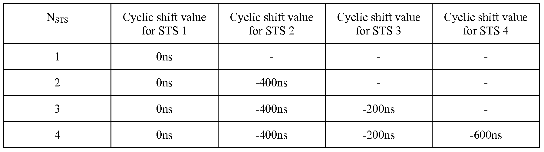
[0031] Throughout the HT-SIG, HT-STF and HT-LTF fields, cyclic shift is applied to prevent beamforming when similar signals are transmitted in different spatial streams. The same cyclic shift is also applied to these streams during the transmission of the data portion of the PPDU. The cyclic shift values to be used during these High-Throughput portions of the PPDU packet are specified by IEEE802.1 In draft specification as follows:
Docket: BCS04307
[0032] At the receiver, channel estimation is performed to the signal that is observed during the transmission of the DLTFs. Channel estimation is performed as follows. For each receive antenna and each subcarrier, the signal received during NDLTF symbol times to estimate NSTS streams can be written as:
Y = HCPs + noise or Yτ = sPT CHT + noise ,
where s is the BPSK symbol on this given subcarrier of the known training sequence, PNSTS corresponds to the weights applied to this symbol, C (NSTSXNSTS) denotes the diagonal matrix related to the cyclic shifts applied to the DLTFs, and H (IXNSTS) is the channel to be estimated.
[0033] Zero-Forcing channel estimation in the frequency domain can then performed by
applying the channel estimator
GNSTS = (SPTC) = S'C' (PPT YP
to the received vector Yτ to get the channel estimate:
Hτ = GNSTSYT
[0034] This equation can be rewritten as:
H = YGLτs
GNSTS defines a class of generic estimators to estimate 1, 2, 3 or 4 equivalent channels. These equivalent channels may correspond to the exact channels if no spatial expansion is
Docket: BCS04307
applied to the LTFs or to the channels experienced by the data LTFs (HQD ) or the Extension LTFs (HQE) if segmented LTFs are applied.
[0035] At the receiver, the channel estimator GWs is applied to the signal observed during the transmission of the DLTFs, which provides an estimate oiHQo that corresponds to the channel experienced by the data and which will be used for decoding of the data. Similarly, the channel estimator GNESS is applied to the signal observed during the transmission of the ELTFs, which gives an estimate OΪHQE. Note that these operations use the estimators that are already implemented for estimation of 1, 2, 3 or 4 channels.
[0036] The exact channel H can then be recovered from the concatenation of the estimated channels: [HQD HQE] = HQ with Q = [QD QE], if the matrix QE is chosen such that the matrix Q has orthogonal columns. The receiver can then feedback to the transmitter CSI matrices, non compressed steering matrices or compressed steering matrices, in order to perform beamforming during subsequent data transmission. [0037] Several illustrative Spatial Expansion schemes for long range sounding PPDUs are presented in FIG. 7. These schemes correspond to the simple duplication of one or two of the STS, and can be applied to the transmission of 2 STS SDM or STBC on 3 or 4 transmit antennas, or to the transmission of 3 STS SDM on 4 antennas. In this case the columns of the matrix QD form an orthogonal basis, but do not have the same norm. The techniques presented above allow these long range Spatial Expansion schemes to be applied to sounding PPDUs. For each Spatial Expansion scheme, the illustrative spatial expansion schemes are characterized by a matrix QE such that the resulting overall matrix Q = [QD QE] can be easily inverted to recover the exact channel H. The inverse of this matrix is also given for each scheme in FIG.86.
[0038] FIG. 8 is a flowchart showing one example of the pertinent steps performed by the MIMO transmitter and receiver. In step 400 the transmitter generates the DLTF symbols that are incorporated in the PPDU frame or packet. Likewise, in steps 405 and 410 the transmitter generates the ELTF symbols and the data symbols, respectively, which are also incorporated in the PPDU frame or packet. In step 415 the transmitter (e.g., spatial mapping block 223 in the transmitter of FIG. 5) applies the spatial expansion matrix QD to the DLTF symbols. Similarly, in step 420 the transmitter applies the spatial expansion matrix QD to the data symbols. In step 425, however, the transmitter applies the extension
Docket: BCS04307
matrix QE to the ELTF symbols. Once the packet is completed with the addition of the appropriate higher level frames (e.g., LLC and MAC frames), the packet can be transmitted in step 430 by, e.g., analog front-end 230 in the transmitter of FIG. 5). At the receiver, the packet undergoes processing to estimate the values for HQD and HQE. Specifically, in step 435 the receiver uses the known values for QD and the known DLTF symbols to estimate the value for HQD, from which the data can be decoded in step 450. Likewise, in step 440 the receiver uses the known values for QE and the known ELTF symbols to estimate the value of HQE. Finally, in step 445 the receiver uses the estimated value of HQD and HQE to estimate the channel transfer function H itself. As previously mentioned, the channel transfer function H may be used to calibrate the receiver and/or to provide feedback (e.g., CSI matrices or steering matrices) to the transmitter so that beamforming may be employed during subsequent transmissions between the transmitter and receiver.
[0039] Although a specific architecture has been described in connection with FIGs. 5-6 herein, including specific functional elements and relationships, it is contemplated that the systems and methods herein may be implemented in a variety of ways. For example, functional elements may be packaged together or individually, or may be implemented by fewer, more or different devices, and may be either integrated within other products, or adapted to work with other products externally. When one element is indicated as being responsive to another element, the elements may be directly or indirectly coupled. [0040] The processes described above, including that shown in FIG. 8, may be implemented in a general, multi-purpose or single purpose processor. Such a processor will execute instructions, either at the assembly, compiled or machine-level, to perform that process. Those instructions can be written by one of ordinary skill in the art following the descriptions herein and stored or transmitted on a computer readable medium. The instructions may also be created using source code or any other known computer-aided design tool. A computer readable medium may be any medium capable of carrying those instructions and includes a CD-ROM, DVD, magnetic or other optical disc, tape, silicon memory (e.g., removable, non-removable, volatile or non-volatile), packetized or non-packetized wireline or wireless transmission signals. [0041] It will furthermore be apparent that other and further forms of the invention, and
Docket: BCS04307
embodiments other than the specific embodiments described above, may be devised without departing from the spirit and scope of the appended claims and their equivalents, and it is therefore intended that the scope of this invention will only be governed by the following claims and their equivalents.
Claims
1. A wireless transmitter, comprising: a stream parser for generating a plurality of spatial streams from a digital signal; a space time block coder (STBC) for mapping each of the spatial streams to a plurality of space-time streams that each include data and a preamble for estimating a channel transfer function; a spatial mapper for spatially expanding each of the space-time streams by applying a spatial expansion matrix to data and to first training symbols used in the preamble to probe a channel experienced by the data and by applying an extension matrix to second training symbols used in the preamble to probe at least one additional dimension of the channel to enable use of beamforming to achieve range extension, wherein the spatial expansion matrix and the extension matrix form an overall matrix that has at least two orthogonal columns with different norms; and an analog front end for modulating the spatially expanded space-time streams onto a wireless carrier.
2. The wireless transmitter of claim 1 wherein the number of space-time streams is equal to 2 and a number of transmit chains is equal to 3, and wherein the spatial expansion matrix QD and the extension matrix QE are as follows:

■ D = diag ((Z1 , ■ ■ ■ , (Zn ) is a diagonal matrix
«1 , ,«„
• θk = -2πkΔFTcs where ΔF is the subcarrier frequency spacing and Tcs is related to a delay applied to a transmit chain Docket: BCS04307
3. The wireless transmitter of claim 11 wherein the number of space-time streams is equal to 2 and a number of transmit chains is equal to 4, and wherein the spatial expansion matrix QD and the extension matrix QE are as follows:

■ a1 ,..., an = diag (ai, ... , an) is a diagonal matrix
• θk = -2πkAFTcs where AF is the subcarrier frequency spacing and Tcsis related to a delay applied to a transmit chain.
4. The wireless transmitter of claim 1 wherein the number of space-time streams is equal to 3 and a number of transmit chains is equal to 4, and wherein the spatial expansion matrix QD and the extension matrix QE are as follows:

(X1 ,..., an = diag (ai, ... , an) is a diagonal matrix Docket: BCS04307
• θk = -2%kt±F%cs where ΔF is the subcarrier frequency spacing and Xcs\'% related to a delay applied to a transmit chain
5. The wireless transmitter of claim 1 wherein the STBC is further configured to apply cyclic shifts to each transmit chain.
6. The wireless transmitter of claim 1 wherein the spatial streams generated by the stream parser include sounding PPDUs that are used to measure channel characteristics.
7. The wireless transmitter of claim 6 wherein the sounding PPDUs are compatible with IEEE 802.11 standards.
Priority Applications (2)
| Application Number | Priority Date | Filing Date | Title |
|---|---|---|---|
| KR1020097026068A KR101239557B1 (en) | 2007-06-15 | 2008-06-11 | Method and apparatus using sounding ppdus to provide range extension to ieee 802.11n signals |
| US12/615,860 US8798202B2 (en) | 2007-06-15 | 2009-11-10 | Method and apparatus using sounding PPDUs to provide range extension to IEEE 802.11n signals |
Applications Claiming Priority (2)
| Application Number | Priority Date | Filing Date | Title |
|---|---|---|---|
| EP20070290745 EP2003808B1 (en) | 2007-06-15 | 2007-06-15 | Apparatus for space time coding using training symbols to provide transmission range extension |
| EP07290745.4 | 2007-06-15 |
Related Child Applications (1)
| Application Number | Title | Priority Date | Filing Date |
|---|---|---|---|
| US12/615,860 Continuation US8798202B2 (en) | 2007-06-15 | 2009-11-10 | Method and apparatus using sounding PPDUs to provide range extension to IEEE 802.11n signals |
Publications (1)
| Publication Number | Publication Date |
|---|---|
| WO2008157149A1 true WO2008157149A1 (en) | 2008-12-24 |
Family
ID=38566920
Family Applications (1)
| Application Number | Title | Priority Date | Filing Date |
|---|---|---|---|
| PCT/US2008/066483 Ceased WO2008157149A1 (en) | 2007-06-15 | 2008-06-11 | Method and apparatus using sounding ppdus to provide range extension to ieee 802.11n signals |
Country Status (4)
| Country | Link |
|---|---|
| EP (1) | EP2003808B1 (en) |
| KR (1) | KR101239557B1 (en) |
| ES (1) | ES2429904T3 (en) |
| WO (1) | WO2008157149A1 (en) |
Cited By (1)
| Publication number | Priority date | Publication date | Assignee | Title |
|---|---|---|---|---|
| JP2022554138A (en) * | 2019-10-31 | 2022-12-28 | ソニーグループ株式会社 | Communication device and method |
Families Citing this family (2)
| Publication number | Priority date | Publication date | Assignee | Title |
|---|---|---|---|---|
| MX2012003190A (en) | 2009-12-10 | 2012-04-30 | Lg Electronics Inc | Method and apparatus of transmitting training signal in wireless local area network system. |
| EP3231100A4 (en) | 2014-12-09 | 2018-07-25 | Celeno Communications (Israel) Ltd. | Su-mimo, mu-mimo and beamforming operations using synchronized wlan devices |
Citations (3)
| Publication number | Priority date | Publication date | Assignee | Title |
|---|---|---|---|---|
| US20040253926A1 (en) * | 2003-06-10 | 2004-12-16 | Gross John N. | Remote monitoring device & process |
| US20070064830A1 (en) * | 2005-09-16 | 2007-03-22 | Samsung Electronics Co., Ltd. | Apparatus and method for extending number of antennas in a wireless communication system using multiple antennas |
| US20070127587A1 (en) * | 2005-12-01 | 2007-06-07 | Samsung Electronics Co., Ltd. | Interleaver design for IEEE 802.11n standard |
Family Cites Families (4)
| Publication number | Priority date | Publication date | Assignee | Title |
|---|---|---|---|---|
| AU2003201162A1 (en) * | 2002-01-04 | 2003-07-15 | Nokia Corporation | High rate transmit diversity transmission and reception |
| US7130580B2 (en) * | 2003-03-20 | 2006-10-31 | Lucent Technologies Inc. | Method of compensating for correlation between multiple antennas |
| BRPI0506904A (en) * | 2004-01-20 | 2007-06-26 | Lg Electronics Inc | method for transmitting / receiving a signal in a minimal system |
| US7894548B2 (en) | 2004-09-03 | 2011-02-22 | Qualcomm Incorporated | Spatial spreading with space-time and space-frequency transmit diversity schemes for a wireless communication system |
-
2007
- 2007-06-15 EP EP20070290745 patent/EP2003808B1/en not_active Not-in-force
- 2007-06-15 ES ES07290745T patent/ES2429904T3/en active Active
-
2008
- 2008-06-11 WO PCT/US2008/066483 patent/WO2008157149A1/en not_active Ceased
- 2008-06-11 KR KR1020097026068A patent/KR101239557B1/en not_active Expired - Fee Related
Patent Citations (3)
| Publication number | Priority date | Publication date | Assignee | Title |
|---|---|---|---|---|
| US20040253926A1 (en) * | 2003-06-10 | 2004-12-16 | Gross John N. | Remote monitoring device & process |
| US20070064830A1 (en) * | 2005-09-16 | 2007-03-22 | Samsung Electronics Co., Ltd. | Apparatus and method for extending number of antennas in a wireless communication system using multiple antennas |
| US20070127587A1 (en) * | 2005-12-01 | 2007-06-07 | Samsung Electronics Co., Ltd. | Interleaver design for IEEE 802.11n standard |
Cited By (2)
| Publication number | Priority date | Publication date | Assignee | Title |
|---|---|---|---|---|
| JP2022554138A (en) * | 2019-10-31 | 2022-12-28 | ソニーグループ株式会社 | Communication device and method |
| US12542578B2 (en) | 2019-10-31 | 2026-02-03 | Sony Group Corporation | Multi-access point communication devices and methods for coordinated join transmission with reduced backhaul requirements |
Also Published As
| Publication number | Publication date |
|---|---|
| ES2429904T3 (en) | 2013-11-18 |
| KR101239557B1 (en) | 2013-03-06 |
| KR20100008001A (en) | 2010-01-22 |
| EP2003808B1 (en) | 2013-09-18 |
| EP2003808A1 (en) | 2008-12-17 |
Similar Documents
| Publication | Publication Date | Title |
|---|---|---|
| US8798202B2 (en) | Method and apparatus using sounding PPDUs to provide range extension to IEEE 802.11n signals | |
| US8787479B2 (en) | Spatial mapping of an OFDM signal to reduce attenuation from an individual transmit antenna in a MIMO transmitter | |
| CN1832480B (en) | Method and system for communicating information in a multiple-input multiple-output communication system | |
| US10123341B2 (en) | Method and apparatus for transmitting data in very high throughput wireless local area network system | |
| US9913168B2 (en) | Method for transmitting PPDU in wireless local area network and apparatus for the same | |
| JP6014948B2 (en) | Sounding packet format for long distance WLAN | |
| CN102893535B (en) | Method and apparatus for transmitting and receiving data in a multiple-input multiple-output system | |
| US8014267B2 (en) | Methods and apparatus for backwards compatible communication in a multiple input multiple output communication system with lower order receivers | |
| CN103069740A (en) | Single-stream phase tracking during channel estimation in very high-throughput wireless MIMO communication systems | |
| US9112744B1 (en) | Noise whitening in a WLAN receiver | |
| US9325532B2 (en) | Method and apparatus for communicating symbols in a multiple input multiple output communication system using interleaved subcarriers across a plurality of antennas | |
| EP2003808B1 (en) | Apparatus for space time coding using training symbols to provide transmission range extension | |
| CN104871470A (en) | Method of communication encoding with space time block codes |
Legal Events
| Date | Code | Title | Description |
|---|---|---|---|
| 121 | Ep: the epo has been informed by wipo that ep was designated in this application |
Ref document number: 08770642 Country of ref document: EP Kind code of ref document: A1 |
|
| ENP | Entry into the national phase |
Ref document number: 20097026068 Country of ref document: KR Kind code of ref document: A |
|
| NENP | Non-entry into the national phase |
Ref country code: DE |
|
| 122 | Ep: pct application non-entry in european phase |
Ref document number: 08770642 Country of ref document: EP Kind code of ref document: A1 |