WO2008114151A2 - Glue application detection system and method - Google Patents
Glue application detection system and method Download PDFInfo
- Publication number
- WO2008114151A2 WO2008114151A2 PCT/IB2008/001392 IB2008001392W WO2008114151A2 WO 2008114151 A2 WO2008114151 A2 WO 2008114151A2 IB 2008001392 W IB2008001392 W IB 2008001392W WO 2008114151 A2 WO2008114151 A2 WO 2008114151A2
- Authority
- WO
- WIPO (PCT)
- Prior art keywords
- glue
- paper substrate
- direct contact
- paper
- substrate
- Prior art date
- Legal status (The legal status is an assumption and is not a legal conclusion. Google has not performed a legal analysis and makes no representation as to the accuracy of the status listed.)
- Ceased
Links
Classifications
-
- A—HUMAN NECESSITIES
- A24—TOBACCO; CIGARS; CIGARETTES; SIMULATED SMOKING DEVICES; SMOKERS' REQUISITES
- A24C—MACHINES FOR MAKING CIGARS OR CIGARETTES
- A24C5/00—Making cigarettes; Making tipping materials for, or attaching filters or mouthpieces to, cigars or cigarettes
- A24C5/47—Attaching filters or mouthpieces to cigars or cigarettes, e.g. inserting filters into cigarettes or their mouthpieces
- A24C5/471—Attaching filters or mouthpieces to cigars or cigarettes, e.g. inserting filters into cigarettes or their mouthpieces by means of a connecting band
- A24C5/472—Applying adhesives to the connecting band
-
- B—PERFORMING OPERATIONS; TRANSPORTING
- B05—SPRAYING OR ATOMISING IN GENERAL; APPLYING FLUENT MATERIALS TO SURFACES, IN GENERAL
- B05C—APPARATUS FOR APPLYING FLUENT MATERIALS TO SURFACES, IN GENERAL
- B05C11/00—Component parts, details or accessories not specifically provided for in groups B05C1/00 - B05C9/00
- B05C11/10—Storage, supply or control of liquid or other fluent material; Recovery of excess liquid or other fluent material
- B05C11/1002—Means for controlling supply, i.e. flow or pressure, of liquid or other fluent material to the applying apparatus, e.g. valves
- B05C11/1015—Means for controlling supply, i.e. flow or pressure, of liquid or other fluent material to the applying apparatus, e.g. valves responsive to a conditions of ambient medium or target, e.g. humidity, temperature ; responsive to position or movement of the coating head relative to the target
-
- B—PERFORMING OPERATIONS; TRANSPORTING
- B05—SPRAYING OR ATOMISING IN GENERAL; APPLYING FLUENT MATERIALS TO SURFACES, IN GENERAL
- B05C—APPARATUS FOR APPLYING FLUENT MATERIALS TO SURFACES, IN GENERAL
- B05C5/00—Apparatus in which liquid or other fluent material is projected, poured or allowed to flow on to the surface of the work
- B05C5/02—Apparatus in which liquid or other fluent material is projected, poured or allowed to flow on to the surface of the work the liquid or other fluent material being discharged through an outlet orifice by pressure, e.g. from an outlet device in contact or almost in contact, with the work
Definitions
- the present invention relates to a reliable method and apparatus for detecting minute quantities of glue applied onto a paper substrate in a high speed operation.
- glue is applied to tipping paper in the manufacture of cigarette, and the tipping paper is then cut to length and wrapped around a cigarette filter and wrapped tobacco rod to thereby secure the filter to the rod.
- the absence of glue on the tipping paper could ultimately cause filter falloff. Detecting the presence/absence of the glue as it is applied is a preemptive measure to prevent loss of quality or product failure latter in the process.
- the primary object of the present invention is a reliable method and apparatus for detecting the presence/absence of minute quantities of glue on a paper substrate in a high speed operation in a highly efficient manner.
- an endless paper substrate is traveling at a high rate of speed, and glue is applied to selected surface portions on one side of the paper.
- glue Prior to the application of glue, the paper travels over a first direct contact capacitive sensor which measures the dielectric constant of the paper and outputs a first signal representative of that measurement.
- the paper with the glue thereon travels over a second direct contact capacitive sensor which measures the dielectric constant of both the paper and glue and outputs a signal representative of that measurement.
- the paper with wet glue has a demonstrable difference as opposed to dry paper or paper without glue, and this difference is utilized as an indicator that glue has in fact been applied to the paper. Without applied glue there is little or no difference between the signals, and the lack of difference is utilized as an indication of a defect which is thereafter corrected.
- Figure 1 is a schematic side elevational view of an endless paper substrate traveling at a high rate of speed and a system for detecting the presence/absence of glue applied to the substrate, in accordance with the present invention
- Figure 2 is a perspective diagrammatic view of one of two direct contact capacitive sensors used in the system of Figure 1 , according to the present invention.
- the present invention involves a reliable method for detecting minute quantities of glue in a high speed operation. Fundamentally, the method relies on measuring the 'relative permittivity' or 'dielectric constant' of paper with wet glue applied.
- the formula which explains the overall sensing system can be expressed as follows:
- the dielectric constant of water is such a large value, that paper with wet glue has a demonstrable difference as opposed to dry paper or paper without glue.
- the paper may be held a fixed distance from detecting pates, and the area of the plates is held constant by design.
- the moisture in the paper manifests itself by changes in the value of "C" in the above formula. This value is detected and compared with acceptable limits and decisions are made by appropriate software to accept or reject a defective product.
- considerations for external variables may be addressed by the addition of a reference sensor.
- the purpose of the reference sensor is to measure the material before the glue is applied and subtract this measured value from the sensor measuring the paper after the glue is applied. The remainder from this calculation represents only the moisture content of the glue. All other variables are nullified. In this way, it is possible to utilize this technology to detect moisture content in additional applications/processes besides glue.
- Figure 1 illustrates a system 10 for detecting the presence/absence of glue 12 applied to an endless paper substrate 14 traveling at a high rate of speed.
- the paper substrate may comprise tipping paper, for example, used to secure a cigarette filter to a wrapped tobacco rod after the filter and tobacco rod are joined together.
- system 10 includes first and second direct contact capacitive sensors 16, 18, one for determining the relative permittivity or dielectric constant of the dry paper and the other for determining the relative permittivity or dielectric constant of the paper with wet glue applied thereto.
- Each sensor 16, 18 may comprise a generally flat surface having a first sensing plate in the form of an inner ring 20 and a second sensing plate in the form of an outer ring 22.
- an electric field 24 is produced between the rings.
- a gap 26 is defined between the rings, and as explained above when the area of the plates or rings 20, 22 and the gap 26 between them remains fixed the capacitive value in the above formula changes proportionately with the relative permittivity or dielectric constant of the material placed between the two rings 22, 24.
- the first sensor 16 outputs a signal to a control box 28 which is representative of the dielectric constant of the dry paper 14 while the second sensor 18 outputs a signal to control box 28 representative of the dielectric constant of the paper 14 and the glue 12.
- a control box 28 which is representative of the dielectric constant of the dry paper 14
- the second sensor 18 outputs a signal to control box 28 representative of the dielectric constant of the paper 14 and the glue 12.
- Glue presence measurement utilizing capacitive detection allows for accurate measurement of the presence/absence of glue.
- the utilization of direct contact sensors 16, 18 on the non-glued side of the paper 14 eliminates the effect of 'flutter' on the detection system. Additionally, by using a capacitive sensor, the effects of humidity and/or air density are eliminated. Also, since each detector receives its power from the same source 28, electrical noise/power supply variation is nullified as well.
- the system 10 is quite accurate because the 'trigger' for detecting a fault condition is based on a comparison of the input signals before and after glue is applied as opposed to a 'set' threshold value. In this way, variations in paper thickness/density are forgiven.
- Figure 1 represents glue detection for a single side of the paper 14.
- the reference detector 16 can be utilized by both signal conditioning modules. With the reference sensor 16 the intrinsic value of the 'paper 1 or product other than glue is subtracted from the output of sensor 18. In this way the accuracy of the detection device 10 is significantly improved.
- the present detection device is 'self calibrating 1 and self adjusting. In this way, little if any human intervention is required.
Landscapes
- Investigating Or Analyzing Materials By The Use Of Electric Means (AREA)
- Paper (AREA)
- Geophysics And Detection Of Objects (AREA)
Abstract
A glue application method and system (10) comprises a continuous paper substrate (14) moving in a downstream direction along a path of travel. Glue (12) is applied to selected portions of the upper surface of the paper substrate (14). A first direct contact capacitive sensor (16) under the paper substrate (14) upstream of glue application and in direct contact with the under surface of the paper substrate (14) produces a signal representative of the dielectric constant of the paper substrate (14). A second direct contact capacitive sensor (18) under the paper substrate (14) downstream of glue application and in direct contact with the under surface of the paper substrate (14) with glue (12) thereon produces a second signal representative of the dielectric constant of the paper substrate (14) with glue (12) thereon. A control (28) determines differences between the first and second signals thereby indicating that glue has been applied to the paper substrate.
Description
GLUE APPLICATION DETECTION SYSTEM AND METHOD
BACKGROUND OF THE INVENTION
The present invention relates to a reliable method and apparatus for detecting minute quantities of glue applied onto a paper substrate in a high speed operation.
In many instances the application of glue to a paper substrate is a critical step in a manufacturing process. For example, glue is applied to tipping paper in the manufacture of cigarette, and the tipping paper is then cut to length and wrapped around a cigarette filter and wrapped tobacco rod to thereby secure the filter to the rod. The absence of glue on the tipping paper could ultimately cause filter falloff. Detecting the presence/absence of the glue as it is applied is a preemptive measure to prevent loss of quality or product failure latter in the process.
SUMMARY OF THE INVENTION
Accordingly, the primary object of the present invention is a reliable method and apparatus for detecting the presence/absence of minute quantities of glue on a paper substrate in a high speed operation in a highly efficient manner.
In accordance with the present invention, an endless paper substrate is traveling at a high rate of speed, and glue is applied to selected surface portions on one side of the paper. Prior to the application of glue, the paper travels over a first direct contact capacitive sensor which measures the dielectric constant of the paper and outputs a first signal representative of that measurement. After the application of glue, the paper with the glue thereon travels over a second direct contact capacitive sensor which measures the dielectric constant of both the paper and glue and outputs a signal representative of that measurement. The paper with wet glue has a demonstrable difference as opposed to dry paper or paper without glue, and this difference is utilized as an indicator that glue has in fact been applied to the paper. Without applied glue there is little or no difference between the signals, and the lack of difference is utilized as an indication of a defect which is thereafter corrected.
BRIEF DESCRIPTION OF THE DRAWINGS
Novel features and advantages of the present invention in addition to those noted above will be become apparent to persons of ordinary skill in the art from a reading of the following detailed description in conjunction with the accompanying drawings wherein similar reference characters refer to similar parts and in which:
Figure 1 is a schematic side elevational view of an endless paper substrate traveling at a high rate of speed and a system for detecting the presence/absence of glue applied to the substrate, in accordance with the present invention; and
Figure 2 is a perspective diagrammatic view of one of two direct contact capacitive sensors used in the system of Figure 1 , according to the present invention.
DETAILED DESCRIPTION OF THE INVENTION
The present invention involves a reliable method for detecting minute quantities of glue in a high speed operation. Fundamentally, the method relies on measuring the 'relative permittivity' or 'dielectric constant' of paper with wet glue applied. The formula which explains the overall sensing system can be expressed as follows:
Area x Dielectric
C = Gap
One can readily see that, if the area of the sensing plates and the distance (gap) between them remains fixed, then the value of 'C will change proportionately with the dielectric constant of whatever material is placed between the two plates.
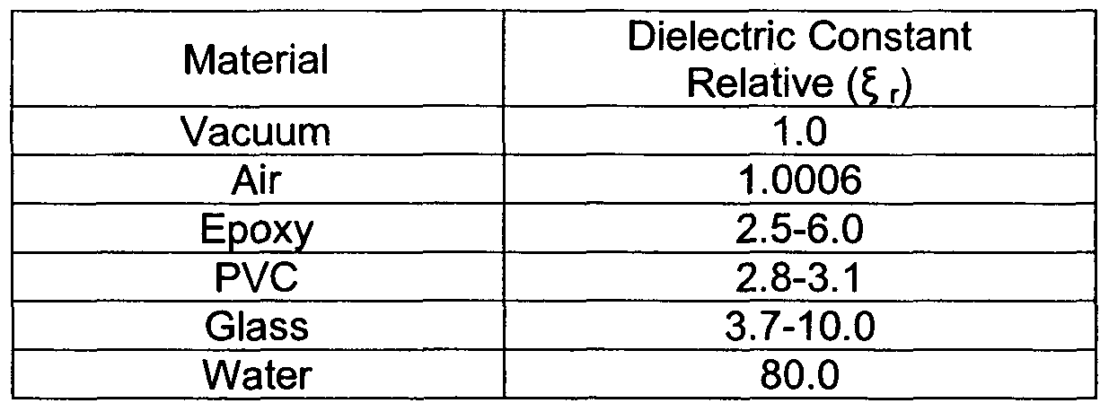
The dielectric constant of water is such a large value, that paper with wet glue has a demonstrable difference as opposed to dry paper or paper without glue.
The paper may be held a fixed distance from detecting pates, and the area of the plates is held constant by design. The moisture in the paper manifests itself by changes in the value of "C" in the above formula. This value is detected and compared with acceptable limits and decisions are made by appropriate software to accept or reject a defective product. Additionally, considerations for external variables may be addressed by the addition of a reference sensor. The purpose of the reference sensor is to measure the material before the glue is applied and subtract this measured value from the sensor measuring the paper after the glue is applied. The remainder from this calculation represents only the moisture content of the glue. All other variables are nullified. In this
way, it is possible to utilize this technology to detect moisture content in additional applications/processes besides glue.
Referring in more particularly to the drawings, Figure 1 illustrates a system 10 for detecting the presence/absence of glue 12 applied to an endless paper substrate 14 traveling at a high rate of speed. The paper substrate may comprise tipping paper, for example, used to secure a cigarette filter to a wrapped tobacco rod after the filter and tobacco rod are joined together. As explained more fully below, system 10 includes first and second direct contact capacitive sensors 16, 18, one for determining the relative permittivity or dielectric constant of the dry paper and the other for determining the relative permittivity or dielectric constant of the paper with wet glue applied thereto.
Each sensor 16, 18 may comprise a generally flat surface having a first sensing plate in the form of an inner ring 20 and a second sensing plate in the form of an outer ring 22. When energized an electric field 24 is produced between the rings. A gap 26 is defined between the rings, and as explained above when the area of the plates or rings 20, 22 and the gap 26 between them remains fixed the capacitive value in the above formula changes proportionately with the relative permittivity or dielectric constant of the material placed between the two rings 22, 24.
The first sensor 16 outputs a signal to a control box 28 which is representative of the dielectric constant of the dry paper 14 while the second sensor 18 outputs a signal to control box 28 representative of the dielectric constant of the paper 14 and the glue 12. When the difference between the signals is significant, the process continues. On the other hand, when there is little or no difference, such condition is an indication of the absence of glue and corrective measures are taken.
Glue presence measurement utilizing capacitive detection allows for accurate measurement of the presence/absence of glue. The utilization of direct contact sensors 16, 18 on the non-glued side of the paper 14 eliminates the effect of 'flutter' on the detection system. Additionally, by using a capacitive sensor, the effects of humidity and/or air density are eliminated. Also, since each detector receives its power from the same source 28, electrical noise/power supply variation is nullified as well. The system 10 is quite accurate because the 'trigger' for detecting a fault condition is based on a comparison of the input signals before and after glue is applied as opposed to a 'set' threshold value. In this way, variations in paper thickness/density are forgiven.
Figure 1 represents glue detection for a single side of the paper 14. However, to detect the presence of glue on both the front and rear edge of the paper, for example, a duplicate detection system is required. The reference detector 16 can be utilized by both signal conditioning modules.
With the reference sensor 16 the intrinsic value of the 'paper1 or product other than glue is subtracted from the output of sensor 18. In this way the accuracy of the detection device 10 is significantly improved. Moreover, the present detection device is 'self calibrating1 and self adjusting. In this way, little if any human intervention is required.
Claims
1. A glue application detection system comprising: a continuous paper substrate moving in a downstream direction along a path of travel; a glue applicator for applying glue to selected portions of an upper surface of the paper substrate; a first direct contact capacitive sensor under the paper substrate upstream of the glue applicator and in direct contact with an under surface of the substrate constructed and arranged to produce a first signal representative of the dielectric constant of the paper substrate; a second direct contact capacitive sensor under the paper substrate downstream of the glue applicator and in direct contract with an under surface of the substrate with glue thereon constructed and arranged to produce a second signal representative of the dielectric constant of the paper substrate with glue thereon; and a control for determining differences between the first and second signals thereby indicating that glue has been applied to the paper substrate.
2. A glue application detecting system as in claim 1 wherein each of the first and second direct contact capacitive sensors includes a flat surface having a first plate in the form of an inner ring and a second plate in the form of outer ring with a gap between the rings.
3. A method of detecting the presence/absence of glue applied to a paper substrate comprising the steps of:
(a) moving a continuous paper substrate in a downstream direction along a path of travel;
(b) applying glue to selected portions of an upper surface of the paper substrate;
(c) positioning a first direct contact capacitive sensor under the paper substrate upstream of the glue applicator and in direct contact with an under surface of the substrate for producing a first signal representative of the dielectric constant of the paper substrate;
(d) positioning a second direct contact capacitive sensor under the paper substrate downstream of the glue applicator and in direct contact with an under surface of the substrate with glue thereon for producing a second signal representative of the dielectric constant of the paper substrate with glue thereon; and
(e) determining differences between the first and second signals thereby indicating that glue has been applied to the paper substrate.
Applications Claiming Priority (2)
| Application Number | Priority Date | Filing Date | Title |
|---|---|---|---|
| US89398107P | 2007-03-09 | 2007-03-09 | |
| US60/893,981 | 2007-03-09 |
Publications (2)
| Publication Number | Publication Date |
|---|---|
| WO2008114151A2 true WO2008114151A2 (en) | 2008-09-25 |
| WO2008114151A3 WO2008114151A3 (en) | 2008-11-27 |
Family
ID=39745208
Family Applications (1)
| Application Number | Title | Priority Date | Filing Date |
|---|---|---|---|
| PCT/IB2008/001392 Ceased WO2008114151A2 (en) | 2007-03-09 | 2008-03-06 | Glue application detection system and method |
Country Status (2)
| Country | Link |
|---|---|
| US (1) | US20080245463A1 (en) |
| WO (1) | WO2008114151A2 (en) |
Families Citing this family (2)
| Publication number | Priority date | Publication date | Assignee | Title |
|---|---|---|---|---|
| TWI553310B (en) * | 2015-04-02 | 2016-10-11 | 致伸科技股份有限公司 | Adhesion state detection method |
| CN106153684A (en) * | 2015-04-15 | 2016-11-23 | 致伸科技股份有限公司 | Method for detecting adhesion state |
Family Cites Families (6)
| Publication number | Priority date | Publication date | Assignee | Title |
|---|---|---|---|---|
| US4389969A (en) * | 1981-06-22 | 1983-06-28 | Copar Corporation | Glue detector |
| DE3220629C2 (en) * | 1982-06-01 | 1984-12-13 | Bernhard Dipl.-Ing.(TH) 7800 Freiburg Ehret | Control device for gluing endless sets |
| DE3909990A1 (en) * | 1989-03-25 | 1990-09-27 | Bat Cigarettenfab Gmbh | DEVICE FOR DETECTING SUFFICIENT GLUING OF A PAPER STRIP TO BE GLUED |
| US6021782A (en) * | 1997-10-03 | 2000-02-08 | R.J. Reynolds Tobacco Company | Method of and system for cigarette tipping glue skip detection and rejection |
| US6470294B1 (en) * | 1999-04-13 | 2002-10-22 | Qualitek-Vib, Inc. | System and method for the on-line measurement of glue application rate on a corrugator |
| DE10028000A1 (en) * | 2000-06-08 | 2001-12-13 | Hauni Maschinenbau Ag | Method and device for feeding a partially perforated covering paper strip for ventilated cigarettes |
-
2008
- 2008-03-04 US US12/041,953 patent/US20080245463A1/en not_active Abandoned
- 2008-03-06 WO PCT/IB2008/001392 patent/WO2008114151A2/en not_active Ceased
Also Published As
| Publication number | Publication date |
|---|---|
| US20080245463A1 (en) | 2008-10-09 |
| WO2008114151A3 (en) | 2008-11-27 |
Similar Documents
| Publication | Publication Date | Title |
|---|---|---|
| FI81203B (en) | FOERFARANDE OCH ANORDNING FOER MAETNING AV VATTENHALT. | |
| US6470294B1 (en) | System and method for the on-line measurement of glue application rate on a corrugator | |
| US8896826B2 (en) | Inspection system for coated paper | |
| JP3372193B2 (en) | Cigarette manufacturing equipment | |
| KR20230069146A (en) | Packing Tightness Online Detection System for Cigarette Packets | |
| WO2017031569A1 (en) | Holmium oxide glasses as calibration standards for near infrared moisture sensors | |
| CN111227299A (en) | System and method for on-line continuous inspection and control of acetate fiber and plasticizer in filter rod production process | |
| JP5359671B2 (en) | Film thickness measuring apparatus and film thickness measuring method | |
| WO2008114151A2 (en) | Glue application detection system and method | |
| ATE134973T1 (en) | DOUBLE ARCH DETECTION | |
| JPH01309673A (en) | Method and apparatus for determining air permeability of rod-shaped article in tobacco processing industry | |
| US20070006655A1 (en) | Glue quantity determination | |
| CN203737615U (en) | Glue detection device for midline glue of cigarette filter | |
| CN103196832B (en) | A kind of pick-up unit of pipe tobacco water cut and method | |
| JP2004314347A (en) | Inspection device for inspecting pasting of sheet for box | |
| JP2022522856A (en) | Inspection stations and methods for inspecting sheet materials | |
| CN216547106U (en) | A trademark paper inspection device for a packaging machine | |
| ATE325338T1 (en) | METHOD FOR DETECTING AIR HUMIDITY USING A CAPACITIVE HUMIDITY MEASURING ELEMENT | |
| CN204359740U (en) | Filter stick formation paper gluing pick-up unit | |
| CN214524853U (en) | Cigarette packet cigarette dew and seal skew detection device and cigarette packaging machine | |
| GB2247952A (en) | Apparatus for conveying a flat article | |
| US20040177912A1 (en) | Corrugating machine with multiple thermal position sensing | |
| JPS5972047A (en) | Method for measuring moisture of powdered body | |
| JP3574320B2 (en) | Seal bite inspection method | |
| JP2004101412A (en) | Pinhole defect inspection equipment for skive hemming |
Legal Events
| Date | Code | Title | Description |
|---|---|---|---|
| NENP | Non-entry into the national phase |
Ref country code: DE |
|
| 122 | Ep: pct application non-entry in european phase |
Ref document number: 08762748 Country of ref document: EP Kind code of ref document: A2 |