WO2008109912A1 - Distributed turbo coding and relaying protocols - Google Patents
Distributed turbo coding and relaying protocols Download PDFInfo
- Publication number
- WO2008109912A1 WO2008109912A1 PCT/AU2007/001729 AU2007001729W WO2008109912A1 WO 2008109912 A1 WO2008109912 A1 WO 2008109912A1 AU 2007001729 W AU2007001729 W AU 2007001729W WO 2008109912 A1 WO2008109912 A1 WO 2008109912A1
- Authority
- WO
- WIPO (PCT)
- Prior art keywords
- node
- relay
- signal
- signals
- source
- Prior art date
Links
Classifications
-
- H—ELECTRICITY
- H04—ELECTRIC COMMUNICATION TECHNIQUE
- H04B—TRANSMISSION
- H04B7/00—Radio transmission systems, i.e. using radiation field
- H04B7/14—Relay systems
- H04B7/15—Active relay systems
- H04B7/155—Ground-based stations
- H04B7/15557—Selecting relay station operation mode, e.g. between amplify and forward mode, decode and forward mode or FDD - and TDD mode
-
- H—ELECTRICITY
- H03—ELECTRONIC CIRCUITRY
- H03M—CODING; DECODING; CODE CONVERSION IN GENERAL
- H03M13/00—Coding, decoding or code conversion, for error detection or error correction; Coding theory basic assumptions; Coding bounds; Error probability evaluation methods; Channel models; Simulation or testing of codes
- H03M13/03—Error detection or forward error correction by redundancy in data representation, i.e. code words containing more digits than the source words
- H03M13/05—Error detection or forward error correction by redundancy in data representation, i.e. code words containing more digits than the source words using block codes, i.e. a predetermined number of check bits joined to a predetermined number of information bits
- H03M13/09—Error detection only, e.g. using cyclic redundancy check [CRC] codes or single parity bit
-
- H—ELECTRICITY
- H03—ELECTRONIC CIRCUITRY
- H03M—CODING; DECODING; CODE CONVERSION IN GENERAL
- H03M13/00—Coding, decoding or code conversion, for error detection or error correction; Coding theory basic assumptions; Coding bounds; Error probability evaluation methods; Channel models; Simulation or testing of codes
- H03M13/29—Coding, decoding or code conversion, for error detection or error correction; Coding theory basic assumptions; Coding bounds; Error probability evaluation methods; Channel models; Simulation or testing of codes combining two or more codes or code structures, e.g. product codes, generalised product codes, concatenated codes, inner and outer codes
- H03M13/2957—Turbo codes and decoding
Definitions
- This invention concerns distributed turbo coding and relaying protocols in wireless relay networks.
- the invention concerns a method for relaying signals at a relay node, a method for processing signals at a destination node, a relay system and software to perform the methods.
- a spatial diversity can be achieved by a multiple-input- multiple-output (MIMO) system by exploiting space time coding.
- MIMO multiple-input- multiple-output
- a mobile terminal or wireless sensor nodes may not be possible for a mobile terminal or wireless sensor nodes to equip with multiple transmit antennas.
- a new form of diversity technique called user cooperation diversity or distributed spatial diversity
- the idea is to allow different users to communicate cooperatively and share their antennas to achieve a virtual MIMO link, thus achieving a spatial diversity gain.
- the relayed transmission can be viewed as a good example of distributed diversity techniques.
- the source sends the source information to the relays.
- the relays detect the received signals, reconstruct them and then forward them to the destination.
- a distributed diversity can be achieved.
- the invention is a method for relaying signals at a relay node in a wireless network comprising a source node, a destination node and one or more relay nodes; the method comprising the steps of: receiving a signal from a first node; decoding the received signal; and if the received signal is decoded incorrectly, employing an Amplify-And- Forward (AAF) relaying protocol comprising the steps of amplifying the received signal and then transmitting the amplified signal to a second node; but otherwise, employing a Decode-And-Forward (DAF) relaying protocol comprising the steps of re-encoding the decoded signal and then transmitting the coded signal to the second node.
- AAF Amplify-And- Forward
- DAF Decode-And-Forward
- the first node may be a source node or relay node.
- the second node may be a relay node or a destination node.
- the received signal may be amplified by an amplification factor that varies according to the transmit power constraint of the relay node and the power of the signal received from the first node.
- the DAF relaying protocol may further comprise the step of interleaving the coded signal before transmitting it to the second node
- the method may further comprise the steps of receiving a control signal from the second node after an initial signal transmission to the second node; the control signal informing the relay node to either continue or stop relaying signals from the first node to the second node.
- the relay node may further receive a control signal from the second node after an initial signal transmission to the second node; and depending on the control signal, the relay node may continue or stop relaying the signal received from the first node to the second node.
- the second node may select the best relay node to relay signals from the first node.
- the invention is a method for processing signals at a destination node in a wireless relay network comprising a source node, a destination node and one or more relay nodes; the method comprising the steps of: receiving a signal containing data from the source node; receiving signals from one or more relay nodes, where each relay node either employs an Amplify-And-Forward (AAF) relaying protocol or a Decode-And-Forward (DAF) relaying protocol depending on whether the relay node can correctly decode a signal received from the source node; recovering data transmitted by the source node by combining all signals received from the source and relay nodes and then decoding the combined signal.
- AAF Amplify-And-Forward
- DAF Decode-And-Forward
- the received signals may be combined so as to maximise the Signal-to-Noise Ratio (SNR) of the combined signal.
- SNR Signal-to-Noise Ratio
- the combined signal may then be decoded using a Viterbi decoding algorithm.
- a cyclic redundancy check may be performed to determine whether a signal has been successfully decoded at the relay node.
- CRC bits are appended to each block of information bits (a frame).
- the decoded CRC bits can be checked for errors.
- the method may further comprise the steps of: determining the Signal-to-Noise Ratio (SNR) of the channel between the destination node and each relay node; determining the best relay node, that is a relay node that has the maximum SNR at the destination node; and transmitting a control signal to all relay nodes; the control signal informing the best relay node to continue relaying and informing other relay nodes to stop relaying.
- SNR Signal-to-Noise Ratio
- the control signal may be transmitted to each relay node via a feedback channel or a reverse broadcast channel. After the initial transmission cycle, only the best relay node will relay signal from the source node to the destination node, where the best relay node either employs an AAF or a DAF protocol.
- the step of recovering data transmitted by the source node may comprise the steps of: determining the relaying protocol employed by each relay node; constructing a first signal by combining the received signal from the source node with amplified signals from relay nodes employing the AAF protocol; constructing a second signal by combining coded and interleaved signals from relay nodes employing the DAF protocol; and decoding the first and second signals using a turbo iterative decoding algorithm to recover data transmitted by the source node.
- the above scheme is known as distributed turbo decoding with adaptive relaying, where the first and second signals form a distributed code
- the invention is a relay system comprising: a source node to send signals containing coded data to a destination node and one or more relay nodes; one or more relay nodes to receive signals from the source node and depending on whether the received signal can be decoded correctly, to either employ an Amplify-
- And-Forward or a Decode-And-Forward protocol and transmit a signal to the destination node; and a destination node to receive signals from the source and relay nodes, to combine the signals received and to decode the combined signal in order to recover the data transmitted by the source node.
- the invention is a software to implement the method for relaying signals at a relay node in a wireless relay network; the method as described above.
- the invention is a software to implement the method for processing signals at a destination node in a wireless relay network; the method as described above.
- the invention takes advantages of both the DAF and AAF protocols but minimise their negative affects.
- AAF-only protocols usually suffer from noise amplification while DAF-only protocols propagate error through imperfect decoding when channel quality from the source to the relay is poor.
- the relaying protocol is automatically adapted to the channel quality by simply switching between the AAF and the DAF without any need for the channel state information (CSI) to be fed back from the destination to the relays or the source. This is very important in practical relay networks, especially in a multi-hop large network, in which the feedback of CSI for adaptation is very expensive.
- adaptive relaying with relay selection facilitates system design for non- orthogonal channels and may improve system performance and capacity.
- the overall received codeword at the destination consists of the combined coded information symbols received from the AAF relay group and the combined coded interleaved information symbols transmitted from the DAF relay group.
- the invention may provide not only SNR gain, but also coding gain due to tne use of distributed turbo coding.
- Fig. 1 is a block diagram of adaptive relaying protocol (ARP) in a 2-hop wireless relay network exemplifying the invention.
- ARP adaptive relaying protocol
- Fig. 2 is a detailed diagram of the operation at the destination in Fig. 1.
- Fig. 3 is a block diagram of adaptive relaying protocol with relay selection (RS- ARP).
- Fig. 4 is a block diagram of adaptive relaying protocol with distributed turbo decoding (DTC-ARP).
- Fig. 5 is a block diagram of adaptive relaying protocol with relay selection and distributed turbo decoding (DTC-RS-ARP).
- Figs. 6(a), (b) and (c) show the FER performance of the adaptive relaying protocol (ARP) in a 2-hop network.
- ARP adaptive relaying protocol
- Figs. 7(a) and (b) show the FER performance of adaptive relaying protocol (ARP) in a 2-hop network with 1 and 2 relays, respectively.
- ARP adaptive relaying protocol
- Figs. 8(a) and (b) show the FER performance of adaptive relaying protocol (ARP) in a 2-hop network with 4 and 8 relays, respectively.
- Figs. 9(a), (b) and (c) show the FER performance of adaptive relaying protocol with relay selection (RS-ARP) in a 2-hop network with 2, 4 and 8 relays, respectively.
- Figs. 10(a) and (b) show the FER performance of adaptive relaying protocol with distributed turbo decoding (DTC-ARP) for 1 and 2 relays, respectively.
- DTC-ARP distributed turbo decoding
- Figs. 11 (a) and (b) show the FER performance of adaptive relaying protocol with distributed turbo decoding (DTC-ARP) for 4 and 8 relays, respectively.
- Figs. 12(a), (b) and (c) show the FER performance of adaptive relaying protocol with relay selection and distributed turbo decoding (DTC-RS-ARP) in a 2-hop network with 2, 4 and 8 relays, respectively.
- a general 2-hop relay network 100 consisting of one source 110, ⁇ relays 300 and one destination 200 with a direct link from the source 110 to the destination 200. There may be more than one relay between the source 110 and the destination 200, forming a multi-hop network.
- the transmitted source information binary stream denoted by B
- B the transmitted source information binary stream
- B (b(l),- -,b(k),- -,b(l)) (1) where b(k) is a binary symbol transmitted at time k and / is the frame length.
- the binary information sequence B is first encoded by a channel encoder.
- a channel encoder For simplicity, we consider a recursive systematic convolutional code (RSCC) with a code rate of 1/2.
- RSCC recursive systematic convolutional code
- the binary symbol stream C is then mapped into a modulated signal stream S.
- S (S(I),- • -,S(O) (3)
- the source and relays transmit data through orthogonal channels.
- the transmission channels for all relays are orthogonal, such that the transmitted signals from each relay can be separated at the destination without any interference from other relays.
- the source first broadcasts the information to both the destination and relays.
- n sr i (k,j) and n sd (k,j) are zero mean complex Gaussian random variables with two sided power spectral density of N 0 /2 per dimension.
- All noise processes are of the same variance without loss of generality. Different noise variances can be taken into account by appropriately adjusting the channel gain.
- the relays 300 then process the received signals transmitted from the source and send them to the destination.
- Let x rJ (k, j) represent the signal transmitted from the relay i at time 2(Ar-I)+/. It satisfies the following transmit power constraint,
- P is the transmitted power limit at the relay /.
- the corresponding received signal at the destination 200 at time 2(k-l)+j denoted by y r d,i(kj) > can be written as where G r complex fading coefficient between the relay i and destination and n rd i (k,j) is a zero mean complex Gaussian random variable with two sided power spectral density of 7VQ/2 per dimension.
- ARP Adaptive Relaying Protocol
- Fig. 1 shows the operation of a relay 300 in detail.
- each relay Upon receiving signals from the source 110, each relay decodes the received signal; step 305.
- each relay In each transmission, based on whether relays can decode correctly or not, each relay is included into either of two groups, an AAF relay group 335 and a DAF relay group 330. All relays in the AAF relay group amplify the received signals from the source and forward it to the destination (325 and 340), while all the relays in the DAF relay group will decode the received signals, re-encode and forward them to the destination (320 and 340).
- Amplify-And-Forward (AAF ⁇ ) Relay Group 335 An AAF relay group, denoted by ⁇ . AAF , consists of all the relays, which could not decode correctly. Since each relay in the AAF relay group cannot decode correctly, upon receiving signal from the source, it will simply amplify the received signal from the source and forward it to the destination; 325 and 340 in Fig. 1.
- x r i (k,j) i e O, MF
- x r j (K J) Wrj (K j) , i e ⁇ ⁇ (7)
- ⁇ is an amplification factor such that From (8), the amplification factor ⁇ . can be calculated as:
- the received signals at the destination, at time 2(Ic- 1)+/, transmitted from the relay z can be expressed as: Decode-And-Forward (OAF) Relay Group 330
- a DAF relay group denoted by ⁇ DAF , consists of all the relays, which can decode successfully.
- each relay in the DAF relay group Upon receiving signals from the source, each relay in the DAF relay group will decode the received signals from the source, re-encode and send them to the destination; 310 and 320 in Fig. 1.
- each relay in the DAF relay group can accordingly recover the binary information stream B.
- B is then encoded into C and modulated into S.
- the relay / in the DAF relay group will then forward the modulated symbols S with power P r ( , to the destination; see 340 in Fig. 1,
- the destination SNR for the combined signals denoted by ⁇ ARP , can be calculated from (13) as
- Equation (17) J. ⁇ . Laneman and G. W. Wornell, "Energy-efficient antenna sharing and relaying for wireless networks,” in Proc. IEEE WC ⁇ C, 2000, pp. 7-12. From Equation (17), we can then calculate the received SNR for the combined signals as follows,
- a Viterbi decoding algorithm can then be used to obtain information estimates; see 220 in Fig. 2.
- the branch metrics of the Viterbi decoding algorithm is calculated as:
- the conditioned pairwise error probability (PEP) that the decoder decides in favour of another erroneous codeword with Hamming weight dj, for the above scenario, is given by: where Q(x) denotes the Q function.
- the PEP can be derived by averaging Equation (23) over the fading coefficients.
- P( ? )(di) be the PEP of decoding an erroneous code sequence with weight d ⁇ , then we have
- K 0 (x) and K 1 (X) are the zero- and first-order modified Bessel function of the second kind.
- P F sr represent the average upper bound for word error probability in the channel from the source to the relay:
- Equation (33) can be further expressed as: J where represents the BER increase of the ARP compared to the perfect DAF under the same SNR.
- P b ARP be the average upper bound on the bit error rate (BER) for the ARP.
- BER bit error rate
- Equation (33) the average PEP of the ARP in Equation (33) can also be expressed as
- Equation (41) It can be easily proved from Equation (41) that for high ⁇ rd value, G ARPIA ⁇ F is a decreasing function of ⁇ sr . Therefore G ARP/AAF decreases as ⁇ sr increases, and the ARP can achieve a considerable error rate reduction compared to the AAF under the same ⁇ sr and ⁇ rd values. This error rate reduction exponentially grows as the number of relays increases.
- the destination will first calculate the received SNR for each relay in both AAF and DAF groups. From Equation (10), the destination SNR for z-th relay in the AAF group can be calculated as,
- the destination SNR fory-th relay in the DAF group can be calculated as: Among all relays in both AAF and DAF groups, the destination will select one relay, denoted by S, which has the maximum destination SNR,
- the destination After finding the optimum relay S, through a feedback channel or a reverse broadcast channel, the destination will inform which relay is selected for transmission and other unselected relays will be in an idle state. For example, if the ith relay has the best SNR at the destination, the "index of optimal relay" will be set to i, requiring only the selected relay to relay the signal from the source 110; see 240 in Fig. 3.
- the dashed arrows in Fig. 3 represent communications with non-selected relays.
- the selected relay S is from the AAF relay group, it will amplify and forward the received signal transmitted from the source and if it is selected from the DAF group, it will decode and forward the received signals. At destination, Viterbi decoding can then be used to obtain the information estimates.
- wher i A _ mm and z D _ max represent the relay with maximum destination SNR in the AAF and DAF groups, respectively.
- Equation (49) After substituting Equation (49) into (47) and (48), can be further calculated as
- Equation (57) Equation (57)
- Equation (59) can be further approximated as
- p q represent the probability that the AAF relay group consists of any q relays and the DAF relay group consists of the rest (n-q) relays and it is given by: where P F sr is the average upper bound for word error probability in the channel from the source to the relay, given by: where ⁇ ⁇ ) , and p(d sr I z) is the probability that an input word with Hamming weight i produces a codeword with Hamming weight d sr .
- Equation (63) From Equation (63), we can observe that a diversity order of (n+1) can be achieved for an RS-ARP scheme in a relay networks with n relays at a higher ⁇ sr region.
- the average PEP of incorrectly decoding to a codeword with weight dj denoted by P ⁇ %% , can be calculated as: where B(x,y) is a beta function.
- Equation (63) can be further expressed as: where represents the BER increase of the RS-ARP compared to the perfect DAF-Selection under the same SNR.
- Equation (63) By comparing with in Equation (63) can be further expressed as (69) where represents the BER reduction of the RS-ARP compared to the AAF-selection.
- G RS _ ARP/A ⁇ F _ S is a decreasing function of ⁇ , for high ⁇ rd values. Therefore for a fixed ⁇ rd , G RS _ ARPIAAF _ S significantly decreases as ⁇ sr increases, and the RS-ARP can achieve a considerable error rate reduction compared to the AAF selection under the same SNR. This error rate reduction exponentially grows as the number of relays increases.
- DTC-ARP Distributed Turbo Coding with ARP
- the adaptive relaying protocol (ARP) is combined with distributed turbo coding.
- ARP adaptive relaying protocol
- all the relays in the AAF relay group amplify the received signals from the source and forward them to the destination, while the relays in the DAF relay group decode the received signals, interleave the decoded symbols, re-encode and forward them to the destination.
- Each relay in the DAF group decodes the received signals, interleaves the decoded symbols, re-encodes and transmits it to the destination. Let represent the interleaved version of B. Let denote the codeword of B 5 where is the codeword of is then mapped into a modulated signal stream where is the modulated signal transmitted by the relays in the DAF relay group, at time 2(k-l) +j.
- the relay i in the DAF ⁇ elay group will then forward the modulated symbols S with power P 1 . . , to the destination,
- n rd DAF ⁇ k,j is an equivalent noise after combination, with ze mean and a variance of
- An overall codeword at the destination consists of the combined coded information symbols transmitted from the AAF relay group and the combined coded symbols of the interleaved information sequence sent from the DAF relay group. They form a distributed turbo code.
- I(k) represent the interleaved position of k.
- y MFJnfo (k) and y DAFJ ⁇ (k) be the combined signal and its interleaved one.
- the extrinsic information of one decoder is used to update the a priori probability of the other decoder in the next iteration. After several iterations, the decision is made based on the APPs of the first decoder.
- the average PEP of the DTC-ARP at high SNR can be approximated as
- Adaptive relaying protocol ARP
- distributed turbo coding DTC
- RS relay selection
- -,DTC-SSR (d) denote the average PEP of the DTC-RS-ARP that the decoder decides in favour of another erroneous codeword with Hamming weight d in this case, and it can be approximated at high SNR as The average PEP at high SNR can be approximated as
- DAF relay protocol requires relays to fully decode the source information and this limits the performance of DAF to that of direct transmission between the source and relays, so it does not offer a diversity gain.
- Fig. 6 The FER performance of the AAF and the proposed ARP, as a function of ⁇ rd and with ⁇ sr as a parameter is shown in Fig. 6.
- the cases of ⁇ sr IdB, 7dB and 13 dB are illustrated in Figs. 6(a), (b) and (c), respectively.
- the ARP can get a considerable coding gain compared to the AAF in the whole ⁇ rd region and this gain increases as the number of relays increases.
- Equation (41) For low ⁇ sr value, ⁇ rd l ⁇ sr » 1 , corresponding to the region of high ⁇ rd values in Figs. 3-4, Equation (41) can be approximated
- the performance gain can be easily explained in the following way.
- the channel from the source to the relays is very noisy and probabilities of decoding errors at each relay are very high, so most of relays cannot correctly decode the received signals.
- the probability that the DAF group includes at least one relay is l-(P F sr )" .
- l — ⁇ P FtSr approaches 0 and most of relays are included in the AAF relay group at very high chance and the DAF relay group only occasionally includes few relays, thus in this case, the ARP and the AAF have the similar performance.
- n - 1, 2, 4 and 8 relays are illustrated in Figs. 7(a), 7(b), 8(a) and 8(b), respectively.
- the ARP significantly outperforms the AAF in the all SNR regions, and performs close to the perfect DAF as ⁇ sr increases.
- the performance gap between the ARP and the perfect DAF also increases. This can also be observed from the theoretical results shown in Equation (36).
- Equation (36) For a fixed ⁇ rd , as ⁇ sr increases,
- the FER performance of the AAF-selection, the proposed RS-ARP and the perfect DAF-selection for various number of relays, as a function of ⁇ rd and with ⁇ sr as a parameter is shown in Fig. 9.
- the cases of When the quality of channel from the source to the relay is poor, as for example for ⁇ sr ⁇ B, it can be observed that the RS-ARP outperforms the AAF-selection at low ⁇ rd values.
- the RS-ARP can get a significant coding gain compared to the AAF-selection in the whole ⁇ rd region. This gain will be significantly increased as the number of relays increases.
- Fig. 9 also compare the performance of the RS-ARP with the perfect DAF-selection for various numbers of relays.
- the cases of n — 2, 4 and 8 relays are illustrated in Figs. 9(a), (b) and (c), respectively. It can be noted that as ⁇ sr increases, the RS-ARP performs very close to the perfect DAF-selection.
- DTC-RS-ARP The performance of DTC-RS-ARP with DTC-ARP for various number relays is shown in Fig. 12.
- the cases of n 2, 4 and 8 relays are illustrated in Figs. 12(a), (b) and (c), respectively.
- ⁇ sr the DTC-ARP outperforms the DTC-SR-ARP.
- ⁇ sr increases
- DTC-RS-ARP is significantly superior to the DTC-ARP. This can be explained as follows.
- the system is benefited from two major gains, received SNR gain contributed from relay selection and coding gain from the distributed turbo coding (DTC).
- DTC distributed turbo coding
- the DAF group In order to form a DTC codeword at the destination, the DAF group should include at least one relay. Let P DAF represent such a probability and it is given by
- DTC-ARP In the DTC-ARP, all the relays in the DAF group will participate in the relayed transmission. However, in the DTC-RS-ARP, only the relay with the maximum destination SNR is selected for transmission and it could be selected from either AAF or DAF group. At very low ⁇ sr values, P DAF is already very small, therefore the probability that the selected relay is from a DAF group becomes even much smaller compared to the DTC-ARP. In this case, DTC-ARP can provide more coding gain than the DTC-RS-ARP and the DTC-RS-ARP can provide more SNR gain.
- the received SNR gain dominate the system performance because the DTC will not provide the system much coding gain at low SNR values, in this case, the DTC-RS- ARP can bring system a considerable SNR gain compared to the DTC-ARP.
- the coding gain contributed from the DTC will also increases and dominate the system performance and in this case the DTC-ARP outperforms the DTC- RS-ARP.
- P DAF also significantly increases and both schemes contribute to the system similar coding gain, but the DTC-RS-ARP can provide more SNR gain compared to the DTC-ARP, thus has much better performance.
- the DTC-RS-ARP approaches the perfect DTC-RS-ARP very closely.
- a signal may be relayed to more than one relay nodes before reaching the destination node.
Landscapes
- Engineering & Computer Science (AREA)
- Computer Networks & Wireless Communication (AREA)
- Signal Processing (AREA)
- Mobile Radio Communication Systems (AREA)
Abstract
This invention concerns distributed turbo coding and relaying protocols in wireless relay networks. In particular, the invention concerns a method for relaying signals at a relay node, a method for processing signals at a destination node, a relay system and software to perform the methods. The wireless relay networks comprise a source node, a destination node and one or more relay nodes. At a relay node, the invention comprises the steps of receiving a signal from a first node; decoding the received signal; and if the received signal is decoded incorrectly, employing an Amplify-And- Forward (AAF) relaying protocol comprising the steps of amplifying the received signal and then transmitting the amplified signal to a second node; but otherwise, employing a Decode- And-Forward (DAF) relaying protocol comprising the steps of re-encoding the decoded signal and then transmitting the coded signal to the second node. At a destination node, data transmitted by the source node is recovered by combining all signals received from the source and relay nodes and then decoding the combined signal.
Description
Title
Distributed Turbo Coding and Relaying Protocols
Technical Field This invention concerns distributed turbo coding and relaying protocols in wireless relay networks. In particular, the invention concerns a method for relaying signals at a relay node, a method for processing signals at a destination node, a relay system and software to perform the methods.
Background Art
In wireless communication systems, diversity has been an effective technique in combating detrimental effects of channel fading caused by multi-path propagation and Doppler shift. Specifically, a spatial diversity can be achieved by a multiple-input- multiple-output (MIMO) system by exploiting space time coding. However, in a cellular network or wireless sensor networks, due to the limited size, cost and hardware limitation, it may not be possible for a mobile terminal or wireless sensor nodes to equip with multiple transmit antennas.
To overcome such limitation, a new form of diversity technique, called user cooperation diversity or distributed spatial diversity, has been proposed recently, for cooperative cellular networks or wireless sensor networks. The idea is to allow different users to communicate cooperatively and share their antennas to achieve a virtual MIMO link, thus achieving a spatial diversity gain. The relayed transmission can be viewed as a good example of distributed diversity techniques. In the relay channel, the source sends the source information to the relays. The relays detect the received signals, reconstruct them and then forward them to the destination. At the destination, by properly combining the received signals from the source and relays, a distributed diversity can be achieved.
Disclosure of Invention
In a first aspect, the invention is a method for relaying signals at a relay node in a wireless network comprising a source node, a destination node and one or more relay nodes; the method comprising the steps of: receiving a signal from a first node; decoding the received signal; and
if the received signal is decoded incorrectly, employing an Amplify-And- Forward (AAF) relaying protocol comprising the steps of amplifying the received signal and then transmitting the amplified signal to a second node; but otherwise, employing a Decode-And-Forward (DAF) relaying protocol comprising the steps of re-encoding the decoded signal and then transmitting the coded signal to the second node.
The first node may be a source node or relay node. The second node may be a relay node or a destination node.
The received signal may be amplified by an amplification factor that varies according to the transmit power constraint of the relay node and the power of the signal received from the first node.
The DAF relaying protocol may further comprise the step of interleaving the coded signal before transmitting it to the second node
The method may further comprise the steps of receiving a control signal from the second node after an initial signal transmission to the second node; the control signal informing the relay node to either continue or stop relaying signals from the first node to the second node.
The relay node may further receive a control signal from the second node after an initial signal transmission to the second node; and depending on the control signal, the relay node may continue or stop relaying the signal received from the first node to the second node. Using this relay-selection protocol, the second node may select the best relay node to relay signals from the first node.
In a second aspect, the invention is a method for processing signals at a destination node in a wireless relay network comprising a source node, a destination node and one or more relay nodes; the method comprising the steps of: receiving a signal containing data from the source node; receiving signals from one or more relay nodes, where each relay node either employs an Amplify-And-Forward (AAF) relaying protocol or a Decode-And-Forward (DAF) relaying protocol depending on whether the relay node can correctly decode a signal received from the source node;
recovering data transmitted by the source node by combining all signals received from the source and relay nodes and then decoding the combined signal.
The received signals may be combined so as to maximise the Signal-to-Noise Ratio (SNR) of the combined signal.
The combined signal may then be decoded using a Viterbi decoding algorithm.
A cyclic redundancy check (CRC) may be performed to determine whether a signal has been successfully decoded at the relay node. At the source transmitter CRC bits are appended to each block of information bits (a frame). At each relay the decoded CRC bits can be checked for errors.
During an initial transmission cycle between each relay node and the destination node, the method may further comprise the steps of: determining the Signal-to-Noise Ratio (SNR) of the channel between the destination node and each relay node; determining the best relay node, that is a relay node that has the maximum SNR at the destination node; and transmitting a control signal to all relay nodes; the control signal informing the best relay node to continue relaying and informing other relay nodes to stop relaying.
The control signal may be transmitted to each relay node via a feedback channel or a reverse broadcast channel. After the initial transmission cycle, only the best relay node will relay signal from the source node to the destination node, where the best relay node either employs an AAF or a DAF protocol.
It may be assumed, for the purposes of calculation, that the channel does not change during each frame, so the best relay may be selected for each frame of data.
The step of recovering data transmitted by the source node may comprise the steps of: determining the relaying protocol employed by each relay node; constructing a first signal by combining the received signal from the source node with amplified signals from relay nodes employing the AAF protocol;
constructing a second signal by combining coded and interleaved signals from relay nodes employing the DAF protocol; and decoding the first and second signals using a turbo iterative decoding algorithm to recover data transmitted by the source node.
The above scheme is known as distributed turbo decoding with adaptive relaying, where the first and second signals form a distributed code
In a third aspect, the invention is a relay system comprising: a source node to send signals containing coded data to a destination node and one or more relay nodes; one or more relay nodes to receive signals from the source node and depending on whether the received signal can be decoded correctly, to either employ an Amplify-
And-Forward or a Decode-And-Forward protocol and transmit a signal to the destination node; and a destination node to receive signals from the source and relay nodes, to combine the signals received and to decode the combined signal in order to recover the data transmitted by the source node.
In another aspect, the invention is a software to implement the method for relaying signals at a relay node in a wireless relay network; the method as described above.
In a further aspect, the invention is a software to implement the method for processing signals at a destination node in a wireless relay network; the method as described above.
The invention takes advantages of both the DAF and AAF protocols but minimise their negative affects. AAF-only protocols usually suffer from noise amplification while DAF-only protocols propagate error through imperfect decoding when channel quality from the source to the relay is poor. Using the invention, the relaying protocol is automatically adapted to the channel quality by simply switching between the AAF and the DAF without any need for the channel state information (CSI) to be fed back from the destination to the relays or the source. This is very important in practical relay networks, especially in a multi-hop large network, in which the feedback of CSI for adaptation is very expensive.
Additionally, adaptive relaying with relay selection facilitates system design for non- orthogonal channels and may improve system performance and capacity. By requiring only the signal from the relay having the best transmit Signal-to-Noise Ratio (SNR), other relays in the network do not have to relay the signal. Since channels may not be perfectly orthogonal in practice, this strategy reduces interference to the best relay, source and destination. Besides, other relays may conserve battery power by not having to relay signals when channel quality between the relays and the destination is poor.
Using distributed turbo coding with adaptive relaying, the overall received codeword at the destination consists of the combined coded information symbols received from the AAF relay group and the combined coded interleaved information symbols transmitted from the DAF relay group. When adaptive relaying and relay selection are combined with distributed turbo coding, the invention may provide not only SNR gain, but also coding gain due to tne use of distributed turbo coding.
Brief Description of the Drawings
An example of the invention will now be described with reference to the accompanying drawings, in which: Fig. 1 is a block diagram of adaptive relaying protocol (ARP) in a 2-hop wireless relay network exemplifying the invention.
Fig. 2 is a detailed diagram of the operation at the destination in Fig. 1. Fig. 3 is a block diagram of adaptive relaying protocol with relay selection (RS- ARP). Fig. 4 is a block diagram of adaptive relaying protocol with distributed turbo decoding (DTC-ARP).
Fig. 5 is a block diagram of adaptive relaying protocol with relay selection and distributed turbo decoding (DTC-RS-ARP).
Figs. 6(a), (b) and (c) show the FER performance of the adaptive relaying protocol (ARP) in a 2-hop network.
Figs. 7(a) and (b) show the FER performance of adaptive relaying protocol (ARP) in a 2-hop network with 1 and 2 relays, respectively.
Figs. 8(a) and (b) show the FER performance of adaptive relaying protocol (ARP) in a 2-hop network with 4 and 8 relays, respectively. Figs. 9(a), (b) and (c) show the FER performance of adaptive relaying protocol with relay selection (RS-ARP) in a 2-hop network with 2, 4 and 8 relays, respectively.
Figs. 10(a) and (b) show the FER performance of adaptive relaying protocol with distributed turbo decoding (DTC-ARP) for 1 and 2 relays, respectively.
Figs. 11 (a) and (b) show the FER performance of adaptive relaying protocol with distributed turbo decoding (DTC-ARP) for 4 and 8 relays, respectively. Figs. 12(a), (b) and (c) show the FER performance of adaptive relaying protocol with relay selection and distributed turbo decoding (DTC-RS-ARP) in a 2-hop network with 2, 4 and 8 relays, respectively.
Best Modes of the Invention Referring first to Fig. 1, we consider a general 2-hop relay network 100, consisting of one source 110, π relays 300 and one destination 200 with a direct link from the source 110 to the destination 200. There may be more than one relay between the source 110 and the destination 200, forming a multi-hop network.
At the source 110, the transmitted source information binary stream, denoted by B, is represented by
B = (b(l),- -,b(k),- -,b(l)) (1) where b(k) is a binary symbol transmitted at time k and / is the frame length.
The binary information sequence B is first encoded by a channel encoder. For simplicity, we consider a recursive systematic convolutional code (RSCC) with a code rate of 1/2. Let C represent the corresponding codeword, given by
C = (C(I),- -C(A:), -,C(/)) (2) where C(k)=(b(k), c(k) is the codeword of b(k), c(k)e {0, 1}, b(k) is the information symbol and c(k) is the corresponding parity symbol.
The binary symbol stream C is then mapped into a modulated signal stream S. For simplicity, we consider a BPSK modulation. The modulated codeword, denoted by S, is given by: S = (S(I),- • -,S(O) (3) where S(k) = (s(k,l),s(k,2J) , s(k,j) e {-l,+l}, h=l,...,I,j=l, 2, is the modulated signal transmitted by the source at time 2(Ar-I) +j .
We assume that the source and relays transmit data through orthogonal channels. For simplicity, we will concentrate on a time division multiplex, for which the source and relays transmit in the separate time slots and all relays transmit to the destination at the
same time. We also assume that the transmission channels for all relays are orthogonal, such that the transmitted signals from each relay can be separated at the destination without any interference from other relays.
The source first broadcasts the information to both the destination and relays. The received signals at the relay i, z-1 ,...,«, and the destination, at time 2 (Ar-I)+/, denoted by ysrj(k,j) and yscι(k,j), respectively, which can be expressed as:
 where: are the received signal power at the relay and destination,

 are the channel gains between the source and the relay i and
 between the source and destination, respectively; dsr i and dsd are the distances between the source and relay i, and that between the source and destination, respectively; do is a reference distance; λc is the carrier wavelength and K is a path loss factor with values typically in the range 1 < K < 4 . Also, hsr i and hsd are the fading coefficients between the source and relay i, and between the source and destination, respectively. They are modelled as zero-mean, independent circular symmetric complex Gaussian random variables.
We consider a quasi-static fading channel, for which the fading coefficients are constant within one frame and change independently from one frame to another. Furthermore, nsr i(k,j) and nsd(k,j) are zero mean complex Gaussian random variables with two sided power spectral density of N0/2 per dimension. We also assume that all noise processes are of the same variance without loss of generality. Different noise variances can be taken into account by appropriately adjusting the channel gain.
The relays 300 then process the received signals transmitted from the source and send them to the destination. Let xrJ (k, j) represent the signal transmitted from the relay i at time 2(Ar-I)+/. It satisfies the following transmit power constraint,

where P,.,, is the transmitted power limit at the relay /.
The corresponding received signal at the destination 200 at time 2(k-l)+j, denoted by yrd,i(kj)> can be written as
 where Gr complex fading coefficient between the relay i and destination and nrd i(k,j) is a zero mean complex Gaussian random variable with two sided power spectral density of 7VQ/2 per dimension.
Adaptive Relaying Protocol (ARP)
Fig. 1 shows the operation of a relay 300 in detail. Upon receiving signals from the source 110, each relay decodes the received signal; step 305. In each transmission, based on whether relays can decode correctly or not, each relay is included into either of two groups, an AAF relay group 335 and a DAF relay group 330. All relays in the AAF relay group amplify the received signals from the source and forward it to the destination (325 and 340), while all the relays in the DAF relay group will decode the received signals, re-encode and forward them to the destination (320 and 340).
Amplify-And-Forward (AAF^) Relay Group 335 An AAF relay group, denoted by Ω.AAF , consists of all the relays, which could not decode correctly. Since each relay in the AAF relay group cannot decode correctly, upon receiving signal from the source, it will simply amplify the received signal from the source and forward it to the destination; 325 and 340 in Fig. 1. Let xr i(k,j) , i e O,MF , represent the signal transmitted from the relay i at time 2(Ar-I)+/, then it can be expressed as: xrj (K J) = Wrj (K j) , i e Ω ^ (7) where μ, is an amplification factor such that
 From (8), the amplification factor μ. can be calculated as:

By substituting (9) and (1) into (7), the received signals at the destination, at time 2(Ic- 1)+/, transmitted from the relay z, can be expressed as:
 Decode-And-Forward (OAF) Relay Group 330
A DAF relay group, denoted by ΩDAF , consists of all the relays, which can decode successfully. Upon receiving signals from the source, each relay in the DAF relay group will decode the received signals from the source, re-encode and send them to the destination; 310 and 320 in Fig. 1.
Since all the relays in the DAF relay group can decode correctly, each relay in the DAF relay group can accordingly recover the binary information stream B. B is then encoded into C and modulated into S. The relay / in the DAF relay group will then forward the modulated symbols S with power Pr ( , to the destination; see 340 in Fig. 1,

The received signals at the destination 200, transmitted from the relay i in the DAF relay group, become

Signal Processing at Destination 200
Referring now to Fig. 2, all signals received at the destination, forwarded from the source 110, the AAF 335 and DAF 330 groups, are combined into one signal as follows:

(13)
The destination SNR for the combined signals, denoted by γARP , can be calculated from (13) as


Substitute (15) into (13), we have


J. Ν. Laneman and G. W. Wornell, "Energy-efficient antenna sharing and relaying for wireless networks," in Proc. IEEE WCΝC, 2000, pp. 7-12.
From Equation (17), we can then calculate the received SNR for the combined signals as follows,

By substituting (9) into (17), γARP can further approximated by


After combining signals as in equation (16), a Viterbi decoding algorithm can then be used to obtain information estimates; see 220 in Fig. 2. The branch metrics of the Viterbi decoding algorithm is calculated as:

Performance Analysis of ARP
Calculation of the traditional union bound requires knowing the code distance spectrum, which needs an exhaustive search of the code trellis. Due to a high complexity of this search, we consider an average upper bound. For simplicity of calculation, we assume that γsι ι = γsr and γrd ι = γld for all i=l,...,n.
( 1 ) Error probability of the ARP Let us first calculate the pairwise error probability (PEP) for a scenario where the AAF relay group consists of q relays numbered from 1 to q and the DAF relay group consists of (n-q) relays numbered from (#+1) to n.
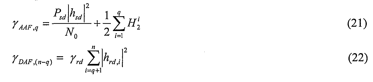
Let TAAFM and ΪDAFin-q) represent the instantaneous received SNR of the combined signals in the AAF and DAF relay groups. For simplicity, we include the destination signal directly transmitted from the source into the AAF relay group, then we have the following from Equation (19):
The conditioned pairwise error probability (PEP) that the decoder decides in favour of another erroneous codeword with Hamming weight dj, for the above scenario, is given by:
 where Q(x) denotes the Q function.
The PEP can be derived by averaging Equation (23) over the fading coefficients. Let P(?)(di) be the PEP of decoding an erroneous code sequence with weight d\, then we have

Since all are independent variables and are also

 independent to each other, the inequality (24) can be further written as:
wher


The closed form expression of fυ)(d:) can be calculated by using the moment generating function (MDF) of the Harmonic mean of two exponential random variables. The exact closed form expression of f^{dλ) is too complex to be presented it here.
 can be approximated as:
 By substituting (28) into (25), we have:

Let PF sr{dsr,γsr i I hsr l) be the conditional pair- wise error probability (PEP) of incorrectly decoding a codeword into another codeword with Hamming distance of dsr in the channel from the source to the relay i . Since we assume that χsrJ = γsr for all v=\, 2, ..., n, then we have:

Let PF sr represent the average upper bound for word error probability in the channel from the source to the relay:
where
 the number of words with Hamming weight i and p(dsr \ ϊ) is the probability that an input word with Hamming weight i produces a codeword with Hamming weight dsr.
Due to the uniform distribution of the relays and assumption of γsr i = γsr and Yrdj = Yrd f°r a^ z-1 >• • •>«> the probability that the AAF relay group consists of any q relays and the DAF relay group consists of the rest (n-q) relays is the same and is given by:
where

Then the average PEP at high SNR can be calculated as: PΛRP{dλ)

Similarly, for a perfect DAF, in which all relay are assumed to decode correctly, the average PEP of incorrectly decoding to a codeword with weight dj, denoted by
 can be calculated as:


It can be noted that as and the
 performance of the ARP approaches the perfect DAF.
Let Pb ARP be the average upper bound on the bit error rate (BER) for the ARP. At high SNR, Pb ARP can be approximated as
performance of the ARP approaches the perfect DAF.
Let Pb ARP be the average upper bound on the bit error rate (BER) for the ARP. At high SNR, Pb ARP can be approximated as


From equations (37-38), we can observe that a diversity order of (n+l) can be achieved for an ARP scheme in a relay network with n relays at a higher γsr region.
(2) Error probability of the AAF
Following the similar analysis, the average PEP of the AAF of incorrectly decoding to a codeword with weight d, denoted by PMF (d) , can be similarly calculated as

Compared to PAAF(dλ) , the average PEP of the ARP in Equation (33) can also be expressed as


It can be easily proved from Equation (41) that for high γrd value, GARPIAΛF is a decreasing function of γsr . Therefore GARP/AAF decreases as γsr increases, and the ARP can achieve a considerable error rate reduction compared to the AAF under the same γsr and γrd values. This error rate reduction exponentially grows as the number of relays increases.
Relay Selection Algorithm with Adaptive Relay Protocol (RS-ARP)
As shown in Fig. 3, adaptive relaying may be combined with relay selection. Similarly, each relay i 300, i = 1, ..., n, is either in the AAF relay group or the DAF relay group.
However, after receiving signals from all relays, the destination will first calculate the received SNR for each relay in both AAF and DAF groups. From Equation (10), the destination SNR for z-th relay in the AAF group can be calculated as,

Similarly, from Equation (12), the destination SNR fory-th relay in the DAF group can be calculated as:
 Among all relays in both AAF and DAF groups, the destination will select one relay, denoted by S, which has the maximum destination SNR,

After finding the optimum relay S, through a feedback channel or a reverse broadcast channel, the destination will inform which relay is selected for transmission and other unselected relays will be in an idle state. For example, if the ith relay has the best SNR at the destination, the "index of optimal relay" will be set to i, requiring only the
selected relay to relay the signal from the source 110; see 240 in Fig. 3. The dashed arrows in Fig. 3 represent communications with non-selected relays.
If the selected relay S is from the AAF relay group, it will amplify and forward the received signal transmitted from the source and if it is selected from the DAF group, it will decode and forward the received signals. At destination, Viterbi decoding can then be used to obtain the information estimates.
Performance Analysis of RS-ARP In this section, we analyze the performance of the RS-ARP. For simplicity of calculation, we assume that

( 1 ) Error probability of the RS-ARP
We first calculate the pairwise error probability (PEP) of RS-ARP for a scenario where the AAF relay group consists of q relays numbered from 1 to q and the DAF relay group consists of {n-q) relays numbered from (#+1) to n.
Let and represent the received destination signals, at time k,

 with the m instantaneous received SNRs, in the AAF and DAF, respectively. Also, let and TDTF ,(«-?) represent the corresponding SNR, then

Let and denote the signals after combining and


 at the destination, with corresponding SNR nd

 then we have


After substituting Equation (49) into (47) and (48), can be
 further calculated as
where

Let n then the PDF of can be approximated at high


 SNR as:
 while t PDF of rZFχ,,-q) is Siven hT-

Let
 represent the destination SNR of the optimal relay in both AAF and DAF groups at the destination. Then we have

The conditioned pairwise error probability (PEP) that the decoder decides in favour of another erroneous codeword with Hamming weight di, for the above scenario, is given


(58) By using the Taylor series, we have:

At high SNR, thus by ignoring the terms of second and higher
 order of y in the above series, Equation (59) can be further approximated as


Then the average PEP of the RS-ARP at high SNR can be approximated as

From Equation (63), we can observe that a diversity order of (n+1) can be achieved for an RS-ARP scheme in a relay networks with n relays at a higher γsr region.
Similarly, for a perfect DAF-Selection, in which all relay are assumed to decode correctly, the average PEP of incorrectly decoding to a codeword with weight dj, denoted by Pζ%% , can be calculated as:
 where B(x,y) is a beta function.
At high SNR, it can be approximated as

Equation (63) can be further expressed as:
 where
where
 represents the BER increase of the RS-ARP compared to the perfect DAF-Selection under the same SNR.
It can be noted that as either
 performance of the RS-ARP approaches the perfect DAF-Selection.
(2) Error probability of the AAF-Selection
Following the similar analysis, for the AAF-Selection, the average PEP of incorrectly decoding to a codeword with weight d\, denoted by PAAF~s{dx) , can be calculated at

By comparing with in Equation (63) can be further expressed
 as (69)
 where
where
 represents the BER reduction of the RS-ARP compared to the AAF-selection.
It can be proved that GRS_ARP/AΛF_S is a decreasing function of ^, for high γrd values. Therefore for a fixed γrd , GRS_ARPIAAF_S significantly decreases as γsr increases, and
the RS-ARP can achieve a considerable error rate reduction compared to the AAF selection under the same SNR. This error rate reduction exponentially grows as the number of relays increases.
Distributed Turbo Coding with ARP (DTC-ARP)
Referring now to Fig. 4, the adaptive relaying protocol (ARP) is combined with distributed turbo coding. Using this protocol, all the relays in the AAF relay group amplify the received signals from the source and forward them to the destination, while the relays in the DAF relay group decode the received signals, interleave the decoded symbols, re-encode and forward them to the destination.
Specifically, all signals forwarded from the AAF relay group, at time 2(Ar-I)+/, are combined with the signals directly transmitted from the source (see 212 in Fig. 4), as follows,
 where yrdtAAF(k,j) is the combined signal at time 2(Ar-I)+/,

Each relay in the DAF group decodes the received signals, interleaves the decoded symbols, re-encodes and transmits it to the destination. Let
 represent the interleaved version of B. Let
 denote the codeword of B 5 where
 is the codeword of
 is then mapped into a modulated signal stream where is the

 modulated signal transmitted by the relays in the DAF relay group, at time 2(k-l) +j.
The relay i in the DAF ϊelay group will then forward the modulated symbols S with power P1. . , to the destination,

The received signals at the destination, transmitted from the relay i in the DAF relay group (see 214 in Fig. 4), become:

At the destination, all signals forwarded from the DAF relay group, at time 2(k-l)+j, are then combined together. Let yrd>DΛF (k, j) represent the combined signal, given by:

where and nrd DAF {k,j) is an equivalent noise after combination,
 with ze mean and a variance of
From Equations (35) and (39), the received SNR for the combined signals in the AAF and DAF relay group, denoted by, γ^p and γDAF , can be calculated as

An overall codeword at the destination consists of the combined coded information symbols transmitted from the AAF relay group and the combined coded symbols of the interleaved information sequence sent from the DAF relay group. They form a distributed turbo code.
Let I(k) represent the interleaved position of k. For a RSC code, yrdMF (k,ϊ) and y~ rd,DAF (I(k),l) , k=\,...,l, carry the same information symbol b(k), thus they should be properly combined before sending to each decoder. Let yMFJnfo (k) and yDAFJΦ (k) be the combined signal and its interleaved one. Following the similar calculations as in the AAF and DAF groups, the optimal combination of yrdtAAF(k,Y) and yrdιDAF(I(k),ϊ) can be formulated as follows:
 and
and
 where /~'(/c) represents the de-interleaved position of k. Let
 24
24

These two signals are then sent to two MAP decoders associated with y^ and yDAF , respectively. A turbo iterative decoding algorithm is then performed between these two decoders; see 220 in Fig. 4. The decoders with y MF and y DΛF as input symbols calculate the a posteriori probability (APP) of the information symbols and the interleaved information symbols, denoted by P\b{k) ~ w \ yAAF) and P(b(k) = w\ yDAF), and the corresponding extrinsic information, respectively. The extrinsic information of one decoder is used to update the a priori probability of the other decoder in the next iteration. After several iterations, the decision is made based on the APPs of the first decoder.


There is one possible scenario that for some transmission blocks there are no relays that can make correct decoding. This could happen at low signal to noise ratios. In this case, there are no relays in the DAF relay group and all relays are in AAF relay group, so we only need to decode yrd<AAF , from which we get the information symbol estimates.
Performance Analysis of DTC-ARP
We first consider a scenario where the AAF relay group consists of q relays numbered from 1 to q and the DAF relay group consists of (n-q) relays numbered from (q+l) to n. The conditional pairwise error probability (PEP) that the decoder decides in favor of another erroneous codeword with Hamming weight d, for the above scenario, is given by:
 wher d\ and J2 are the Hamming weights of the erroneous codewords with Hamming weight d, transmitted from the AAF and DAF group, respectively, such that d = dx + d2 .
By averaging (47) with respect to the channel, we have

The average PEP of the DTC-ARP at high SNR can be approximated as

Similarly, for a perfect DTC, for which all relay can decode correctly, the average PEP of incorrectly decoding to a codeword with weight d, denoted by Pζ^ct (d) , can be calculated as:
 (85) can be further written as:
 where represents the BER increase of the DTC-

ARP compared to the perfect DTC under the same SNR.
It can be noted that as
 and the performance of the DTC-ARP approaches the perfect DTC.
Distributed Turbo Coding with Relay Selection using Adaptive Relaying Protocol
(DTC-RS-ARP)
Adaptive relaying protocol (ARP), distributed turbo coding (DTC) and relay selection (RS) may be further combined in a protocol shown in Fig. 5. Among all the relays, we select one relay with maximum destination SNR. If the selected relay is from a DAF group, it will decode the received signals, interleave, re-encode and forward them to the destination. At destination, the signals directly transmitted from the source and that from the selected relay in the DAF group will form a DTC codeword. If it is selected from an AAF group, it will amplify and forward the signals to the destination. We refer to such a scheme as the DTC with single selected relay (DTC-RS-ARP).
Similar to the performance analysis for ARP, RS-ARP and DTC-ARP, we first consider the case when the AAF relay group consists of q relays numbered from 1 to q and the DAF relay group consists of (n-q) relays numbered from (#+1) to n. Let
-,DTC-SSR (d) denote the average PEP of the DTC-RS-ARP that the decoder decides in favour of another erroneous codeword with Hamming weight d in this case, and it can be approximated at high SNR as
 The average PEP at high SNR can be approximated as

Similar to the RS-ARP, we compare Equations (89) with (90) to obtain the BER increase of the DTC-RS-ARP relative to the perfect DTC-RS-ARP,

As γsr increases, GDTC_SSR — > 1 and the performance of the DTC-RS-ARP approaches the perfect DTC-RS-ARP.
Simulation Results and Discussions We provide simulation results comparisons for various relaying schemes with various numbers of relays. All simulations are performed for a BPSK modulation and a frame size of 130 symbols over quasi-static fading channels. We use a 4-state recursive systematic convolutional code (RSC) with the code rate of 1/2. The generator matrix of the RSC is

Frame Error Rate (FER) Performance of ARP
DAF relay protocol requires relays to fully decode the source information and this limits the performance of DAF to that of direct transmission between the source and relays, so it does not offer a diversity gain. Specifically, we compare AAF and ARP with the perfect DAF, which can always achieve a full diversity. For simplicity, we assume that γsr i = γsr and γrdi = γrd for all i=l,...,n and γrd and γsd are the same. We investigate the performance of the various relaying schemes when the average received SNR in the link from the source to the relay, denoted by γsr , is fixed and that from the source to the destination, denoted by γrd , and the one from the relay to the destination, γsd , are varied.
The FER performance of the AAF and the proposed ARP, as a function of γrd and with γsr as a parameter is shown in Fig. 6. The cases of γsr= IdB, 7dB and 13 dB are illustrated in Figs. 6(a), (b) and (c), respectively. When the quality of channels from the
source to the relays is poor, as for example for /^=IdB, we can see that the ARP outperforms the AAF at low γrd values, but it is close to the AAF as γrd increases. As the channel quality from the source to the relays is improved, such as γsr increases to
7dB and 13dB, the ARP can get a considerable coding gain compared to the AAF in the whole γrd region and this gain increases as the number of relays increases.
The above results can be explained from Equations (40) and (41). For low γsr value, γrd lγsr » 1 , corresponding to the region of high γrd values in Figs. 3-4, Equation (41) can be approximated

It can be noted from the above equations that for the low γsr and high γrd values, which corresponds to the FER performance at high γrd values in Figs. 4 and 5, PF sr is close to 1. Therefore for small n values, such n—l, 2, GARP/AAF « \PF sr j is close to 1, and the ARP and the AAF have the similar performance in this case. Since GARP/AAF is a decreasing function of γsr , as either γsr or n increases, GARPUAF is exponentially decreasing, and the ARP can achieve considerable performance gain compared to the AAF.
The performance gain can be easily explained in the following way. For low γsr values, the channel from the source to the relays is very noisy and probabilities of decoding errors at each relay are very high, so most of relays cannot correctly decode the received signals. The probability that the DAF group includes at least one relay is l-(PF sr)" . As the number of relays is small, l — \PFtSr ) approaches 0 and most of relays are included in the AAF relay group at very high chance and the DAF relay group only occasionally includes few relays, thus in this case, the ARP and the AAF have the similar performance. However even such a limited contribution of coding gain from the DAF relay group is significant if the channel from the relay to the destination is poor (corresponding to the low γrd values), because in this case the relays in the DAF relay group can considerably improve the overall channel quality. As the number of relays increases, \ -\PFtSr) also increases, that is, the probability that the DAF relay group contains at least one relays also increases and the contribution of coding gain from the DAF relay group become significant. This explain the reason why the ARP can provide a significant coding gain over AAF, even at low γsr values, as the number of relays increases.
Figs. 7 and 8 compare the performance of the AAF and the ARP with the perfect DAF for various numbers of relays. The cases of n - 1, 2, 4 and 8 relays are illustrated in Figs. 7(a), 7(b), 8(a) and 8(b), respectively. As the number of relays increases, the ARP significantly outperforms the AAF in the all SNR regions, and performs close to the perfect DAF as γsr increases. For a fixed γsr , as γrd increases, the performance gap between the ARP and the perfect DAF also increases. This can also be observed from the theoretical results shown in Equation (36). For a fixed γrd , as γsr increases,
^F sr → 0 , GΛRP — > 1 , and the performance of the ARP approaches the perfect DAF. Similarly, for a fixed γsr , GARP will be increased with γrd . This is consistent with the simulation results.
FER Performance of RS-ARP
The FER performance of the AAF-selection, the proposed RS-ARP and the perfect DAF-selection for various number of relays, as a function of γrd and with γsr as a parameter is shown in Fig. 9. Specifically, the cases of When the quality of channel from the source to the relay is poor, as for example for γsr=\άB, it can be observed that the RS-ARP outperforms the AAF-selection at low γrd values. As the channel quality from the source to the relay is improved, such as γsr increases to 7dB and 13dB, the RS-ARP can get a significant coding gain compared to the AAF-selection in the whole γrd region. This gain will be significantly increased as the number of relays increases.
Fig. 9 also compare the performance of the RS-ARP with the perfect DAF-selection for various numbers of relays. The cases of n — 2, 4 and 8 relays are illustrated in Figs. 9(a), (b) and (c), respectively. It can be noted that as γsr increases, the RS-ARP performs very close to the perfect DAF-selection.
The above results can be explained from Equation (70). For the low γsr values, PF sr is close to 1. Therefore for small n values, such n=2, GRS_ARPIΛAF_S is close to 1, and the
RS-ARP and the AAF-Selection have the similar performance in this case. However, as γsr increases, GRS_HRPI AAF_S is significantly decreasing, thus RS-ARP can achieve a considerable performance gain. Furthermore, as n increases, such π=4 or 8, G Rs-nRp i MF-S is exponentially decreased, thus the RS-ARP can provide a significant gain compared to the AAF-selection. Furthermore, from Equation (67), we can see that as γsr increases GRS_HRP approaches 1, thus the RS-ARP approaches the perfect DAF- selection.
FER Performance of DTC-ARP
The performance of the ARP, DTC-ARP, perfect DAF and the perfect DTC-ARP with various numbers of relays is shown in Figs. 10 and 11. The cases of n = 1, 2, 4 and 8 relays are illustrated in Figs. 10(a), 10(b), 11 (a) and l l(b), respectively. It can be observed from these figures that the DTC-ARP provide a considerable gains compared to the ARP in all SNR regions due to the contribution of turbo coding gain in the DTC- ARP. This gain significantly grows as the SNR and number of relays increases. It can also be observed from these figures that the performance of the DTC-ARP also approaches the perfect DTC as γsr increases. This is consistent with the analytical results shown in Equation (87).
FER Performance of DTC-RS-ARP
The performance of DTC-RS-ARP with DTC-ARP for various number relays is shown in Fig. 12. The cases of n = 2, 4 and 8 relays are illustrated in Figs. 12(a), (b) and (c), respectively. It can be observed that at low γsr and high γrd values, the DTC-ARP outperforms the DTC-SR-ARP. However as γsr increases, DTC-RS-ARP is significantly superior to the DTC-ARP. This can be explained as follows. For a DTC- RS-ARP scheme, the system is benefited from two major gains, received SNR gain contributed from relay selection and coding gain from the distributed turbo coding (DTC). In order to form a DTC codeword at the destination, the DAF group should include at least one relay. Let PDAF represent such a probability and it is given by
In the DTC-ARP, all the relays in the DAF group will participate in the relayed transmission. However, in the DTC-RS-ARP, only the relay with the maximum destination SNR is selected for transmission and it could be selected from either AAF or DAF group. At very low γsr values, PDAF is already very small, therefore the probability that the selected relay is from a DAF group becomes even much smaller compared to the DTC-ARP. In this case, DTC-ARP can provide more coding gain than the DTC-RS-ARP and the DTC-RS-ARP can provide more SNR gain. At low γrd values, the received SNR gain dominate the system performance because the DTC will not provide the system much coding gain at low SNR values, in this case, the DTC-RS- ARP can bring system a considerable SNR gain compared to the DTC-ARP. However as γrd increases, the coding gain contributed from the DTC will also increases and dominate the system performance and in this case the DTC-ARP outperforms the DTC-
RS-ARP. As γsr increases, PDAF also significantly increases and both schemes contribute to the system similar coding gain, but the DTC-RS-ARP can provide more SNR gain compared to the DTC-ARP, thus has much better performance. Similarly, as γsr increases, the DTC-RS-ARP approaches the perfect DTC-RS-ARP very closely.
Although the invention has been explained using a 2-hop wireless relay network, more intermediate relays may be added between the source and the destination and therefore forming a multi-hop network such as shown in Fig. 13. In particular, a signal may be relayed to more than one relay nodes before reaching the destination node.
It will be appreciated by persons skilled in the art that numerous variations and/or modifications may be made to the invention as shown in the specific embodiments without departing from the spirit or scope of the invention as broadly described. The present embodiments are, therefore, to be considered in all respects as illustrative and not restrictive.
Claims
1. A method for relaying signals at a relay node in a wireless network comprising a source node, a destination node and one or more relay nodes; the method comprising the steps of: receiving a signal from a first node; decoding the received signal; and if the received signal is decoded incorrectly, employing an Amplify-And- Forward (AAF) relaying protocol comprising the steps of amplifying the received signal and then transmitting the amplified signal to a second node; but otherwise, employing a Decode-And-Forward (DAF) relaying protocol comprising the steps of re-encoding the decoded signal and then transmitting the coded signal to the second node.
2. The method according to claim 1, further comprising the steps of receiving a control signal from the second node after an initial signal transmission to the second node; the control signal informing the relay node to either continue or stop relaying signals from the first node to the second node.
3. The method according to claim 1 or 2, wherein the received signal is be amplified by an amplification factor that varies according to the transmit power constraint of the relay node and the power of the signal received from the first node.
4. The method according to any preceding claim, wherein the DAF relaying protocol further comprises the step of interleaving the coded signal before transmitting it to the second node.
5. The method according to any preceding claim, wherein the relay node further receives a control signal from the second node after an initial signal transmission to the second node; and depending on the control signal, the relay node may continue or stop relaying the signal received from the first node to the second node.
6. The method according to any preceding claim, wherein the first node is be a source node or relay node and the second node is a relay node or a destination node.
7. A method for processing signals at a destination node in a wireless relay network comprising a source node, a destination node and one or more relay nodes; the method comprising the steps of: receiving a signal containing data from the source node; receiving signals from one or more relay nodes, where each relay node either employs an Amplify-And-Forward (AAF) relaying protocol or a Decode- And-Forward (DAF) relaying protocol depending on whether the relay node can correctly decode a signal received from the source node; recovering data transmitted by the source node by combining all signals received from the source and relay nodes and then decoding the combined signal.
8. A method according to claim 7, wherein the step of recovering data transmitted by the source node further comprises the steps of: determining the relaying protocol employed by each relay node; constructing a first signal by combining the received signal from the source node with amplified signals from relay nodes employing the AAF protocol; constructing a second signal by combining coded and interleaved signals from relay nodes employing the DAF protocol; and decoding the first and second signals using a turbo iterative decoding algorithm to recover data transmitted by the source node.
9. A method according to claim 7 or 8, wherein the received signals are combined so as to maximise the Signal-to-Noise Ratio (SNR) of the combined signal.
10. A method according to any one of claims 7 to 9, wherein the combined signal is then decoded using a Viterbi decoding algorithm.
11. A method according to any one of claims 7 to 10, wherein a cyclic redundancy check (CRC) is performed to determine whether a signal has been successfully decoded at the relay node.
12. A method according to any one of claims 7 to 11, wherein a best relay node is determined during an initial transmission cycle; the method further comprising the steps of: determining the Signal-to-Noise Ratio (SNR) of the channel between the destination node and each relay node; determining the best relay node, that is a relay node that has the maximum SNR at the destination node; and transmitting a control signal to all relay nodes; the control signal informing the best relay node to continue relaying and informing other relay nodes to stop relaying.
13. A method according to claim 12, wherein best relay node will relay signal from the source node to the destination node after the initial transmission cycle.
14. A method according to claim 12 or 13, wherein the control signal is be transmitted to each relay node via a feedback channel or a reverse broadcast channel.
15. A relay system comprising: a source node to send signals containing coded data to a destination node and one or more relay nodes; one or more relay nodes to receive signals from the source node and depending on whether the received signal can be decoded correctly, to either employ an Amplify- And-Forward or a Decode-And-Forward protocol and transmit a signal to the destination node; and a destination node to receive signals from the source and relay nodes, to combine the signals received and to decode the combined signal in order to recover the data transmitted by the source node.
16. Software to implement the method for relaying signals at a relay node in a wireless relay network according to any one of claims 1 to 6.
17. Software to implement the method for processing signals at a destination node in a wireless relay network according to any one of claims 7 to 14.
Priority Applications (1)
| Application Number | Priority Date | Filing Date | Title |
|---|---|---|---|
| US12/559,032 US8416730B2 (en) | 2007-03-14 | 2009-09-14 | Distributed turbo coding and relaying protocols |
Applications Claiming Priority (4)
| Application Number | Priority Date | Filing Date | Title |
|---|---|---|---|
| AU2007901330 | 2007-03-14 | ||
| AU2007901330A AU2007901330A0 (en) | 2007-03-14 | Distributed Turbo Coding and Relaying Protocols | |
| AU2007902931 | 2007-05-31 | ||
| AU2007902931A AU2007902931A0 (en) | 2007-05-31 | Distributed Turbo Coding and Relaying Protocols |
Related Child Applications (1)
| Application Number | Title | Priority Date | Filing Date |
|---|---|---|---|
| US12/559,032 Continuation US8416730B2 (en) | 2007-03-14 | 2009-09-14 | Distributed turbo coding and relaying protocols |
Publications (1)
| Publication Number | Publication Date |
|---|---|
| WO2008109912A1 true WO2008109912A1 (en) | 2008-09-18 |
Family
ID=39758881
Family Applications (1)
| Application Number | Title | Priority Date | Filing Date |
|---|---|---|---|
| PCT/AU2007/001729 WO2008109912A1 (en) | 2007-03-14 | 2007-11-09 | Distributed turbo coding and relaying protocols |
Country Status (2)
| Country | Link |
|---|---|
| US (1) | US8416730B2 (en) |
| WO (1) | WO2008109912A1 (en) |
Cited By (13)
| Publication number | Priority date | Publication date | Assignee | Title |
|---|---|---|---|---|
| FR2937480A1 (en) * | 2008-10-22 | 2010-04-23 | Commissariat Energie Atomique | TURBOCODEUR DISPENSES FOR BLOCKED CHANNEL CHANNELS |
| WO2010077421A1 (en) * | 2008-12-17 | 2010-07-08 | Research In Motion Limited | Apparatus and method for autonomous combining in a wireless relay network |
| CN102388544A (en) * | 2009-02-27 | 2012-03-21 | 新加坡科技研究局 | Wireless transmission of layered signals in a relay network |
| US8265128B2 (en) | 2008-12-19 | 2012-09-11 | Research In Motion Limited | Multiple-input multiple-output (MIMO) with relay nodes |
| US8311061B2 (en) | 2008-12-17 | 2012-11-13 | Research In Motion Limited | System and method for multi-user multiplexing |
| US8335466B2 (en) | 2008-12-19 | 2012-12-18 | Research In Motion Limited | System and method for resource allocation |
| US8355388B2 (en) | 2008-12-17 | 2013-01-15 | Research In Motion Limited | System and method for initial access to relays |
| US8402334B2 (en) | 2008-12-17 | 2013-03-19 | Research In Motion Limited | System and method for hybrid automatic repeat request (HARQ) functionality in a relay node |
| US8446856B2 (en) | 2008-12-19 | 2013-05-21 | Research In Motion Limited | System and method for relay node selection |
| CN102045102B (en) * | 2009-10-09 | 2014-01-01 | 华为技术有限公司 | Method and system for transmitting information by using rate-free code as well as relay station |
| US8848594B2 (en) | 2008-12-10 | 2014-09-30 | Blackberry Limited | Method and apparatus for discovery of relay nodes |
| CN106374987A (en) * | 2016-07-15 | 2017-02-01 | 北京邮电大学 | Joint destination relay selection and antenna selection in full duplex relay network |
| WO2017096544A1 (en) * | 2015-12-08 | 2017-06-15 | 深圳大学 | Method and system for seeking optimal relay position based on step length threshold value mechanism |
Families Citing this family (16)
| Publication number | Priority date | Publication date | Assignee | Title |
|---|---|---|---|---|
| US20090122744A1 (en) * | 2007-11-09 | 2009-05-14 | Alexander Maltsev | Selective relaying for wireless networks |
| KR100943174B1 (en) * | 2007-11-30 | 2010-02-19 | 한국전자통신연구원 | Routing method for wireless network based on relay probability |
| US8488653B2 (en) * | 2008-02-04 | 2013-07-16 | Samsung Electronics Co., Ltd. | Cooperative communication system and method using the same |
| US8331280B2 (en) * | 2008-05-30 | 2012-12-11 | Nokia Corporation | Method, apparatus and computer program for relay selection |
| JP5106300B2 (en) * | 2008-07-31 | 2012-12-26 | キヤノン株式会社 | Management device, communication device, control method, and program |
| KR101148699B1 (en) | 2010-10-07 | 2012-05-23 | 중앙대학교 산학협력단 | Method and apparatus for adaptive cooperation transition in communication system |
| US8565145B2 (en) * | 2010-12-15 | 2013-10-22 | Motorola Solutions, Inc. | Fast access asynchronous repeater wakeup protocol |
| US20120219076A1 (en) * | 2011-02-25 | 2012-08-30 | Jun Heo | System and method of coded cooperation using amplify-and-forward scheme |
| US9148173B2 (en) * | 2012-03-30 | 2015-09-29 | California Institute Of Technology | Distributed reed-solomon codes for simple multiple access networks |
| US8867639B2 (en) * | 2012-04-23 | 2014-10-21 | Lg Electronics Inc. | Feedback method for virtual MIMO transmission in wireless ad-hoc communication system |
| KR102007770B1 (en) | 2012-12-14 | 2019-08-06 | 삼성전자주식회사 | Packet coding method and for decoding apparatus and method therof |
| KR20140112391A (en) | 2013-03-13 | 2014-09-23 | 삼성전자주식회사 | Method of controlling interference in a multi-hop network and the method enabling a relay node and node pair |
| US9301163B2 (en) | 2013-09-09 | 2016-03-29 | King Fahd University Of Petroleum And Minerals | Amplify and forward relay method |
| US20150195033A1 (en) * | 2014-01-03 | 2015-07-09 | Telefonaktiebolaget L M Ericsson (Publ) | Selection of cooperative strategies for relay nodes in a wireless network to enhance data throughput |
| KR102159016B1 (en) * | 2014-05-08 | 2020-09-24 | 삼성전자주식회사 | Distributed turbo encoder and therefor method |
| WO2016175471A1 (en) * | 2015-04-30 | 2016-11-03 | 엘지전자(주) | Method and device for transmitting/receiving data in mesh network using bluetooth |
Citations (2)
| Publication number | Priority date | Publication date | Assignee | Title |
|---|---|---|---|---|
| US20050175184A1 (en) * | 2004-02-11 | 2005-08-11 | Phonex Broadband Corporation | Method and apparatus for a per-packet encryption system |
| US20050265387A1 (en) * | 2004-06-01 | 2005-12-01 | Khojastepour Mohammad A | General code design for the relay channel and factor graph decoding |
Family Cites Families (6)
| Publication number | Priority date | Publication date | Assignee | Title |
|---|---|---|---|---|
| US7430257B1 (en) * | 1998-02-12 | 2008-09-30 | Lot 41 Acquisition Foundation, Llc | Multicarrier sub-layer for direct sequence channel and multiple-access coding |
| ES2300777T3 (en) * | 2003-05-28 | 2008-06-16 | Telefonaktiebolaget Lm Ericsson (Publ) | METHOD AND SYSTEM FOR WIRELESS COMMUNICATION NETWORKS THAT USE REEMISION. |
| EP1598637B1 (en) * | 2004-05-21 | 2015-08-19 | Prysmian Cables & Systems Limited | Method and apparatus for determining the length of a passage along which an optical fibre is to be blown |
| KR100896207B1 (en) * | 2006-01-24 | 2009-05-12 | 삼성전자주식회사 | Method and apparatus for selecting relay mode in multi-hop relay broadband wireless communication system by relay station |
| US7864742B2 (en) * | 2006-03-22 | 2011-01-04 | Broadcom Corporation | Cell network using friendly relay communication exchanges |
| KR101210332B1 (en) * | 2006-09-27 | 2012-12-10 | 삼성전자주식회사 | Apparatus for controlling power of relay in amplify-forward relay system and method using the same |
-
2007
- 2007-11-09 WO PCT/AU2007/001729 patent/WO2008109912A1/en active Application Filing
-
2009
- 2009-09-14 US US12/559,032 patent/US8416730B2/en not_active Expired - Fee Related
Patent Citations (2)
| Publication number | Priority date | Publication date | Assignee | Title |
|---|---|---|---|---|
| US20050175184A1 (en) * | 2004-02-11 | 2005-08-11 | Phonex Broadband Corporation | Method and apparatus for a per-packet encryption system |
| US20050265387A1 (en) * | 2004-06-01 | 2005-12-01 | Khojastepour Mohammad A | General code design for the relay channel and factor graph decoding |
Cited By (29)
| Publication number | Priority date | Publication date | Assignee | Title |
|---|---|---|---|---|
| US8301966B2 (en) | 2008-10-22 | 2012-10-30 | Commissariat A L'energie Atomique | Distributed turbocoder for block-fading channels |
| EP2180626A1 (en) | 2008-10-22 | 2010-04-28 | Commissariat à l'Energie Atomique | Distributed turbo encoder for block fading channels |
| FR2937480A1 (en) * | 2008-10-22 | 2010-04-23 | Commissariat Energie Atomique | TURBOCODEUR DISPENSES FOR BLOCKED CHANNEL CHANNELS |
| US8848594B2 (en) | 2008-12-10 | 2014-09-30 | Blackberry Limited | Method and apparatus for discovery of relay nodes |
| US9379804B2 (en) | 2008-12-17 | 2016-06-28 | Blackberry Limited | System and method for hybrid automatic repeat request (HARQ) functionality in a relay node |
| CN106230488A (en) * | 2008-12-17 | 2016-12-14 | 黑莓有限公司 | System and method for spontaneous merging |
| US9571179B2 (en) | 2008-12-17 | 2017-02-14 | Blackberry Limited | System and method for multi-user multiplexing |
| US8311061B2 (en) | 2008-12-17 | 2012-11-13 | Research In Motion Limited | System and method for multi-user multiplexing |
| US9484989B2 (en) | 2008-12-17 | 2016-11-01 | Blackberry Limited | System and method for autonomous combining |
| US8355388B2 (en) | 2008-12-17 | 2013-01-15 | Research In Motion Limited | System and method for initial access to relays |
| US8402334B2 (en) | 2008-12-17 | 2013-03-19 | Research In Motion Limited | System and method for hybrid automatic repeat request (HARQ) functionality in a relay node |
| WO2010077421A1 (en) * | 2008-12-17 | 2010-07-08 | Research In Motion Limited | Apparatus and method for autonomous combining in a wireless relay network |
| KR101276932B1 (en) | 2008-12-17 | 2013-06-19 | 리서치 인 모션 리미티드 | Apparatus and method for autonomous combining in a wireless relay network |
| US8856607B2 (en) | 2008-12-17 | 2014-10-07 | Blackberry Limited | System and method for hybrid automatic repeat request (HARQ) functionality in a relay node |
| US8040904B2 (en) | 2008-12-17 | 2011-10-18 | Research In Motion Limited | System and method for autonomous combining |
| US8837303B2 (en) | 2008-12-17 | 2014-09-16 | Blackberry Limited | System and method for multi-user multiplexing |
| US8265128B2 (en) | 2008-12-19 | 2012-09-11 | Research In Motion Limited | Multiple-input multiple-output (MIMO) with relay nodes |
| US8699547B2 (en) | 2008-12-19 | 2014-04-15 | Blackberry Limited | Multiple-input Multiple-output (MIMO) with relay nodes |
| US9923628B2 (en) | 2008-12-19 | 2018-03-20 | Blackberry Limited | System and method for relay node selection |
| US8824359B2 (en) | 2008-12-19 | 2014-09-02 | Blackberry Limited | System and method for resource allocation |
| US9191878B2 (en) | 2008-12-19 | 2015-11-17 | Blackberry Limited | System and method for relay node selection |
| US8446856B2 (en) | 2008-12-19 | 2013-05-21 | Research In Motion Limited | System and method for relay node selection |
| US8335466B2 (en) | 2008-12-19 | 2012-12-18 | Research In Motion Limited | System and method for resource allocation |
| CN102388544B (en) * | 2009-02-27 | 2015-03-11 | 新加坡科技研究局 | Wireless transmission of layered signals in a relay network and device thereof |
| CN102388544A (en) * | 2009-02-27 | 2012-03-21 | 新加坡科技研究局 | Wireless transmission of layered signals in a relay network |
| CN102045102B (en) * | 2009-10-09 | 2014-01-01 | 华为技术有限公司 | Method and system for transmitting information by using rate-free code as well as relay station |
| WO2017096544A1 (en) * | 2015-12-08 | 2017-06-15 | 深圳大学 | Method and system for seeking optimal relay position based on step length threshold value mechanism |
| CN106374987A (en) * | 2016-07-15 | 2017-02-01 | 北京邮电大学 | Joint destination relay selection and antenna selection in full duplex relay network |
| CN106374987B (en) * | 2016-07-15 | 2020-08-14 | 北京邮电大学 | Full-duplex relay combined target-relay-antenna selection method |
Also Published As
| Publication number | Publication date |
|---|---|
| US20100091697A1 (en) | 2010-04-15 |
| US8416730B2 (en) | 2013-04-09 |
Similar Documents
| Publication | Publication Date | Title |
|---|---|---|
| US8416730B2 (en) | Distributed turbo coding and relaying protocols | |
| Zhao et al. | Distributed turbo coded diversity for relay channel | |
| JP4739448B2 (en) | Relay station for mobile communication system | |
| JP4918586B2 (en) | Relay station and decoder | |
| JP2010239615A (en) | Wireless imt-advanced 4g network and method for communication in the wireless imt-advanced 4g network | |
| Li et al. | On the performance of a simple adaptive relaying protocol for wireless relay networks | |
| Li et al. | Distributed turbo coding with hybrid relaying protocols | |
| US20140093017A1 (en) | Joint Processing in Cooperative Radio Communications Networks | |
| Bui et al. | A decode and forward cooperation scheme with soft relaying in wireless communication | |
| Hatefi et al. | Joint channel-network coding for the semi-orthogonal multiple access relay channel | |
| Cao et al. | Cooperative coding using serial concatenated convolutional codes | |
| Vu et al. | Multiple-access relaying with network coding: iterative network/channel decoding with imperfect CSI | |
| Vu et al. | Optimal and low-complexity iterative joint network/channel decoding for the multiple-access relay channel | |
| Bui et al. | Iterative approaches of cooperative transmission based on superposition modulation | |
| Nayagam et al. | Collaborative decoding in bandwidth-constrained environments | |
| Duyck et al. | Towards full-diversity joint network-channel coding for large networks | |
| Irawan et al. | Lossy forwarding technique for parallel multihop-multirelay systems | |
| Chaudhry et al. | Joint channel network decoding for the two-source two-relay network | |
| Lin et al. | Approximate Gaussian density evolution based analysis of distributed and adaptive turbo codes | |
| Tayakout et al. | On the robustness of a cooperative turbo coded system to channel estimation errors | |
| Lenkeit et al. | An improved detection scheme for distributed IDM-STCs in relay-systems | |
| Vu | Joint network/channel decoding over noisy wireless networks | |
| Chaoui | Network-coded SIR-based relay selection for multiple-relay TWRC | |
| Lee et al. | Optimal decoding for hard-decision forwarding aided cooperative spatial multiplexing systems | |
| Hernaez et al. | A decode-and-forward scheme for multihop wireless networks |
Legal Events
| Date | Code | Title | Description |
|---|---|---|---|
| 121 | Ep: the epo has been informed by wipo that ep was designated in this application |
Ref document number: 07815532 Country of ref document: EP Kind code of ref document: A1 |
|
| NENP | Non-entry into the national phase |
Ref country code: DE |
|
| 122 | Ep: pct application non-entry in european phase |
Ref document number: 07815532 Country of ref document: EP Kind code of ref document: A1 |