WO2008010611A1 - Decoder for wireless communication system - Google Patents

Decoder for wireless communication system Download PDF

Info

Publication number
WO2008010611A1
WO2008010611A1 PCT/JP2007/064719 JP2007064719W WO2008010611A1 WO 2008010611 A1 WO2008010611 A1 WO 2008010611A1 JP 2007064719 W JP2007064719 W JP 2007064719W WO 2008010611 A1 WO2008010611 A1 WO 2008010611A1
Authority
WO
WIPO (PCT)
Prior art keywords
branch
level
symbols
likelihood
symbol
Prior art date
Legal status (The legal status is an assumption and is not a legal conclusion. Google has not performed a legal analysis and makes no representation as to the accuracy of the status listed.)
Ceased
Application number
PCT/JP2007/064719
Other languages
French (fr)
Inventor
Yugang Jia
Christophe Andrieu
Magnus Stig Torsten Sandell
Robert Jan Piechocki
Current Assignee (The listed assignees may be inaccurate. Google has not performed a legal analysis and makes no representation or warranty as to the accuracy of the list.)
Toshiba Corp
Original Assignee
Toshiba Corp
Priority date (The priority date is an assumption and is not a legal conclusion. Google has not performed a legal analysis and makes no representation as to the accuracy of the date listed.)
Filing date
Publication date
Application filed by Toshiba Corp filed Critical Toshiba Corp
Priority to JP2009503354A priority Critical patent/JP2009545190A/en
Publication of WO2008010611A1 publication Critical patent/WO2008010611A1/en
Anticipated expiration legal-status Critical
Ceased legal-status Critical Current

Links

Classifications

    • HELECTRICITY
    • H03ELECTRONIC CIRCUITRY
    • H03MCODING; DECODING; CODE CONVERSION IN GENERAL
    • H03M13/00Coding, decoding or code conversion, for error detection or error correction; Coding theory basic assumptions; Coding bounds; Error probability evaluation methods; Channel models; Simulation or testing of codes
    • H03M13/37Decoding methods or techniques, not specific to the particular type of coding provided for in groups H03M13/03 - H03M13/35
    • H03M13/45Soft decoding, i.e. using symbol reliability information
    • HELECTRICITY
    • H04ELECTRIC COMMUNICATION TECHNIQUE
    • H04LTRANSMISSION OF DIGITAL INFORMATION, e.g. TELEGRAPHIC COMMUNICATION
    • H04L1/00Arrangements for detecting or preventing errors in the information received
    • H04L1/004Arrangements for detecting or preventing errors in the information received by using forward error control
    • H04L1/0045Arrangements at the receiver end
    • H04L1/0047Decoding adapted to other signal detection operation
    • H04L1/005Iterative decoding, including iteration between signal detection and decoding operation
    • HELECTRICITY
    • H04ELECTRIC COMMUNICATION TECHNIQUE
    • H04LTRANSMISSION OF DIGITAL INFORMATION, e.g. TELEGRAPHIC COMMUNICATION
    • H04L1/00Arrangements for detecting or preventing errors in the information received
    • H04L1/004Arrangements for detecting or preventing errors in the information received by using forward error control
    • H04L1/0045Arrangements at the receiver end
    • H04L1/0054Maximum-likelihood or sequential decoding, e.g. Viterbi, Fano, ZJ algorithms
    • HELECTRICITY
    • H04ELECTRIC COMMUNICATION TECHNIQUE
    • H04LTRANSMISSION OF DIGITAL INFORMATION, e.g. TELEGRAPHIC COMMUNICATION
    • H04L1/00Arrangements for detecting or preventing errors in the information received
    • H04L1/02Arrangements for detecting or preventing errors in the information received by diversity reception
    • H04L1/06Arrangements for detecting or preventing errors in the information received by diversity reception using space diversity
    • H04L1/0618Space-time coding
    • H04L1/0625Transmitter arrangements
    • HELECTRICITY
    • H04ELECTRIC COMMUNICATION TECHNIQUE
    • H04LTRANSMISSION OF DIGITAL INFORMATION, e.g. TELEGRAPHIC COMMUNICATION
    • H04L1/00Arrangements for detecting or preventing errors in the information received
    • H04L1/02Arrangements for detecting or preventing errors in the information received by diversity reception
    • H04L1/06Arrangements for detecting or preventing errors in the information received by diversity reception using space diversity
    • H04L1/0618Space-time coding
    • H04L1/0631Receiver arrangements
    • HELECTRICITY
    • H04ELECTRIC COMMUNICATION TECHNIQUE
    • H04LTRANSMISSION OF DIGITAL INFORMATION, e.g. TELEGRAPHIC COMMUNICATION
    • H04L27/00Modulated-carrier systems
    • H04L27/32Carrier systems characterised by combinations of two or more of the types covered by groups H04L27/02, H04L27/10, H04L27/18 or H04L27/26
    • H04L27/34Amplitude- and phase-modulated carrier systems, e.g. quadrature-amplitude modulated carrier systems
    • H04L27/38Demodulator circuits; Receiver circuits

Definitions

  • the invention relates to decoding a transmission from a multiplexing transmitter, particularly but not exclusively in a spatially multiplexed MIMO system.
  • MIMO communication involves detection at the receiver of symbols borne on the MIMO channel.
  • One popular way of achieving this is by means of a Sphere Decoder (SD) .
  • SD Sphere Decoder
  • the principle of operation of a sphere decoder is disclosed in "Improved methods for calculating vectors of short lengths in a lattice, including a complexity analysis," (U. Fincke and M. Pohst, Mathematics of Computation, Vol. 44, No. 3, pp. 463-471, Apr. 1985) .
  • the complexity of the SD is highly affected by the wireless channel and thus the technique is undesirable for a practical application which allocates fixed memory and computing resources for the detection process .
  • SGA sequential Gaussian approximation
  • the key step of the SGA algorithm which identifies the M most significant symbol combinations, requires the computation and sorting of MNN ⁇ symbol probabilities for a MIMO system with N-j antennas and N-QAM modulation.
  • the complexity of the SGA algorithm is less than that of SD, a practical implementation of SGA algorithm for MIMO system with large constellation size (e.g. 16QAM, 64QAM) still involves significant computational cost.
  • a first aspect of the invention computes 4M approximated symbol probabilities of pseudo symbol combinations and selects M of these with the highest probabilities for Iog4 (N) stages for each antenna in the first iteration.
  • the invention can be embodied by a computer apparatus configured by a computer program executed thereby, to perform any of ⁇ the methods of the invention, and/or to become configured as apparatus of any aspect of the invention.
  • the computer program can be introduced by any practical means, such as by optical or magnetic storage media, by signal received such as through a download implemented by means of the internet, by smartcard, flash memory or other integrated circuit storage means, or by configuration using application specific hardware such as an ASIC.
  • FIG. 1 illustrates a schematic diagram of a MIMO data communications system in accordance with a specific embodiment of the invention
  • FIG. 2 illustrates a method of identifying significant symbol combinations in accordance with SGA
  • FIG. 3 illustrates a hierarchical tree arranged QAM constellation in accordance with an exemplary embodiment of the invention
  • FIG. 4 illustrates the tree structure of the QAM constellation illustrated in figure 3 in further detail
  • FIG. 5 illustrates a multilevel set of pseudo symbols in accordance with a further exemplary embodiment of the invention
  • FIG. 6 illustrates a multilevel identification procedure in accordance with the described embodiment of the invention
  • FIG. 7 illustrates modelled performance characteristics for examples of use of the described embodiment of the invention.
  • FIG. 8 illustrates a process performed in identification of significant symbol combinations in accordance with the described embodiment of the invention.
  • FIG. 1 illustrates a MIMO data communications system 10 comprising a transmitter device 12 and a receiver device 14.
  • the transmitter device 12 comprises a data source 16, which provides data (comprising information bits or symbols) to a channel encoder 18.
  • the channel encoder 18 in this example comprises a convolutional coder such as a recursive systematic convolutional (RSC) encoder.
  • RSC recursive systematic convolutional
  • the channel encoder presents the encoded bits to a channel interleaver 20, in the illustrated embodiment, a space-time encoder 22.
  • the channel interleaver 20 interleaves the bits into symbols in a manner that ensures that errors do not arise due to repeated transmission of a bit in a certain position in a data frame from the same antenna, or that adjacent bits are separated so that errors due to breaks in transmission are possibly capable of being recovered.
  • the space-time encoder 22 encodes an incoming symbol or symbols as a plurality of code symbols for simultaneous transmission from a transmitter antenna array 24 comprising a plurality of transmit antennas 25. In this illustrated example, three transmit antennas 25 are provided. In the general case, the number of transmit antennas is designated N ⁇ .
  • the encoded transmitted signals propagate through a MIMO channel 28 defined between the transmit antenna array 24 and a corresponding receive antenna array 26 of the receiver device 16.
  • the receive antenna array 26 comprises N R receive antennas 27 which provide a plurality of inputs to a space-time (and/or frequency) decoder 30 of the receiver device 16. In this specific embodiment, the receive antenna array 26 comprises three receive antennas 27.
  • the space-time decoder 30 is operable to remove the effect of the encoder 22.
  • the receiver 14 of the specific embodiment is configured with the transmitter 12 in mind.
  • the output of the space-time decoder 30 comprises a plurality of signal streams, one for each transmit antenna 25, each carrying so-called soft or likelihood data on the probability of a transmitted symbol having a particular value.
  • This data is provided to a channel de-interleaver 32 which reverses the effect of the channel interleaver 20 and outputs convolutional code on the basis of the likelihood data provided by the space-time decoder 30.
  • the convolutional code output by the channel de- interleaver 32 is then presented to a channel decoder 34.
  • the channel decoder 34 is a Viterbi decoder, which is operable to decode the convolutional code.
  • the channel decoder 34 is a SISO (soft-in soft- out) decoder, that is operable to receive symbol (or bit) likelihood data and to provide similar likelihood data as an output rather than, say, data on which a hard decision has been made.
  • the output of channel decoder 34 is provided to a data sink 36, for further processing of the data in any desired manner.
  • the channel decoder 34 further presents its output to a further channel interleaver 38, of equivalent design to the channel interleaver 20 of the transmitter 12, and thus interleaves the decoded received data in the same manner as the original data had been interleaved in the transmitter 12.
  • This interleaved received data is then presented back to the space-time decoder 30, as a priori data for use in the space-time decoding process. Operation of the space-time decoder 30 will now be described with reference to figure 2 of the drawings.
  • the operation of the space-time decoder 30 enables the decoding of signals modulated using relatively high order modulation schemes, using an average level of complexity associated with a sphere decoder as described and reference above.
  • the spatial multiplexing MIMO system of the embodiment has ⁇ transmit antennas 25 and R ⁇ T receive antennas 27. defr ,
  • H the ⁇ * x TM ⁇ channel matrix with h(i,j) as its (/,_/) -th entry.
  • the quantity h(i,j) represents the channel gain from transmit antenna j to receive antenna i.
  • Vector n is an R x zero-mean complex circular symmetric Gaussian noise with covariance matrix "
  • the task of the space-time decoder 30 is to estimate the transmitted symbol x from the observation y given the channel state information H . More precisely, the marginal posterior distribution p(X j
  • y,H) for j 1,2,...,N 7 , is desired. In the following description, conditioning on H is assumed to be implicit, and is therefore omitted for the clarity of the analysis.
  • x_ j refers to all the antennas except antenna j and D_ j is the set which contains the N N ⁇ 4 possible values of x ..
  • N ⁇ 3
  • NR ⁇ 3 3
  • the possible symbol combinations are represented by lines in a trellis in FIG. 2 (a) : the two thick lines indicate the two most significant symbol combinations, i.e. (a4 a ⁇ a4) and (a]_ a3 a ⁇ ) .
  • This step is illustrated in FIG. 2 (b) .
  • This step is illustrated in FIG. 2 (c) .
  • This procedure is again repeated as shown in FIG. 2 (d) in order to identify ⁇ 3 as equalto ⁇ ( ⁇ 4 , ⁇ 4 , ⁇ 4 ),( ⁇ j ,O 35 ⁇ 1 ) ⁇ .
  • the complexity of the identification step of this SGA algorithm depends on the constellation size N: the computation and sorting of the MN likelihoods for N-p steps. Higher order N-QAM constellations are widely used in the modern communication system to improve the bandwidth efficiency. In such cases, the complexity of the SGA algorithm may become undesirably high, although it will be appreciated that this algorithm will still present lower complexity than that of the SD algorithm.
  • Multilevel mixture Kalman Filter uses this multilevel structure in the context of joint channel estimation and detection for a single user system.
  • the specific embodiment of the invention provides use of the multilevel structure of an N-QAM constellation, as will now be described.
  • the 64QAM constellation has three levels of hierarchy as illustrated in figure 3.
  • FIG. 4 sets out an example of the hierarchical structure of 64QAM.
  • the pseudo symbol ⁇ 32 in the highest (third) level is the mean value of ⁇ 23 , ⁇ 24 , a 21 and ⁇ 28 in the level below, and so on.
  • a 3 ⁇ a 3tl ,...,a 3A )
  • the above partition produces squared subsets with minimum Euclidean distance.
  • the selection step in SGA is decomposed into 3 steps where only 4M symbols are searched in each step. In the first step, all the third level pseudo symbols ⁇ 3,v --,a 3A ⁇ will be searched and some will be selected for next step. In the second step only 4M second level pseudo symbols which are related to the selected higher level ones are considered.
  • a set of multilevel pseudo symbols can be constructed for 16QAM as shown in FIG. 5:
  • the initial focus is on obtaining ⁇ j for the j-th identification step. It should be noted that in the SGA algorithm, it is necessary to compute and sort MN likelihoods.
  • the multilevel identification procedure is to be performed for the 2 nc * antenna to obtain
  • the MSGA algorithm instead of computing and sorting 4 * 64 approximated likelihoods for symbol combinations (a3, ai),..., (a ⁇ , ag ⁇ , (a ⁇ 5, a ⁇ ),..., (a]_0f a 64)' which would be required in the SGA algorithm, the MSGA algorithm only involves the computation and sorting of 4M approximated likelihoods for three steps as follows. For the first stage whe ies a re calculated for e
  • the described multilevel approach involves the computation and sorting of 4M approximated likelihoods for log4N levels, which is only 1/2 and 3/16 of that of the selection procedure in the SGA algorithm for 16QAM and 64QAM modulation constellations respectively.
  • the approach is exemplified below in general terms with reference to figure 8.
  • the penalty term ⁇ ?° is derived from Gaussian approximation to compensate the mismatching between the multilevel pseudo symbols Xj r j_ e A ] _ and the actual transmitted symbols which takes value in A.
  • step Sl-6 marginal symbol probabilities are computed for the symbols Xj .
  • a wireless communications device will be provided with the facilities of a transmitter and a receiver in combination but, for this example, the devices have been illustrated as one way communications devices for reasons of simplicity.
  • turbo encoder which includes an interleaver
  • Software to provide implementation of the invention may be provided as a software product, to be loaded onto suitable apparatus to provide the invention.
  • the software product may comprise a data carrier, which may include a magnetic storage device, e.g. a disk or tape, an optical storage device, e.g. an optical disk, for example a Compact Disk or DVD format, or a signal carrying data, e.g. from a storage location remotely accessed and in communication with a device to which the signal is directed, such as via the internet.

Landscapes

  • Engineering & Computer Science (AREA)
  • Computer Networks & Wireless Communication (AREA)
  • Signal Processing (AREA)
  • Artificial Intelligence (AREA)
  • Physics & Mathematics (AREA)
  • Probability & Statistics with Applications (AREA)
  • Theoretical Computer Science (AREA)
  • Radio Transmission System (AREA)
  • Digital Transmission Methods That Use Modulated Carrier Waves (AREA)

Abstract

Information is detected in a signal received from a transmission over a MIMO channel from a plurality of transmit antennas. The information is encoded as QAM symbols over space and time and/or frequency. A method of detection is provided, comprising arranging the available QAM symbols into a hierarchical tree structure, each level of the tree structure providing a greater level of granularity than the previous and, for each level of the tree structure from the least specific onwards, for each selected branch of the tree structure in the level, determining a branch likelihood measure, representing the approximated likelihood of a received signal containing a symbol in the branch, selecting one or more of the branches on the basis of their branch likelihood measures, the selected branches being selected for consideration in the next level of the tree structure, such that, at a last level, wherein each branch thereof corresponds to a symbol, the branch likelihood measure for a branch corresponds to a likelihood of the received signal containing the corresponding symbol. Corresponding detector apparatus is further provided.

Description

D E S C R I P T I O N
DECODER FOR WIRELESS COMMUNICATION SYSTEM
Technical Field
The invention relates to decoding a transmission from a multiplexing transmitter, particularly but not exclusively in a spatially multiplexed MIMO system.
Background Art MIMO communication involves detection at the receiver of symbols borne on the MIMO channel. One popular way of achieving this is by means of a Sphere Decoder (SD) . The principle of operation of a sphere decoder is disclosed in "Improved methods for calculating vectors of short lengths in a lattice, including a complexity analysis," (U. Fincke and M. Pohst, Mathematics of Computation, Vol. 44, No. 3, pp. 463-471, Apr. 1985) .
The complexity of the SD is highly affected by the wireless channel and thus the technique is undesirable for a practical application which allocates fixed memory and computing resources for the detection process .
Another efficient state-of-the-art method is the sequential Gaussian approximation (SGA) algorithm. This has been demonstrated to achieve near optimal performance with the practical constraints of fixed T/JP2007/064719
complexity and memory requirements. The key step of the SGA algorithm, which identifies the M most significant symbol combinations, requires the computation and sorting of MNN^ symbol probabilities for a MIMO system with N-j antennas and N-QAM modulation. Although the complexity of the SGA algorithm is less than that of SD, a practical implementation of SGA algorithm for MIMO system with large constellation size (e.g. 16QAM, 64QAM) still involves significant computational cost.
Larger constellation exhibit a multilevel structure, of which use has been made in the past for complexity reduction, in a variety of situations, for instance in D. Guo, X. Wang, and R. Chen, "Multilevel mixture kalman filter," (EURASIP Journal of Applied
Signal Processing, Vol. 15, pp. 2255-2266, Nov 2004), Y.L.C.de Jong and T.J. Willink, "Iterative tree search detection for MIMO wireless systems" (Vol. 53, No. 6 pp. 930-935, Jun. 2005. IEEE Trans. On Wireless Communications) and Y.L.C.de Jong and T.J. Willink, "Iterative trellis search detection for asynchronous MIMO systems" (In proc. IEEE VTC 2003, pp503-507, Oct. 2003) .
Disclosure of Invention Whereas the original SGA algorithm computes MN approximated symbol probabilities of pseudo symbol combinations and selects M of these with the highest probabilities for N^ antennas, a first aspect of the invention computes 4M approximated symbol probabilities of pseudo symbol combinations and selects M of these with the highest probabilities for Iog4 (N) stages for each antenna in the first iteration.
It will be appreciated that the invention can be embodied by a computer apparatus configured by a computer program executed thereby, to perform any of ■ the methods of the invention, and/or to become configured as apparatus of any aspect of the invention.
In that case, the computer program can be introduced by any practical means, such as by optical or magnetic storage media, by signal received such as through a download implemented by means of the internet, by smartcard, flash memory or other integrated circuit storage means, or by configuration using application specific hardware such as an ASIC.
Brief Description of Drawings
FIG. 1 illustrates a schematic diagram of a MIMO data communications system in accordance with a specific embodiment of the invention;
FIG. 2 illustrates a method of identifying significant symbol combinations in accordance with SGA;
FIG. 3 illustrates a hierarchical tree arranged QAM constellation in accordance with an exemplary embodiment of the invention;
FIG. 4 illustrates the tree structure of the QAM constellation illustrated in figure 3 in further detail;
FIG. 5 illustrates a multilevel set of pseudo symbols in accordance with a further exemplary embodiment of the invention;
FIG. 6 illustrates a multilevel identification procedure in accordance with the described embodiment of the invention;
FIG. 7 illustrates modelled performance characteristics for examples of use of the described embodiment of the invention; and
FIG. 8 illustrates a process performed in identification of significant symbol combinations in accordance with the described embodiment of the invention.
Best Mode for Carrying Out the Invention A specific embodiment of the invention will now be described, by way of example only and with reference to the accompanying drawings . FIG. 1 illustrates a MIMO data communications system 10 comprising a transmitter device 12 and a receiver device 14. The transmitter device 12 comprises a data source 16, which provides data (comprising information bits or symbols) to a channel encoder 18. The channel encoder 18 in this example comprises a convolutional coder such as a recursive systematic convolutional (RSC) encoder. The channel encoder 18 operates such that more bits are output from the encoder than are presented to its input, and typically the rate is one half or one third.
The channel encoder presents the encoded bits to a channel interleaver 20, in the illustrated embodiment, a space-time encoder 22. The channel interleaver 20 interleaves the bits into symbols in a manner that ensures that errors do not arise due to repeated transmission of a bit in a certain position in a data frame from the same antenna, or that adjacent bits are separated so that errors due to breaks in transmission are possibly capable of being recovered.
The space-time encoder 22 encodes an incoming symbol or symbols as a plurality of code symbols for simultaneous transmission from a transmitter antenna array 24 comprising a plurality of transmit antennas 25. In this illustrated example, three transmit antennas 25 are provided. In the general case, the number of transmit antennas is designated Nτ . The encoded transmitted signals propagate through a MIMO channel 28 defined between the transmit antenna array 24 and a corresponding receive antenna array 26 of the receiver device 16. The receive antenna array 26 comprises NR receive antennas 27 which provide a plurality of inputs to a space-time (and/or frequency) decoder 30 of the receiver device 16. In this specific embodiment, the receive antenna array 26 comprises three receive antennas 27.
In the general case, it is merely a condition of operability that NR≥NT.
The space-time decoder 30 is operable to remove the effect of the encoder 22. The receiver 14 of the specific embodiment is configured with the transmitter 12 in mind. The output of the space-time decoder 30 comprises a plurality of signal streams, one for each transmit antenna 25, each carrying so-called soft or likelihood data on the probability of a transmitted symbol having a particular value. This data is provided to a channel de-interleaver 32 which reverses the effect of the channel interleaver 20 and outputs convolutional code on the basis of the likelihood data provided by the space-time decoder 30.
The convolutional code output by the channel de- interleaver 32 is then presented to a channel decoder 34. In this example, the channel decoder 34 is a Viterbi decoder, which is operable to decode the convolutional code.
The channel decoder 34 is a SISO (soft-in soft- out) decoder, that is operable to receive symbol (or bit) likelihood data and to provide similar likelihood data as an output rather than, say, data on which a hard decision has been made. The output of channel decoder 34 is provided to a data sink 36, for further processing of the data in any desired manner. The channel decoder 34 further presents its output to a further channel interleaver 38, of equivalent design to the channel interleaver 20 of the transmitter 12, and thus interleaves the decoded received data in the same manner as the original data had been interleaved in the transmitter 12. This interleaved received data is then presented back to the space-time decoder 30, as a priori data for use in the space-time decoding process. Operation of the space-time decoder 30 will now be described with reference to figure 2 of the drawings. The operation of the space-time decoder 30 enables the decoding of signals modulated using relatively high order modulation schemes, using an average level of complexity associated with a sphere decoder as described and reference above.
For reasons of clarity, the method is described with reference to the general case, with Nτ transmit antennas 25 and NR receive antennas 27. From this description of the general example, operation of the specific illustrated example with three transmit antennas 25 and three receive antennas 27 will be understood.
By way of background information, the manner in which MIMO communication operates will now be described, along with the manner in which symbols are transferred through the MIMO channel 28. As noted above, in general terms, the spatial multiplexing MIMO system of the embodiment has τ transmit antennas 25 and R~ T receive antennas 27. defr ,
At each time instant, τ symbols ~L ls 2'"' Nτi (where [*]^ indicates the transpose of a vector or matrix), taken from a modulation constellation A = {aχΛ a2, • • • ,ajsj} , are transmitted from each transmit antenna 25 of the transmit antenna array 24. def
NR observations y = [γi , Y2 / —r Y]^ R I are correspondingly obtained at the receive antenna array 26. The relationship between x and y is:
y =Hx+n (1) where H is the ^* x ™τ channel matrix with h(i,j) as its (/,_/) -th entry. The quantity h(i,j) represents the channel gain from transmit antenna j to receive antenna i. Vector n is an R x zero-mean complex circular symmetric Gaussian noise with covariance matrix "
In the following analysis, the notation [*]* and [*] will be used to denote the conjugate and transpose conjugate of a matrix or vector respectively.
The task of the space-time decoder 30 is to estimate the transmitted symbol x from the observation y given the channel state information H . More precisely, the marginal posterior distribution p(Xj|y,H) for j = 1,2,...,N7, is desired. In the following description, conditioning on H is assumed to be implicit, and is therefore omitted for the clarity of the analysis.
As previously disclosed in UK Patent Application 0426486.7, the SGA algorithm allows approximation of the marginal posterior distributions P(X7-Iy). Exact computation of these requires an exhaustive search of all the possible symbol combinations, and this can be efficiently approximated via M most significant symbol combinations :
M P(X7- |y)= ∑p(χ_y,χ 7ly)«∑p(χ^,...,χ!?1,χ y,χ5?1,...,<|y), (2)
X-jεD_j m=l where x_j refers to all the antennas except antenna j and D_j is the set which contains the NNχ4 possible values of x ..
The method by which this is achieved, in accordance with the previously disclosed patent application referred to above, will now be briefly described. It will be appreciated that the selection of these M most significant symbol combinations would in principle require the computation of all the possible symbol combinations and has a prohibitive computation cost which exponentially grows with the number of transmit antennas.
In the SGA algorithm, the selection for Θ is decomposed into τ steps where M most significant symbol combinations arte identified to obtain
Figure imgf000010_0001
In each step, the MN approximated likelihoods ψm(xj) of all possible combinations
Figure imgf000011_0001
are computed.
Then, M most significant symbol combinations with the largest
Figure imgf000011_0002
. On the final iteration, when j = Nτ , Θ = ΘN is the obtained result.
The step of identifying significant symbol combinations in the described SGA algorithm will now be demonstrated by way of example as illustrated in FIG. 2. In this example, a lattice representation is illustrated for four possible symbols in a constellation A = {al,a2,a3,a^} r on three transmit antennas (1, 2, 3) . Hence N^ = 3, and it is assumed that NR ≥ 3. The objective is to identify the M = 2 most significant symbol combinations from the 64 possibilities. The possible symbol combinations are represented by lines in a trellis in FIG. 2 (a) : the two thick lines indicate the two most significant symbol combinations, i.e. (a4 a^ a4) and (a]_ a3 a^) . In a first step, where j = 1, the approximated likelihood ^0(X1) i-s calculated for X1 e A while antennas 2 and 3 are assumed to have transmitted X0=O. Assuming that ^0(O1) and ψo4) are the two largest ψo{x]) for X1 eA, then Q1= {α^α^} . This step is illustrated in FIG. 2 (b) .
In the second step, where j = 2, the eight possible values of ψm(x2) are computed for m = 1,2 and X2 e Awhile X0 is assumed transmitted by antenna 3. Assuming that ^f13)and ψ2ψi) are the two largest values among the eight possibilities, Θ2 issetto {(α44J5(^Ja3)) .
This step is illustrated in FIG. 2 (c) . This procedure is again repeated as shown in FIG. 2 (d) in order to identify Θ3 as equalto {(α444),(αj,O35^1)} .
The complexity of the identification step of this SGA algorithm depends on the constellation size N: the computation and sorting of the MN likelihoods for N-p steps. Higher order N-QAM constellations are widely used in the modern communication system to improve the bandwidth efficiency. In such cases, the complexity of the SGA algorithm may become undesirably high, although it will be appreciated that this algorithm will still present lower complexity than that of the SD algorithm.
Fortunately, higher order N-QAM constellations naturally exhibit a multilevel structure which has been used for complexity reduction in different processing stages. For instance, "Multilevel mixture Kalman Filter" (D. Guo, X. Wang and R. Chen, EURASIP Journal of Applied Signal Processing, special issue onf pParticule Filtering in Singal Processing, Vol. 15, pp. 2255-2266, Nov. 2004) uses this multilevel structure in the context of joint channel estimation and detection for a single user system.
Moreover, "Iterative tree search detection for MIMO wireless systems" (Yvo L. C. de Jong and Tricia J. Willink, Proc. IEEE VTC 2003, pp. 503-507, Oct 2003) and. "Iterative trellis search detection for asynchronous MIMO systems" (Yvo L. C. de Jong and Tricia J. Willink, IEEE Trans. Wireless Commun., Vol. 53, No. 6, pp. 930-935, Jun 2005) use this in iterative tree search based symbol detection for a MIMO system. However, the ITS decoder does not consider the effect of replacing the true symbol with a pseudo symbol in the calculation of the likelihood. In the described specific embodiment, a penalty term is derived from Gaussian approximation to compensate the mismatching between the pseudo symbols and the true symbols .
The specific embodiment of the invention provides use of the multilevel structure of an N-QAM constellation, as will now be described.
In general terms an N-QAM (N = 42,42,...) constellation can be considered with 1 = 1,...,L levels where
Figure imgf000013_0001
It should be noted that, by this approach, the lowest level (when 1 = 1) is A. For example, the 64QAM constellation has three levels of hierarchy as illustrated in figure 3.
FIG. 4 sets out an example of the hierarchical structure of 64QAM. The pseudo symbol α32 in the highest (third) level is the mean value of α23 , α24 , a21 and α28 in the level below, and so on. For the 1-th level, the constellation A is divided into subsets I1 where: nd
Figure imgf000014_0001
where m,n = l,...,Nχ m ≠ n.
This example therefore has 64, 16 and 4 subsets for 1 = 1, 2, 3 respectively.
Figure imgf000014_0002
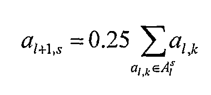
The pseudo symbols a]_ s and their pseudo prior information p {a± s) for each subset x" , where 1 = 1,...,L, s = 1,...,N]_, are defined as follows:
Figure imgf000015_0001
and as the 1-th level pseudo
Figure imgf000015_0007
symbol set. The set A]_ can also be decomposed into N]_+i subsets Af , such that
Figure imgf000015_0002
for m,n = 1,...,N1+1^ m ≠ n, for
Figure imgf000015_0004
1 = 1,...,L - 1.
The s-th element asM<=AM is also the centre of the elements in the corresponding subset:
Figure imgf000015_0005
or the 64QAM constellation, the above analysis therefore becomes:
Figure imgf000015_0003
and therefore
Figure imgf000015_0006
Figure imgf000016_0001
' and
A3 = {a3tl,...,a3A) As explained in de Jong et al. (1), the above partition produces squared subsets with minimum Euclidean distance. Using the multilevel structure of the 64QAM modulation, the selection step in SGA is decomposed into 3 steps where only 4M symbols are searched in each step. In the first step, all the third level pseudo symbols ψ3,v--,a3A} will be searched and some will be selected for next step. In the second step only 4M second level pseudo symbols which are related to the selected higher level ones are considered.
In the next step, if, in the previous step, α32 were selected, then only the pseudo symbols {Ω 2,3'α 2,4'Ω 2,7'α 2,8j are considered. In this step, only 4M symbols which are related to the selected second level ones are considered.
Then, in the next step,- if α23 were selected in the previous step, then only the symbols {a5,a6,aiS,a16} are considered. As a result, the number of computations is reduced from 64M to 12M via a multilevel strategy which will be explained below.
Similarly, a set of multilevel pseudo symbols can be constructed for 16QAM as shown in FIG. 5:
tf ={ak},k=1,.Λ6 I2 = { a]_ , a2 , a5 , ag } ,
Figure imgf000017_0001
= { 33 , a.% , a.η , ag } , ij n , ai2 , a]_5 , a]_ g } ,
Figure imgf000017_0002
For a multilevel sequential Gaussian approximation, the initial focus is on obtaining Θj for the j-th identification step. It should be noted that in the SGA algorithm, it is necessary to compute and sort MN likelihoods.
In contrast, with the multilevel structure of the N-QAM constellation, this step is decomposed further into 1 = log4N,...,l stages. At each stage, the M most significant pseudo symbol combinations are identified to obtain Θ',
Figure imgf000017_0003
for
1 = L,...,l.
Initially, the 4M approximated likelihoods ψm[xJtL) of all possible combinations of M elements in Θ^ , and four symbols in A^ are computed according to equation 5 as set out below. Then, the M most significant pseudo symbol combinations Θ' with the largest likelihoods ψm[xJiL) are selected. Then, the process moves down until the lowest modulation level 1 = 1 is reached.
It will be noted that, at each level 1, only 4M pseudo symbol combinations
Figure imgf000017_0004
are considered where x^eA'" such that the mean of the ele
Figure imgf000018_0002
for m = 1 , ..., M. At the last stage, where 1 = 1, the set of M most significant symbol combinations Θ;
Figure imgf000018_0001
is obtained.
FIG. 6 shows an example of the multilevel identification procedure, assuming that the symbols for antenna 1 have been identified as Θ]_ = {a3, a^5, a$r for M = 4 and 64QAM case. The multilevel
Figure imgf000018_0010
identification procedure is to be performed for the 2nc* antenna to obtain
Figure imgf000018_0009
Instead of computing and sorting 4 * 64 approximated likelihoods
Figure imgf000018_0008
for symbol combinations (a3, ai),..., (aβ, ag^, (a^5, a^),..., (a]_0fa64)' which would be required in the SGA algorithm, the MSGA algorithm only involves the computation and sorting of 4M approximated likelihoods for three steps as follows. For the first stage whe ies are calculated for
Figure imgf000018_0003
Figure imgf000018_0004
e
Figure imgf000018_0005
he next level (1 = 2), the 16 quantities are
Figure imgf000018_0006
10'x2,2) and 1^ will be
Figure imgf000018_0007
noted by the skilled practitioner, that a^ i is the mean of all elements in
Figure imgf000019_0001
and a3 2 i-s the mean of all the elements in h~ \ respectively .
Then the selection is repeated and 02= {(a3,a2 1), (a5'a2,l)' (a10'a2,l)' (a10'a2,4)ϊ is obtained.
Finally, the above calculation and selection procedure is again repeated in order to identify Θ2= {(a3,aχ), (a5,ag), (aio,ai), (a10'a7)ϊ-
The described multilevel approach involves the computation and sorting of 4M approximated likelihoods for log4N levels, which is only 1/2 and 3/16 of that of the selection procedure in the SGA algorithm for 16QAM and 64QAM modulation constellations respectively. The approach is exemplified below in general terms with reference to figure 8.
A. Initialization
In step Sl-2, the zero forcing output y, variance matrix Λ, the variance of the pseudo symbol alphabet A]_ Y]_, for 1 = 1, ..., log4N and the variance of A are computed as follows:
Figure imgf000019_0002
and the set of symbol combinations
Figure imgf000019_0004
is initialised as an empty set, with and L = log4N.
Figure imgf000019_0003
B. Multilevel identification step for j = l,...,Nτ In step Sl-4,
Figure imgf000020_0002
is computed according to equation (5) below for
Figure imgf000020_0003
anc^ m = l/».fM, then symbol combinations
Figure imgf000020_0004
are selected which have the largest ψm(xj L) f°r se"t
Figure imgf000020_0001
for j = l,...,Nrp. The vector e^ is, a column vector whose elements are all zeroes, but the k-th which is 1. 9l(*) means the real part of a complex number. [II"1 ] j j means the j-th diagonal element of matrix II]1.
It should be noted that the penalty term τσ?° is derived from Gaussian approximation to compensate the mismatching between the multilevel pseudo symbols Xj r j_ e A]_ and the actual transmitted symbols which takes value in A. a) For I = L - !,...,!, compute Ψm(χj,l) according to Eq . ( 5 ) , for Xj , l e A"' such that
Figure imgf000021_0003
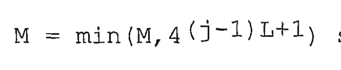
ItI = 1,...,M. b) Select the M =
Figure imgf000021_0004
symbol combinations which have the largest
Figure imgf000021_0005
C. Computation of marginal symbol probabilities for j = 1,...,NT
In step Sl-6, marginal symbol probabilities are computed for the symbols Xj .
1) For m = 1,...,M and Xj e A compute
Figure imgf000021_0002
) Compute the symbol probabilities for Xj e A,
Figure imgf000021_0001
In simulations of implementation of these methods, it has been observed that both of the algorithms achieve the near optical performance (Max-Log APP) where the complexity of Multilevel SGA is only around 70% and 30% of that of the original SGA algorithm for 16QAM and 64QAM modulation MIMO system (Nτ = NR = 4) respectively. This is illustrated in figure 7.
It will be appreciated that, in many circumstances, a wireless communications device will be provided with the facilities of a transmitter and a receiver in combination but, for this example, the devices have been illustrated as one way communications devices for reasons of simplicity.
The specific modulation scheme used in the illustrated example is not described, as the number of possible symbols, and the relationship between the symbols (which determines the manner in which symbols are distinguished) , are not relevant to the performance of this invention. However, it will be appreciated that the described embodiment can employ BPSK or QPSK, but also the present invention can be applied to higher order modulation schemes with little degradation of performance or computational complexity.
Whereas the present invention has been described with reference to a convolutional channel encoder, it will be appreciated that the invention can be implemented with regard to a stronger encoder such as a so-called turbo encoder (which includes an interleaver) .
While the present invention has been described in terms of hardware providing transmitter and receiver functions respectively, it will be appreciated that some, or all, of the apparatus to perform and/or provide the invention may be implemented by means of software directing the operation of a general purpose computer, perhaps suitably configured by hardware to establish wireless communication.
Software to provide implementation of the invention may be provided as a software product, to be loaded onto suitable apparatus to provide the invention. The software product may comprise a data carrier, which may include a magnetic storage device, e.g. a disk or tape, an optical storage device, e.g. an optical disk, for example a Compact Disk or DVD format, or a signal carrying data, e.g. from a storage location remotely accessed and in communication with a device to which the signal is directed, such as via the internet.

Claims

C L A I M S
1. A method of detecting information carried in a signal received from a transmission over a MIMO channel from a plurality of transmit antennas, the information being encoded as QAM symbols over space and time and/or frequency, the method comprising the steps of: arranging the available QAM symbols into a hierarchical tree structure, each level of the tree structure providing a greater level of granularity than the previous and, for each level of the tree structure from the least specific onwards: for each selected branch of the tree structure in said level, determining a branch likelihood measure, representing the approximated likelihood of a received signal containing a symbol in said branch, selecting one or more of said branches on the basis of their branch likelihood measures, said selected branches being selected for consideration in the next level of the tree structure; such that, at a last level, wherein each branch thereof corresponds to a symbol, said branch likelihood measure for a branch corresponds to a likelihood of said received signal containing the corresponding symbol .
2. A method in accordance with claim 1, wherein the step of determining a branch likelihood measure comprises determining the likelihood of said received signal containing a branch pseudo symbol, a branch pseudo symbol for a branch being a function of the symbols represented by said branch.
3. A method in accordance with claim 2, wherein a branch pseudo symbol is the mean of the symbols represented by said branch.
4. A method in accordance with any one of claims 1 to 3, wherein the step of selecting one or more branches comprises selecting a plurality of said branches, said plurality being less than the total number of branches under consideration.
5. A method in accordance with any one of claims 1 to 4, wherein the step of selecting comprises selecting branches having the highest branch likelihood measure of the branch likelihood measures determined in said determining step.
6. A method of communicating information in a MIMO system, comprising a transmitter having a plurality of transmit antennas and a receiver comprising a plurality of receive antennas, comprising encoding information as symbols, each symbol being a member of a set of permitted symbols, and transmitting the symbols at the transmit antennas modulated in accordance with space and time and/or frequency, then decoding the information at the receiver in accordance with the method of detecting information of any of claims 1 to 5.
7. A decoder for decoding information borne on a signal received from a transmission over a MIMO channel from a plurality of transmit antennas, the signal being received on a plurality of receive antennas, the information being encoded as a string of QAM symbols over space and time and/or frequency, comprising: means for storing a hierarchical tree structure of the available QAM symbols, each level of the tree structure providing a greater level of granularity than the previous: means for determining, for each level in the tree and for each selected branch of the tree structure in said level, a branch likelihood measure, representing the approximated likelihood of a received signal containing a symbol in said branch, and means for selecting one or more of said branches on the basis of their branch likelihood measures, said selected branches being selected for consideration in the next level of the tree structure; such that, at a last level, wherein each branch thereof corresponds to a symbol, said branch likelihood measure for a branch corresponds to a likelihood of said received signal containing the corresponding symbols, said selecting means thereby selecting one or more symbols for consideration and for determination of a likelihood measure.
8. A MIMO communications system, comprising a transmitter having a plurality of transmit antennas operable to encode information as symbols, each symbol being a member of a set of permitted symbols, and to transmitting the symbols at the transmit antennas modulated in accordance with space and time and/or frequency, and a receiver comprising a plurality of receive antennas, operable to decoding the information, and the receiver comprising a decoder in accordance with claim 7.
9. A computer program product storing computer readable instructions, operable to cause a general purpose computer communication apparatus to become configured to perform a method in accordance with any one of claims 1 to 6.
PCT/JP2007/064719 2006-07-21 2007-07-20 Decoder for wireless communication system Ceased WO2008010611A1 (en)

Priority Applications (1)

Application Number Priority Date Filing Date Title
JP2009503354A JP2009545190A (en) 2006-07-21 2007-07-20 Decoder for wireless communication system

Applications Claiming Priority (2)

Application Number Priority Date Filing Date Title
GB0614583.3 2006-07-21
GB0614583A GB2440382B (en) 2006-07-21 2006-07-21 Decoder for wireless communication system

Publications (1)

Publication Number Publication Date
WO2008010611A1 true WO2008010611A1 (en) 2008-01-24

Family

ID=36998547

Family Applications (1)

Application Number Title Priority Date Filing Date
PCT/JP2007/064719 Ceased WO2008010611A1 (en) 2006-07-21 2007-07-20 Decoder for wireless communication system

Country Status (6)

Country Link
US (1) US20080019428A1 (en)
EP (1) EP1881636A1 (en)
JP (1) JP2009545190A (en)
CN (1) CN101341679A (en)
GB (1) GB2440382B (en)
WO (1) WO2008010611A1 (en)

Citations (2)

* Cited by examiner, † Cited by third party
Publication number Priority date Publication date Assignee Title
US20050050072A1 (en) * 2003-09-03 2005-03-03 Lucent Technologies, Inc. Highly parallel tree search architecture for multi-user detection
US20050141644A1 (en) * 2003-12-31 2005-06-30 Sadowsky John S. Symbol de-mapping methods in multiple-input multiple-output systems

Family Cites Families (2)

* Cited by examiner, † Cited by third party
Publication number Priority date Publication date Assignee Title
US7822150B2 (en) * 2003-03-15 2010-10-26 Alcatel-Lucent Usa Inc. Spherical decoder for wireless communications
ATE443961T1 (en) * 2004-09-16 2009-10-15 Eth Zuerich METHOD AND DEVICE FOR DECODING A SIGNAL OF A MULTI-INPUT/MULTI-OUTPUT SYSTEM

Patent Citations (2)

* Cited by examiner, † Cited by third party
Publication number Priority date Publication date Assignee Title
US20050050072A1 (en) * 2003-09-03 2005-03-03 Lucent Technologies, Inc. Highly parallel tree search architecture for multi-user detection
US20050141644A1 (en) * 2003-12-31 2005-06-30 Sadowsky John S. Symbol de-mapping methods in multiple-input multiple-output systems

Non-Patent Citations (3)

* Cited by examiner, † Cited by third party
Title
DE JONG Y L C ET AL: "Iterative tree search detection for mimo wireless systems", VTC 2002-FALL. 2002 IEEE 56TH. VEHICULAR TECHNOLOGY CONFERENCE PROCEEDINGS. VANCOUVER, CANADA, SEPT. 24 - 28, 2002, IEEE VEHICULAR TECHNOLGY CONFERENCE, NEW YORK, NY : IEEE, US, vol. VOL. 1 OF 4. CONF. 56, 24 September 2002 (2002-09-24), pages 1041 - 1045, XP010608973, ISBN: 0-7803-7467-3 *
DE JONG Y L C ET AL: "Iterative trellis search detection for asynchronous MIMO systems", VEHICULAR TECHNOLOGY CONFERENCE, 2003. VTC 2003-FALL. 2003 IEEE 58TH ORLANDO, FL, USA 6-9 OCT. 2003, PISCATAWAY, NJ, USA,IEEE, US, 6 October 2003 (2003-10-06), pages 503 - 507Vol1, XP010700994, ISBN: 0-7803-7954-3 *
YUGANG JIA ET AL: "Joint channel tracking and symbol detection in mimo systems via multiple model methods", SIGNAL PROCESSING ADVANCES IN WIRELESS COMMUNICATIONS, 2005 IEEE 6TH WORKSHOP ON NEW YORK, NY, USA JUNE 2-8, 2005, PISCATAWAY, NJ, USA,IEEE, 2 June 2005 (2005-06-02), pages 12 - 16, XP010834301, ISBN: 0-7803-8867-4 *

Also Published As

Publication number Publication date
GB0614583D0 (en) 2006-08-30
CN101341679A (en) 2009-01-07
JP2009545190A (en) 2009-12-17
US20080019428A1 (en) 2008-01-24
EP1881636A1 (en) 2008-01-23
GB2440382B (en) 2008-07-09
GB2440382A (en) 2008-01-30

Similar Documents

Publication Publication Date Title
JP5529810B2 (en) Repetitive MIMO receiver using group-wise demapping
KR101124863B1 (en) Apparatus and method for processing communications from multiple sources
US7986752B2 (en) Parallel soft spherical MIMO receiver and decoding method
US7782984B2 (en) Method of sphere decoding with low complexity and good statistical output
US6757337B2 (en) Coding-assisted MIMO joint detection and decoding
EP1337082B1 (en) Receiver and method for multi-input multi-output iterative detection using feedback of soft estimates
EP1989790A2 (en) Apparatus, method and computer program product providing aimo receiver
EP1538773A2 (en) Nonsystematic repeat-accumulate codes for encoding and decoding information in a communication system
US20080123764A1 (en) Wireless communications apparatus
GB2395097A (en) A decoder apparatus and method of decoding therefor
US20070121753A1 (en) Wireless communications apparatus
JP4208874B2 (en) Decoder for multiplexed transmission system
US20060056550A1 (en) Receiver for use in a MIMO system
EP2597797B1 (en) Interference cancellation method with multiple data layer MIMO transmission
US7991082B2 (en) Maximum a posteriori probability decoder
JP2012522446A (en) Tree search method by depth-first search for detecting MIMO received signal
US20080019428A1 (en) Decoder for wireless communication system
US20090147887A1 (en) Method of calculating soft value and method of detecting transmission signal
US6584143B2 (en) Method and apparatus for joint detection of a coded signal in a CDMA system
WO2014198335A1 (en) Demodulation technique
GB2426419A (en) A hardware accelerator for a signal decoder
Lai et al. Complexity-Efficient Enumeration Techniques for Soft-Input, Soft-Output Sphere Decoding
Gamba Algorithms and architectures for the detection of MIMO signals
Chan et al. Iterative decoding for MIMO-BICM systems with an EM-based signal detector
accréditation conjointe avec l’Ecole et al. Algorithms and architectures for the detection of MIMO signals

Legal Events

Date Code Title Description
WWE Wipo information: entry into national phase

Ref document number: 200780000782.7

Country of ref document: CN

121 Ep: the epo has been informed by wipo that ep was designated in this application

Ref document number: 07768485

Country of ref document: EP

Kind code of ref document: A1

WWE Wipo information: entry into national phase

Ref document number: 2009503354

Country of ref document: JP

NENP Non-entry into the national phase

Ref country code: DE

NENP Non-entry into the national phase

Ref country code: RU

122 Ep: pct application non-entry in european phase

Ref document number: 07768485

Country of ref document: EP

Kind code of ref document: A1