WO2007004232A1 - Device management across firewall architecture - Google Patents
Device management across firewall architecture Download PDFInfo
- Publication number
- WO2007004232A1 WO2007004232A1 PCT/IN2005/000231 IN2005000231W WO2007004232A1 WO 2007004232 A1 WO2007004232 A1 WO 2007004232A1 IN 2005000231 W IN2005000231 W IN 2005000231W WO 2007004232 A1 WO2007004232 A1 WO 2007004232A1
- Authority
- WO
- WIPO (PCT)
- Prior art keywords
- agent
- snmp
- command
- remote host
- Prior art date
- Legal status (The legal status is an assumption and is not a legal conclusion. Google has not performed a legal analysis and makes no representation as to the accuracy of the status listed.)
- Ceased
Links
Classifications
-
- H—ELECTRICITY
- H04—ELECTRIC COMMUNICATION TECHNIQUE
- H04L—TRANSMISSION OF DIGITAL INFORMATION, e.g. TELEGRAPHIC COMMUNICATION
- H04L41/00—Arrangements for maintenance, administration or management of data switching networks, e.g. of packet switching networks
- H04L41/02—Standardisation; Integration
- H04L41/0246—Exchanging or transporting network management information using the Internet; Embedding network management web servers in network elements; Web-services-based protocols
- H04L41/026—Exchanging or transporting network management information using the Internet; Embedding network management web servers in network elements; Web-services-based protocols using e-messaging for transporting management information, e.g. email, instant messaging or chat
-
- H—ELECTRICITY
- H04—ELECTRIC COMMUNICATION TECHNIQUE
- H04L—TRANSMISSION OF DIGITAL INFORMATION, e.g. TELEGRAPHIC COMMUNICATION
- H04L41/00—Arrangements for maintenance, administration or management of data switching networks, e.g. of packet switching networks
- H04L41/02—Standardisation; Integration
- H04L41/0246—Exchanging or transporting network management information using the Internet; Embedding network management web servers in network elements; Web-services-based protocols
- H04L41/0266—Exchanging or transporting network management information using the Internet; Embedding network management web servers in network elements; Web-services-based protocols using meta-data, objects or commands for formatting management information, e.g. using eXtensible markup language [XML]
-
- H—ELECTRICITY
- H04—ELECTRIC COMMUNICATION TECHNIQUE
- H04L—TRANSMISSION OF DIGITAL INFORMATION, e.g. TELEGRAPHIC COMMUNICATION
- H04L51/00—User-to-user messaging in packet-switching networks, transmitted according to store-and-forward or real-time protocols, e.g. e-mail
- H04L51/07—User-to-user messaging in packet-switching networks, transmitted according to store-and-forward or real-time protocols, e.g. e-mail characterised by the inclusion of specific contents
- H04L51/18—Commands or executable codes
-
- H—ELECTRICITY
- H04—ELECTRIC COMMUNICATION TECHNIQUE
- H04L—TRANSMISSION OF DIGITAL INFORMATION, e.g. TELEGRAPHIC COMMUNICATION
- H04L63/00—Network architectures or network communication protocols for network security
- H04L63/02—Network architectures or network communication protocols for network security for separating internal from external traffic, e.g. firewalls
- H04L63/029—Firewall traversal, e.g. tunnelling or, creating pinholes
-
- H—ELECTRICITY
- H04—ELECTRIC COMMUNICATION TECHNIQUE
- H04L—TRANSMISSION OF DIGITAL INFORMATION, e.g. TELEGRAPHIC COMMUNICATION
- H04L41/00—Arrangements for maintenance, administration or management of data switching networks, e.g. of packet switching networks
- H04L41/28—Restricting access to network management systems or functions, e.g. using authorisation function to access network configuration
-
- H—ELECTRICITY
- H04—ELECTRIC COMMUNICATION TECHNIQUE
- H04L—TRANSMISSION OF DIGITAL INFORMATION, e.g. TELEGRAPHIC COMMUNICATION
- H04L63/00—Network architectures or network communication protocols for network security
- H04L63/04—Network architectures or network communication protocols for network security for providing a confidential data exchange among entities communicating through data packet networks
- H04L63/0428—Network architectures or network communication protocols for network security for providing a confidential data exchange among entities communicating through data packet networks wherein the data content is protected, e.g. by encrypting or encapsulating the payload
Definitions
- the present invention generally relates to device management across a firewall, and more particularly relates to managing a device within a local area network (LAN) coupled to a firewall from a host located outside the firewall.
- LAN local area network
- Computer data processing systems often include a group of peripheral devices, such as printers, fax machines, plotters, projectors and the like, that are connected to a LAN.
- peripheral devices such as printers, fax machines, plotters, projectors and the like
- all of these peripheral devices are network enabled and allow configuring operating parameters and monitor their performance locally.
- These peripheral devices are usually rich in features and are SNMP (simple network management protocol) enabled. Hence, they can be managed using SNMP managers with the LAN running a TCP/IP (transmission control protocol/Internet protocol). Typically, these devices get connected to the LAN within a corporate network.
- TCP/IP transmission control protocol/Internet protocol
- firewalls have become a single point of network access where traffic can be analyzed and controlled according to parameters such as applications, address, and user, for both incoming traffic from remote users and outgoing traffic to the Internet. Consequently, peripheral devices located within a local computer data processing system that is protected by a firewall cannot be unconditionally accessed from a remote location.
- Controlling these peripheral devices from outside the firewall requires opening the firewall, which can require organizational level IT approval and is typically not a desired practice amongst organizations.
- the software controlling these peripheral devices becomes increasingly sophisticated and complex. Installation, troubleshooting, configuring, and monitoring of these peripheral devices often can be difficult, time consuming, and can require specialized knowledge of the peripheral devices.
- the firewall would prevent devices, such as digital projects located within the firewall from firmware upgrade, monitoring the bulb life, monitoring the fan condition and so on by the remote host. Therefore, it would be desirable to outsource such tasks, to a managed service industry that is remotely located, to . reduce costs. This requires the managed service industry to have access to the computer system that is protected by a firewall.
- a method for managing one or more devices via an agent that is within a firewall and a local network by a remote host located outside the firewall including the steps of sending an Email including a desired command and a payload from the remote host, wherein the Email includes a payload data unit (PDU) as defined by an Email device management protocol
- PDU payload data unit
- EDMP receiving the Email from the remote host by the agent, parsing the received Email by the agent, reading the parsed Email by the agent, initiating an action by creating an SNMP command to be performed on one of the one or more devices by the agent as a function of the parsed Email.
- FIG. 1 is a flowchart illustrating an example method of a host initiated command to manage a device located across a firewall according to an embodiment of the present invention.
- FIG. 2 is a flowchart illustrating an example method of receiving the host initiated command by an agent to manage a device located within a LAN and across a firewall according to an embodiment of the present invention.
- FIG. 3 is a flowchart illustrating an example method of an agent initiated command to communicate with the host located across a firewall according to an embodiment of the present invention.
- FIG. 4 is a block diagram illustrating a device management architecture that may be employed according to various embodiments of the present invention shown in FIGS. 1-3.
- FIG. 5 is a block diagram illustrating example remote host architecture according to an embodiment of the present invention shown in FIG. 4.
- FIG. 6 is a block diagram illustrating an example agent architecture according to an embodiment of the present invention shown in FIG. 4.
- FIG. 7 is a block diagram of a typical computer system used for implementing embodiments of the present subject matter shown in FIGS. 1-6.
- Email refers to electronic mail, which is the transmission of a message over communication networks.
- messages here refers to an EDMP (Email device management protocol) created either by a remote host or an agent located across a firewall for communication between the remote host and the agent via the firewall.
- EDMP-PDU refers to a PDU that is formed as defined by the EDMP.
- remote host refers to a device management station located anywhere outside the firewall.
- FIG. 1 illustrates an example method 100 of a remote host communicating with a device located across a firewall and within a LAN.
- this example method 100 begins by building a desired command and attaching an EDMP-PDU to communicate with a device located across a firewall by a remote host.
- Exemplary devices include fax machines, printers, plotters, projectors, and the like.
- the formed command including the payload is converted to formats, such as XML, HTML, delimited text, binary packet and so on.
- the following table illustrates some example commands including payloads that may be formed using the XML format to communicate with a device, such as a projector located within a LAN and coupled to a firewall.
- an Email including a EDMP-PDU an Email device management protocol (EDMP) that uses known Email protocols, such as SMTP (simple mail transfer protocol), a POP3 (post office protocol 3), or a IMAP (Internet mail access protocol) is created.
- the EDMP includes the converted command and the PDU, such as an agent ID.
- the EDMP defines a way of sending the command, receiving the response, and also the device initiated alarms using Email as a transport mechanism.
- the PDU includes an agent ID (identification), a target ID, a command, data, and a unique token.
- the unique token is used for tracking the commands and responses to ensure completeness of the management operation initiated by the user.
- Exemplary PDU data includes information, such as device IP (internet protocol) address, device name, device specific parameters and its associated values, device firmware necessary to upgrade a device and the like.
- the EDMP provides the ability to communicate between the agent residing in a LAN within an organization, such as a corporation's firewall and the management stations, residing in a remote host outside the firewall. In these embodiments, the EDMP has the capability to send and receive commands and data from the agent to the management station across the firewall.
- the Email based communication is generally asynchronous in nature, i.e., the command sent and the result received in response to the command sent are separated by a latency introduced by the Email, SMTP, and processing at the agent.
- the EDMP has a built in session manager that maintains a list of commands sent to agents that are coupled to the remote host. Li these embodiments, the session manager issues a time stamp based unique token to all the commands that are built and sent to an agent located across the firewall.
- each of the commands created using the above technique carries a unique token along with the PDU. The results generated against these commands return these unique tokens.
- the session manager verifies the received unique token and associate it with the command sent.
- the process is termed complete when the unique token matches with one of the commands that were sent from the remote host. Also in these embodiments, there is a time-out period for receiving the result and hence the unique tokens are sent. If this time out period elapses, the session manager resends the command with the same unique token. In an instance where both the results (i.e., the one sent earlier and the one sent after the time-out period) are received by the agent including the same unique token, the first sent result is considered and the second result including the unique token is rejected by the agent.
- the unique token is generated by the remote host upon a user performing a management operation on a digital projector, such as setting brightness, checking for contrast value or device firmware version and so on.
- An Email is then formed by the remote host using the Email command, the payload, and the unique token.
- the created Email is encrypted.
- the encrypted Email is sent using an Email service.
- the Email is sent using the SMTP protocol.
- the protocol used to send the Email depends on the type ' of Email exchange server used to send the Email.
- the EDMP includes a set of commands formed described above. Each of these commands have an associated structure and a PDU. These commands are built using a format, such as XML, HTML and the like.
- a Email including the commands are dispatched to agent located within a firewall using SMTP.
- the Email is retrieved using POP3 and/or IMAP protocols. The agent then extracts the commands and executes the operation.
- the agent receives the SNMP traps sent by each of the one or more devices.
- the agent extracts the alerts associated with each of the SNMP traps and forms associated return EDMP-PDU.
- the agent then forms an Email including the return EDMP-PDU and sends them across the firewall to the remote host.
- FIG. 2 illustrates an example method 200 of receiving a host initiated command by an agent to manage a device within a LAN.
- this example method 200 begins by receiving the encrypted Email from the remote host by the agent that is within the firewall.
- the received encrypted Email is decrypted by the agent.
- the agent parses the decrypted Email and reads the parsed Email including the command, the PDU, and the unique token.
- the agent stores the read unique token upon parsing the Email.
- the agent then sends an acknowledgement of the receipt of the Email to the remote host.
- the remote host then resends the Email upon not receiving an acknowledgement from the agent within a predetermined amount of time of sending the Email.
- the agent verifies the receipt of the resent Email as a function of the stored unique token.
- the agent rejects the resent Email if the unique token received is already stored by the agent upon parsing an earlier received Email.
- the agent initiates an action by creating an SNMP command to be performed on the one of one or more devices coupled within the LAN as a function of the received Email including the EDMP.
- the agent creates a SNMP trap using the parsed Email, i.e., the parsed EDMP.
- the agent creates a SNMP command as a function of the parsed Email.
- the agent sends the created SNMP trap to an associated one of the one or more devices coupled to the agent within the LAN.
- one of the one or more devices receives the SNMP command from the agent.
- the one of the one or more devices then creates a SNMP response, upon receiving the SNMP command from the agent and completion of the action as a function of the received SNMP command, and sends it to the agent.
- the agent receives the SNMP response from the one of the one or more devices.
- the agent creates an Email including a return EDMP-PDU.
- the return EDMP-PDU includes information associated with the received SNMP response.
- the Email created by the agent includes the EDMP-PDU which comprises an event generated by the one of the one or more devices and/or a response generated as a function of the SNMP response and PDU.
- the agent sends the Email including the return EDMP-PDU formed as a function of the received SNMP response to the remote host.
- the following table illustrates some example Email including return EDMP-PDU formed and communicated by the agent to the remote host upon receiving the SNMP response from the one or more devices, such as a projector coupled to the agent within a LAN coupled to a firewall.
- FIG. 3 illustrates an example method 300 of one of the one or more devices communicating with the agent within a LAN.
- this example method 300 begins by sending an alert SNMP trap from the one of the one or more devices to the agent.
- the method 300 begins by sending a SNMP response from the one of the one or more devices to the agent.
- the agent receives the alert SNMP trap from the one of the one or more devices.
- the agent then creates an Email including an EDMP-PDU that is formed based on the alert SNMP trap received from the one of the one or more devices.
- the result can be an acknowledgement received from the one or more devices.
- the agent then sends for the created Email including the alert EDMP-PDU to the remote host.
- the following table illustrates some example Email including the alert EDMP-PDU formed and communicated by the agent to the remote host upon receiving the an alert SNMP trap from the one or more devices, such as a projector coupled to the agent within a LAN coupled to a firewall.
- FIG. 4 is a block diagram 400 of example device management architecture for implementing the methods, illustrated in example flowcharts 100-300 shown in FIGS 1-3, for a host to communicate with one or more devices located across a firewall.
- the block diagram 400 shown in FIG. 4 includes a remote host 410 communicatively coupled to an organizational computer network 415 via a firewall 420.
- the organizational computer network 415 includes one or more agents 430 and associated one or more LAN enabled devices 440 that are coupled to each of the one or more agents 430.
- each of the one or more agents 430 are coupled to the remote host 410 via the firewall 420.
- Exemplary LAN enabled devices 440 include printers, fax machines, plotters, projectors and the like.
- one of the one or more agents 430 receives the Email including an EDMP-PDU that uses SMTP as a transport mechanism.
- the one of the one or more agents 430 divides the received Email and reads the parced Email and initiates an action by creating an SNMP command to manage/communicate with the one or more LAN enabled devices 440 as a function of the parsed Email.
- the action includes tasks, such as SNMP get, set, start discovery, and store configurations.
- FIG. 5 is a block diagram 500 of example remote host architecture for implementing the method of a remote host communicating with an agent located across a firewall shown in FIG. 1.
- the block diagram 500 shown in FIG. 5 includes a host command builder 510, a host dispatcher 520, and a host Email service module 530.
- builds a desired command by attaching an EDMP-PDU and a unique token to the desired command.
- the host command builder 510 then converts the desired command to an XML format.
- the host dispatcher 520 then creates an Email which includes the EDMP-PDU along with the unique token in the XML format.
- the PDU can include device and agent specific parameters, such as agent's email ID, device ID, command, and device specific parameter and its associated values.
- the host Email service module 530 then dispatches the Email across the firewall 420 using the SMTP transport mechanism.
- FIG. 6 is a block diagram 600 of example agent architecture for implementing the method, of an agent communicating with a remote host located across a firewall and one or more devices within a LAN, shown in FIGS. 2-3.
- the block diagram 600 includes an agent Email service module 610, an agent command parser 620, an agent translate module 630, an agent command builder 640, and an agent dispatcher 650.
- the agent Email service module 610 receives the Email including the EDMP- PDU along with the unique token from the host Email service module 530 (shown in FIG. 5) via the firewall 420 (shown in FIG. 4).
- the agent command parser 620 then receives the Email from the agent Email service module 610 and parses the received Email and reads the parsed Email including the EDMP-PDU and the unique token.
- the agent command parser 620 then initiates an action by creating an SNMP command to be performed on the one of the one or more LAN enabled devices as a function of the parsed and read EDMP- PDU and the unique token.
- the agent translate module 630 then extracts the desired command upon parsing the Email including the EDMP-PDU and translates the parsed
- the agent Email service module 610 sends the translated SNMP command to the one of the one or more LAN enabled devices 440 (shown in FIG.
- the agent command builder 640 receives a result upon completion of the action associated with the SNMP command sent by the agent Email service module 610 and forms a SNMP response.
- the agent dispatcher 650 then receives the SNMP response and sends it to the Email service module 610.
- the Email service module 610 then forms a return EDMP-PDU and sends it to the remote host 410 via the firewall 420 (shown in FIG. 4).
- the one of the one or more LAN enabled devices 440 then extracts information associated with the SNMP command and creates any associated alert SNMP traps upon registering the SNMP command received from the agent 430.
- the agent command builder 640 then receives the associated alert SNMP traps from the one of the one or more LAN enabled devices 440 (shown in FIG. 4) and forms the SNMP response and passes it to the agent dispatcher 650.
- the agent dispatcher 650 then sends the SNMP response including the alert SNMP traps to the agent Email service module 610.
- the agent Email service module 610 forms the return EDMP-PDU and send sit to the remote host 420 via the firewall 410 (shown in FIG. 4).
- the operation of the device management architecture 400 shown in FIG. 4 is explained in more detail with reference to flowcharts 100-300 shown in FIGS. 1-3.
- FIG. 7 Various embodiments of the present subject matter can be implemented in software, which may be run in the environment shown in FIG. 7 (to be described below) or in any other suitable computing environment.
- the embodiments of the present subject matter are operable in a number of general-purpose or special-purpose computing environments.
- Some computing environments include personal computers, general-purpose computers, server computers, hand-held devices (including, but not limited to, telephones and personal digital assistants (PDAs) of all types), laptop devices, multi-processors, microprocessors, set-top boxes, programmable consumer electronics, network computers, minicomputers, mainframe computers, distributed computing environments and the like to execute code stored on a computer-readable medium.
- PDAs personal digital assistants
- FIG. 7 shows an example of a suitable computing system environment for implementing embodiments of the present subject matter.
- FIG. 7 and the following discussion are intended to provide a brief, general description of a suitable computing environment in which certain embodiments of the inventive concepts contained herein may be implemented.
- a general computing device in the form of a computer 710, may include a processing unit 702, memory 704, removable storage 701, and non-removable storage 714.
- Computer 710 additionally includes a bus 705 and a network interface (NI) 712.
- NI network interface
- Computer 710 may include or have access to a computing environment that includes one or more user input modules 716, one or more output modules 718, and one or more communication connections 720 such as a network interface card or a USB connection.
- the one or more output devices 718 can be a display device of computer, computer monitor, TV screen, plasma display, LCD display, display on a digitizer, display on an electronic tablet, and the like.
- the computer 710 may operate in a networked environment using the communication connection 720 to connect to one or more remote computers.
- a remote computer may include a personal computer, server, router, network PC, a peer device or other network node, and/or the like.
- the communication connection may include a LAN, a Wide Area Network (WAN), and/or other networks.
- WAN Wide Area Network
- the memory 704 may include volatile memory 706 and non- volatile memory 708.
- volatile memory 706 and non- volatile memory 708 A variety of computer-readable media may be stored in and accessed from the memory elements of computer 710, such as volatile memory 706 and non- volatile memory 708, removable storage 701 and non-removable storage 714.
- Computer memory elements can include any suitable memory device(s) for storing data and machine-readable instructions, such as read only memory (ROM), random access memory (RAM), erasable programmable read only memory (EPROM), electrically erasable programmable read only memory
- processor or “processing unit,” as used herein, means any type of computational circuit, such as, but not limited to, a microprocessor, a microcontroller, a complex instruction set computing (CISC) microprocessor, a reduced instruction set computing (RISC) microprocessor, a very long instruction word (VLIW) microprocessor, explicitly parallel instruction computing (EPIC) microprocessor, a graphics processor, a digital signal processor, or any other type of processor or processing circuit.
- CISC complex instruction set computing
- RISC reduced instruction set computing
- VLIW very long instruction word
- EPIC explicitly parallel instruction computing
- graphics processor a digital signal processor, or any other type of processor or processing circuit.
- the term also includes embedded controllers, such as generic or programmable logic devices or arrays, application specific integrated circuits, single-chip computers, smart cards, and the like.
- Embodiments of the present subject matter may be implemented in conjunction with program modules, including functions, procedures, data structures, application programs, etc., for performing tasks, or defining abstract data types or low-level hardware contexts.
- a program module 725 may include machine-readable instructions capable of managing one or more peripheral devices located across a firewall according to the teachings and herein described embodiments of the present subject matter.
- the program module 725 may be included on a CD-ROM and loaded from the CD-ROM to a hard drive in nonvolatile memory 708.
- the machine-readable instructions cause the computer 710 to provide an integrated platform according to the various embodiments of the present subject matter.
- the program module 725 includes commands to manage one or more devices located across a firewall according to various embodiments of the present invention.
- the operation of the computer system 700 to provide a device management architecture is explained in more detail with reference to FIGS. 1-6.
- This technique provides device management solutions that work within a LAN.
- the EDMP-PDU and the return EDMP-PDU described above enables the management of devices outside a firewall.
- the devices located within a firewall can be managed using a remote host located outside the firewall. This includes setting device properties and also receiving alerts associated with the SNMP traps generated by each of devices, such as digital projectors, printers, and so on.
- the above described technique facilitates managed service provides to manage devices located within a firewall via the remote host using the Email including the EDMPs.
- the technique offers a new opportunity for managed service providers to manager devices, such as projects, printers, plotters, and other such network devices and elements.
- manager devices such as projects, printers, plotters, and other such network devices and elements.
- the EDMP can be used and extended for any communication across the firewall.
- the present subject matter can be implemented in a number of different embodiments, including various methods, a circuit, an I/O device, a system, and an article comprising a machine-accessible medium having associated instructions.
- FIGS. 1-7 are merely representational and are not drawn to scale. Certain proportions thereof may be exaggerated, while others may be minimized. FIGS. 1-7 illustrate various embodiments of the subject matter that can be understood and appropriately carried out by those of ordinary skill in the art.
Landscapes
- Engineering & Computer Science (AREA)
- Computer Networks & Wireless Communication (AREA)
- Signal Processing (AREA)
- Computer Hardware Design (AREA)
- Computer Security & Cryptography (AREA)
- Computing Systems (AREA)
- General Engineering & Computer Science (AREA)
- Data Exchanges In Wide-Area Networks (AREA)
Abstract
A technique that provides device management network for managing one or more devices located across a firewall. In one example embodiment, this is achieved by sending an Email, including an EDMP-PDU that uses SMTP, POP3, and/or IMAP as a transport mechanism, by a remote host. The Email sent by the remote host is then received by an agent as the firewall is configured to allow the Email. The agent then parses the received Email and reads it. The agent then initiates an action by creating an SNMP command, to be performed on one of the one or more devices, as a function of the parsed Email.
Description
DEVICE MANAGEMENT ACROSS FIREWALL ARCHITECTURE
Technical Field of the Invention
The present invention generally relates to device management across a firewall, and more particularly relates to managing a device within a local area network (LAN) coupled to a firewall from a host located outside the firewall.
Background of the Invention
Computer data processing systems often include a group of peripheral devices, such as printers, fax machines, plotters, projectors and the like, that are connected to a LAN. In general, all of these peripheral devices are network enabled and allow configuring operating parameters and monitor their performance locally. These peripheral devices are usually rich in features and are SNMP (simple network management protocol) enabled. Hence, they can be managed using SNMP managers with the LAN running a TCP/IP (transmission control protocol/Internet protocol). Typically, these devices get connected to the LAN within a corporate network.
Generally, these peripheral devices are protected from external world using the standard firewall technologies. For purposes of security and system integrity, many organizations install firewall that restricts the exchange of information with computers located outside of the organization. Typically, such a firewall is interposed between a local computer data processing system and the Internet to block undesired incoming requests and information. In effect, firewalls have become a single point of network access where traffic can be analyzed and controlled according to parameters such as applications, address, and user, for both incoming traffic from remote users and outgoing traffic to the Internet. Consequently, peripheral devices located within a local computer data processing system that is protected by a firewall cannot be unconditionally accessed from a remote location. Controlling these peripheral devices from outside the firewall requires opening the firewall, which can require organizational level IT approval and is typically not a desired practice amongst organizations. In general, as features and conveniences offered by these peripheral devices are enhanced, the software controlling these peripheral devices becomes increasingly
sophisticated and complex. Installation, troubleshooting, configuring, and monitoring of these peripheral devices often can be difficult, time consuming, and can require specialized knowledge of the peripheral devices. For example, the firewall would prevent devices, such as digital projects located within the firewall from firmware upgrade, monitoring the bulb life, monitoring the fan condition and so on by the remote host. Therefore, it would be desirable to outsource such tasks, to a managed service industry that is remotely located, to . reduce costs. This requires the managed service industry to have access to the computer system that is protected by a firewall.
Summary of the Invention
According to an aspect of the subject matter, there is provided a method for managing one or more devices via an agent that is within a firewall and a local network by a remote host located outside the firewall, the method including the steps of sending an Email including a desired command and a payload from the remote host, wherein the Email includes a payload data unit (PDU) as defined by an Email device management protocol
(EDMP), receiving the Email from the remote host by the agent, parsing the received Email by the agent, reading the parsed Email by the agent, initiating an action by creating an SNMP command to be performed on one of the one or more devices by the agent as a function of the parsed Email.
Brief Description of the Drawings
Embodiments of the invention will now be described, by way of example only, with reference to the accompanying drawings in which:
FIG. 1 is a flowchart illustrating an example method of a host initiated command to manage a device located across a firewall according to an embodiment of the present invention.
FIG. 2 is a flowchart illustrating an example method of receiving the host initiated command by an agent to manage a device located within a LAN and across a firewall according to an embodiment of the present invention.
FIG. 3 is a flowchart illustrating an example method of an agent initiated command to communicate with the host located across a firewall according to an embodiment of the present invention.
FIG. 4 is a block diagram illustrating a device management architecture that may be employed according to various embodiments of the present invention shown in FIGS. 1-3.
FIG. 5 is a block diagram illustrating example remote host architecture according to an embodiment of the present invention shown in FIG. 4.
FIG. 6 is a block diagram illustrating an example agent architecture according to an embodiment of the present invention shown in FIG. 4.
FIG. 7 is a block diagram of a typical computer system used for implementing embodiments of the present subject matter shown in FIGS. 1-6.
Detailed Description of the Invention
In the following detailed description of the various embodiments of the invention, reference is made to the accompanying drawings that form a part hereof, and in which are shown by way of illustration specific embodiments in which the invention may be practiced. These embodiments are described in sufficient detail to enable those skilled in the art to practice the invention, and it is to be understood that other embodiments may be utilized and that changes may be made without departing from the scope of the present invention. The following detailed description is, therefore, not to be taken in a limiting sense, and the scope of the present invention is defined only by the appended claims. Also, the terms "SMTP" and "SMTP protocol" are used interchangeably throughout the document. Further, the terms "host" and "remote host" are used interchangeably through the document. Furthermore, the term "Email" refers to electronic mail, which is the transmission of a message over communication networks. In addition, the term "message"
here refers to an EDMP (Email device management protocol) created either by a remote host or an agent located across a firewall for communication between the remote host and the agent via the firewall. Moreover, the term "EDMP-PDU" refers to a PDU that is formed as defined by the EDMP. The term "remote host" refers to a device management station located anywhere outside the firewall.
FIG. 1 illustrates an example method 100 of a remote host communicating with a device located across a firewall and within a LAN. At step 110, this example method 100 begins by building a desired command and attaching an EDMP-PDU to communicate with a device located across a firewall by a remote host. Exemplary devices include fax machines, printers, plotters, projectors, and the like. At step 120, the formed command including the payload is converted to formats, such as XML, HTML, delimited text, binary packet and so on.
The following table illustrates some example commands including payloads that may be formed using the XML format to communicate with a device, such as a projector located within a LAN and coupled to a firewall.


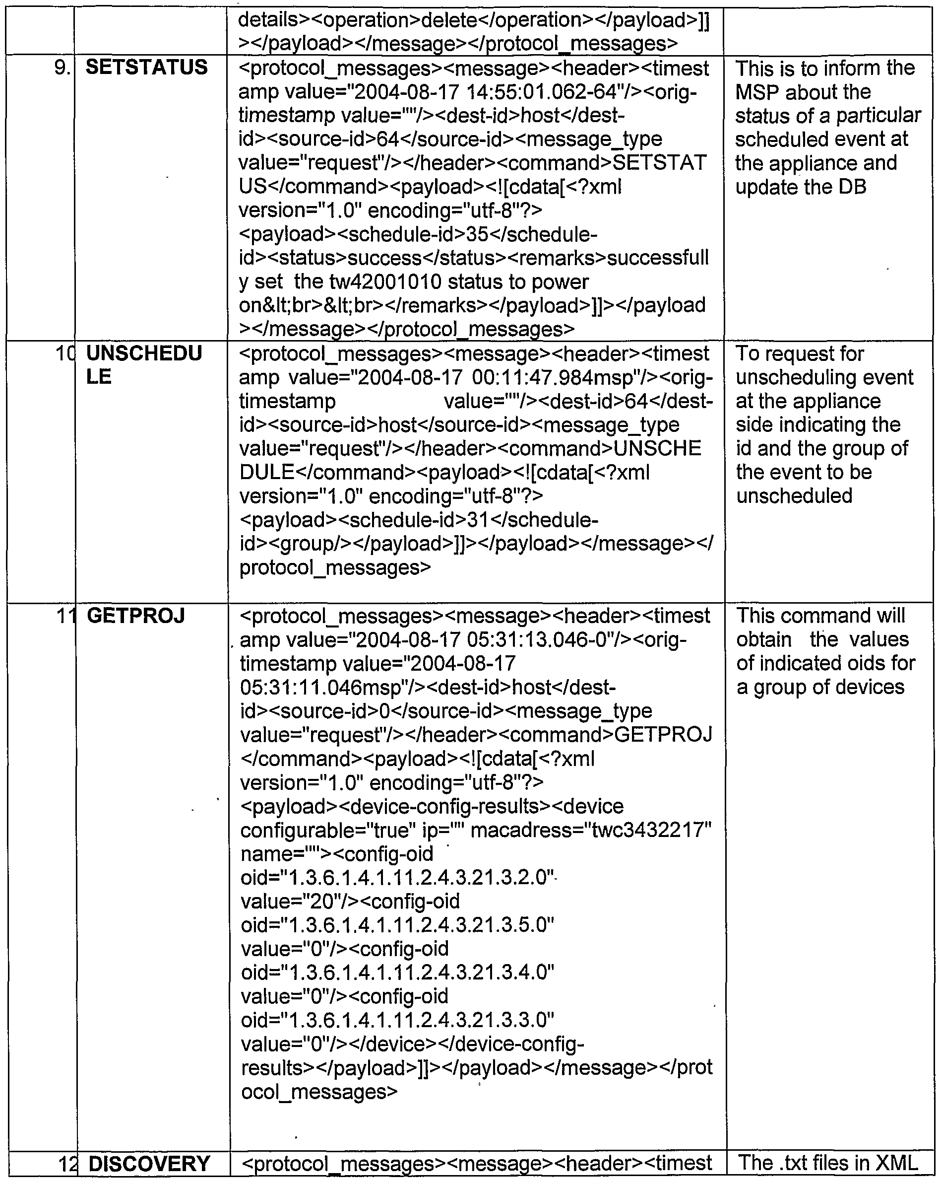

At step 130, an Email including a EDMP-PDU an Email device management protocol (EDMP) that uses known Email protocols, such as SMTP (simple mail transfer protocol), a POP3 (post office protocol 3), or a IMAP (Internet mail access protocol) is created. In these embodiments, the EDMP includes the converted command and the PDU, such as an agent ID. The EDMP defines a way of sending the command, receiving the response, and also the device initiated alarms using Email as a transport mechanism.
In some embodiments, the PDU includes an agent ID (identification), a target ID, a command, data, and a unique token. The unique token is used for tracking the commands and responses to ensure completeness of the management operation initiated by the user. Exemplary PDU data includes information, such as device IP (internet protocol) address, device name, device specific parameters and its associated values, device firmware necessary to upgrade a device and the like. The EDMP provides the ability to communicate between the agent residing in a LAN within an organization, such as a corporation's firewall and the management stations, residing in a remote host outside the firewall. In these embodiments, the EDMP has the capability to send and receive commands and data from the agent to the management station across the firewall. The Email based communication is generally asynchronous in nature, i.e., the command sent and the result received in response to the command sent are separated by a latency introduced by the Email, SMTP, and processing at the agent. In order to increase the reliability, the EDMP has a built in session manager that maintains a list of commands sent to agents that are coupled to the remote host. Li these embodiments, the session manager issues a time stamp based unique token to all the commands that are built and sent to an agent located across the firewall.
In these embodiments, each of the commands created using the above technique carries a unique token along with the PDU. The results generated against these commands return these unique tokens. The session manager verifies the received unique token and associate it with the command sent. The process is termed complete when the unique token matches with one of the commands that were sent from the remote host. Also in these embodiments, there is a time-out period for receiving the result and hence the unique tokens are sent. If this time out period elapses, the session manager resends the command with the same unique token. In an instance where both the results (i.e., the one sent earlier and the one sent after the time-out period) are received by the agent including the same unique token, the first sent result is considered and the second result including the unique token is rejected by the agent.
In some embodiments, the unique token is generated by the remote host upon a user performing a management operation on a digital projector, such as setting brightness, checking for contrast value or device firmware version and so on. An Email is then formed by the remote host using the Email command, the payload, and the unique token.
At step 140, the created Email is encrypted. At step 150, the encrypted Email is sent using an Email service. In these embodiments, the Email is sent using the SMTP protocol. Generally, the protocol used to send the Email depends on the type' of Email exchange server used to send the Email. The EDMP includes a set of commands formed described above. Each of these commands have an associated structure and a PDU. These commands are built using a format, such as XML, HTML and the like. A Email including the commands are dispatched to agent located within a firewall using SMTP. At the agent side the Email is retrieved using POP3 and/or IMAP protocols. The agent then extracts the commands and executes the operation. Also in these embodiments, the agent receives the SNMP traps sent by each of the one or more devices. The agent then extracts the alerts associated with each of the SNMP traps and forms associated return EDMP-PDU. The agent then forms an Email including the return EDMP-PDU and sends them across the firewall to the remote host.
FIG. 2 illustrates an example method 200 of receiving a host initiated command by an agent to manage a device within a LAN. At step 210, this example method 200 begins by receiving the encrypted Email from the remote host by the agent that is within the firewall. At step 220, the received encrypted Email is decrypted by the agent. At step 230, the agent parses the decrypted Email and reads the parsed Email including the command, the PDU, and the unique token. In some embodiments, the agent stores the read unique token upon parsing the Email. As explained earlier with reference to FIG. 1, the agent then sends an acknowledgement of the receipt of the Email to the remote host. In these embodiments, the remote host then resends the Email upon not receiving an acknowledgement from the agent within a predetermined amount of time of sending the Email. The agent verifies the receipt of the resent Email as a function of the stored unique token. The agent rejects the resent Email if the unique token received is already stored by the agent upon parsing an earlier received Email.
At step 240, the agent initiates an action by creating an SNMP command to be performed on the one of one or more devices coupled within the LAN as a function of the received Email including the EDMP. In these embodiments, the agent creates a SNMP trap using the parsed Email, i.e., the parsed EDMP. In some embodiments, the agent creates a SNMP command as a function of the parsed Email. Also in these embodiments, the agent sends the created SNMP trap to an associated one of the one or more devices coupled to the agent within the LAN.
At step 250, one of the one or more devices receives the SNMP command from the agent. The one of the one or more devices then creates a SNMP response, upon receiving the SNMP command from the agent and completion of the action as a function of the received SNMP command, and sends it to the agent. At step 260, the agent receives the SNMP response from the one of the one or more devices.
At step 270, the agent creates an Email including a return EDMP-PDU. The return EDMP-PDU includes information associated with the received SNMP response. In these embodiments, the Email created by the agent includes the EDMP-PDU which comprises an
event generated by the one of the one or more devices and/or a response generated as a function of the SNMP response and PDU. At step 280, the agent sends the Email including the return EDMP-PDU formed as a function of the received SNMP response to the remote host.
The following table illustrates some example Email including return EDMP-PDU formed and communicated by the agent to the remote host upon receiving the SNMP response from the one or more devices, such as a projector coupled to the agent within a LAN coupled to a firewall.


FIG. 3 illustrates an example method 300 of one of the one or more devices communicating with the agent within a LAN. At step 310, this example method 300 begins by sending an alert SNMP trap from the one of the one or more devices to the agent. In some embodiments, the method 300 begins by sending a SNMP response from the one of the one or more devices to the agent.
At step 320, the agent receives the alert SNMP trap from the one of the one or more devices. At step 330, the agent then creates an Email including an EDMP-PDU that is formed based on the alert SNMP trap received from the one of the one or more devices. The result can be an acknowledgement received from the one or more devices. At step 340,
the agent then sends for the created Email including the alert EDMP-PDU to the remote host.
The following table illustrates some example Email including the alert EDMP-PDU formed and communicated by the agent to the remote host upon receiving the an alert SNMP trap from the one or more devices, such as a projector coupled to the agent within a LAN coupled to a firewall.

Although the flowcharts 100, 200, and 300 includes steps 110-150, 210-280, and
310-340 that are arranged serially in the exemplary embodiments, other embodiments of the subject matter may execute two or more steps in parallel, using multiple processors or a single processor organized as two or more virtual machines or sub-processors. Moreover,
still other embodiments may implement the steps as two or more specific interconnected hardware modules with related control and data signals communicated between and through the modules, or as portions of an application-specific integrated circuit. Thus, the exemplary process flow diagrams are applicable to software, firmware, and/or hardware implementations.
FIG. 4 is a block diagram 400 of example device management architecture for implementing the methods, illustrated in example flowcharts 100-300 shown in FIGS 1-3, for a host to communicate with one or more devices located across a firewall. The block diagram 400 shown in FIG. 4 includes a remote host 410 communicatively coupled to an organizational computer network 415 via a firewall 420. Further as shown in FIG. 4, the organizational computer network 415 includes one or more agents 430 and associated one or more LAN enabled devices 440 that are coupled to each of the one or more agents 430. Also as shown in FIG. 4, each of the one or more agents 430 are coupled to the remote host 410 via the firewall 420. Exemplary LAN enabled devices 440 include printers, fax machines, plotters, projectors and the like.
In operation, one of the one or more agents 430 receives the Email including an EDMP-PDU that uses SMTP as a transport mechanism. The one of the one or more agents 430 parces the received Email and reads the parced Email and initiates an action by creating an SNMP command to manage/communicate with the one or more LAN enabled devices 440 as a function of the parsed Email. In these embodiments, the action includes tasks, such as SNMP get, set, start discovery, and store configurations.
FIG. 5 is a block diagram 500 of example remote host architecture for implementing the method of a remote host communicating with an agent located across a firewall shown in FIG. 1. The block diagram 500 shown in FIG. 5 includes a host command builder 510, a host dispatcher 520, and a host Email service module 530. In operation, builds a desired command by attaching an EDMP-PDU and a unique token to the desired command. In some embodiments, the host command builder 510 then converts the desired command to an XML format.
The host dispatcher 520 then creates an Email which includes the EDMP-PDU along with the unique token in the XML format. The PDU can include device and agent specific parameters, such as agent's email ID, device ID, command, and device specific parameter and its associated values. The host Email service module 530 then dispatches the Email across the firewall 420 using the SMTP transport mechanism.
FIG. 6 is a block diagram 600 of example agent architecture for implementing the method, of an agent communicating with a remote host located across a firewall and one or more devices within a LAN, shown in FIGS. 2-3. As shown in FIG. 6, the block diagram 600 includes an agent Email service module 610, an agent command parser 620, an agent translate module 630, an agent command builder 640, and an agent dispatcher 650. In operation, the agent Email service module 610 receives the Email including the EDMP- PDU along with the unique token from the host Email service module 530 (shown in FIG. 5) via the firewall 420 (shown in FIG. 4). The agent command parser 620 then receives the Email from the agent Email service module 610 and parses the received Email and reads the parsed Email including the EDMP-PDU and the unique token. The agent command parser 620 then initiates an action by creating an SNMP command to be performed on the one of the one or more LAN enabled devices as a function of the parsed and read EDMP- PDU and the unique token.
In some embodiments, the agent translate module 630 then extracts the desired command upon parsing the Email including the EDMP-PDU and translates the parsed
Email into the SNMP command. The agent Email service module 610 sends the translated SNMP command to the one of the one or more LAN enabled devices 440 (shown in FIG.
4).
The agent command builder 640 receives a result upon completion of the action associated with the SNMP command sent by the agent Email service module 610 and forms a SNMP response. The agent dispatcher 650 then receives the SNMP response and sends it to the Email service module 610. The Email service module 610 then forms a
return EDMP-PDU and sends it to the remote host 410 via the firewall 420 (shown in FIG. 4).
In some embodiments, the one of the one or more LAN enabled devices 440 (shown in FIG. 4) then extracts information associated with the SNMP command and creates any associated alert SNMP traps upon registering the SNMP command received from the agent 430. In these embodiments, the agent command builder 640 then receives the associated alert SNMP traps from the one of the one or more LAN enabled devices 440 (shown in FIG. 4) and forms the SNMP response and passes it to the agent dispatcher 650. The agent dispatcher 650 then sends the SNMP response including the alert SNMP traps to the agent Email service module 610. The agent Email service module 610 forms the return EDMP-PDU and send sit to the remote host 420 via the firewall 410 (shown in FIG. 4).The operation of the device management architecture 400 shown in FIG. 4 is explained in more detail with reference to flowcharts 100-300 shown in FIGS. 1-3.
Various embodiments of the present subject matter can be implemented in software, which may be run in the environment shown in FIG. 7 (to be described below) or in any other suitable computing environment. The embodiments of the present subject matter are operable in a number of general-purpose or special-purpose computing environments. Some computing environments include personal computers, general-purpose computers, server computers, hand-held devices (including, but not limited to, telephones and personal digital assistants (PDAs) of all types), laptop devices, multi-processors, microprocessors, set-top boxes, programmable consumer electronics, network computers, minicomputers, mainframe computers, distributed computing environments and the like to execute code stored on a computer-readable medium. The embodiments of the present subject matter may be implemented in part or in whole as machine-executable instructions, such as program modules that are executed by a computer. Generally, program modules include routines, programs, objects, components, data structures, and the like to perform particular tasks or to implement particular abstract data types. In a distributed computing environment, program modules may be located in local or remote storage devices.
FIG. 7 shows an example of a suitable computing system environment for implementing embodiments of the present subject matter. FIG. 7 and the following discussion are intended to provide a brief, general description of a suitable computing environment in which certain embodiments of the inventive concepts contained herein may be implemented.
A general computing device, in the form of a computer 710, may include a processing unit 702, memory 704, removable storage 701, and non-removable storage 714. Computer 710 additionally includes a bus 705 and a network interface (NI) 712.
Computer 710 may include or have access to a computing environment that includes one or more user input modules 716, one or more output modules 718, and one or more communication connections 720 such as a network interface card or a USB connection. The one or more output devices 718 can be a display device of computer, computer monitor, TV screen, plasma display, LCD display, display on a digitizer, display on an electronic tablet, and the like. The computer 710 may operate in a networked environment using the communication connection 720 to connect to one or more remote computers. A remote computer may include a personal computer, server, router, network PC, a peer device or other network node, and/or the like. The communication connection may include a LAN, a Wide Area Network (WAN), and/or other networks.
The memory 704 may include volatile memory 706 and non- volatile memory 708. A variety of computer-readable media may be stored in and accessed from the memory elements of computer 710, such as volatile memory 706 and non- volatile memory 708, removable storage 701 and non-removable storage 714. Computer memory elements can include any suitable memory device(s) for storing data and machine-readable instructions, such as read only memory (ROM), random access memory (RAM), erasable programmable read only memory (EPROM), electrically erasable programmable read only memory
(EEPROM), hard drive, removable media drive for handling compact disks (CDs), digital video disks (DVDs), diskettes, magnetic tape cartridges, memory cards, Memory Sticks™, and the like; chemical storage; biological storage; and other types of data storage.
"Processor" or "processing unit," as used herein, means any type of computational circuit, such as, but not limited to, a microprocessor, a microcontroller, a complex instruction set computing (CISC) microprocessor, a reduced instruction set computing (RISC) microprocessor, a very long instruction word (VLIW) microprocessor, explicitly parallel instruction computing (EPIC) microprocessor, a graphics processor, a digital signal processor, or any other type of processor or processing circuit. The term also includes embedded controllers, such as generic or programmable logic devices or arrays, application specific integrated circuits, single-chip computers, smart cards, and the like.
Embodiments of the present subject matter may be implemented in conjunction with program modules, including functions, procedures, data structures, application programs, etc., for performing tasks, or defining abstract data types or low-level hardware contexts.
Machine-readable instructions stored on any of the above-mentioned storage media are executable by the processing unit 702 of the computer 710. For example, a program module 725 may include machine-readable instructions capable of managing one or more peripheral devices located across a firewall according to the teachings and herein described embodiments of the present subject matter. In one embodiment, the program module 725 may be included on a CD-ROM and loaded from the CD-ROM to a hard drive in nonvolatile memory 708. The machine-readable instructions cause the computer 710 to provide an integrated platform according to the various embodiments of the present subject matter. As shown, the program module 725 includes commands to manage one or more devices located across a firewall according to various embodiments of the present invention. The operation of the computer system 700 to provide a device management architecture is explained in more detail with reference to FIGS. 1-6.
This technique provides device management solutions that work within a LAN. The EDMP-PDU and the return EDMP-PDU described above enables the management of devices outside a firewall. Using the above described technique, the devices located within a firewall can be managed using a remote host located outside the firewall. This includes setting device properties and also receiving alerts associated with the SNMP traps generated
by each of devices, such as digital projectors, printers, and so on. The above described technique facilitates managed service provides to manage devices located within a firewall via the remote host using the Email including the EDMPs.
The technique offers a new opportunity for managed service providers to manager devices, such as projects, printers, plotters, and other such network devices and elements. The EDMP can be used and extended for any communication across the firewall.
Further, the above description is intended to be illustrative, and not restrictive. Many other embodiments will be apparent to those skilled in the art. The scope of the subject matter should therefore be determined by the appended claims, along with the full scope of equivalents to which such claims are entitled.
It is to be understood that the above-description is intended to be illustrative, and not restrictive. Many other embodiments will be apparent to those of skill in the art upon reviewing the above-description. The scope of the subject matter should, therefore, be determined with reference to the following claims, along with the full scope of equivalents to which such claims are entitled.
As shown herein, the present subject matter can be implemented in a number of different embodiments, including various methods, a circuit, an I/O device, a system, and an article comprising a machine-accessible medium having associated instructions.
Other embodiments will be readily apparent to those of ordinary skill in the art. The elements, algorithms, and sequence of operations can all be varied to suit particular requirements. The operations described-above with respect to the methods illustrated in FIG. 1-3 can be performed in a different order from those shown and described herein.
FIGS. 1-7 are merely representational and are not drawn to scale. Certain proportions thereof may be exaggerated, while others may be minimized. FIGS. 1-7 illustrate various embodiments of the subject matter that can be understood and appropriately carried out by those of ordinary skill in the art.
In the foregoing detailed description of the embodiments of the invention, various features are grouped together in a single embodiment for the purpose of streamlining the
disclosure. This method of disclosure is not to be interpreted as reflecting an intention that the claimed embodiments of the invention require more features than are expressly recited in each claim. Rather, as the following claims reflect, inventive invention lies in less than all features of a single disclosed embodiment. Thus the following claims are hereby incorporated into the detailed description of the embodiments of the invention, with each claim standing on its own as a separate preferred embodiment.
Claims
1. A method for managing one or more devices via an agent located within a firewall and a LAN by a remote host located outside the firewall comprising transmitting an Email from the remote host, wherein the Email includes a EDMP that uses a SMTP, a POP3, or an IMAP as a transport mechanism, to the one or more devices via the agent.
2. The method of claim 1 , further comprising: receiving the Email from the remote host by the agent; parsing the received Email by the agent; reading the parsed Email by the agent; and initiating an action by creating an SNMP command to be performed on one of the one or more devices by the agent as a function of the parsed Email.
3. The method of claim 2, wherein the PDU includes data selected from the group consisting of device IP address, device name, device specific parameters and its associated values, and device firmware to upgrade a device.
4. The method of claim 3, wherein transmitting the Email from the remote host comprises: generating a unique token by the remote host upon a user performing a management operation; forming the Email including the Email command, the payload, and the unique token by the remote host; encrypting the Email by the remote host; and transmitting the encrypted Email by the remote host.
5. The method of claim 4, wherein receiving the Email from the remote host by the agent located that is within the firewall comprises: receiving the encrypted Email by the agent; and decrypting the encrypted Email by the agent.
6. The method of claim 4, further comprising: storing the unique token by the agent upon parsing the Email; and sending an acknowledgement of the receipt of the Email to the remote host.
7. The method of claim 6, further comprising: resending the Email by the remote host upon not receiving the acknowledgement from the agent within a predetermined time of sending the Email; and verifying the receipt of the Email and rejecting the resent Email as a function of the stored unique token by the agent.
8. The method of claim 4, further comprising: creating a SNMP command by the agent as a function of the parsed Email received from the remote host; and sending the SNMP command to an associated one of the one or more devices coupled to the agent within the LAN.
9. The method of claim 8, further comprising: creating a SNMP response by the associated one of the one or more devices upon receiving the SNMP command sent by the agent and completion of the action associated with the SNMP command; and sending the SNMP response to the agent.
10. The method of claim 9, further comprising: receiving the SNMP response from the device by the agent; creating an Email including a return EDMP-PDU, wherein the return EDMP-PDU to include information associated with the received SNMP response; and sending the Email including the return EDMP-PDU to the remote host.
11. The method of claim 1 , further comprising: generating an alert SNMP trap by the one of the one or more devices and sending the alert SNMP trap to the agent; receiving the sent alert SNMP trap from the one of the one or more devices by the agent; creating an alert EDMP-PDU as a function of the received alert SNMP trap by the agent; and sending the Email including the alert EDMP-PDU to the remote host by the agent.
12. An article comprising: a storage medium having instructions that, when executed by a computing platform, result in execution of a method comprising: managing one or more devices via an agent within a firewall and a LAN by a remote host located outside the firewall comprising transmitting an Email from the remote host, wherein the Email includes an EDMP-PDU that uses a
SMTP, a POP3, or an IMAP as a transport mechanism, to the one or more devices via the agent.
13. The article of claim 12, further comprising: receiving the Email from the remote host by the agent; parsing the received Email by the agent; reading the parsed Email by the agent; and initiating an action by creating an SNMP command to be performed on one of the one or more devices by the agent as a function of the parsed Email.
14. The article of claim 13, wherein transmitting the Email from the remote host comprises: generating a unique token by the remote host upon a user performing a management operation; forming the Email including the Email command, the payload, and the unique token by the remote host; encrypting the Email by the remote host; and transmitting the encrypted Email by the remote host.
15. The article of claim 14, further comprising: creating a SNMP command by the agent as a function of the parsed Email received from the remote host; and sending the SNMP command to an associated one of the one or more devices coupled to the agent within the LAN.
16. The article of claim 15, further comprising: creating a SNMP response by the associated one of the one or more devices upon receiving the SNMP command sent by the agent and completion of the action associated with the SNMP command; and sending the SNMP response to the agent.
17. The article of claim 16, further comprising: receiving the SNMP response from the device by the agent; creating an Email including a return EDMP-PDU, wherein the return EDMP-PDU to include information associated with the received SNMP response; and sending the Email including the return EDMP-PDU to the remote host.
18. The article of claim 12, further comprising: generating an alert SNMP trap by the one of the one or more devices and sending the alert SNMP trap to the agent; receiving the sent alert SNMP. trap from the one of the one or more devices by the agent; creating an alert EDMP-PDU as a function of the received alert SNMP trap by the agent; and sending the Email including the alert EDMP-PDU to the remote host by the agent.
19. A device management architecture to manage one or more LAN enabled devices using an agent located within a firewall from a remote host located across a firewall using Email including an EDMP that uses a SMTP, a POP3, or an IMAP as a transport mechanism.
20. The architecture of claim 19, wherein the EDMP includes a command, a PDU, and a unique token, and wherein the agent receives the Email and parses the Email, wherein the agent reads the parsed Email and initiates an action by creating an SNMP command to manage the one or more LAN enabled devices as a function of the parsed Email.
21. The architecture of claim 20, wherein the remote host that forms the Email and sends it to the one or more LAN enabled devices within the firewall comprises: a host command builder that builds a desired command, wherein the host command builder attaches an EDMP-PDU and a unique token to the desired command, and wherein the host command builder converts the EDMP-PDU and the unique token to an XML format; a host dispatcher coupled to the host command builder creates an Email which includes the EDMP-PDU along with the unique token in the XML format, and wherein the PDU includes the agent's e-mail ID, device ID, command, and device specific parameter and its associated values; and a host Email service module that is coupled to the host dispatcher that dispatches the Email across the firewall using the SMTP transport mechanism.
22. The architecture of claim 21 , wherein the agent that receives the Email and parses the Email comprises: an agent Email service module to receive the Email including the EDMP-PDU along with the unique token from the host Email service module via the firewall; and an agent command parser receives the Email from the agent Email service module and parses the received Email, wherein the command parser reads the parsed Email including the EDMP-PDU along the unique token, and wherein the command parser to initiate an action by creating an SNMP command to be performed on the one of the one or more LAN enabled devices as a function of the parsed EDMP-PDU.
23. The architecture of claim 22, further comprising: an agent translate module that is coupled to the agent command parser extracts the desired command upon parsing the Email including the EDMP-PDU and translates the parsed EDMP-PDU to the SNMP command and wherein the agent Email service module sends the translated SNMP command to one of the one or more LAN enabled devices as a function of the parsed EDMP-PDU.
24. The architecture of claim 23, wherein the agent further comprises: an agent command builder that receives a result upon completion of the action associated with the SNMP command sent by the agent Email service module and forms a SNMP response; and an agent dispatcher coupled to the agent command builder receives the SNMP response and sends it to the agent Email service module, and wherein the agent Email service module receives the SNMP response from the agent dispatcher and forms a return EDMP-PDU and sends it to the remote host via the firewall.
25. The architecture of claim 24, wherein the one of the one or more LAN enabled devices extracts the SNMP command information and create any associated alert SNMP traps upon registering the SNMP command received from the agent, wherein the agent command builder receives the associated alert SNMP traps from the one of the one or more LAN enabled devices and forms the SNMP response and passes it to the agent dispatcher, wherein the agent dispatcher to send the SNMP response including the alert SNMP traps to the agent Email service module, and wherein the agent Email service module forms the return EDMP-PDU and sends it to the remote host via the firewall.
26. A computer system comprising: a network interface; an input module coupled to the network interface that receives the input data via the network interface; a processing unit; and a memory coupled to the processor, the memory having stored therein code which when decoded by the processor, the code causes the processor to perform a method comprising. managing one or more devices via an agent within a firewall and a LAN by a remote host located outside the firewall comprising transmitting an Email from the remote host, wherein the Email includes an EDMP that uses a SMTP, a POP3, or an IMAP as a transport mechanism, to the one or more devices via the agent.
27. The system of claim 26, further comprising: receiving the Email from the remote host by the agent; parsing the received Email by the agent; reading the parsed Email by the agent; and initiating an action by creating an SNMP command to be performed on one of the one or more devices by the agent as a function of the parsed Email.
28. The system of claim 27, wherein transmitting the Email from the remote host comprises: generating a unique token by the remote host upon a user performing a management operation; forming the Email including the Email command, the payload, and the unique token by the remote host; encrypting the Email by the remote host; and transmitting the encrypted Email by the remote host.
29. The system of claim 28, further comprising: creating a SNMP command by the agent as a function of the parsed Email received from the remote host; and sending the SNMP command to an associated one of the one or more devices coupled to the agent within the LAN.
30. The system of claim 29, further comprising: creating a SNMP response by the associated one of the one or more devices upon receiving the SNMP command sent by the agent and completion of the action associated with the SNMP command; and sending the SNMP response to the agent.
31. The system of claim 30, further comprising : receiving the SNMP response from the device by the agent; creating an Email including a return EDMP-PDU, wherein the return EDMP-PDU to include information associated with the received SNMP response; and sending the Email including the return EDMP-PDU to the remote host.
32. The system of claim 31 , further comprising: generating an alert SNMP trap by the one of the one or more devices and sending the alert SNMP trap to the agent; receiving the sent alert SNMP trap from the one of the one or more devices by the agent; creating an alert EDMP-PDU as a function of the received alert SNMP trap by the agent; and sending the Email including the alert EDMP-PDU to the remote host by the agent.
Priority Applications (2)
| Application Number | Priority Date | Filing Date | Title |
|---|---|---|---|
| US11/993,021 US20100070582A1 (en) | 2005-07-04 | 2005-07-04 | Device Management Across Firewall Architecture |
| PCT/IN2005/000231 WO2007004232A1 (en) | 2005-07-04 | 2005-07-04 | Device management across firewall architecture |
Applications Claiming Priority (1)
| Application Number | Priority Date | Filing Date | Title |
|---|---|---|---|
| PCT/IN2005/000231 WO2007004232A1 (en) | 2005-07-04 | 2005-07-04 | Device management across firewall architecture |
Publications (1)
| Publication Number | Publication Date |
|---|---|
| WO2007004232A1 true WO2007004232A1 (en) | 2007-01-11 |
Family
ID=36035653
Family Applications (1)
| Application Number | Title | Priority Date | Filing Date |
|---|---|---|---|
| PCT/IN2005/000231 Ceased WO2007004232A1 (en) | 2005-07-04 | 2005-07-04 | Device management across firewall architecture |
Country Status (2)
| Country | Link |
|---|---|
| US (1) | US20100070582A1 (en) |
| WO (1) | WO2007004232A1 (en) |
Cited By (1)
| Publication number | Priority date | Publication date | Assignee | Title |
|---|---|---|---|---|
| WO2011090950A3 (en) * | 2010-01-19 | 2012-03-29 | Event Medical, Inc. | System and method for communicating over a network with a medical device |
Families Citing this family (3)
| Publication number | Priority date | Publication date | Assignee | Title |
|---|---|---|---|---|
| EP3164964A4 (en) * | 2014-07-03 | 2018-01-17 | Hewlett-Packard Development Company, L.P. | Receive device management request through firewall |
| US11005739B2 (en) * | 2018-09-05 | 2021-05-11 | Richard K. Steen | System and method for managing and presenting network data |
| EP4004775B1 (en) | 2019-07-26 | 2024-02-28 | Hewlett-Packard Development Company, L.P. | Storage enclosures |
Citations (2)
| Publication number | Priority date | Publication date | Assignee | Title |
|---|---|---|---|---|
| WO2001090914A1 (en) * | 2000-05-23 | 2001-11-29 | Ntechra, Inc. | Messaging based proxy application management |
| US20040093383A1 (en) * | 2002-11-08 | 2004-05-13 | Yu-Yuan Huang | System and method for managing network devices via e-mail |
Family Cites Families (40)
| Publication number | Priority date | Publication date | Assignee | Title |
|---|---|---|---|---|
| US5220674A (en) * | 1987-07-17 | 1993-06-15 | Digital Equipment Corporation | Local area print server for requesting and storing required resource data and forwarding printer status message to selected destination |
| US7216043B2 (en) * | 1997-02-12 | 2007-05-08 | Power Measurement Ltd. | Push communications architecture for intelligent electronic devices |
| US6421733B1 (en) * | 1997-03-25 | 2002-07-16 | Intel Corporation | System for dynamically transcoding data transmitted between computers |
| US6237031B1 (en) * | 1997-03-25 | 2001-05-22 | Intel Corporation | System for dynamically controlling a network proxy |
| US6311215B1 (en) * | 1997-03-25 | 2001-10-30 | Intel Corporation | System for dynamic determination of client communications capabilities |
| US6345303B1 (en) * | 1997-03-25 | 2002-02-05 | Intel Corporation | Network proxy capable of dynamically selecting a destination device for servicing a client request |
| US6336138B1 (en) * | 1998-08-25 | 2002-01-01 | Hewlett-Packard Company | Template-driven approach for generating models on network services |
| US6697942B1 (en) * | 1999-02-04 | 2004-02-24 | Earthlink, Inc. | Method for remotely managing a remote device using an electronic mail message |
| US7424543B2 (en) * | 1999-09-08 | 2008-09-09 | Rice Iii James L | System and method of permissive data flow and application transfer |
| US6724894B1 (en) * | 1999-11-05 | 2004-04-20 | Pitney Bowes Inc. | Cryptographic device having reduced vulnerability to side-channel attack and method of operating same |
| US20020112076A1 (en) * | 2000-01-31 | 2002-08-15 | Rueda Jose Alejandro | Internet protocol-based computer network service |
| US20020078198A1 (en) * | 2000-02-25 | 2002-06-20 | Buchbinder John E. | Personal server technology with firewall detection and penetration |
| US7228333B1 (en) * | 2000-04-25 | 2007-06-05 | Telecommunication Systems, Inc. | Wireless internet gateway |
| JP3640872B2 (en) * | 2000-08-04 | 2005-04-20 | パナソニック コミュニケーションズ株式会社 | Communication control device and communication control method |
| US6931447B1 (en) * | 2000-09-27 | 2005-08-16 | Hewlett-Packard Development Company, L.P. | Remote hard copy apparatus control including firewall penetrating protocols |
| US7003551B2 (en) * | 2000-11-30 | 2006-02-21 | Bellsouth Intellectual Property Corp. | Method and apparatus for minimizing storage of common attachment files in an e-mail communications server |
| US7269624B1 (en) * | 2000-12-20 | 2007-09-11 | At&T Bls Intellectual Property, Inc. | Method and apparatus for dynamically managing electronic mail messages on a remote electronic mail messaging system |
| US7430594B2 (en) * | 2001-01-26 | 2008-09-30 | Computer Associates Think, Inc. | Method and apparatus for distributed systems management |
| US20030055931A1 (en) * | 2001-09-18 | 2003-03-20 | Cravo De Almeida Marcio | Managing a remote device |
| US20030086122A1 (en) * | 2001-11-06 | 2003-05-08 | Parry Travis J. | Imaging device communication via email |
| GB0211644D0 (en) * | 2002-05-21 | 2002-07-03 | Wesby Philip B | System and method for remote asset management |
| AU2003239916A1 (en) * | 2002-06-03 | 2003-12-19 | Sevenspace | System and method for reliable delivery of event information |
| US20040059944A1 (en) * | 2002-09-25 | 2004-03-25 | Rainer Stademann | System and method for repelling attack data streams on network nodes in a communications network |
| US7774831B2 (en) * | 2002-12-24 | 2010-08-10 | International Business Machines Corporation | Methods and apparatus for processing markup language messages in a network |
| US7441043B1 (en) * | 2002-12-31 | 2008-10-21 | At&T Corp. | System and method to support networking functions for mobile hosts that access multiple networks |
| US7752301B1 (en) * | 2003-01-23 | 2010-07-06 | Gomez Acquisition Corporation | System and interface for monitoring information technology assets |
| EP1614255B1 (en) * | 2003-04-04 | 2014-09-03 | CA, Inc. | Method and system for discovery of remote agents |
| US7624284B2 (en) * | 2003-05-06 | 2009-11-24 | Infoprint Solutions Company Llc | Secure print control and rights management system |
| US20050071510A1 (en) * | 2003-09-29 | 2005-03-31 | Nokia Corporation | Transport layer communication |
| US20050097201A1 (en) * | 2003-10-30 | 2005-05-05 | Alcatel | Method and apparatus for securing network management communications |
| US20050108336A1 (en) * | 2003-11-13 | 2005-05-19 | International Business Machines Corporation | Optional receipt of an email attachment |
| US8949391B2 (en) * | 2004-08-04 | 2015-02-03 | Rockstar Consortium Us Lp | Network management across a NAT or firewall |
| US8090844B2 (en) * | 2004-10-08 | 2012-01-03 | Truecontext Corporation | Content management across shared, mobile file systems |
| US7492764B2 (en) * | 2004-10-12 | 2009-02-17 | Innomedia Pte Ltd | System for management of equipment deployed behind firewalls |
| US7516480B2 (en) * | 2004-10-22 | 2009-04-07 | Microsoft Corporation | Secure remote configuration of targeted devices using a standard message transport protocol |
| CN1825233A (en) * | 2005-02-23 | 2006-08-30 | 朗迅科技公司 | Method for transmitting monitoring and controlling apparatus by instant message |
| US20060200572A1 (en) * | 2005-03-07 | 2006-09-07 | Check Point Software Technologies Ltd. | Scan by data direction |
| US7532890B2 (en) * | 2005-04-01 | 2009-05-12 | Rockliffe Systems | Content-based notification and user-transparent pull operation for simulated push transmission of wireless email |
| US8296450B2 (en) * | 2006-03-21 | 2012-10-23 | Fortinet, Inc. | Delegated network management system and method of using the same |
| US20080189781A1 (en) * | 2007-02-02 | 2008-08-07 | Sharp Laboratories Of America, Inc. | Remote management of electronic devices |
-
2005
- 2005-07-04 US US11/993,021 patent/US20100070582A1/en not_active Abandoned
- 2005-07-04 WO PCT/IN2005/000231 patent/WO2007004232A1/en not_active Ceased
Patent Citations (2)
| Publication number | Priority date | Publication date | Assignee | Title |
|---|---|---|---|---|
| WO2001090914A1 (en) * | 2000-05-23 | 2001-11-29 | Ntechra, Inc. | Messaging based proxy application management |
| US20040093383A1 (en) * | 2002-11-08 | 2004-05-13 | Yu-Yuan Huang | System and method for managing network devices via e-mail |
Cited By (2)
| Publication number | Priority date | Publication date | Assignee | Title |
|---|---|---|---|---|
| WO2011090950A3 (en) * | 2010-01-19 | 2012-03-29 | Event Medical, Inc. | System and method for communicating over a network with a medical device |
| US8171094B2 (en) | 2010-01-19 | 2012-05-01 | Event Medical, Inc. | System and method for communicating over a network with a medical device |
Also Published As
| Publication number | Publication date |
|---|---|
| US20100070582A1 (en) | 2010-03-18 |
Similar Documents
| Publication | Publication Date | Title |
|---|---|---|
| US6310888B1 (en) | System and method for communicating data | |
| US7345585B2 (en) | Network based device for providing RFID middleware functionality | |
| US7562388B2 (en) | Method and system for implementing security devices in a network | |
| EP2574000B1 (en) | Message acceleration | |
| US8769127B2 (en) | Cross-domain solution (CDS) collaborate-access-browse (CAB) and assured file transfer (AFT) | |
| US7552183B2 (en) | Apparatus for post delivery instant message redirection | |
| US20070255861A1 (en) | System and method for providing dynamic network firewall with default deny | |
| US20140258431A1 (en) | Methods of Routing Messages Using a Listener Registry | |
| US7362701B2 (en) | Customer-based service system including a cascaded pipeline with self-monitoring relays | |
| US20030140149A1 (en) | Communication protocol for use in controlling communications in a monitoring service system | |
| US8856635B2 (en) | Loader and provider configuration for remotely provided services | |
| CN101707608A (en) | Method and device for automatically testing application layer protocol | |
| US8127306B2 (en) | Integrating eventing in a web service application of a multi-functional peripheral | |
| US7631350B2 (en) | Transmitting data across firewalls | |
| EP2381630B1 (en) | Monitoring a mobile data service associated with a mailbox | |
| WO2007004232A1 (en) | Device management across firewall architecture | |
| WO1998056024A1 (en) | Translation of messages to and from secure swift format | |
| CN112929197A (en) | Network communication method, device, equipment and storage medium | |
| US8046471B2 (en) | Regressive transport message delivery system and method | |
| US9450906B2 (en) | Managing a messaging queue in an asynchronous messaging system | |
| US7680877B2 (en) | Implementing a web service application on a device with multiple threads | |
| EP1956798B1 (en) | Integrating Eventing in a Web Service Application of a Multi-Functional Peripheral | |
| CN115883235A (en) | Data encryption method, device and storage medium | |
| CN110166252B (en) | Digital certificate unified authentication gateway supporting multiple authentication modes | |
| US8200845B2 (en) | Queuing of invocations for mobile web services |
Legal Events
| Date | Code | Title | Description |
|---|---|---|---|
| 121 | Ep: the epo has been informed by wipo that ep was designated in this application | ||
| WWE | Wipo information: entry into national phase |
Ref document number: 11993021 Country of ref document: US |
|
| NENP | Non-entry into the national phase |
Ref country code: DE |
|
| WWW | Wipo information: withdrawn in national office |
Country of ref document: DE |
|
| 122 | Ep: pct application non-entry in european phase |
Ref document number: 05769046 Country of ref document: EP Kind code of ref document: A1 |