WO2006098008A1 - 通信装置および通信方法 - Google Patents
通信装置および通信方法 Download PDFInfo
- Publication number
- WO2006098008A1 WO2006098008A1 PCT/JP2005/004570 JP2005004570W WO2006098008A1 WO 2006098008 A1 WO2006098008 A1 WO 2006098008A1 JP 2005004570 W JP2005004570 W JP 2005004570W WO 2006098008 A1 WO2006098008 A1 WO 2006098008A1
- Authority
- WO
- WIPO (PCT)
- Prior art keywords
- time
- communication
- communication procedure
- diversity
- communication device
- Prior art date
Links
Classifications
-
- H—ELECTRICITY
- H04—ELECTRIC COMMUNICATION TECHNIQUE
- H04B—TRANSMISSION
- H04B7/00—Radio transmission systems, i.e. using radiation field
- H04B7/02—Diversity systems; Multi-antenna system, i.e. transmission or reception using multiple antennas
- H04B7/04—Diversity systems; Multi-antenna system, i.e. transmission or reception using multiple antennas using two or more spaced independent antennas
- H04B7/06—Diversity systems; Multi-antenna system, i.e. transmission or reception using multiple antennas using two or more spaced independent antennas at the transmitting station
- H04B7/0613—Diversity systems; Multi-antenna system, i.e. transmission or reception using multiple antennas using two or more spaced independent antennas at the transmitting station using simultaneous transmission
- H04B7/0615—Diversity systems; Multi-antenna system, i.e. transmission or reception using multiple antennas using two or more spaced independent antennas at the transmitting station using simultaneous transmission of weighted versions of same signal
- H04B7/0619—Diversity systems; Multi-antenna system, i.e. transmission or reception using multiple antennas using two or more spaced independent antennas at the transmitting station using simultaneous transmission of weighted versions of same signal using feedback from receiving side
- H04B7/0621—Feedback content
- H04B7/063—Parameters other than those covered in groups H04B7/0623 - H04B7/0634, e.g. channel matrix rank or transmit mode selection
-
- H—ELECTRICITY
- H04—ELECTRIC COMMUNICATION TECHNIQUE
- H04B—TRANSMISSION
- H04B7/00—Radio transmission systems, i.e. using radiation field
- H04B7/02—Diversity systems; Multi-antenna system, i.e. transmission or reception using multiple antennas
- H04B7/04—Diversity systems; Multi-antenna system, i.e. transmission or reception using multiple antennas using two or more spaced independent antennas
- H04B7/06—Diversity systems; Multi-antenna system, i.e. transmission or reception using multiple antennas using two or more spaced independent antennas at the transmitting station
- H04B7/0613—Diversity systems; Multi-antenna system, i.e. transmission or reception using multiple antennas using two or more spaced independent antennas at the transmitting station using simultaneous transmission
- H04B7/0667—Diversity systems; Multi-antenna system, i.e. transmission or reception using multiple antennas using two or more spaced independent antennas at the transmitting station using simultaneous transmission of delayed versions of same signal
- H04B7/0669—Diversity systems; Multi-antenna system, i.e. transmission or reception using multiple antennas using two or more spaced independent antennas at the transmitting station using simultaneous transmission of delayed versions of same signal using different channel coding between antennas
-
- H—ELECTRICITY
- H04—ELECTRIC COMMUNICATION TECHNIQUE
- H04L—TRANSMISSION OF DIGITAL INFORMATION, e.g. TELEGRAPHIC COMMUNICATION
- H04L7/00—Arrangements for synchronising receiver with transmitter
- H04L7/04—Speed or phase control by synchronisation signals
- H04L7/08—Speed or phase control by synchronisation signals the synchronisation signals recurring cyclically
-
- H—ELECTRICITY
- H04—ELECTRIC COMMUNICATION TECHNIQUE
- H04B—TRANSMISSION
- H04B7/00—Radio transmission systems, i.e. using radiation field
- H04B7/02—Diversity systems; Multi-antenna system, i.e. transmission or reception using multiple antennas
- H04B7/04—Diversity systems; Multi-antenna system, i.e. transmission or reception using multiple antennas using two or more spaced independent antennas
- H04B7/06—Diversity systems; Multi-antenna system, i.e. transmission or reception using multiple antennas using two or more spaced independent antennas at the transmitting station
- H04B7/0686—Hybrid systems, i.e. switching and simultaneous transmission
- H04B7/0689—Hybrid systems, i.e. switching and simultaneous transmission using different transmission schemes, at least one of them being a diversity transmission scheme
Definitions
- the present invention relates to a wireless transmission device and a wireless transmission method.
- Possible technologies include space time block 'coding (STBC) communication and communication using time diversity in which data is transmitted from multiple antennas on the transmitting side to obtain diversity. Attracted attention.
- STBC space time block 'coding
- STBC is a technique for obtaining diversity by space by transmitting signals from transmission antennas spatially separated from each other.
- time diversity is a technique for improving the quality of wireless communication by obtaining time-dependent diversity by sending a signal that is separated in time multiple times.
- MISO Multiple-Input Multiple-Output
- MIM O Multiple-Input Multiple-Output
- FIG. 1 is an example of a wireless terminal apparatus having an MISO configuration.
- the transmitting station uses multiple transmitting antennas.
- the receiving station has a single receiving antenna.
- Wideband CDMA W—CDMA
- W—CDMA Wideband CDMA
- FIG. 2 is an example of a radio terminal having a MIMO configuration.
- the transmitting station has multiple transmitting antennas, and the receiving station also has multiple receiving antennas.
- Fig. 2 Beyond 3G is assumed as an example of MIMO configuration.
- FIG. 3 shows an example of communication procedures applicable to a MIMO communication system, divided into multiple data transmission and diversity transmission.
- MIMO configuration communication there are BLAST, E-SDM, etc. as techniques for multiple transmission.
- diversity transmission techniques for MIMO communication include STBC and time diversity.
- diversity transmission is a communication procedure suitable for wireless communication without instantaneous interruption.
- Patent Document 1 JP 2000-269929 A
- Non-Patent Document 1 Siavash 'Alamouti, "A Simple transmit diversity technique for wireless communications J, IEEE Jour bei. Areas in Com, USA, IEEE, October 1998, vol.16, no. 8, p.1451-1458.
- Non-Patent Document 2 V. Tarokh et al., “Space-Time Block Codes from Orthogonal Designs”, IEEE Trans on Info Theory ⁇ USA, IEEE, June 1999, Vol. 45, no.5 .
- Non-Patent Document 3 H. Jafarkhani, "Aquasi orthogonal space-time block code", IEEE Trans. Comm., USA, IEEE, April 2003, vol.49, pp.287-291.
- Non-Patent Document 4 Morimoto et al., “Outdoor Experiment Results of Shadowing Autocorrelation Using Downlink OFDM Broadband Wireless Access”, Proceedings of the 2004 IEICE General Conference, IEICE, 2004 , B-5-90.
- Non-Patent Document 5 M. Gudmundson, “Correlation model for shadow fading in mobile radio systems” ⁇ Electronics Letters ⁇ UK, IEE, 1991, Vol.27, no.23, p.2145-2146.
- STBC is a diversity whose spatial correlation increases depending on the terminal position.
- the correlation related to the time of the received signal or the correlation related to the frequency of the received signal may decrease due to fading caused by propagation path fluctuations.
- code orthogonality may be lost, inter-antenna interference may increase, and performance may deteriorate.
- the present invention has been made in view of the strong points, and in wireless communication under the influence of propagation path fluctuations and shielding objects between the wireless communication terminal device and the wireless communication base station, instantaneous interruption may occur.
- a wireless communication apparatus and a wireless communication method that realize high communication quality.
- the present invention provides a technique that can be implemented not only for MISO-configured communication devices but also for MIMO-configured communication devices.
- the present invention employs the following procedure.
- a wireless communication device includes: a receiving unit that receives a radio signal from a counterpart communication device; a unit that stores the received signal received for a predetermined period; Means for calculating a time correlation that is a correlation between a received signal received after the first reference time and a received signal received after the second reference time; and the first reference point and the time correlation Means for obtaining a time difference from the second reference time point where the value of the predetermined range is a value, selection means for selecting a radio communication procedure designated in accordance with the time difference, and the selected radio communication procedure Command means for instructing the counterpart communication device.
- the wireless communication device receives a wireless signal from the counterpart communication device, and stores the received signal within a predetermined time set in advance.
- the wireless communication device detects a time correlation based on two reference points with respect to time, and determines the time correlation value. Therefore, it is possible to examine the characteristics of the radio signal with respect to time.
- the wireless communication procedure can be selected from the time correlation value. Then, the selected wireless communication procedure can be commanded to the partner wireless communication device.
- the wireless communication device may further include means for calculating the time correlation using one received signal from a plurality of wireless signals received from the counterpart communication device.
- the wireless communication apparatus can calculate the time correlation of the received signal using one received signal from the received signals from the plurality of antennas.
- the wireless communication device further comprises means for calculating a plurality of time correlations from a plurality of wireless signals received from the counterpart communication device, and a plurality of received signals from the plurality of time correlations and the plurality of received signals. Means for generating a synthesized time correlation weighted by the magnitude of the respective amplitude values.
- the wireless communication apparatus calculates a plurality of time correlations using a plurality of received signals among a plurality of received signals from the plurality of transmission antennas, and receives each of the signals from the plurality of transmission antennas. Since the combined time correlation weighted by the magnitude of the power value is calculated, it is possible to calculate the time correlation by improving the gain of the received signal by so-called maximum ratio combining.
- the wireless communication signal includes means for calculating the time correlation with respect to a combination of the plurality of received signals from a plurality of wireless signals received from the counterpart communication device. A little.
- the radio communication device calculates the correlation time for a combination of selecting two of the received signals having a plurality of antenna powers, so that the diversity gain in consideration of the position of the transmission antenna is obtained. can get.
- the wireless communication apparatus further includes means for determining whether or not the communication procedure selected by the selection means is the same as the communication procedure used before the selection. Further, when the communication procedure used before the selection and the communication procedure after the selection are the same, the command means does not command the selected communication means to the other communication device. You may make it.
- the wireless communication device selects a communication procedure, it is used until that time. If the communication means and the communication means after selection are the same, and if they are the same, the communication means is not commanded to the other communication device as feedback information, so that the signal processing of the wireless communication device and the other communication device is performed. The load accompanying the can be suppressed.
- the wireless communication device when selecting the communication procedure, means for measuring a predetermined pause time, means for pausing the calculation of the time correlation during the pause time, Means for starting the calculation process of the time correlation after the rest period.
- the wireless communication device After selecting a communication procedure, the wireless communication device does not calculate the correlation time for a predetermined time, thereby suppressing the load on the device due to the wireless communication device calculating the correlation time. It is out.
- the wireless communication device further includes switching control means for switching a reception procedure in the reception means to the selected wireless communication procedure after a predetermined period has elapsed since the selection of the wireless communication procedure.
- the wireless communication apparatus can switch the communication procedure in synchronization with the counterpart communication apparatus by waiting for the switching of the communication procedure for a predetermined period and then switching the communication procedure. .
- the means for instructing the selected wireless communication procedure to the counterpart communication device may be configured to instruct the selected wireless communication procedure in correspondence with the bit configuration to be fed back. it can.
- the wireless communication apparatus associates the selected communication procedure with the bit configuration, the selected communication procedure can be notified with the minimum amount of information.
- the present invention may comprise means for receiving a communication procedure switching command from the counterpart communication device, and means for switching to a wireless communication procedure selected after a predetermined period of time.
- the wireless communication device Since the wireless communication device switches the wireless communication procedure after a predetermined time has elapsed after receiving the instruction to switch the wireless communication means, the wireless communication device switches the communication procedure in synchronization with the counterpart communication device. It can be carried out.
- the present invention may be a communication method executed by the communication apparatus as described above.
- the wireless communication device on the transmission side and the wireless communication device on the reception side select the wireless communication procedure suitable for the propagation channel according to the degree of fluctuation of the wireless propagation channel, thereby Wireless communication can be performed between communication devices.
- good communication can be performed between wireless communication devices.
- FIG. 1 is a diagram illustrating an MISO configuration.
- FIG. 2 is a diagram illustrating a MIMO configuration.
- FIG. 3 is a diagram for explaining the positioning of an adaptive region.
- FIG. 4 A diagram showing a concept of a diversity switching method.
- FIG. 5 is a diagram showing an example of time correlation of received pilot signals.
- FIG. 6 is a diagram illustrating a configuration example of time diversity transmission using a multi-antenna.
- FIG. 7 is a diagram for explaining diversity gain using a time 'space area.
- FIG. 8 is a system configuration diagram of a transmission unit 1.
- FIG. 9 is a system configuration diagram of a transmission unit 2.
- FIG. 10 is a system configuration diagram of a receiving unit.
- FIG. 11 is a flowchart showing processing of the receiving unit of the first embodiment.
- FIG. 12 is a flowchart showing processing of a receiving unit according to the second embodiment.
- FIG. 13 is a flowchart showing processing of a receiving unit according to the third embodiment.
- FIG. 14 is a flowchart showing processing of a receiving unit according to the fourth embodiment.
- FIG. 15 is a flowchart showing processing of a receiving unit according to the fifth embodiment.
- FIG. 16 is a diagram for explaining Example 1 of slot control.
- FIG. 17 is a diagram for explaining Example 2 of slot control.
- FIG. 18 is a diagram for explaining an example of frame control.
- FIG. 19 is a diagram for explaining a range of effects of transmission diversity.
- FIG. 20 is a diagram illustrating an operation example corresponding to a feedback bit.
- FIG. 21 is a diagram for explaining suppression of communication amount of feedback information.
- FIG. 22 is a diagram for explaining the relationship between timing when the time correlation disappears and transmission diversity suitable for the timing.
- FIG. 23 is a flowchart illustrating processing of a transmission unit according to an embodiment.
- FIG. 24 is a diagram for explaining a feedback information bit transmission control method.
- FIG. 25 This is a system configuration of a transmitter that executes control by feedback bits.
- FIG. 26 This is a system configuration of a receiver that executes control by feedback bits. Explanation of symbols
- This communication system selects a communication procedure suitable for the fading speed of the propagation path.
- this communication system transmits and receives pilot signals between the transmitting wireless communication device and the receiving wireless communication device, and the time correlation value of the received pilot signal (received pilot signal) is also the speed of fading fluctuation. Is estimated.
- the time correlation of the received pilot signal is defined as an amount indicating how much the received pilot signal at a certain time t ⁇ and the reception at a slightly later time t are the same.
- the wireless communication apparatus registers the value of the received pilot signal, which will be described below, in the memory for a predetermined time, and the received pilot signal registered in the memory. It has a means to calculate the value for calculating the time correlation. Furthermore, it may have a memory and a calculation means for synthesizing the maximum ratio of time correlation values.
- FIG. 4 illustrates the relationship of transmission diversity when transmission diversity is selected as the communication procedure, and when the time correlation of the received pilot signal is large, when the spatial correlation is large, and when both the time correlation and the spatial correlation are large. It is.
- STBC or SFBC, Space Frequency Block Coding
- FIG. 5 is a calculation example of the time correlation p of the received pilot signal.
- a certain time t is a certain time t
- time correlation / 0 is an amount that becomes 1 if there is no fluctuation in the propagation path even if the same pilot signal is received at different times.
- the value of is an amount close to 0. Therefore, the fading fluctuation characteristics can be obtained by such time correlation of pilot signals.
- the correlation is close to 0, that is, the shortest time difference At that becomes a value within a predetermined allowable range is obtained as Is used as the re-transmission timing of the same radio signal when using time diversity.
- FIG. 19 shows the characteristics of various communication methods.
- STBC when there are two transmission antennas
- STBC when there are three or more transmission antennas
- the degree of ease of signal orthogonalization and the amount of diversity obtained (diversity)
- the feedback information that is necessary in addition to the bits for selecting the communication procedure when time diversity or STBC is selected as feedback information is described.
- the diversity dimension indicates the amount of gain due to diversity.
- the diversity dimension is 2 for time diversity with two transmissions, 2 for STBC with two transmit antennas when the spatial correlation is close to 0, and 3 or more transmit antennas for spatial correlation. In the case of being close to 0, it becomes 3 or more and is proportional to the number of transmitting antennas.
- the diversity dimension in this case is very good because it is 2 for two transmissions and 3 for three transmissions.
- the STBC with two transmitting antennas is used as the reference, with an average of 0.2 dB and instantaneously several tens of dB. It is done.
- STBC using the space between transmitting antennas becomes worse, so a large effect can be obtained compared to STBC.
- STBC with 3 or more transmitting antennas is also capable of suppressing instantaneous deterioration, causing intersymbol interference when fading fluctuation is fast, and it is good at -0.3 dB, and no effect is obtained! /,In some cases.
- FIG. 20 shows the bit configuration of feedback information used for switching the communication procedure and its meaning.
- STBC mode sequence 1 when the bit configuration is 000 means performing ST BC with two transmit antennas
- STBC mode sequence 2 when the bit configuration is 001 is three or more transmission antennas This is to perform STBC using the transmitting antenna.
- bit configuration power 10 011, 101, 110, 111
- the same signal is transmitted twice at times 0.2ms, 0.3ms, 0.4ms, and 0.5ms corresponding to time timing ⁇ .
- the feedback information shown in FIG. 20 is selected according to a time-timed value calculated every time for the received signal.
- the timing is 0.17ms, and the result of the time correlation calculation is obtained. Since this ⁇ is classified as 0.1 ms or more and less than 0.2 ms, the time diversity delay of 0.2 ms with bit configuration 011 is selected from FIG.
- the timing ⁇ is sufficiently large, so STBC is more effective than time diversity. Therefore, an STBC having a bit configuration of 000 or 001 is selected according to a predetermined standard not shown.
- This criterion is set, for example, as STBC mode sequence 1 is selected when the value of ⁇ is 0.50 ms or more and less than 0.7 ms, and STBC mode sequence 2 is selected when all values are more than that.
- STBC mode sequence 1 is selected when the value of ⁇ is 0.50 ms or more and less than 0.7 ms
- STBC mode sequence 2 is selected when all values are more than that.
- FIG. 6 is a transmission example of time diversity when a plurality of transmission antennas and a plurality of reception antennas are used (in the case of a MIMO configuration).
- t— ⁇ symbol data from antenna 1 d
- p (t) be a reference pilot signal for a signal from an antenna i among a plurality of transmission antennas.
- the reference pilot signal is a symbol pattern determined by a certain communication system. Therefore, since the pattern is divided on the receiving side, the reference pilot signal is also used as a reference signal when receiving and demodulating other symbols.
- the received pilot signal after orthogonal code decoding of the signal transmitted from the antenna is also R
- n (t) is noise.
- the noise n (t) is white noise, that is, the sum of n (t) with respect to t, or a random value with zero integration.
- the following equation expresses the time correlation for propagation path fluctuation (t) and h (t- ⁇ ). If the correlation characteristics between different transmission antennas are considered to be almost the same, the value of the equation is considered to be almost the same regardless of which transmission antenna is selected. Therefore, when the correlation characteristics between the transmitting antennas are considered to be almost unchanged, the time correlation of the propagation path fluctuation can be considered as the time correlation with respect to the propagation path fluctuations h (t) and h (t-t).
- t corresponds to the first reference point of the present invention
- t ⁇ corresponds to the second reference point.
- the denominator is a standard condition for setting the time correlation value to a value between 0 and 1.
- the noise variance is ⁇ 2 .
- Equation (1) is a time correlation value for propagation path fluctuation because p. * (T) n (t) is a form in which noise is added to propagation path fluctuation h (t). .
- Equation (1) is a time correlation value for propagation path fluctuation because p. * (T) n (t) is a form in which noise is added to propagation path fluctuation h (t). .
- Time diversity is particularly effective where fading, that is, propagation path variation is large. That is particularly useful in the vicinity of the time correlation value given by the above equation. Therefore, the time required to use time diversity can be determined as the shortest time among the conditions for giving the above formula force ⁇ .
- the noise variance ⁇ 2 is obtained as follows. Let s be the number of symbols used in the signal. The average value of p * (t) n (t) with respect to t disappears due to addition, so Equation (2) is the average value of propagation path fluctuation.
- equation (1) can be obtained by substituting the value of the received signal into equations (1), (2), and (3).
- equation (1) is an equation for obtaining a time correlation with respect to the propagation path fluctuation h (t).
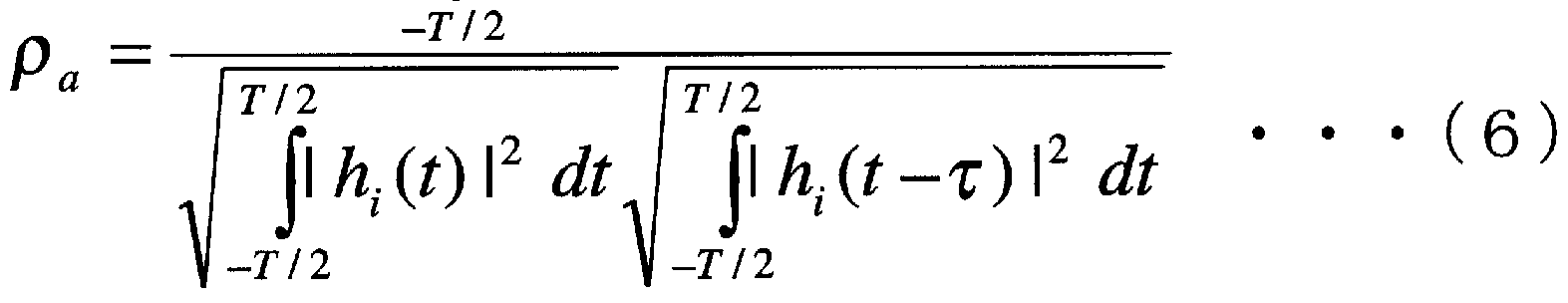
- Equation (1) is expanded into Equation (6).
- Equation (1) is a value of time correlation with respect to propagation path fluctuation.
- Equation 6 The correlation value given by Equation (6) is evaluated by the correlation coefficient p expressed by Equation (8).
- a predetermined value with a small correlation coefficient for example, 0.6 is used as an empirical value.
- Equation (9) shows the result of performing maximum ratio combining of the time correlation for the pilot signal for each transmit antenna with respect to the transmit antenna.
- p (i) is the time correlation for transmit antenna i
- Equation (9) can be calculated.
- weighting is performed by regarding the amplitude value given by the magnitude of I-h (t) I in Equation (2) as the signal reliability.
- Equations (1) and (9) focus only on the time correlation between the same transmit antennas of the received pilot signal. However, since a plurality of different transmission antennas transmit the same symbol data, it is preferable to use a region having a low spatiotemporal correlation in consideration of the spatial region between the transmission antennas.
- FIG. 7 is a conceptual diagram showing a state of diversity gain in time and space domains in a MIMO configuration.
- the transmission symbol data dl from antenna 1 at time tO is the same as the transmission symbol data dl from antenna 2 at time to- ⁇ . Therefore, by calculating the correlation for transmission signals with different transmit antenna power at different times, not only temporal correlation but also spatial correlation will be considered, and calculation with higher accuracy can be expected.
- the spatio-temporal correlation can be calculated from Equation (10).
- the time correlation between the received signals can be calculated for the received pilots from the multiple transmit antennas for the combinations related to the transmit antennas.
- a radio transmission apparatus having a MIMO configuration includes a plurality of antennas on the receiver side as well. Receiving The number of communication antennas is M.
- n (t) be the noise.
- Each transmit antenna power In order to improve the quality of the transmitted pilot signal, maximum ratio combining is used for the receive antenna.
- maximum ratio combining is used for the receive antenna.
- Equations (12) to (14) when there are M receiving antennas.
- Equations (12)-(14) include equations (1), (9), and (10), respectively.
- the timing ⁇ (for example, the correlation coefficient (Equation (8))) at which the value is within a predetermined range close to the time correlation value ⁇ and becomes the shortest time is 0.6.
- the power of setting the transmission diversity switching timing as the timing that is the shortest time below) Implementation of the present invention is not limited to this value.
- Another predetermined value as a time correlation value or correlation coefficient can be used as a guide for switching communication procedures.
- a mode has been described in which a time correlation of an amount corresponding to propagation path variation is calculated using the received pilot signal and reference pilot signal.
- the timing ⁇ should also be determined for the time correlation of the received pilot signal itself or the correlation coefficient force.
- FIG. 8 is a block diagram showing the configuration of the first embodiment of the transmitter of the wireless communication apparatus used in the present communication system.
- This block diagram shows an example with two transmit antennas.
- This transmission unit includes a pilot pattern generation unit 6, an orthogonal code encoding unit 7, and transmission units 12 and 12.
- the transmission units 12 and 12 include a PZS (parallel Z serial) conversion unit 8, a modulation unit 9, a transmission RF unit 10, and a transmission antenna 11.
- the transmission unit includes an STBCor time diversity coding unit 5 that encodes a data stream.
- the present transmission unit has a diversity specification unit 4 for controlling the STBCor time diversity code unit 5, and a bit determination unit 3 for extracting feedback information from the demodulated signal for the control. There is in point.
- Demodulation section 2 includes an antenna that receives feedback information from counterpart wireless communication device 1 and receives feedback information (“means for receiving a command for switching communication procedure from counterpart communication device” of the present invention). Equivalent). Then, the demodulation unit 2 demodulates the received feedback information and sends the force to the bit determination unit 3.
- the bit determination unit 3 performs bit determination of feedback information. That is, the bit determination unit extracts a bit sequence that specifies the code key method as well as the demodulated feedback information power.
- the demodulating unit 2 and the bit determining unit 3 correspond to “means for receiving designation for switching of communication procedures” of the present invention. After that, the bit determination unit 3 notifies the diversity method designating unit 4 of the bit.
- Diversity method designation unit 4 when receiving the bit of feedback information from bit determination unit 3, does not perform processing for a predetermined time set in advance, and after a predetermined time, in accordance with the feedback information, Is set in the STBCor time diversity encoding unit 5.
- Diversity method designation unit 4 and STBCor time diversity code unit 5 correspond to “means for switching to selected communication means” of the present invention.
- the STBCor time diversity encoding unit 5 performs encoding of the data stream 12 by a designated encoding method.
- the pilot pattern generation unit 6 generates a pilot pattern and sends it to the orthogonal code encoding unit 7. To do.
- the orthogonal code encoding unit 7 performs orthogonal code encoding of the pilot pattern, and then transmits the pilot pattern to the PZS conversion unit 8.
- the PZS converter 8 performs the data stream encoded by the STBCor time diversity encoder 5 and the time multiplexing of the orthogonal code-encoded pilot pattern, and then converts the signal into a modulator 9 Send to.
- the data ratio to the pilot signal of PZS conversion is 1: 1, but usually time multiplexing is performed so that the ratio of the data stream becomes high.
- Modulating section 9 digitally modulates the signal and maps it to a signal point.
- the transmission RF unit 10 converts the digital signal into an analog signal, up-converts it to the carrier frequency, and then sends it to the transmission antenna 11.
- FIG. 9 is a block diagram showing a configuration of a second example of the transmission unit of the wireless communication apparatus used in the communication system.
- the configuration of the wireless communication transmitter shown in FIG. 9 is almost the same as the configuration shown in FIG. 8, and therefore the same processing as that described in ⁇ Transmitter 1> is the same as FIG. A reference numeral is attached and description thereof is omitted.
- FIG. 9 shows a form in which the modulation unit 13 performs I and Q separation instead of time multiplexing. For this reason, the PZS conversion unit 8 and the modulation unit 9 in FIG.
- Fig. 9 shows a configuration of a transmission unit in which a pilot signal and a data stream are encoded with orthogonal codes using the I and Q axes. Therefore, the data ratio for the pilot signal is preferably 1: 1. In order to increase the ratio of data, it can be improved by increasing the number of data mapping points on the I and Q axes. However, this operation is not preferable because it changes the amplitude ratio of the I and Q axes.
- pilot signals can be transmitted and received by occupying one orthogonal axis by orthogonal code codes using the I and Q axes. Therefore, the correlation can be calculated with higher quality communication than when PZS conversion is used.
- FIG. 10 is a block diagram showing the configuration of the first embodiment of the receiving unit of the wireless communication device of the present wireless communication system.
- FIG. 10 shows a receiving unit used for the configuration of the transmitting unit in FIG.
- the receiving unit includes a demodulating unit 19 and transmitting units 28 and 28 which are two when there are two receiving antennas.
- the transmission units 28 and 28 include a reception antenna 14, a reception RF unit 15, a timing synchronization unit 16, and an SZP (serial Z parallel) conversion unit 17.
- this receiving unit is diversity decoding unit 21, orthogonal code decoding unit 18, propagation path estimation unit 20, time correlation detection unit 22, diversity switching notification unit 24, and transmission diversity selection unit 25. And a feedback bit generation unit 26.
- the receiving antenna 14 receives a signal from the counterpart communication device (corresponding to “reception means for receiving a radio signal from the counterpart communication device” of the present invention).
- the reception RF unit 15 down-converts the received signal, converts it to a digital signal, and sends it to the force timing synchronization unit 16.
- the timing synchronization unit 16 synchronizes timing for performing signal processing after performing path detection, AFC synchronization, and the like. Thereafter, the timing synchronization unit 16 sends the signal to the SZP conversion unit 17.
- the SZP conversion unit 17 performs SZP (serial Z parallel) conversion corresponding to the transmission format, and separates the received noro signal from the data stream.
- the orthogonal code decoding unit 18 extracts the cut pilot signal as a reception pilot signal for each transmission antenna.
- the propagation path estimation unit 20 estimates the variation of the received signal due to the propagation path using the received pilot signal and the reference pilot signal. Thereafter, the signal is sent to the demodulator 19 and the time correlation detector 22.
- the demodulator 19 corrects the fluctuation of the radio propagation path by determining the maximum likelihood of the signal with the estimated value (channel estimation value) of the propagation path fluctuation between the respective transmitting and receiving antennas. Thereafter, the signal is sent to diversity decoder 21.
- Diversity decoding section 21 decodes the signal according to the selected transmission diversity scheme to generate data stream 23.
- STBC selected when decoding signal If time diversity is selected, information on delay due to propagation path and delay due to control is obtained from the system design time, so maximum ratio combining is used.
- MPIC Multi-Path Interference Canceller
- the diversity decoding unit 21 switches to the transmission diversity demodulation method notified of the transmission diversity demodulation method.
- the time correlation detection unit 22 has a memory for storing a buffer and an arithmetic processing unit for data registered in the memory.
- the time correlation detection unit 22 registers the received pilot signal after orthogonal code decoding in a memory in a time series for a predetermined period (corresponding to “means for storing a received signal received for a predetermined period” of the present invention). Thereafter, the time correlation detection unit 22 reads the data registered in the memory and calculates the time correlation in a predetermined time range.
- the time correlation detection unit 22 calculates the shortest time difference at which the time correlation value is 0 or the correlation coefficient is 0.6 or less as the timing ⁇ (the “first reference time point of the present invention” Corresponds to “means for obtaining the time difference from the second reference time point where the time correlation is within a predetermined range”. Then, the transmission diversity selection unit 25 is notified of this value.
- the time correlation detection unit 22 receives a notification that no processing is performed for a predetermined time from the diversity notification unit 24, and registers the received pilot signal in the memory by the built-in timer.
- a function of not performing the time correlation calculation process may also be provided (corresponding to the “means for suspending the time correlation calculation” of the present invention).
- a function for starting detection of time correlation after a time determined by a built-in timer may be provided (corresponding to “means for starting calculation of time correlation” of the present invention).
- the transmission diversity selector 25 selects transmission diversity based on the timing information ⁇ .
- the transmission diversity selection unit 25 notifies the selected transmission diversity method to the feed knock bit generation unit 26 and the diversity switching notification unit 24.
- the transmission diversity selection unit 25 includes a memory for registering a transmission diversity method that is currently used, and each time the selected transmission diversity method is applied to the system. The timing information notified from the time correlation detection unit 22 is updated. If the transmission diversity method selected based on the information is the same as the transmission diversity method read from the corresponding memory, a feedback bit switching unit 26 and a diversity switching notification unit 24 are notified of the transmission diversity method switching. You may provide a function that does not notify This also means that the other communication device is not notified of the selected transmission diversity type.
- the diversity switching notification unit 24 switches the communication procedure in synchronization with the partner communication device.
- the details of diversity switching timing are explained in ⁇ Diversity Switching Timing>.
- the feedback bit generator 26 generates a bit sequence corresponding to the selected transmission diversity scheme. Then, the bit sequence is sent to the modulation unit 27 as feedback information.
- Modulator 27 modulates the feedback information and transmits the feedback information to the counterpart wireless communication device through the radio propagation path (“command for commanding selected radio communication means to counterpart communication device of the present invention”). Equivalent to "means").
- the configuration of the receiving unit with respect to the configuration of the transmitting unit in FIG. 9 is based on orthogonal demodulation using I and Q axes instead of the SZP (serial Z parallel) converting unit 17 and the demodulating unit 19 in FIG. It can be obtained by visiting the club.
- SZP serial Z parallel
- transmission diversity is notified between the transmitter and the receiver, so the number of feedback bits is increased by the amount related to the notification of transmission diversity compared to the conventional technology.
- a function for reducing the amount of communication between the transceivers will be described.
- FIG. 21 shows the power to use transmission diversity and ARQ to be used for the diversity mode and the MIMO multiple mode.
- ON means use of the communication procedure
- OFF means nonuse.
- This communication system supports the diversity mode, and the communication procedure is set as shown in FIG.
- ARQ Automatic Repeat reQuest
- the feedback information used for ACK / NACK information can be reduced.
- the conventional technology MIMO In the case of the multiplex mode, feedback information regarding transmission diversity is not necessary. Feedback information as a power ARQ is necessary.
- the transmission diversity selection unit 25 selects a communication procedure to be used between the transceivers according to the magnitude of the timing ⁇ notified from the time correlation detection unit 22.
- a communication procedure one of the communication procedures shown in FIG. 20 as an example is selected according to the timing.
- FIG. 22 shows the relationship between the magnitude of the timing ⁇ at which the time correlation of the received pilot signal becomes small and the communication procedure to be applied. If ⁇ is smaller than the time for retransmission control (ARQ) (ARQ period), time diversity is appropriate.
- STBC is suitable when there are two transmitting antennas and the time is sufficiently short for a symbol time of 2 km, which is proportional to the number of antennas.
- STBC using quasi-orthogonal coding is suitable when the number of transmitting antennas is 3 or more and ⁇ is sufficiently small for the symbol time NT proportional to the number of antennas. If N is equal to or more than 3 transmit antennas and ⁇ is sufficiently small compared to 2NT, which is proportional to twice the number of antennas, STBC using Orthogonal Coding is suitable.
- the characteristics of time diversity when compared to STBC with two transmit antennas are that diversity can be obtained even if the spatial correlation becomes 1, and transmission is performed multiple times in all time widths. By doing so, diversity can be improved.
- the characteristics of STBC using Orthogonal Coding when there are three transmit antennas are that diversity increases in proportion to the transmit antenna, and that orthogonalization is complicated, which requires a large number of symbols, which reduces throughput. It is to be.
- the characteristics of STBC using quas Orthogonal Coding when there are three transmit antennas are that it maintains almost orthogonality in terms of orthogonalization and that diversity is improved in proportion to the transmit antenna.
- the relationship of the characteristics of transmit diversity to the magnitude of timing ⁇ is known. Therefore, a table of the relationship between the range of ⁇ values and the type of transmission diversity to be selected within that range may be created.
- the specific relationship between the value of ⁇ and transmission diversity depends on the amount of computation processing that depends on the system, as well as the characteristics of transmission diversity described above. It is determined. For example, if the system can withstand a large amount of feedback information, the number of types of feedback bits can be increased and finer control can be performed. Also, if time diversity processing can be performed at high speed, three-time transmission time diversity is preferred over double-transmission time diversity.
- the device force can also be obtained in advance.
- the delay refers to the transmission propagation path delay in which the pilot signal and data are multiplexed and transmitted to the reception side on the transmission side, and the pilot signal power on the reception side is also used to calculate propagation path estimation and time correlation to select transmission diversity.
- Receiver control delay until the feedback bit is sent reception propagation path delay until the feedback bit is sent to the transmitter, transmitter control delay until the transmission bit on the transmitter side is switched after judging the feedback bit I ’m going to go. The sum of all these is the total delay.
- the maximum propagation path delay a is determined based on the maximum cell radius.
- the control delay b is determined based on the total time of the time required for switching the communication means of the transmitting-side wireless communication device and the time required for switching the communication means of the receiving-side wireless communication device.
- Fig. 16 is a conceptual diagram showing a state in which signals are transmitted with respect to the time axis.
- the time direction refers to the direction going back along the time axis.
- Figure 16 shows the signal configuration with pilot signals in the second half of the slot. The figure assumes that the total delay of maximum propagation path delay a and control delay b is shorter than one slot.
- an appropriate transmission diversity can be selected based on the time correlation using up to the pilot signal of slot 1.
- the selected transmit diversity can be applied to slot 3 even if the total delay is taken into account. In this case, when the receiving side receives the slot 1 slot signal, the transmitting side is ready to transmit to slot 2.
- the feedback bit specifying the selected transmit diversity is returned to the transmitting side, and even if the determination is made, the slot 3 time is not reached. Therefore, if the decision result is applied from the next slot, the change in transmit diversity is reflected in slot 3. Even on the receiving side, the data decoding process of slot 2 is shifted during the control delay of the time correlation calculation, so switching control can be performed in slot 3 by waiting for the next slot and applying it.
- FIG. 17 shows a configuration in which a pilot signal is present in the first half of the slot.
- the maximum total delay maximum propagation path delay a + control delay b
- the result of time correlation using the pilot signal up to slot 1 Transmit diversity determined using can be applied to slot 2.
- the maximum total delay time (a + b) is 1 slot or more and less than 2 slots. Therefore, depending on the propagation environment, it is uncertain whether the total delay time is 1 slot or 2 slots. If this is uncertain, we consider the timing for switching transmit diversity using a frame that combines multiple combinations of data and pilot signals (slots) and! /.
- FIG. 18 shows an example in which one frame is composed of three slots.
- transmit diversity is selected based on the time correlation using the nolot signal up to the first slot of the frame.
- the selected transmission diversity is applied from the first slot of the next frame.
- the determination result using the no-lot signal up to slot 1 can be reflected in slot 4 which is the head of the next frame.
- transmission diversity switching can be performed by determining slots and frames according to the maximum delay time set as a brute force system. Timing control can be realized.
- the timing obtained from the control delay of the transmitter and the propagation delay according to the cell radius is incorporated in advance when designing the system and is sufficiently large to accommodate various radio base stations and radio equipment. Designed with a frame of
- the diversity switching notifying unit 24 and the diversity decoding unit 21 that switch the transmission diversity method in synchronization with the transmitting-side wireless communication device are used in the “selected wireless communication” in the receiving-side wireless communication device of the present invention.
- the diversity control designating unit 4 and the STBCor time diversity code unit 5 for switching the transmission diversity method in synchronization with the receiving-side wireless communication device according to the above control are used in the transmitting-side wireless communication device of the present invention. This corresponds to “switching control means for switching the selected wireless communication procedure”.
- the demodulation unit 2, the bit determination unit 3, the diversity scheme designation unit 4, and the STBCor time diversity encoding unit 5 shown in FIG. 8 are on a CPU (Central Processing Unit) or DSP (Digital Signal Processor). It can be realized as a program. However, some of these components may be configured by a dedicated arithmetic circuit.
- CPU Central Processing Unit
- DSP Digital Signal Processor
- FIG. 23 is a flowchart of diversity switching processing in the transmission unit.
- the feedback information that has received the power of the counterpart wireless device is demodulated by the demodulator 2 and then the bit information Sent to fixed part 3.
- the bit determination unit 3 determines a feedback bit based on the received signal (S13).
- the diversity scheme designating unit 4 selects transmission diversity based on the determined bits (S14). Further, the diversity method designating unit 4 synchronizes the timing related to the feedback control delay, including the transmission diversity switching timing in the transceiver (S15). For example, diversity scheme designating section 4 switches transmission diversity at the third slot counting from the slot including the first pilot when there is a relationship between the total delay and the slot as shown in FIG. Also, as shown in FIG.
- diversity scheme designating section 4 sets a sufficiently long frame for the control time on the transmitting side and the receiving side. In this way, the transmission diversity scheme designating unit 4 notifies the STBCor time diversity code receiving unit 5 of a transmission diversity code switching command (S16). Then, the STBCor time diversity coding unit 5 receives the notification regarding the switching of the transmission diversity and switches the communication procedure to the notified transmission diversity method. Based on the switched transmission diversity method, the STBCor time diversity coding unit 5 encodes the data stream.
- the transmission unit can switch the transmission diversity coding scheme in synchronization with the reception unit.
- system principle equation (1) is applied in the case of a communication device of MISO configuration
- system principle equation (12) is applied in the case of a communication device of MIMO configuration. It corresponds.
- the propagation path estimation unit 20, the diversity decoding unit 21, the time correlation detection unit 22, the diversity switching notification unit 24, the transmission diversity selection unit 25, the feedback bit generation unit 26, and the modulation unit 27 in FIG. It can be realized as a program on CPU (Central Processing Unit) or DSP (Digital Signal Processor). However, some of these components may be configured by a dedicated arithmetic circuit.
- CPU Central Processing Unit
- DSP Digital Signal Processor
- FIG. 11 is a flowchart of diversity switching processing in the receiving unit.
- the receiving communication device power receiving antenna 14 receives the pilot signal of the other communication device power and sends it to the receiving RF unit 15.
- the reception RF unit 15 receives the reception signal from the reception antenna 14 and converts it into a digital signal, and then sends the signal to the timing synchronization unit 16.
- the timing synchronization unit 16 performs timing synchronization for signal processing, and then sends the signal to the SZP conversion unit 17.
- the SZP conversion unit performs serial Z parallel conversion of the signal, and then sends the signal to the orthogonal code decoding unit 18 and the decoding unit 19.
- the received signal sent to the orthogonal code decoding unit 18 is decoded with respect to the orthogonal code, and then sent to the propagation path estimation unit 20.
- the propagation path estimation unit 20 estimates the propagation path fluctuation of the received signal (Sl).
- the time correlation detection unit 22 calculates a time correlation using a received signal having a transmission antenna power arbitrarily selected in advance and a reference pilot signal for the received signal.
- the time correlation detection unit 22 calculates the time correlation of the received signal with respect to a set of a transmission antenna arbitrarily selected in advance and each receiving antenna.
- the time correlation detection unit 22 that executes this step corresponds to “means for calculating a time correlation with one received signal” of the present invention (S2).
- the time correlation detection unit 22 maintains the time correlation value obtained in step S2 as it is.
- the time correlation detection unit 22 calculates the average value of the propagation path fluctuation in a predetermined time width with respect to the receiving antenna, and then determines the magnitude of the propagation path fluctuation as the reliability of the received signal. Considering this, the maximum ratio of time correlation is combined to improve the accuracy of the time correlation value (S3).
- the time correlation detection unit 22 determines a time difference and timing ⁇ at which the time correlation becomes smaller from the calculated time correlation value (S4).
- the transmission diversity selection unit 25 selects transmission diversity from the timing ⁇ (S5).
- the transmission diversity selection unit 25 notifies the selected transmission diversity information to the feedback bit generation unit 26 and the diversity switching notification unit 24 (S6).
- the feedback bit generator 26 converts the transmission diversity information into a bit format to be transmitted as a signal (S7).
- Figure 20 shows an example of the bit format of S7.
- the signal converted in step S7 is fed back to the transmitting side radio communication apparatus as feedback information by the modulator 27.
- the diversity switching notifying unit 24 measures timing synchronization in order to switch the transmission diversity method in synchronization with the signal transmitted from the transmitting side wireless communication device (S8).
- the diversity switching notification unit 24 Based on the timing synchronization of step S8, the transmission diversity method is switched in synchronism with the transmitting wireless communication device (S9).
- Diversity decoding unit 21 decodes the received signal using the switched transmission diversity method, and extracts the data stream.
- the time from the reception pilot signal from one of the transmission antennas is determined. After the correlation is calculated and determined, the transmission diversity is selected and the transmitter is notified as feedback information.On the other hand, after the timing with the transmitter is achieved, the diversity method of the receiver is changed. Can be switched.
- the steps S2 and S3 in the first embodiment are different steps.
- the second embodiment corresponds to the embodiment of the system principle equation (9) in the case of the MISO configuration communication device, and the system principle equation (13) in the case of the MIMO configuration communication device.
- the second embodiment will be described below using the flowchart of the processing of the receiving unit shown in FIG. However, regarding the same processing as that described in the first embodiment, the same reference numerals as those in FIG.
- the second embodiment is different from the first embodiment in that the steps S2 and S3 of the first embodiment are S2A and S3A.
- the processing steps of S2A and S3A are as follows.
- the time correlation detection unit 22 calculates the time correlation of received signals from a plurality of transmission antennas.
- the time correlation detection unit 22 calculates the time correlation of received signals having a plurality of transmitting antenna powers for a pair with a plurality of receiving antennas.
- the time correlation detection unit 22 that executes this step corresponds to “means for calculating a plurality of the received radio signal forces also for the plurality of time correlations” of the present invention (S2A).
- the time correlation detection unit 22 calculates the average value of propagation path fluctuations for a plurality of transmission antennas, and then uses the value to synthesize the maximum ratio of time correlation values.
- the time correlation detection unit 22 calculates an average value of propagation path fluctuations for a set of a plurality of transmission antennas and a plurality of reception antennas, The maximum ratio composition of the time correlation values is performed using the values.
- the time correlation detection unit 22 that executes this step is a synthesized time correlation weighted by the magnitude of each power value of the plurality of received signals from the plurality of time correlations and the plurality of received signals. (S3A).
- the third embodiment will be described using the flowchart of the processing of the reception unit shown in FIG.
- the same reference numerals as those in FIG. The second embodiment is different from the first embodiment in that the steps S2 and S3 of the first embodiment are S2B and S3B.
- the time correlation detection unit 22 calculates the time correlation of received signals having a plurality of transmitting antenna powers. When calculating the time correlation, the time correlation is calculated for multiple sets of transmit antennas. In the case of the MIMO configuration, the time correlation detection unit 22 calculates the time correlation of the received signals having a plurality of transmitting antenna forces for each of the plurality of receiving antennas. That is, the time correlation detection unit 22 calculates the time correlation for each set of receiving antennas when calculating the time correlation.
- the time correlation detection unit 22 may calculate the time correlation only for a pair of adjacent transmission antennas with respect to a plurality of transmission antennas.
- the time correlation detection unit 22 that executes this step corresponds to “means for calculating a time correlation for a combination of a plurality of received signals” of the present invention (S2B).
- the time correlation detection unit 22 maintains the time correlation value obtained in step S2 as it is.
- the time correlation detection unit 22 calculates the average value of propagation path fluctuations for a plurality of reception antennas, and then uses the value to calculate the time correlation value obtained for each of the plurality of reception antennas.
- Maximum ratio synthesis S3B).
- the time correlation can be calculated taking into account the spatial separation of a plurality of transmission antennas.
- a step (S10) of waiting until the next calculation timing is added to the second embodiment.
- Other processing in this embodiment is the same as that described in the second embodiment (FIG. 12). Therefore, the same processes as those described in the second embodiment are denoted by the same reference numerals and description thereof is omitted.
- the diversity switching notifying unit 24 notifies the time correlation detecting unit 22 that the calculation of the time correlation calculation is suspended for a while (S10). Then, according to the notification from the diversity switching notification unit 24, the time correlation detection unit 22 measures time for a preset period with the built-in timer, and does not calculate the time correlation during that time (executes this processing).
- the time correlation detection unit 22 corresponds to “means for measuring a predetermined pause time” in the present invention).
- the amount of computation for calculating the time correlation between received signals is large, the amount of computation used in this system can be calculated by intermittently executing computation processing after waiting for an interval. Can be reduced.
- the step S10 may be added to each step of the first example.
- the step S10 can be added to each step of the embodiment.
- a step (S11) for determining whether or not to switch transmission diversity and a step (S12) for not performing switching control are added to the fourth embodiment.
- Other processes in this example are the same as those described in the second example (FIG. 12). Therefore The same processes as those described in the second embodiment are designated by the same reference numerals and the description thereof is omitted.
- the transmission diversity selection unit 25 determines from the ⁇ notified from the time correlation detection unit 22 whether the corresponding transmission diversity is the same as the transmission diversity method currently in use. judge.
- the transmission diversity selection unit 25 that executes this step corresponds to “means for determining whether the selected communication procedure and the communication procedure used before the selection are the same” or not (Sl l).
- the transmission diversity selection unit 25 determines that the selected transmission diversity and the transmission diversity currently in use are the same, the transmission diversity selection unit 25 does not notify the feedback generation unit 26 regarding switching of transmission diversity V, .
- the transmission diversity selection unit 25 that executes this step corresponds to “means for not instructing the other communication device of the selected communication procedure” of the present invention.
- the transmission diversity selection unit 25 does not notify the diversity switching notification unit 24 of the transmission diversity switching.
- the transmission diversity selection unit 25 that executes this step corresponds to “means not to switch communication procedure” of the present invention (S12).
- the transmission diversity selection unit 25 selects the same method as the transmission diversity currently in use, the transmission diversity is switched between the transmission side wireless communication device and the reception side wireless communication device. The amount of calculation for timing synchronization can be reduced.
- the steps S2 and S3 of the first embodiment or the steps S2B and S3B of the third embodiment can be used instead of the steps S2A and S3A.
- the transmission side is a radio base station and the reception side is a radio terminal
- the transmission side may be a radio terminal and the reception side may be a radio base station.
- the transceiver may be a wireless terminal or a wireless base station.
- the time correlation for the fading fluctuation was obtained. Also applicable. Fluctuations observed in a short time of the received pilot signal can be regarded as fluctuations that occur during fading. On the other hand, fluctuations caused by shadowing can be regarded as fluctuations observed in a relatively long time of the received pilot signal. Therefore, when calculating the time correlation, the received pilot signal after the averaging operation is performed after the average operation of the received pilot signal is performed for a predetermined time width where the effect of fading disappears. By using this to calculate the temporal correlation, the influence of shadowing can be calculated as the value of the temporal correlation. Other processes are the same as those in the embodiment for fading. Therefore, it is possible to switch radio procedures that are also effective for shadowing.
- a configuration that reliably transmits and receives feedback information will be described.
- the configuration of the transmission unit will be described.
- Fig. 24 shows the relationship between the feedback bit transmission control reliability improvement method and its characteristics.
- selectable reliability improvement techniques include error correction coding, multiple identical symbol transmissions, bit likelihood determination, and transmission power increase.
- the characteristics of each of these technologies are that, in the case of an error correction code, a certain amount of computation is required for decoding the error correction, the gain due to the sign ⁇ is very large, and the feedback amount is redundant. It is mentioned that. For multiple transmissions of the same symbol and bit likelihood determination, the amount of calculation of the determination method is small, the gain by likelihood determination is large, and the feedback information becomes more redundant when trying to obtain the same gain as the error correction code Can be mentioned.
- the reliability improvement methods listed in Fig. 24 have their own characteristics as shown in the figure. By using these reliability improvement methods and these control methods in combination, reliable feedback can be obtained. Can send and receive become.
- FIG. 25 a feedback bit control decoding unit 29 is added to the components of FIG.
- the feedback bit control decoding unit 29 decodes the feedback bit encoded on the receiver side, such as error correction coding, transmission of a plurality of symbol data, and bit likelihood determination. Or, when the transmission power is increased on the receiver side, the interface for receiving control commands from the higher layer 30 that manages radio resources for power control etc. is feedback bit control decoding Part 29 is provided.
- Other processes in this modification are the same as those described in ⁇ Transmitter 1> (FIG. 8). Therefore, the same processes as those described in ⁇ Transmitter 1> are denoted by the same reference numerals and description thereof is omitted.
- control delay that occurs when each reception method is used is also taken into account when designing the system and reflected in the switching timing of the transceiver.
- a configuration for performing transmission / reception of feedback information more reliably than the embodiment shown in FIG. 10 will be described.
- the configuration of the receiving unit will be described.
- FIG. 26 The difference between FIG. 26 and FIG. 10 is that in FIG. 26, a feedback bit control decoding unit 31 is added in addition to the components of FIG.
- the feedback bit control encoding unit 31 encodes feedback bits decoded on the transmitter side, such as error correction encoding, transmission of a plurality of symbol data, and bit likelihood determination.
- an interface for receiving a control command from the upper layer 32 that manages radio resources for power control and the like is provided in the feedback control encoding unit 31.
- Other processing in this modification is described in ⁇ Receiving unit> (Fig. 10). It is the same as the case of. Therefore, the same processes as those described in ⁇ Receiving unit> are denoted by the same reference numerals, and description thereof is omitted.
- control delay that occurs when each technology is used is also taken into account when designing the system, and is reflected in the switching timing of the transceiver.
Abstract
Description


Claims
Priority Applications (4)
| Application Number | Priority Date | Filing Date | Title |
|---|---|---|---|
| JP2007507978A JP4824016B2 (ja) | 2005-03-15 | 2005-03-15 | 通信装置および通信方法 |
| EP05720825.8A EP1860789A4 (en) | 2005-03-15 | 2005-03-15 | COMMUNICATION DEVICE AND COMMUNICATION PROCESS |
| PCT/JP2005/004570 WO2006098008A1 (ja) | 2005-03-15 | 2005-03-15 | 通信装置および通信方法 |
| US11/898,712 US7684527B2 (en) | 2005-03-15 | 2007-09-14 | Communication device and communication method |
Applications Claiming Priority (1)
| Application Number | Priority Date | Filing Date | Title |
|---|---|---|---|
| PCT/JP2005/004570 WO2006098008A1 (ja) | 2005-03-15 | 2005-03-15 | 通信装置および通信方法 |
Related Child Applications (1)
| Application Number | Title | Priority Date | Filing Date |
|---|---|---|---|
| US11/898,712 Continuation US7684527B2 (en) | 2005-03-15 | 2007-09-14 | Communication device and communication method |
Publications (1)
| Publication Number | Publication Date |
|---|---|
| WO2006098008A1 true WO2006098008A1 (ja) | 2006-09-21 |
Family
ID=36991368
Family Applications (1)
| Application Number | Title | Priority Date | Filing Date |
|---|---|---|---|
| PCT/JP2005/004570 WO2006098008A1 (ja) | 2005-03-15 | 2005-03-15 | 通信装置および通信方法 |
Country Status (4)
| Country | Link |
|---|---|
| US (1) | US7684527B2 (ja) |
| EP (1) | EP1860789A4 (ja) |
| JP (1) | JP4824016B2 (ja) |
| WO (1) | WO2006098008A1 (ja) |
Cited By (3)
| Publication number | Priority date | Publication date | Assignee | Title |
|---|---|---|---|---|
| WO2009008275A1 (en) * | 2007-07-09 | 2009-01-15 | Canon Kabushiki Kaisha | Communication apparatus, communication method, and computer program for making computer execute communication method |
| WO2010103989A1 (ja) * | 2009-03-10 | 2010-09-16 | シャープ株式会社 | 無線通信システム、無線送信装置および無線送信装置の制御プログラム |
| JPWO2014006961A1 (ja) * | 2012-07-06 | 2016-06-02 | 日本電気株式会社 | フェージングドップラ周波数推定装置およびフェージングドップラ周波数推定方法 |
Families Citing this family (31)
| Publication number | Priority date | Publication date | Assignee | Title |
|---|---|---|---|---|
| US9192859B2 (en) | 2002-12-10 | 2015-11-24 | Sony Computer Entertainment America Llc | System and method for compressing video based on latency measurements and other feedback |
| US20090118019A1 (en) * | 2002-12-10 | 2009-05-07 | Onlive, Inc. | System for streaming databases serving real-time applications used through streaming interactive video |
| US8366552B2 (en) * | 2002-12-10 | 2013-02-05 | Ol2, Inc. | System and method for multi-stream video compression |
| US8964830B2 (en) | 2002-12-10 | 2015-02-24 | Ol2, Inc. | System and method for multi-stream video compression using multiple encoding formats |
| US10201760B2 (en) * | 2002-12-10 | 2019-02-12 | Sony Interactive Entertainment America Llc | System and method for compressing video based on detected intraframe motion |
| US9108107B2 (en) * | 2002-12-10 | 2015-08-18 | Sony Computer Entertainment America Llc | Hosting and broadcasting virtual events using streaming interactive video |
| US9061207B2 (en) | 2002-12-10 | 2015-06-23 | Sony Computer Entertainment America Llc | Temporary decoder apparatus and method |
| US9138644B2 (en) * | 2002-12-10 | 2015-09-22 | Sony Computer Entertainment America Llc | System and method for accelerated machine switching |
| US9446305B2 (en) | 2002-12-10 | 2016-09-20 | Sony Interactive Entertainment America Llc | System and method for improving the graphics performance of hosted applications |
| US8549574B2 (en) | 2002-12-10 | 2013-10-01 | Ol2, Inc. | Method of combining linear content and interactive content compressed together as streaming interactive video |
| US8949922B2 (en) * | 2002-12-10 | 2015-02-03 | Ol2, Inc. | System for collaborative conferencing using streaming interactive video |
| US9077991B2 (en) * | 2002-12-10 | 2015-07-07 | Sony Computer Entertainment America Llc | System and method for utilizing forward error correction with video compression |
| US9314691B2 (en) * | 2002-12-10 | 2016-04-19 | Sony Computer Entertainment America Llc | System and method for compressing video frames or portions thereof based on feedback information from a client device |
| US8526490B2 (en) * | 2002-12-10 | 2013-09-03 | Ol2, Inc. | System and method for video compression using feedback including data related to the successful receipt of video content |
| US8711923B2 (en) | 2002-12-10 | 2014-04-29 | Ol2, Inc. | System and method for selecting a video encoding format based on feedback data |
| US7706328B2 (en) | 2006-01-04 | 2010-04-27 | Qualcomm Incorporated | Methods and apparatus for position location in a wireless network |
| US8194544B2 (en) * | 2006-11-22 | 2012-06-05 | Belair Networks Inc. | Network delay shaping system and method for backhaul of wireless networks |
| US7822102B2 (en) * | 2007-01-09 | 2010-10-26 | Broadcom Corporation | Method and system for an efficient channel quantization method for MIMO pre-coding systems |
| US20090028100A1 (en) * | 2007-07-25 | 2009-01-29 | Qualcomm Incorporated | Methods and apparatus for transmitter identification in a wireless network |
| GB0720559D0 (en) | 2007-10-19 | 2007-11-28 | Fujitsu Ltd | MIMO wireless communication system |
| US9168457B2 (en) | 2010-09-14 | 2015-10-27 | Sony Computer Entertainment America Llc | System and method for retaining system state |
| CN101459635B (zh) * | 2007-12-14 | 2011-03-16 | 华为技术有限公司 | 空分多址接入系统提高吞吐量性能的方法、系统及装置 |
| US8218519B1 (en) * | 2008-01-23 | 2012-07-10 | Rockwell Collins, Inc. | Transmit ID within an ad hoc wireless communications network |
| US8165064B2 (en) * | 2008-01-28 | 2012-04-24 | Qualcomm Incorporated | Enhancements to the positioning pilot channel |
| US8170477B2 (en) * | 2008-04-04 | 2012-05-01 | Broadcom Corporation | Robust wireless communication device |
| US20090274099A1 (en) * | 2008-05-02 | 2009-11-05 | Qualcomm Incorporated | Methods and apparatus for communicating transmitter information in a communication network |
| WO2010095887A2 (ko) * | 2009-02-20 | 2010-08-26 | (주)엘지전자 | 릴레이 방식의 통신 시스템에서 백홀 링크의 기준신호 할당 방법 및 이를 통한 데이터 송수신 방법 및 장치 |
| GB0917452D0 (en) * | 2009-10-06 | 2009-11-18 | Cambridge Silicon Radio Ltd | Radio transmitter apparatus |
| TWI470958B (zh) * | 2012-01-03 | 2015-01-21 | Mstar Semiconductor Inc | 應用於無線網路接收端以判斷發射端天線數目的方法與相關裝置 |
| US9276653B2 (en) * | 2012-04-10 | 2016-03-01 | Lattice Semiconductor Corporation | Antenna selection and pilot compression in MIMO systems |
| BR112015002353A2 (pt) * | 2012-08-02 | 2017-11-07 | Huawei Tech Co Ltd | dispositivo, sistema e método de retransmissão de dados |
Citations (6)
| Publication number | Priority date | Publication date | Assignee | Title |
|---|---|---|---|---|
| JPH03135233A (ja) * | 1989-10-20 | 1991-06-10 | Nippon Telegr & Teleph Corp <Ntt> | 移動通信用一周波数交互通信方式 |
| JP2000252893A (ja) * | 1999-03-03 | 2000-09-14 | Nec Corp | 無線通信システム及びそれに用いる基地局並びに移動機 |
| JP2001358621A (ja) * | 2000-06-15 | 2001-12-26 | Fujitsu Ltd | フェージング周波数推定回路及び該回路を備えたcdma受信装置 |
| JP2002016534A (ja) * | 2000-06-29 | 2002-01-18 | Matsushita Electric Ind Co Ltd | 無線基地局装置及び無線通信方法 |
| JP2003332954A (ja) * | 2002-05-16 | 2003-11-21 | Ntt Docomo Inc | 無線基地局及び無線通信制御方法 |
| JP2003347980A (ja) * | 2002-05-29 | 2003-12-05 | Ntt Docomo Inc | 移動局、無線基地局、無線通信制御方法、及びフェージング周波数推定方法 |
Family Cites Families (41)
| Publication number | Priority date | Publication date | Assignee | Title |
|---|---|---|---|---|
| JP3156768B2 (ja) * | 1998-01-21 | 2001-04-16 | 日本電気株式会社 | セルラ基地局およびそれに搭載される位置標定装置 |
| FI108588B (fi) * | 1998-12-15 | 2002-02-15 | Nokia Corp | Menetelmä ja radiojärjestelmä digitaalisen signaalin siirtoon |
| JP4161455B2 (ja) | 1999-03-19 | 2008-10-08 | 三菱電機株式会社 | 移動体通信システム |
| US6865237B1 (en) * | 2000-02-22 | 2005-03-08 | Nokia Mobile Phones Limited | Method and system for digital signal transmission |
| US20010033622A1 (en) * | 2000-03-14 | 2001-10-25 | Joengren George | Robust utilization of feedback information in space-time coding |
| WO2001069814A1 (en) * | 2000-03-15 | 2001-09-20 | Nokia Corporation | Transmit diversity method and system |
| FI20000851A (fi) * | 2000-04-10 | 2001-10-11 | Nokia Networks Oy | Tiedonsiirtomenetelmä ja radiojärjestelmä |
| US6834043B1 (en) * | 2000-07-24 | 2004-12-21 | Motorola, Inc. | Method and device for exploiting transmit diversity in time varying wireless communication systems |
| US6778612B1 (en) * | 2000-08-18 | 2004-08-17 | Lucent Technologies Inc. | Space-time processing for wireless systems with multiple transmit and receive antennas |
| US7248638B1 (en) * | 2001-03-23 | 2007-07-24 | Lsi Logic | Transmit antenna multi-mode tracking |
| JP3553517B2 (ja) * | 2001-03-23 | 2004-08-11 | 松下電器産業株式会社 | 周波数オフセット量推定装置 |
| US6859503B2 (en) * | 2001-04-07 | 2005-02-22 | Motorola, Inc. | Method and system in a transceiver for controlling a multiple-input, multiple-output communications channel |
| US7133459B2 (en) * | 2001-05-01 | 2006-11-07 | Texas Instruments Incorporated | Space-time transmit diversity |
| US7031419B2 (en) * | 2001-06-29 | 2006-04-18 | Nokia Corporation | Data transmission method and system |
| US7164649B2 (en) * | 2001-11-02 | 2007-01-16 | Qualcomm, Incorporated | Adaptive rate control for OFDM communication system |
| EP1359684A1 (en) * | 2002-04-30 | 2003-11-05 | Motorola Energy Systems Inc. | Wireless transmission using an adaptive transmit antenna array |
| US7184713B2 (en) * | 2002-06-20 | 2007-02-27 | Qualcomm, Incorporated | Rate control for multi-channel communication systems |
| KR100899735B1 (ko) * | 2002-07-03 | 2009-05-27 | 삼성전자주식회사 | 이동 통신 시스템에서 적응적 전송 안테나 다이버시티장치 및 방법 |
| ATE375634T1 (de) * | 2002-08-05 | 2007-10-15 | Nokia Corp | Sende-diversität mit zwei kreuzpolarisationsgruppenantennen |
| JP3679075B2 (ja) | 2002-09-13 | 2005-08-03 | 松下電器産業株式会社 | 無線送信装置および無線送信方法 |
| US8218609B2 (en) * | 2002-10-25 | 2012-07-10 | Qualcomm Incorporated | Closed-loop rate control for a multi-channel communication system |
| EP1445886B1 (en) * | 2003-01-31 | 2015-05-20 | Ntt Docomo, Inc. | Multiple-output multiple-input (MIMO) communication system, MIMO receiver and MIMO receiving method |
| EP1596516A4 (en) * | 2003-02-17 | 2014-12-10 | Panasonic Mobile Comm Co Ltd | NOISE ESTIMATION METHOD AND NOISE ESTIMATION ESTABLISHMENT |
| JP3815483B2 (ja) * | 2003-03-12 | 2006-08-30 | 日本電気株式会社 | 無線端末装置 |
| US7197082B2 (en) * | 2003-03-20 | 2007-03-27 | Lucent Technologies Inc. | Linear transformation of symbols to at least partially compensate for correlation between antennas in space time block coded systems |
| KR100591890B1 (ko) * | 2003-04-01 | 2006-06-20 | 한국전자통신연구원 | 다중 안테나 무선 통신 시스템에서의 적응 송수신 방법 및그 장치 |
| CN100566204C (zh) * | 2003-04-21 | 2009-12-02 | 三菱电机株式会社 | 无线通信装置、发送装置、接收装置及无线通信系统 |
| JP2004336304A (ja) * | 2003-05-06 | 2004-11-25 | Yokohama Rubber Co Ltd:The | ダイバーシティ受信機 |
| WO2004105266A1 (ja) * | 2003-05-21 | 2004-12-02 | Nec Corporation | 受信装置及びそれを用いる無線通信システム |
| US7242724B2 (en) * | 2003-07-16 | 2007-07-10 | Lucent Technologies Inc. | Method and apparatus for transmitting signals in a multi-antenna mobile communications system that compensates for channel variations |
| US7103326B2 (en) * | 2003-08-25 | 2006-09-05 | Mitsubishi Electric Research Laboratories, Inc. | Adaptive transmit diversity with quadrant phase constraining feedback |
| US20050048933A1 (en) * | 2003-08-25 | 2005-03-03 | Jingxian Wu | Adaptive transmit diversity with quadrant phase constraining feedback |
| US7065144B2 (en) * | 2003-08-27 | 2006-06-20 | Qualcomm Incorporated | Frequency-independent spatial processing for wideband MISO and MIMO systems |
| US7742546B2 (en) * | 2003-10-08 | 2010-06-22 | Qualcomm Incorporated | Receiver spatial processing for eigenmode transmission in a MIMO system |
| EP1698086A2 (en) * | 2003-12-27 | 2006-09-06 | Electronics and Telecommunications Research Institute | A mimo-ofdm system using eigenbeamforming method |
| US20050281361A1 (en) * | 2004-06-16 | 2005-12-22 | Broadcom Corporation | Interference cancellation of STBC with multiple streams in OFDM for wlan |
| US20060008021A1 (en) * | 2004-06-30 | 2006-01-12 | Nokia Corporation | Reduction of self-interference for a high symbol rate non-orthogonal matrix modulation |
| US7443925B2 (en) * | 2004-07-20 | 2008-10-28 | Mitsubishi Electric Research Laboratories, Inc. | Pilot and data signals for MIMO systems using channel statistics |
| US7359470B2 (en) * | 2004-09-10 | 2008-04-15 | Mitsubishi Electric Research Laboratories, Inc | Minimizing feedback rate for channel state information in MIMO systems |
| JP2006174126A (ja) * | 2004-12-16 | 2006-06-29 | Matsushita Electric Ind Co Ltd | ダイバーシティ受信装置及び方法 |
| US20070071149A1 (en) * | 2005-09-27 | 2007-03-29 | Linbo Li | Maximum ratio combining in broadcast OFDM systems based on multiple receive antennas |
-
2005
- 2005-03-15 JP JP2007507978A patent/JP4824016B2/ja not_active Expired - Fee Related
- 2005-03-15 WO PCT/JP2005/004570 patent/WO2006098008A1/ja not_active Application Discontinuation
- 2005-03-15 EP EP05720825.8A patent/EP1860789A4/en not_active Withdrawn
-
2007
- 2007-09-14 US US11/898,712 patent/US7684527B2/en not_active Expired - Fee Related
Patent Citations (6)
| Publication number | Priority date | Publication date | Assignee | Title |
|---|---|---|---|---|
| JPH03135233A (ja) * | 1989-10-20 | 1991-06-10 | Nippon Telegr & Teleph Corp <Ntt> | 移動通信用一周波数交互通信方式 |
| JP2000252893A (ja) * | 1999-03-03 | 2000-09-14 | Nec Corp | 無線通信システム及びそれに用いる基地局並びに移動機 |
| JP2001358621A (ja) * | 2000-06-15 | 2001-12-26 | Fujitsu Ltd | フェージング周波数推定回路及び該回路を備えたcdma受信装置 |
| JP2002016534A (ja) * | 2000-06-29 | 2002-01-18 | Matsushita Electric Ind Co Ltd | 無線基地局装置及び無線通信方法 |
| JP2003332954A (ja) * | 2002-05-16 | 2003-11-21 | Ntt Docomo Inc | 無線基地局及び無線通信制御方法 |
| JP2003347980A (ja) * | 2002-05-29 | 2003-12-05 | Ntt Docomo Inc | 移動局、無線基地局、無線通信制御方法、及びフェージング周波数推定方法 |
Non-Patent Citations (1)
| Title |
|---|
| See also references of EP1860789A4 * |
Cited By (8)
| Publication number | Priority date | Publication date | Assignee | Title |
|---|---|---|---|---|
| WO2009008275A1 (en) * | 2007-07-09 | 2009-01-15 | Canon Kabushiki Kaisha | Communication apparatus, communication method, and computer program for making computer execute communication method |
| US8699431B2 (en) | 2007-07-09 | 2014-04-15 | Canon Kabushiki Kaisha | Communication apparatus, communication method, and computer program for making computer execute communication method |
| WO2010103989A1 (ja) * | 2009-03-10 | 2010-09-16 | シャープ株式会社 | 無線通信システム、無線送信装置および無線送信装置の制御プログラム |
| JP5583115B2 (ja) * | 2009-03-10 | 2014-09-03 | シャープ株式会社 | 無線通信システム、無線送信装置および無線送信装置の制御プログラム |
| US8886138B2 (en) | 2009-03-10 | 2014-11-11 | Sharp Kabushiki Kaisha | Wireless communication system, wireless transmitter, and control program for wireless transmitter |
| US9531462B2 (en) | 2009-03-10 | 2016-12-27 | Sharp Kabushiki Kaisha | Wireless communication system, wireless transmitter, and control program for wireless transmitter |
| JPWO2014006961A1 (ja) * | 2012-07-06 | 2016-06-02 | 日本電気株式会社 | フェージングドップラ周波数推定装置およびフェージングドップラ周波数推定方法 |
| US10009867B2 (en) | 2012-07-06 | 2018-06-26 | Nec Corporation | Fading doppler frequency estimation device and fading doppler frequency estimation method |
Also Published As
| Publication number | Publication date |
|---|---|
| US7684527B2 (en) | 2010-03-23 |
| JPWO2006098008A1 (ja) | 2008-08-21 |
| US20080008276A1 (en) | 2008-01-10 |
| JP4824016B2 (ja) | 2011-11-24 |
| EP1860789A4 (en) | 2014-07-23 |
| EP1860789A1 (en) | 2007-11-28 |
Similar Documents
| Publication | Publication Date | Title |
|---|---|---|
| JP4824016B2 (ja) | 通信装置および通信方法 | |
| US7356313B2 (en) | Method to enable open loop antenna transmit diversity on channels having dedicated pilots | |
| JP5852186B2 (ja) | 異なる偏波をもつ複数のアンテナを使用するための方法及び装置 | |
| US8260358B2 (en) | Communication system, base station control device, and base station device | |
| US7099630B2 (en) | Beam forming method | |
| JP4922677B2 (ja) | 無線通信装置 | |
| EP1386421B1 (en) | Radio communication system | |
| JP4027912B2 (ja) | 送信ダイバーシティを使用する移動通信システムにおける送信ダイバーシティの方式転換装置及び方法 | |
| US20060115015A1 (en) | Transmitter and receiver for use in a relay network, and system and method for performing transmission and reception using the same | |
| WO2005107125A1 (en) | Adaptive mimo wireless communicationi system | |
| EP1502366A1 (en) | Space-time transmit diversity (sttd) for multiple antennas in radio communications | |
| KR20080069753A (ko) | 다중안테나 시스템에서 협력전송을 위한 중계 장치 및 방법 | |
| EP1350354B1 (en) | Transmitting digital signal | |
| JP2001057528A (ja) | Sttd及びssdtを用いるセル選択 | |
| KR100678263B1 (ko) | 이동통신시스템에서 송신 안테나 다이버시티 제어방법 및 장치 | |
| EP2282418A2 (en) | A station comprising at least two transmit antennas, and a method of transmitting therefrom |
Legal Events
| Date | Code | Title | Description |
|---|---|---|---|
| 121 | Ep: the epo has been informed by wipo that ep was designated in this application | ||
| WWE | Wipo information: entry into national phase |
Ref document number: 2007507978 Country of ref document: JP |
|
| WWE | Wipo information: entry into national phase |
Ref document number: 11898712 Country of ref document: US |
|
| WWE | Wipo information: entry into national phase |
Ref document number: 2005720825 Country of ref document: EP |
|
| NENP | Non-entry into the national phase |
Ref country code: DE |
|
| NENP | Non-entry into the national phase |
Ref country code: RU |
|
| WWW | Wipo information: withdrawn in national office |
Country of ref document: RU |
|
| WWP | Wipo information: published in national office |
Ref document number: 2005720825 Country of ref document: EP |
|
| WWP | Wipo information: published in national office |
Ref document number: 11898712 Country of ref document: US |