WO2006088569A2 - Method for optimization of q-filter kernel parameters - Google Patents
Method for optimization of q-filter kernel parameters Download PDFInfo
- Publication number
- WO2006088569A2 WO2006088569A2 PCT/US2006/000438 US2006000438W WO2006088569A2 WO 2006088569 A2 WO2006088569 A2 WO 2006088569A2 US 2006000438 W US2006000438 W US 2006000438W WO 2006088569 A2 WO2006088569 A2 WO 2006088569A2
- Authority
- WO
- WIPO (PCT)
- Prior art keywords
- filter
- vector
- measure
- filtering
- values
- Prior art date
- Legal status (The legal status is an assumption and is not a legal conclusion. Google has not performed a legal analysis and makes no representation as to the accuracy of the status listed.)
- Ceased
Links
Classifications
-
- H—ELECTRICITY
- H03—ELECTRONIC CIRCUITRY
- H03H—IMPEDANCE NETWORKS, e.g. RESONANT CIRCUITS; RESONATORS
- H03H17/00—Networks using digital techniques
- H03H17/02—Frequency selective networks
- H03H17/0248—Filters characterised by a particular frequency response or filtering method
- H03H17/0261—Non linear filters
-
- H—ELECTRICITY
- H03—ELECTRONIC CIRCUITRY
- H03H—IMPEDANCE NETWORKS, e.g. RESONANT CIRCUITS; RESONATORS
- H03H17/00—Networks using digital techniques
- H03H17/02—Frequency selective networks
- H03H17/0294—Variable filters; Programmable filters
Definitions
- the present invention relates generally to optimization of filtering techniques, and in particular, to a method for optimal parameter estimation for such filtering techniques.
- Digital filtering is essential to most signal processing and image applications.
- linear operators such as average filters, weighted average filters, and nonlinear operators such as median filters, weighted median filters, morphological filters, and stack filters.
- signal filtering is difficult due to the fact that there are several filtering methods, algorithms, and parameter settings that may be simultaneously utilized. Additionally, it may be difficult discovering the most appropriate sequence of these existing filtering methods. It would be beneficial if a computationally efficient signal processing technique can be realized that represents several conventional linear and nonlinear filters by adjusting a set of parameters. Such a filtering technique would allow for the elimination of expensive sequences of conventional filtering operations.
- FIG. 1 shows an n-point window of time series.
- FIG. 2 shows the «-point window of time series of FIG. 1 in an ordered state.
- FIG. 3 is a block diagram showing the process of optimizing Q-Filter kernel parameters.
- FIG. 4 is a flow chart showing the process of optimizing the Q-Filter kernel parameters of FIG. 3.
- the Q-Filter is a reconfigurable filtering technique that performs a continuum of linear and nonlinear filtering operations. It is modeled by a mathematical structure, utilizing a function called the Q-Measure, defined using a set of adjustable kernel parameters to enable efficient hardware and software implementations of a variety of useful filtering operations.
- the Q-Measure is based on an extension of the well-known Sugeno ⁇ -Measure.
- the value of an error function is minimized.
- the error function is based on difference between the filtered signal and target signal, with the target signal being a desired result of filtering.
- Two techniques for minimizing the Q-Filter residual error value R are proposed.
- the first technique expresses the error value as the difference between Q-Filter filtered signal and the target signal where Q-Filter is a function of ⁇ and f, with optimization of the Q- Filter occurring by calculating dR/d ⁇ and dR/d ⁇ , then going through standard mathematical optimization iterations.
- the second technique expresses the error value as the difference between Q-Filter linear regression model and the target signal.
- the eiTor expression is a function of ⁇ , f, a and ⁇ (where a and ⁇ are linear-regression coefficients). Optimization of the Q-Filter kernel parameters ( ⁇ , f, a and ⁇ ) occurs by calculating dR/d ⁇ , dR/d ⁇ dR/da, and dR/d ⁇ , and then going through standard mathematical optimization iterations.
- Q-Filters are particularly appropriate for hardware implementation and can be trained to replace sequences of conventional linear and nonlinear filtering operations.
- a distinctive characteristic of the Q-Filter is its low computational complexity, which makes it appropriate for intelligent applications running on low-power and small-size devices.
- Q-Filters can enable efficient implementation of new computational intelligence applications on embedded devices, desktop, or base-station platforms.
- the present invention encompasses a method for optimizing parameters in a Q- f ⁇ lter.
- the method comprises the steps of receiving values for ⁇ ,f, and t, and optimizing the filtering operation by minimizing an error function R, wherein R is a function of input signal vector X, ⁇ , f, t; and t*.
- R is a function of input signal vector X, ⁇ , f, t; and t*.
- the variable t* comprises a vector of filtered signals
- variable ⁇ comprises a q-measure scalar parameter value
- the variable/ comprises a q-measure vector of density generator parameter values
- the variable t comprises a vector of desired target signals.
- the present invention additionally encompasses an apparatus comprising a filter parameter optimizer receiving values for ⁇ ,f, and t, and optimizing a filtering operation by minimizing an error function R, wherein R is a function of input signal vector X, ⁇ , f, t; and t*, where t* comprises a vector of filtered signals.
- a class of fuzzy measures are utilized that are identified as q-measures.
- the q-measures are based on a modification of the Sugeno ⁇ -measure.
- Prior-art application of the Sugeno ⁇ -measure has determined the fuzzy density first, in order to compute a unique value of the parameter ⁇ . In practice, this is not a plausible strategy since values provided by experts, or obtained using some computations, are at best on an interval scale, with arbitrary position of 1. Therefore, scaling of these numbers is arbitrary, and computing ⁇ from these numbers is then meaningless.
- the definition for the q-measure which is a normalization of ⁇ -measures, efficiently solves this critical problem.
- the q-measure formulation de-correlates ⁇ and the density.
- the Q-Filter is defined as a Choquet integral with respect to a q-measure over a window of observations.
- a single Q-Filter can reshape a time series that may require the application of many different conventional filters.
- the Q-Filter operation can be described below with reference to FIG. 1 and FIG. 2.
- FIG. 1 shows an example window of a time series with 5 points ⁇ hi ⁇ and its corresponding Q-Filter density parameters ⁇ fi ⁇ .
- FIG. 2 is the sorted sequence.
- h( 3 ) h 4
- h( 4 ) h 2
- h (5) h 3 .
- f ⁇ jr fa f( ⁇ /2
- f (5) f 3 .
- the behavior of the Q-Filter is determined by its window size n, corresponding density generators ⁇ / ⁇ , and the parameter ⁇ .
- n a time series pair
- ⁇ x ⁇ , t t ⁇ exists, where x, is a noisy signal and t,- is the corresponding target signal.
- the Q-Filter, Q(x, ⁇ , f) is a mapping from ⁇ x t ⁇ to ⁇ t i ⁇ , i.e., Q(x, ⁇ ,f ) ⁇ t .
- Equation (1.3) can be rewritten as:
- the filtered signals can be expressed as:
- the corresponding root-mean-square (RMS) error function can be expressed as:
- Equation (1.5) Q(x k , ⁇ ,f); and can be calculated numerically as,
- the Q-Filter can be optimized by minimizing Equation (1.6) through optimized ⁇ and f.
- the q-measure ⁇ q i ⁇ and its differences ⁇ q 1 ⁇ i.e.,
- Equations (1.2a-b) due to the constant normalization, have the properties
- the filtered value is bounded as t * ⁇ [min ⁇ x, ⁇ , max ⁇ x, ⁇ ]- But, the target signals ⁇ t k ⁇ may not be in the same range as ⁇ f k ] for the application of concern.
- Equation (1.4) would have to be scaled to reflect the difference between the observation and their corresponding target values.
- Equation (1.5) and (1.6) can be expressed as:
- Equation (2.4) It may be desired to minimize the residual error of the linear regression objective function given by Equation (2.4) directly without first minimizing ⁇ and f then a and ⁇ .. Derivatives of the equation on ⁇ and f should also be considered as follows:
- Equation (2.4) The simplest way to minimize the residual error, i.e., Equation (2.4), may be to use the standard steepest descendent method, such as: by iteration:
- ⁇ , ⁇ , ⁇ , and f i are the current value of the variables.
- ⁇ , ⁇ , ⁇ , and ⁇ f i are the step changes for the correspondent variables, and they could be at 1-5% of the value of the current variables and no less than 0.001.
- the updated ⁇ * , ⁇ * , ⁇ * , and f i * are the values for the next iteration.
- Filter 300 comprises Q-Filter 301 and parameter optimizer 302. Both Q-filter 301 and parameter optimizer 302 preferably comprise logic circuitry such as a microprocessor/controller.
- filter 301 may have ⁇ and ⁇ for inputs.
- parameter optimizer 302 receives ⁇ , ⁇ , ⁇ , fi, t, and t* and determines ⁇ , ⁇ , ⁇ , and Af. Where t is desired output signal and t* is filtered signal.
- Values for ⁇ * , ⁇ *, ⁇ *, and f * are output to Q-filter 301 and used to produce t*.
- the Q-Filter can utilize logic circuitry (e.g., a microprocessor controller) and memory components to construct a q-measure based on the variable parameter ⁇ and vector/, and outputs a filtered signal based on the q-measure.
- FIG. 4 is a flow chart showing operation of parameter optimizer 302.
- the logic flow begins at step 401 where values for ⁇ , ⁇ , ⁇ ,f, t, and t* are received by parameter optimizer 302.
- parameter optimizer calculated updated values ⁇ , ⁇ , ⁇ , and / * and outputs these values to Q-Filter 301 (step 405).
- the values for ⁇ * , ⁇ , ⁇ , and/ * are determined by minimizing Equation (1.6) through optimized ⁇ and f, and in a second embodiment the values for ⁇ , ⁇ , ⁇ , and/ * are determined via equations 2.9a-d by minimizing Equation (2.4).
Landscapes
- Physics & Mathematics (AREA)
- Engineering & Computer Science (AREA)
- Computer Hardware Design (AREA)
- Mathematical Physics (AREA)
- Nonlinear Science (AREA)
- Complex Calculations (AREA)
Abstract
A Q-Filter is a reconfigurable technique that performs a continuum of linear and nonlinear filtering operations. It is modeled by unique mathematical structure, utilizing a function called the Q-Measure, defined using a set of adjustable kernel parameters to enable efficient hardware and software implementations of a variety of useful, new and conventional, filtering operations. The Q-Measure is based on an extension of the well-known Sugeno ?-Measure. In order to optimize the Q-Filter kernel parameters, the value of an error function is minimized. The error function is based on difference between the filtered signal and target signal, with the target signal being a desired result of filtering.
Description
METHOD FOR OPTIMIZATION OF Q-FILTER KERNEL PARAMETERS
Field of the Invention
The present invention relates generally to optimization of filtering techniques, and in particular, to a method for optimal parameter estimation for such filtering techniques.
Background of the Invention
Digital filtering is essential to most signal processing and image applications. There are several existing techniques for filtering, including linear operators such as average filters, weighted average filters, and nonlinear operators such as median filters, weighted median filters, morphological filters, and stack filters. In practice, signal filtering is difficult due to the fact that there are several filtering methods, algorithms, and parameter settings that may be simultaneously utilized. Additionally, it may be difficult discovering the most appropriate sequence of these existing filtering methods. It would be beneficial if a computationally efficient signal processing technique can be realized that represents several conventional linear and nonlinear filters by adjusting a set of parameters. Such a filtering technique would allow for the elimination of expensive sequences of conventional filtering operations. Moreover, from a hardware point of view, it would be desirable to have a unique architecture that can be used to accelerate the execution of different filters. Therefore, a need exists for filtering a signal that is computationally efficient, and allows for the elimination of expensive sequences of conventional filtering operations. There also exists a need for a method and apparatus for optimizing such a filter.
Brief Description of the Drawings
FIG. 1 shows an n-point window of time series. FIG. 2 shows the «-point window of time series of FIG. 1 in an ordered state.
FIG. 3 is a block diagram showing the process of optimizing Q-Filter kernel parameters.
FIG. 4 is a flow chart showing the process of optimizing the Q-Filter kernel parameters of FIG. 3.
Detailed Description of the Drawings
In order to address the above-mentioned need, an efficient method for estimating the kernel parameters of a class of nonlinear filters, referred to as Q-Filters is described herein. The Q-Filter is a reconfigurable filtering technique that performs a continuum of linear and nonlinear filtering operations. It is modeled by a mathematical structure, utilizing a function called the Q-Measure, defined using a set of adjustable kernel parameters to enable efficient hardware and software implementations of a variety of useful filtering operations. The Q-Measure is based on an extension of the well-known Sugeno λ-Measure.
In order to optimize the Q-Filter kernel parameters, the value of an error function is minimized. The error function is based on difference between the filtered signal and target signal, with the target signal being a desired result of filtering. Two techniques for minimizing the Q-Filter residual error value R are proposed. The first technique expresses the error value as the difference between Q-Filter filtered signal and the target signal where Q-Filter is a function of λ and f, with optimization of the Q- Filter occurring by calculating dR/dλ and dR/dϊ, then going through standard mathematical optimization iterations. The second technique expresses the error value as the difference between Q-Filter linear regression model and the target signal. Thus, the eiTor expression is a function of λ, f, a and β (where a and β are linear-regression coefficients). Optimization of the Q-Filter kernel parameters (λ, f, a and β) occurs by
calculating dR/dλ, dR/dϊ dR/da, and dR/dβ, and then going through standard mathematical optimization iterations.
As described in US Patent Application No. 10/854836, METHOD AND APPARATUS FOR DIGITAL SIGNAL FILTERING, which is incorporated by reference herein, Q-Filters are particularly appropriate for hardware implementation and can be trained to replace sequences of conventional linear and nonlinear filtering operations. A distinctive characteristic of the Q-Filter is its low computational complexity, which makes it appropriate for intelligent applications running on low-power and small-size devices. Q-Filters can enable efficient implementation of new computational intelligence applications on embedded devices, desktop, or base-station platforms.
The present invention encompasses a method for optimizing parameters in a Q- fϊlter. The method comprises the steps of receiving values for λ,f, and t, and optimizing the filtering operation by minimizing an error function R, wherein R is a function of input signal vector X, λ, f, t; and t*. The variable t* comprises a vector of filtered signals, while variable λ comprises a q-measure scalar parameter value, the variable/ comprises a q-measure vector of density generator parameter values, and the variable t comprises a vector of desired target signals.
The present invention additionally encompasses an apparatus comprising a filter parameter optimizer receiving values for λ,f, and t, and optimizing a filtering operation by minimizing an error function R, wherein R is a function of input signal vector X, λ, f, t; and t*, where t* comprises a vector of filtered signals.
As discussed in the '836 application, a class of fuzzy measures are utilized that are identified as q-measures. The q-measures are based on a modification of the Sugeno λ-measure. Prior-art application of the Sugeno λ-measure has determined the fuzzy density first, in order to compute a unique value of the parameter λ. In practice, this is not a plausible strategy since values provided by experts, or obtained using some computations, are at best on an interval scale, with arbitrary position of 1. Therefore, scaling of these numbers is arbitrary, and computing λ from these numbers is then meaningless. The definition for the q-measure, which is a normalization of λ-measures, efficiently solves this critical problem. The q-measure formulation de-correlates λ and the density. As discussed, the Q-Filter is defined as a Choquet integral with respect to a q-measure over a window of observations. By adjusting the Q-Filter kernel parameters,
a single Q-Filter can reshape a time series that may require the application of many different conventional filters. The Q-Filter operation can be described below with reference to FIG. 1 and FIG. 2.
As shown in FIG. 1, for an rø-point window of a time series (received signal) {hj}, /— 1... n, and corresponding Q-Filter density parameters {fi}, the time series are sorted from low to high based on input values (FIG. 2), and the sorted series is marked as {h(ij}, where hβ.i) < hø) < hø+ij. Because the density parameters {/}} change order due to sorting {hi}, the changed density parameters are marked as {fø)}. FIG. 1 shows an example window of a time series with 5 points {hi} and its corresponding Q-Filter density parameters {fi}. FIG. 2 is the sorted sequence. For this example, h(i) = hs, h@) = hi, h(3)= h4, h(4) = h2, and h(5)= h3. Similarly, we have f(i)=fs,f(2) = fi, føjr fa f(ϋ = /2, and f(5)=f3.
An un-normalized (q-measure { ψi} is then calculated using the λ-rule as follows:
-

The ^-measure {qi} and the q-measure differences {Δq,} are then calculated:

The filtered value h from the time series {hi} is then calculated:

where λ e [- 1, ∞), and /,• e [O, l] . Assume that a time series {hi} has m points that are more than the Q-Filter's window size n. Applying the Q-Filter operation by sliding this window through the signal {ht} will generate "=m-n+l processed data points
forming a new time series
 - Finally, is the filtered time series of the input series {hi}.
Parameter Optimization
The behavior of the Q-Filter is determined by its window size n, corresponding density generators {/}}, and the parameter λ. Assume that a time series pair {x\, tt} exists, where x, is a noisy signal and t,- is the corresponding target signal. Denote x={x7} as the noisy signal vector, and f={fi} as the density generators parameter vector, then the Q-Filter, Q(x, λ, f), is a mapping from {xt} to {ti}, i.e., Q(x,λ,f ) → t . By denoting {hi,} as {Xi}, Equation (1.3) can be rewritten as:

Assume that the window size n of a Q-Filter is an odd-number, i.e., n=2k+l, k>0; an input noisy signal series xk = (x0, .. , Xk-1, Xk, xk+1, ..., X2k) is going to be filtered toward a target signal tk. For a series of noisy signals {xk} and the corresponding target signals {tk}, the filtered signals can be expressed as:

The corresponding root-mean-square (RMS) error function can be expressed as:

where M is the number of training samples, i.e., number of n-point windows over the noisy input signal series. The derivative of the residual error function, i.e., Equation (1.5), can be expressed as,
 where, Qk = Q(xk,λ,f); and can be calculated numerically as,


Thus, for a given window size n, the Q-Filter can be optimized by minimizing Equation (1.6) through optimized λ and f.
Regression Model
From Equations (1.1 a-c), the un-normalized q-measure { ψi} is monotonic, i.e., ψλ ≥ ψ2 ≥ ... ≥ ψn+ι = 0 . Thus, the q-measure {qi} and its differences {Δq1}, i.e.,
Equations (1.2a-b), due to the constant normalization, have the properties
1 = q1 ≥ q2 ≥ ... ≥ qn+1 = 0 and

From Equation (1.4) and (1.5), we have

Equation (1.4) would have to be scaled to reflect the difference between the observation and their corresponding target values. Thus, a linear-regression modification of Equations (1.5) and (1.6) can be expressed as:

(2.4) as:

where Qk = Q
 (xk, λ, f). Now Let,

Then we have:
(2-7)

The above discussion suggests that one would first use the Q-Filter parameter optimization equations (1.5), (1.6), and (1.7a-b) to find optimized values for λ and f, then use Equations (2.6a-d) and (2.7) to find the values for a and β, so that the final filtered results given by Equations (2.3) and (2.4) would be superior to equations (1.5) and (1.6). Finding optimized values for λ and f takes place by finding a localized minimum values for λ and f by setting equations 1.6a and 1.6b equal to zero and solving for λ and f, respectively. Once values for λ and f are known, optimized values for a and β are determined by setting equations 2.5a and 2.5b equal to zero and solving for a and β.
It may be desired to minimize the residual error of the linear regression objective function given by Equation (2.4) directly without first minimizing λ and f then a and β.. Derivatives of the equation on λ and f should also be considered as follows:

Several standard mathematical optimization algorithms exit that use first-order derivatives. The simplest way to minimize the residual error, i.e., Equation (2.4), may be to use the standard steepest descendent method, such as:
 by iteration:

FIG. 4 is a flow chart showing operation of parameter optimizer 302. The logic flow begins at step 401 where values for α, β, λ,f, t, and t* are received by parameter optimizer 302. At step 403 parameter optimizer calculated updated values α , β , λ , and /* and outputs these values to Q-Filter 301 (step 405). As discussed, in a first embodiment, the values for α*, β , λ , and/* are determined by minimizing Equation (1.6) through optimized λ and f, and in a second embodiment the values for α , β , λ , and/* are determined via equations 2.9a-d by minimizing Equation (2.4). While the invention has been particularly shown and described with reference to a particular embodiment, it will be understood by those skilled in the art that various changes in form and details (e.g., depending on the dimensionality of the input signal) may be made therein without departing from the spirit and scope of the invention. It is intended that such changes come within the scope of the following claims.
Claims
1. A method for filtering a signal, the method comprising the steps of: receiving values for λ, /, and t, wherein λ comprises a q-measure scalar parameter value, /comprises a q-measure vector of density generator parameter values, t comprises a vector of desired target signals; optimizing a filtering operation by minimizing an error function R, wherein R is a function of input signal vector X> λ, / t; and t*, where t* comprises a vector of filtered signals; and filtering a signal based on the step of optimizing the filtering operation.
2. The method of claim 1 wherein R is an average squared error of (t-t*).
3. The method of claim 1 wherein the step of minimizing R(X, λ,f, t, t*) comprises the step of finding values for dR/dλ and dR/di, where
, and M is a number of training samples. 
4. The method of claim 3 wherein:

wherein, can be calculated numerically as, 

5. The method of claim 4 wherein:

wherein n is a window size of the Q-Filter; x(i) is a sorted sequence of xi , so that X(1) ≤ x(2)... ≤ x(n) and Ψ , are computed recursively for i=n+1, n, ..., 1, as follows:
Ψn+1 =0
Ψn = f(n) Ψi. =f(i) + ψi+1 +λf(l)ψi+1
6. An apparatus comprising: a filter parameter optimizer receiving values for λ,/, and t, wherein λ comprises a q-measure scalar parameter value, / comprises a q-measure vector of density generator parameter values, t comprises a vector of desired target signals, the filter parameter optimizer optimizing a filtering operation by minimizing an error function R, wherein R is a function of input signal vector X, λ, f, t; and t*, where t* comprises a vector of filtered signals; and a filter utilizing the optimized filter parameters to filter a signal.
7. The apparatus of claim 6 wherein R is an average squared error of (t-t*).
8. The apparatus of claim 6 wherein the minimizing of R(X, λ, f, t, t*) takes place by finding local minimum of δR/δλ and δR/δf , where
, and M is a number of training samples. 
9. The apparatus of claim S wherein: 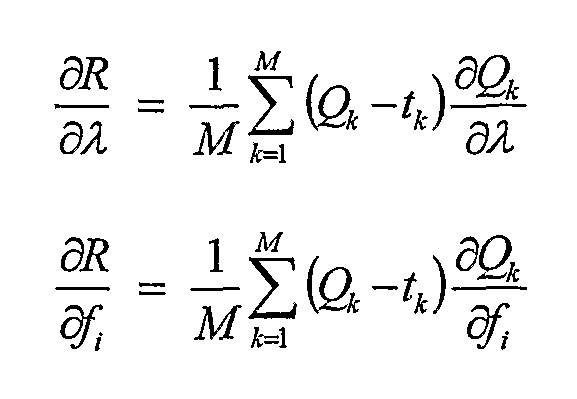
wherein, Qk =Q(xk,λ,f); and can be calculated numerically as, 

Applications Claiming Priority (4)
| Application Number | Priority Date | Filing Date | Title |
|---|---|---|---|
| US65344505P | 2005-02-16 | 2005-02-16 | |
| US60/653,445 | 2005-02-16 | ||
| US11/179,104 US7613758B2 (en) | 2005-02-16 | 2005-07-12 | Method for optimization of Q-Filter kernel parameters |
| US11/179,104 | 2005-07-12 |
Publications (2)
| Publication Number | Publication Date |
|---|---|
| WO2006088569A2 true WO2006088569A2 (en) | 2006-08-24 |
| WO2006088569A3 WO2006088569A3 (en) | 2007-03-22 |
Family
ID=36916900
Family Applications (1)
| Application Number | Title | Priority Date | Filing Date |
|---|---|---|---|
| PCT/US2006/000438 Ceased WO2006088569A2 (en) | 2005-02-16 | 2006-01-05 | Method for optimization of q-filter kernel parameters |
Country Status (2)
| Country | Link |
|---|---|
| US (1) | US7613758B2 (en) |
| WO (1) | WO2006088569A2 (en) |
Cited By (1)
| Publication number | Priority date | Publication date | Assignee | Title |
|---|---|---|---|---|
| US7880607B2 (en) | 2006-12-15 | 2011-02-01 | Motorola, Inc. | Intelligent risk management system for first responders |
Families Citing this family (1)
| Publication number | Priority date | Publication date | Assignee | Title |
|---|---|---|---|---|
| US7656978B2 (en) * | 2006-10-31 | 2010-02-02 | Motorola, Inc. | Fast Q-filter |
Family Cites Families (5)
| Publication number | Priority date | Publication date | Assignee | Title |
|---|---|---|---|---|
| US4438504A (en) * | 1981-06-15 | 1984-03-20 | Bell Telephone Laboratories, Incorporated | Adaptive techniques for automatic frequency determination and measurement |
| US5909384A (en) * | 1996-10-04 | 1999-06-01 | Conexant Systems, Inc. | System for dynamically adapting the length of a filter |
| US6009448A (en) * | 1997-08-18 | 1999-12-28 | Industrial Technology Research Institute | Pipelined parallel-serial architecture for a modified least mean square adaptive filter |
| US6154547A (en) * | 1998-05-07 | 2000-11-28 | Visteon Global Technologies, Inc. | Adaptive noise reduction filter with continuously variable sliding bandwidth |
| GB2375272B (en) * | 2001-04-30 | 2003-11-19 | Lucent Technologies Inc | A frequency estimator for use in a receiver of packetised data, the receiver and a method of reception |
-
2005
- 2005-07-12 US US11/179,104 patent/US7613758B2/en not_active Expired - Fee Related
-
2006
- 2006-01-05 WO PCT/US2006/000438 patent/WO2006088569A2/en not_active Ceased
Cited By (1)
| Publication number | Priority date | Publication date | Assignee | Title |
|---|---|---|---|---|
| US7880607B2 (en) | 2006-12-15 | 2011-02-01 | Motorola, Inc. | Intelligent risk management system for first responders |
Also Published As
| Publication number | Publication date |
|---|---|
| WO2006088569A3 (en) | 2007-03-22 |
| US7613758B2 (en) | 2009-11-03 |
| US20060195499A1 (en) | 2006-08-31 |
Similar Documents
| Publication | Publication Date | Title |
|---|---|---|
| Nazari et al. | Successive variational mode decomposition | |
| US9837991B2 (en) | Adaptive filter for system identification | |
| US7689297B2 (en) | Nonlinear system observation and control | |
| Liu et al. | Design of digital FIR filters using differential evolution algorithm based on reserved genes | |
| CN102169476A (en) | Hilbert-Huang Transform end effect inhibition method based on grey theory | |
| WO2007053831A2 (en) | Optimum nonlinear correntropy filter | |
| CN112764345B (en) | Strong nonlinear system Kalman filter design method based on target state tracking | |
| Pad et al. | Optimality of operator-like wavelets for representing sparse AR (1) processes | |
| WO2006088569A2 (en) | Method for optimization of q-filter kernel parameters | |
| Gnabeyeu | On path-dependent volterra integral equations: Strong well-posedness and stochastic numerics | |
| US7656978B2 (en) | Fast Q-filter | |
| Colburn et al. | A Closed-Form Solution for Kernel Adaptive Filtering | |
| US11610598B2 (en) | Voice enhancement in presence of noise | |
| Koçal | A new approach to least-squares adaptive filtering | |
| Ramirez et al. | Recursive myriad-mean filters: Adaptive algorithms and applications | |
| Bronstein et al. | Blind deconvolution with relative Newton method | |
| Rani et al. | Design and implementation of adaptive filtering algorithm using NLMS having different targets | |
| Hosseini et al. | A novel noise cancellation method for speech enhancement using variable step-size adaptive algorithm | |
| van der Veen et al. | Convergence aspects of step-parallel iteration of Runge-Kutta methods | |
| Siah et al. | Fast parameter optimization using Kriging metamodeling [antenna EM modeling/simulation] | |
| CN101741776A (en) | Method and device for eliminating interference signals | |
| Zhao et al. | A generalized data windowing scheme for adaptive conjugate gradient algorithms | |
| Dewald et al. | IIR filter transient suppression by signal shifting | |
| Leanza et al. | Process uncertainty in Kalman filtering: A novel adaptive filter for vehicle dynamic state estimation | |
| Zhang et al. | A unified framework for least square and mean square based adaptive filtering algorithms |
Legal Events
| Date | Code | Title | Description |
|---|---|---|---|
| 121 | Ep: the epo has been informed by wipo that ep was designated in this application | ||
| NENP | Non-entry into the national phase |
Ref country code: DE |
|
| 122 | Ep: pct application non-entry in european phase |
Ref document number: 06717612 Country of ref document: EP Kind code of ref document: A2 |