WO2006070945A2 - Chemically modified organic polymeric material, and method and apparatus for manufacturing the same - Google Patents
Chemically modified organic polymeric material, and method and apparatus for manufacturing the same Download PDFInfo
- Publication number
- WO2006070945A2 WO2006070945A2 PCT/JP2005/024284 JP2005024284W WO2006070945A2 WO 2006070945 A2 WO2006070945 A2 WO 2006070945A2 JP 2005024284 W JP2005024284 W JP 2005024284W WO 2006070945 A2 WO2006070945 A2 WO 2006070945A2
- Authority
- WO
- WIPO (PCT)
- Prior art keywords
- substrate
- organic polymeric
- polymeric material
- oxygen concentration
- container
- Prior art date
- Legal status (The legal status is an assumption and is not a legal conclusion. Google has not performed a legal analysis and makes no representation as to the accuracy of the status listed.)
- Ceased
Links
Classifications
-
- C—CHEMISTRY; METALLURGY
- C08—ORGANIC MACROMOLECULAR COMPOUNDS; THEIR PREPARATION OR CHEMICAL WORKING-UP; COMPOSITIONS BASED THEREON
- C08J—WORKING-UP; GENERAL PROCESSES OF COMPOUNDING; AFTER-TREATMENT NOT COVERED BY SUBCLASSES C08B, C08C, C08F, C08G or C08H
- C08J7/00—Chemical treatment or coating of shaped articles made of macromolecular substances
- C08J7/12—Chemical modification
-
- H—ELECTRICITY
- H01—ELECTRIC ELEMENTS
- H01M—PROCESSES OR MEANS, e.g. BATTERIES, FOR THE DIRECT CONVERSION OF CHEMICAL ENERGY INTO ELECTRICAL ENERGY
- H01M50/00—Constructional details or processes of manufacture of the non-active parts of electrochemical cells other than fuel cells, e.g. hybrid cells
- H01M50/40—Separators; Membranes; Diaphragms; Spacing elements inside cells
- H01M50/409—Separators, membranes or diaphragms characterised by the material
- H01M50/411—Organic material
- H01M50/414—Synthetic resins, e.g. thermoplastics or thermosetting resins
- H01M50/417—Polyolefins
-
- C—CHEMISTRY; METALLURGY
- C08—ORGANIC MACROMOLECULAR COMPOUNDS; THEIR PREPARATION OR CHEMICAL WORKING-UP; COMPOSITIONS BASED THEREON
- C08J—WORKING-UP; GENERAL PROCESSES OF COMPOUNDING; AFTER-TREATMENT NOT COVERED BY SUBCLASSES C08B, C08C, C08F, C08G or C08H
- C08J7/00—Chemical treatment or coating of shaped articles made of macromolecular substances
- C08J7/12—Chemical modification
- C08J7/16—Chemical modification with polymerisable compounds
-
- H—ELECTRICITY
- H01—ELECTRIC ELEMENTS
- H01M—PROCESSES OR MEANS, e.g. BATTERIES, FOR THE DIRECT CONVERSION OF CHEMICAL ENERGY INTO ELECTRICAL ENERGY
- H01M50/00—Constructional details or processes of manufacture of the non-active parts of electrochemical cells other than fuel cells, e.g. hybrid cells
- H01M50/40—Separators; Membranes; Diaphragms; Spacing elements inside cells
- H01M50/409—Separators, membranes or diaphragms characterised by the material
- H01M50/44—Fibrous material
-
- H—ELECTRICITY
- H01—ELECTRIC ELEMENTS
- H01M—PROCESSES OR MEANS, e.g. BATTERIES, FOR THE DIRECT CONVERSION OF CHEMICAL ENERGY INTO ELECTRICAL ENERGY
- H01M8/00—Fuel cells; Manufacture thereof
- H01M8/10—Fuel cells with solid electrolytes
- H01M8/1016—Fuel cells with solid electrolytes characterised by the electrolyte material
- H01M8/1018—Polymeric electrolyte materials
- H01M8/1058—Polymeric electrolyte materials characterised by a porous support having no ion-conducting properties
- H01M8/106—Polymeric electrolyte materials characterised by a porous support having no ion-conducting properties characterised by the chemical composition of the porous support
-
- H—ELECTRICITY
- H01—ELECTRIC ELEMENTS
- H01M—PROCESSES OR MEANS, e.g. BATTERIES, FOR THE DIRECT CONVERSION OF CHEMICAL ENERGY INTO ELECTRICAL ENERGY
- H01M8/00—Fuel cells; Manufacture thereof
- H01M8/10—Fuel cells with solid electrolytes
- H01M8/1016—Fuel cells with solid electrolytes characterised by the electrolyte material
- H01M8/1018—Polymeric electrolyte materials
- H01M8/1069—Polymeric electrolyte materials characterised by the manufacturing processes
- H01M8/1086—After-treatment of the membrane other than by polymerisation
- H01M8/1088—Chemical modification, e.g. sulfonation
-
- C—CHEMISTRY; METALLURGY
- C08—ORGANIC MACROMOLECULAR COMPOUNDS; THEIR PREPARATION OR CHEMICAL WORKING-UP; COMPOSITIONS BASED THEREON
- C08J—WORKING-UP; GENERAL PROCESSES OF COMPOUNDING; AFTER-TREATMENT NOT COVERED BY SUBCLASSES C08B, C08C, C08F, C08G or C08H
- C08J2323/00—Characterised by the use of homopolymers or copolymers of unsaturated aliphatic hydrocarbons having only one carbon-to-carbon double bond; Derivatives of such polymers
-
- H—ELECTRICITY
- H01—ELECTRIC ELEMENTS
- H01M—PROCESSES OR MEANS, e.g. BATTERIES, FOR THE DIRECT CONVERSION OF CHEMICAL ENERGY INTO ELECTRICAL ENERGY
- H01M2300/00—Electrolytes
- H01M2300/0017—Non-aqueous electrolytes
- H01M2300/0065—Solid electrolytes
- H01M2300/0082—Organic polymers
-
- Y—GENERAL TAGGING OF NEW TECHNOLOGICAL DEVELOPMENTS; GENERAL TAGGING OF CROSS-SECTIONAL TECHNOLOGIES SPANNING OVER SEVERAL SECTIONS OF THE IPC; TECHNICAL SUBJECTS COVERED BY FORMER USPC CROSS-REFERENCE ART COLLECTIONS [XRACs] AND DIGESTS
- Y02—TECHNOLOGIES OR APPLICATIONS FOR MITIGATION OR ADAPTATION AGAINST CLIMATE CHANGE
- Y02E—REDUCTION OF GREENHOUSE GAS [GHG] EMISSIONS, RELATED TO ENERGY GENERATION, TRANSMISSION OR DISTRIBUTION
- Y02E60/00—Enabling technologies; Technologies with a potential or indirect contribution to GHG emissions mitigation
- Y02E60/10—Energy storage using batteries
-
- Y—GENERAL TAGGING OF NEW TECHNOLOGICAL DEVELOPMENTS; GENERAL TAGGING OF CROSS-SECTIONAL TECHNOLOGIES SPANNING OVER SEVERAL SECTIONS OF THE IPC; TECHNICAL SUBJECTS COVERED BY FORMER USPC CROSS-REFERENCE ART COLLECTIONS [XRACs] AND DIGESTS
- Y02—TECHNOLOGIES OR APPLICATIONS FOR MITIGATION OR ADAPTATION AGAINST CLIMATE CHANGE
- Y02E—REDUCTION OF GREENHOUSE GAS [GHG] EMISSIONS, RELATED TO ENERGY GENERATION, TRANSMISSION OR DISTRIBUTION
- Y02E60/00—Enabling technologies; Technologies with a potential or indirect contribution to GHG emissions mitigation
- Y02E60/30—Hydrogen technology
- Y02E60/50—Fuel cells
-
- Y—GENERAL TAGGING OF NEW TECHNOLOGICAL DEVELOPMENTS; GENERAL TAGGING OF CROSS-SECTIONAL TECHNOLOGIES SPANNING OVER SEVERAL SECTIONS OF THE IPC; TECHNICAL SUBJECTS COVERED BY FORMER USPC CROSS-REFERENCE ART COLLECTIONS [XRACs] AND DIGESTS
- Y02—TECHNOLOGIES OR APPLICATIONS FOR MITIGATION OR ADAPTATION AGAINST CLIMATE CHANGE
- Y02P—CLIMATE CHANGE MITIGATION TECHNOLOGIES IN THE PRODUCTION OR PROCESSING OF GOODS
- Y02P70/00—Climate change mitigation technologies in the production process for final industrial or consumer products
- Y02P70/50—Manufacturing or production processes characterised by the final manufactured product
Definitions
- Thepresent invention relates to art for amethodandapparatus for introducing a chemical substance onto an already molded organic polymeric substrate by carrying out a radical-induced chemical reaction, andforaproduct obtainedthroughintroducingthechemical substance, in which it is verified that required functionality is introduced to the substrate by measuring the distribution of the abundance of an introduced desired substance using means enabling analysis ofatomsoratomicgroupsconstitutingthedesiredsubstance in a depth direction from a surface of the product inwards.
- this phenomenon has been observedwithfunctionalities suchas thefollowing: thewettability (contact angle) of the surface of a thin film material onto which hydrophilic functional groups have been introduced; the ionic conduction (diffusion) rate in the film thickness direction of a thin film material onto which ion exchange groups have been introduced; the water absorption rate of a nonwoven fabric onto which hydrophilic functional groups have been introduced; and the metal ion adsorption rate of a nonwoven fabric onto which cation exchange groups have been introduced.
- the present inventors have been the first to discover that, in a region between 1 and 100 nm in a depth direction of a surface layer of a material for which the expected functionality (theoretical value) is not obtained, thereis aregioninwhichtheamountofadesiredsubstanceintroduced in is very low or the desired substance has not been introduced at all.
- the present inventors have further discovered that in the case that there is sucharegion thathas not been chemicallymodified in the depth direction, it is very difficult to verify the presence of this region using a scanning electron microscope (SEM-XMA) or infrared spectroscopy (IR) since these techniques cannot analyze only the region of 1 nm to 100 nra, but rather the presence of this region can only be verified by analyzing the surface using X-ray photoelectron spectroscopy (XPS), a transmission electron microscope (TEM) or the like.
- XPS X-ray photoelectron spectroscopy
- TEM transmission electron microscope
- the present inventors have also discovered that such a region is brought about due to oxygen molecules present in a very smallamountinthesystemduringreaction.
- thepresent inventors have discovered that the above problem can be solved by controllingtheoxygenconcentrationtobe lowerthanconventionally during a process from irradiation with ionizing radiation up to completion of the reaction, thus accomplishing the present invention.
- the present inventors have carried out detailed analysis of materials forwhich the expected functionality (theoretical value) is not obtained, and from the results of analysis of the elemental distribution on the material surface by XPS or TEM, have been the first to discover that in a very narrow region of from 1 nm to 100 nm in the depth direction, there is a region in which little or none of an element originatingfromthe desiredsubstance is present. In the case that this region has a depth of not more than 1 ⁇ m in particular, it is very difficult to find the region through analysis of the elemental distribution using SEM-XMA.
- the present inventors thus carried out introduction of a desired substance while controlling the oxygen concentration in at least one of a radical generation step and a radical-induced reaction step to be lower than conventionally, and analyzed the polymeric material obtained using XPS (or TEM), whereupon it was discovered that a region as described above ceases to be present uponcontrollingtheoxygenconcentrationinthisway.
- the present inventors evaluated functionalities such as the wettability (contact angle) of the surface of a thin film material onto which hydrophilic functional groups have been introduced, the ionic conduction (diffusion) rate in the film thickness direction of a thin film material onto which ion exchange groups have been introduced, the water absorption rate of a nonwoven fabric onto which hydrophilic functional groups havebeen introduced, andthemetal ion adsorption rate of a nonwoven fabric onto which cation exchange groups have been introduced, whereupon it was found that better results than in the case of a conventional method were exhibited.
- an organic polymeric material according to the present invention can be suitably used in various applications.
- the desired substance introduced comprises cationexchangegroups
- the organic polymeric material according to the present invention can be suitably used as a polyelectrolyte film for a polymer electrolyte fuel cell (PEFC) .
- PEFC polymer electrolyte fuel cell
- the organic polymeric material according to the present invention can be suitably used as a polyelectrolyte film for electrodialysis or a separator for a secondary cell.
- the organic polymeric material according to the present invention can be suitably used as a material for removing metal ions.
- FIG. 1 is a drawing showing an example of the constitution of a continuous conveyance type grafting reaction apparatus
- FIG. 2 is a flowchart of an operation control method using measured oxygen concentration values for applying a method of the present invention to a continuous conveyance type reaction process;
- FIG.3 is a conceptual drawing of the operation control method using.measured oxygen concentration values for applying the method of the present invention to the continuous conveyance type reaction process;
- FIG. 4 is a drawing showing the form of a glove box used in the Examples.
- FIG. 5 is a drawing showing the constitution of an ion conductivity measuring apparatus used in the Examples
- FIG. 6 is a graph showing ion conductivity test results for Example 5.
- FIG. 7 is a drawing schematically illustrating a water absorption rate measurement method used in the Examples.
- the present invention relates to a product for which it has been verified that required functionality has been introduced to the substrate by measuring the distribution of the abundance of an introduced desired substance usingmeans enabling analysis of atoms or atomic groups constituting the desired substance in a depth direction from a surface of the product inwards, and a method and apparatus for manufacturing the product.
- the present invention relates to a method of introducing a desired substance giving any of various added functionalities to an organic polymeric substrate by generating radicals through radical-generating means on the organic polymeric substrate, or simultaneously on both the organic polymeric substrate and the desired substance to be introduced, or on the desired substance to be introduced, and carrying out reaction taking the radicals as starting points, so as to form chemical bonds such as covalent bonds, ionic bonds or coordinate bonds, wherein the oxygen concentration is controlled in the radical generation step and/or the radical-induced chemical reaction step.
- the desired substance can be introduced also in a region of from 1 to 100 nm in a depth direction from a surface of the substrate inwards.
- another form of the present invention relates to, for atomic groups constituting a desired substance having functionalityintroducedonto aproductmanufacturedusingtheabove method, measuring the amount of an element constituting the introduced atomic groups in a depth direction from a surface of the product inwards using X-ray photoelectron spectroscopy (XPS) so as to verify the presence of the atomic groups, and thus measuring that a sufficient amount of the atomic groups for the desired application are present on the organic polymeric substrate compared with before the reaction.
- XPS X-ray photoelectron spectroscopy
- any excitingmeans such as heating, ultraviolet radiation, ionizing radiation, alaser, oranionbeammaybeused.
- the excitation source generally has an energy level of not more than 10 "2 eV in the case of heating or in a range of 3 to 10 eV in the case of a commercially available ultraviolet radiation irradiating device, but such an energy level is too low to introduce chemical substances in the depth direction from a surface of the product inwards in the present invention, andmoreover a chemical that assists radical generation such as an initiator may be required.
- a laser or an ion beam does have a sufficient energy level, but is not very desirable for reasons such as the apparatus being complex and expensive, the irradiation area and depth being narrow and shallow and hence there being structural restrictions, and the constituent material being proneto-becomingradioactive.
- Useofionizingradiation is suitable, since the energy level that can be applied is at 10 3 to 10 6 eV, which is sufficientlyhigh comparedwith the bond energy of covalent bonds in the organic polymeric substrate or the desired substance, such ionizing radiation is currently widely used in industry, and an initiator does not have to be used.
- a method for manufacturing an organic polymeric material by chemically modifying an organic polymeric material substrate comprises putting the substrate into container that can be isolated from the outside environment and in which the oxygen concentration can be held lower than that outside, generating radicals on the substrate in part of the container, and then moving the substrate into another part ofthecontainer, andchemicallymodifyingthesubstratethrough a radical-induced reaction, and wherein the oxygen concentration of the atmosphere in which the chemical modification is carried out is in a range of from 1 to 100 ppm.
- a method of manufacturing an organic polymeric material by chemically modifying an organic polymeric material substrate comprises putting the substrate into container that can be isolated from the outside environment and in which the oxygen concentration can be held lower than that outside, generating radicals on the substrate in part of the container, and then moving the substrate into another partofthecontainer, andchemicallymodifyingthe substratethrough a radical-induced reaction, and wherein the oxygen concentration of the atmosphere in which the radicals are generated is in a range of from 1 to 200 ppm.
- a method of manufacturing an organic polymeric material by chemically modifying an organic polymeric material substrate comprises putting the substrate into a container that can be isolated from the outside environment and in which the oxygen concentration can beheldlowerthan that outside, generatingradicals on the substrate in part of the container, and then moving the substrate into another partofthecontainer, andchemicallymodifyingthesubstratethrough a radical-induced reaction, and wherein the oxygen concentration of the atmosphere in which the chemical modification is carried out is in a range of from 1 to 100 ppm, and the oxygen concentration of the atmosphere in which the radicals are generated is in a range of from 1 to 200 ppm.
- the container a single container which is partitioned into a portion in which the radicals are generated on the substrate and a portion in which the chemical modification is carried out.
- the container may comprise a container in which the radicals are generated on the substrate and a separate container in which j thechemicalmodificationiscarriedout, andanapparatuscontaining a connecting section that is isolated from the outside environment and throughwhich the substrate canbemovedwhile holding the oxygen concentration of the atmosphere therein in a range of from 1 to 100 ppm, may be used.
- the container also may comprise a container in which the radicals are generated on the substrate and a separate container in which the chemical modification is carried out, and the method may further comprise moving the substrate from the container in which the radicals are generated to the container in which the chemical modification is carried out via a connecting section that is isolated from the outside environment and through which the substrate can be moved while holding the oxygen concentration of the atmosphere therein in a range of from 1 to 100 ppm.
- a method of manufacturing an organic polymeric material by chemically modifying an organic polymeric material substrate comprises putting the substrate into a container that can be isolated from the outside environment and in which the oxygen concentration can be held lower than that outside, and generating radicals onthe substratewhilebringing the substrate andareactant for the chemical modification into contact with one another in part of the container, and wherein the oxygen concentration of the atmosphere in which the chemical modification is carried out is in a range of from 1 to 100 ppm.
- Radical-induced chemical reaction includes, for example, graft polymerization.
- Oxygen concentration of the atmosphere in which the chemical modification is carried out is preferably in a range of from 1 to 80 ppm, more preferably from 1 to 50 ppm, further preferably from 1 to 30 ppm.
- Oxygen concentration of the atmosphere in which the radicals are generated is preferably in the range of from 1 to 100 ppm, more preferably from 1 to 80 ppm, further preferably from 1 to 50 ppm.
- the substrate may be a sheet-shaped material of a fiber aggregate such as woven or non-woven fabric or a film, and at least one of a step of supplying the substrate into a space in which the reaction is carried out, a step of generating the radicals on the substrate, a step of carrying out the chemical modification on the substrate, and a step of conveying a product out may be carried out continuously.
- a method for holding oxygen concentration of a space in which the chemical modification is carried out or a space in which the radicals are generated in the above range amethod of supplying inert gas of oxygen concentration of the above range or of lower oxygen concentration within the range of from 1 ppb to 100 ppm into the space to thereby replace gas inside the space, may be used.
- a method of supplying inert gas of oxygen concentration of the above range or of lower oxygen concentration within the range of from 0.1 ppm to 100 ppm into the space, thereby exhausting gas in the space, subjecting the exhausted gas to deoxygenation treatment, and then returning the gas into the space, thus carrying out circulation and replacement of the gas in the space may be used.
- Deoxygenation treatment of the gas includes passing the gas through a oxygen adsorption tower or irradiating electron beam to the gas.
- the replacement of the gas or circulation replacement of the gas is preferably conducted continuously during operation of radical generation and chemical reaction.
- the inert gas may be nitrogen gas of purity not less than 99.99%.
- Ionizing radiation that can be used in the present invention includes a neutron beam, cc-rays, ⁇ -rays, ⁇ -rays. X-rays, and an electronbeam.
- a neutron beam cc-rays
- ⁇ -rays ⁇ -rays
- ⁇ -rays ⁇ -rays
- X-rays electronbeam
- withaneutronbeam, ⁇ -rays, ⁇ -raysor ⁇ -rays, a radioisotope must be used, and hence there are constraints on the structure of the irradiating device, and moreover there are strong legal constraints on use.
- X-rays and an electron beam are preferable, since these are widely used in industry, the degree of freedom over the shape of the irradiating chamber is high and hence process design is easy, and thus control of the oxygen concentration in the radical generation step is also easy.
- Theradiation dose is preferably in a range of from 10 to 500 kGy, more preferably from 50 to 200 kGy.
- Asmethodsofradicalgenerationusingradiationinthepresent invention there are a pre-irradiation method in which radicals are generated in the organic polymeric substrate in advance, the organic polymeric substrate is stored such that the radicals that have been generated therein are preserved, and then the organic polymeric substrate in which the radicals have been generated and the desired substance are brought into contact with one another to bring about reaction, and a simultaneous irradiation method in which radicals are generated under the presence of both the organic polymeric substrate and the desired substance.
- Either method can be used in the present invention, or the simultaneous irradiation methodandthepre-irradiationmethodmaybe combinedinacontinuous process.
- the storage temperature is preferably in a range of -196 to 4O 0 C, more preferably -80 to 30 0 C.
- the storage time is preferably from 2 minutes to 6 months, and at a temperature around room temperature of 15 to 30° C is preferably in a range of 1 to 30 minutes.
- the oxygen concentration during the storage is preferably lower thanthe oxygen concentration inatmospheric air, withfrom0.1 to 5% beingsuitable, and from 1 to 200 ppm being preferable, with from 1 to 100 ppm being more preferable, from 1 to 80 ppm being further preferable, and from 1 to 50 ppm being further more preferable.
- Examples of methods of bringing the organic polymeric substrate and the chemical substance into contact with one another when carrying out the radical-induced chemical reaction in the present invention include aliquidphasemethodinwhichthereaction is carried out with the organic polymeric substrate immersed in a solution of the chemical substance, a vapor phase method in which the reaction is carried out by bringing the organic polymeric substrate into contact with a vapor of the chemical substance, an impregnation vapor phase method in which the organic polymeric substrate is immersed in a solution of the chemical substance, and then the organic polymeric substrate is taken out from the solution and reaction is carried out in the vapor phase using solution of thechemical substanceremainingintheorganicpolymeric substrate, and a coating method in which a solution containing the chemical substance or a solid containing the chemical substance is coated onto a surface of the organic polymeric substrate so as to bring about reaction; any of these methods can be suitably used.
- the method of controlling the oxygen concentration in the radical generation step for example one of the following methods can be adopted: a method in which the organic polymeric substrate piece is put into a container (hereinafter referred to as an "irradiating container") made of a material having an oxygen permeability coefficient of not more than 10 "5 mol-cm/m 2 *sec-Pa, and then the gas inside the container is replaced with an inert gas such as nitrogen or argon; a method in which an irradiating chamber of an irradiating device is made to have a structure surroundedbyawall able to isolate the irradiating chamber from atmospheric air, and the irradiating chamber has an inert gas introduced therein and is exhausted so as to replace air in the irradiating chamber with the inert gas; and amethod in which the interior of an irradiating container is exhausted so as to reduce the pressure in the irradiating container and thus reduce the oxygen partial pressure in the irradiating container.
- the method of measuring the oxygen concentration for example one of the following methods can ' be adopted: a method in which when replacing the gas inside an irradiating container, the replacement is carried out in a glove box into which the inert gas has been introduced, and the oxygen concentration in the glove box is measured using oxygen concentration measuring means; a method in which the pressure in the irradiating container is measured and the oxygen concentration is calculated from the oxygen partial pressure; and a method in whichtheoxygenconcentrationinanirradiatingchamberismonitored using oxygen concentration measuring means connected by a sampling pipe made of a material having an oxygen permeability coefficient of not more than 10 "5 mol-cm/m 2# sec-Pa (e.g. stainless steel.
- the oxygen concentration in the radical generation step is in a range of from 1 to 200 ppm in the present invention, with from 1 to 100 ppm being preferable, from 1 to 80 ppm being more preferable, and from 1 to 50 ppm being further more preferable.
- oxygen concentration in a container is continuously monitored during operation of irradiation by means of the above mentioned oxygen concentration measuring means, and when the oxygen concentration approaches the freely chosen set value (upper limit of the predetermined oxygen concentration range) , flow rate of the inert gas introduced into the container may be increased by opening/closing a solenoid valve or the like in accordance with the way in which the oxygen concentration approaches the set value, whereby the oxygen concentration can be maintained within the predetermined range.
- the same method as for the radical generation step maybe used.
- amethod in which the irradiated organic polymeric substrate and a solution of thechemical substanceare introducedintoandsealedinareaction vessel in a glove box as above while measuring the oxygen concentration may also be used.
- the oxygen concentration in the chemical reaction step is preferably in a range of from 1 tolOO ppm, with from 1 to 80 ppm being preferable, from 1 to 50 ppm being more preferable, and from 1 to 30 ppm being further more preferable.
- the same method as in the radical generation step mentioned above may be used.
- a continuous conveyance type reaction process as proposed by the present inventors (U.S. Patent No. 6,659,751) can be used.
- the descriptions in U.S. Patent No. 6,659,751 are incorporated herein by reference.
- An example of the constitution of such a continuous conveyance type reaction process is shown in FIG. 1.
- the continuous conveyance type reaction process is for carrying out radical generation using a pre-irradiation method, and then bringing about reaction by bringing a roll-shaped organic polymeric substrate and a chemical substance into contact with one anotherusing an impregnationvaporphasemethod, and is constituted fromfour steps as pivotal elements, whichcan also beusedin another system.
- First is arolling out step inwhich the roll-shapedorganic polymeric substrate is rolled out and thus continuously supplied in; secondisanionizingradiationirradiationstepinwhichradicals are generated in the rolled out organic polymeric substrate; third is achemicalreaction step inwhichthe irradiatedorganicpolymeric substrate and the chemical substance are brought into contact with one another to bring about a radical-induced chemical reaction; and fourth is arolling up step inwhich the product obtained through the reaction is rolled back up into the form of a roll to finish.
- chemical reaction step may be divided into an impregnation step where substrate is impregnated with chemical substance and a reaction step where radical-induced chemical reaction is proceeded.
- an internal circulating device such as a fan may be installed in the devices. Replacement of gas inside is preferably conducted continuously. In each device where each of the above mentioned step is conducted (in Fig.
- oxygen concentration can be maintained within the predetermined range by attaching oxygen concentration meter to the each device, and continuously monitoring oxygen concentration in the device, and when the oxygen concentration approaches the freely chosen set value (upper limit of the predetermined oxygen concentration range) , increasing flow rate of the inert gas introduced into the container by opening/closing a solenoid valve or the like in accordance with the way in which the oxygen concentration approaches the set value.
- connecting sections between the devices that carry out the respective steps may also have a structure surrounded by a wall that isolates the inside thereof from atmospheric air, or a sealing structure or the like may be provided at the connecting sections to thereby keep each device separate airtight condition, whereby an effect of it being possible to reduce the amount of the inert gas used can be expected, and additionallyaneffect ofitbeingpossibletomaintainpredetermined oxygen concentration for each device can also be expected.
- a sealing structure is that in Japanese Patent Application No. 2004-203507, which is a prior patent case from the present inventors. The descriptions in Japanese Patent Application No. 2004-203507 are incorporated herein by reference.
- Asthemethodofmeasuringtheoxygenconcentrationinsidethedevices in the present invention as with the irradiating chamber, a method in which the oxygen concentration is monitored using oxygen concentration measuring means connected using a sampling pipe made of a material having an oxygen permeability coefficient of not more than 10 "5 mol-cm/m 2 -sec-Pa (e.g. stainless steel. Teflon (registered trademark), nylon, etc. ) canbeadopted.
- the monitoring of the oxygen concentration may be carried, out continuously.
- the present invention also relates to an apparatus for conducting a method, of the present invention as explained above totherebyproduceachemicallymodifiedorganicpolymericmaterial .
- another embodiment of the present invention relates to an organic polymeric material chemical modification apparatus for manufacturing a film-shaped organic polymeric material by chemically modifying an organic polymeric material substrate, the apparatus comprising: an ionizing radiation irradiating section that is disposed in a first container that isolates the substrate from the outside environment and in which the oxygen concentration can be held lower than that outside, and is for generating radicals on the organic polymeric material substrate; a chemical modification section that is disposed in a second container that isolates the substrate from the outside environment and in which the oxygen concentration can be held lower than that outside, and is for carrying out chemical modification through a reaction induced by the radicals; and a connecting section that is disposed in a third container that isolates the substrate from the outside environment and in which the oxygen concentration can be held lower than that outside, and connects the container in which the ionizing radiation irradi
- the chemical modification section may be divided into impregnation section and reaction section, and each section may bedisposedinseparatecontainerandthecontainersmaybeconnected by a connecting section.
- both of the container in which impregnation section is disposed and the container in which reaction section is disposed have a mechanism to hold the oxygen concentration of the gas in the container in a range of from 1 ppm to 100 ppm.
- an ionizing radiation irradiating section, an chemical modification section and a conveyance section may be disposed in one container.
- another embodiment of the present invention relates to an organic polymeric material chemical modification apparatus for manufacturing a film-shaped organic polymeric material by chemically modifying an organic polymeric material substrate, the apparatus comprising: a container that isolates the substrate from the outside environment and in which the oxygen concentration can be held lower than that outside; an ionizing radiation irradiating section that is disposed in the container, and is for generating radicals on the organic polymeric material substrate; a chemical modification section that is disposed in the container, and is for chemically modifying the substrate through a reaction induced by the radicals; and a conveyance section that is disposed in the container, and is for conveying the substrate from the ionizing radiation irradiating section into the chemicalmodification section, wherein the container is provided with an inert gas supply port for supplying an inert gas into the container, and an exhaust port for exhausting gas from the container, and wherein
- the mechanism to hold oxygen concentration of gas inside the container in the predetermined range for example, a system in which oxygen concentration meter is attached to the container, and oxygen concentration in the container is continuously monitored, and when the oxygen concentration approaches the freely chosen set value
- the organic polymeric material chemical modification apparatuses as mentioned above may further comprises an oxygen concentration meter that continuously monitors the oxygen concentration of the gas in the ionizing radiation irradiating section and/or the chemical modification section, and further comprises a warning device for issuing a warning if the oxygen concentration deviates from a prescribed concentration range.
- the apparatus may further comprises an oxygen concentration meter that continuously monitors the oxygen concentration of the gas in the ionizing radiation irradiating section and/or the chemical modification section, and further comprises a shutdown device for stoppingtheirradiationwiththeionizingradiationand/orstopping the chemical modification reaction if the oxygen concentration deviates from a prescribed concentration range.
- the apparatuses may further comprises an oxygen concentration meter that monitors the oxygen concentration of the gas in the ionizing radiation irradiating section and/or the chemical modification section, and further comprises a control device for controlling commencement of operation of the apparatus to be operational when the oxygen concentration of the gas in each of the ionizing radiation irradiating section and the chemical modification section is within a prescribed concentration range.
- the present invention also relates a program for operating the apparatus as explained above.
- another embodiment of the present invention relates a computer-readable apparatus operation program for the organic polymeric material chemical modification apparatus as explained above, for implementing a step of making the oxygen concentration of the gas in each of the ionizing radiation irradiating section, the chemical modification section and the connecting section be within a prescribed concentration range by replacing the gas in each of the ionizing radiation irradiating section, the chemical modification section and the connecting sectionwith an inert gas inwhich the oxygen concentration is within a prescribed concentration range, a step of moving a substrate that hasbeenconveyedinfromasubstrate supplysectionintotheionizing radiation irradiating section, and irradiating the substrate with aprescribedamountofionizingradiationbyadjustinganirradiation source and the irradiation time, thus generating radicals on the substrate, a step of moving the substrate on which the radicals havebeengeneratedinto thechemicalmodificationsection, bringing the substrate into contact
- the program may further comprise a program unit for implementing the step of issuing a warning if the oxygen concentration deviates from a prescribed concentration range.
- the program may further comprise a program unit for implementing the step of stopping the irradiationwiththeionizingradiationand/orstoppingthechemical modification reaction if the oxygen concentration deviates from aprescribed concentration range.
- the program may further comprise aprogramunit for implementing the step of controlling commencement of operation of the apparatus to be operational when the oxygen concentrationofthegas ineachoftheionizingradiationirradiating section and the chemicalmodification section is within aprescribed concentration range.
- the reaction time used in the radical-induced chemical reaction step varies depending on the combination of the organic polymeric substrate and the chemical substance, but from 5 minutes to 24 hours is suitable, preferably 10 minutes to 6 hours, more preferably 15 minutes to 2 hours.
- the reaction temperature used in this step maybe anytemperature from -20° Cup to the decomposition temperature of the chemical substance, but from 20 to 120 0 C is suitable, preferably 30 to 80 0 C, more preferably 40 to 70 0 C.
- Oxygen concentration measuring means used in the present invention may be any commercially available oxygen concentration meter, but it must be possible to measure oxygen concentrations below 100 ppm.
- Types include a magnetic type (POM6E made by Japan Air Gases Ltd., ZKG made by Fuji Electric Instruments Co., Ltd., etc. ) , a zirconia type (LC-750 made by Toray Engineering Co. , Ltd. , IS-700 made by IijimaElectronics Corporation, etc. ) , and a galvanic type (MC-7G made by Iijima Electronics Corporation, MKI-50 made by Japan Air Gases Ltd, etc. ) .
- the magnetic type lacks sensitivity.
- the sample gas from the chemical reaction step may contain flammable gas, in which case the oxygen concentration cannot be measured accurately using the zirconia type.
- the galvanic type which has a sufficient oxygen concentration measurement range, and for which there are no problems with the measurement even if the sample gas contains flammable gas, is thus suitable.
- a cold trap, a mist separator or the like can be installed in the gas sampling pipe so as to extend the lifetime of the oxygen concentration meter.
- the dissolved oxygen concentration in the solvent must be reduced by aerating the solvent with an inert gas before use, and it is preferable to measure the dissolved oxygen concentration using oxygen concentration measuring means.
- the dissolved oxygen concentration in the reaction solvent used in the present invention is preferably in a range of from 0.1 to 8 ppm, with from 0.1 to 4 ppm being suitable, and from 0.1 to 1 ppm being more preferable.
- the reaction solution that has been aerated with the inert gas can be fed into the piping so as to force out gas residing in the piping, thus preventing from getting into the device from the piping. More preferably, a method can be adopted in which the gas in the piping is replaced with an inert gas, and then the reaction solution is fed in.
- any organic polymeric material from which radicals can be generated can be used; for example, polyolefin resins, halogenated polyolefin resins, and so on, which are easily shaped and are widely distributed, are suitable, with it beingeasytousepolyethylene andpolypropylene, whicharewidely usedplastics, andfluororesins (Teflon (registeredtrademark) made byMitsui DuPont Fluorochemicals, the NeofIon series madebyDaikin, etc.)f which are engineering plasties.
- a polyvinyl alcohol resin (Bovlonmade byNippon Synthetic Chemical IndustryCo. , Ltd. , etc.
- a polyvinyl alcohol-ethylene copolymer resin (Eval made by Kuraray Co., Ltd., etc.), a polyvinyl chloride resin, a polyester resin, a nylon resin, or the like
- An organic polymeric substrate of any form may be used, for example granules, a rod-like form, a woven fabric or nonwoven fabric, a film or sheet, fibers or yarn, hollow fibers, a straw-like form, or a foam.
- a form that can be put into a roll is most suitable.
- Aschemicalsubstances thatcanbeusedinthepresentinvention and made to undergo the radical-induced chemical reaction with the organic polymeric substrate for example any polymerizable monomer having a carbon-carbon double bond therein can be used.
- Examples includepolymerizablemonomers having functional atomicgroups such as ion exchange groups or hydrophilic groups, for example (meth)acrylic acid, sodiumstyrenesulfonate, sodiumvinylsulfonate, vinylbenzyltrimethylammonium chloride, diethylaminoethyl methacrylate, acrylamide, hydroxyethyl methacrylate, N-vinylacetamide, andN-vinylpyrrolidone.
- the desired substance can be introduced onto the organic polymeric substrate through only the chemical reaction step.
- a polymerizable monomer that does not itself have the desired functional atomic groups but instead has atomic groups that constitute a precursor able tobe convertedinto the desiredsubstance throughanadditional subsequent step, carry out the radical-induced chemical reaction accordingtothepresentinvention, andthenuseaprescribedchemical to form the product having the desired substance thereon.
- polymerizable monomers for which this method can be used include glycidyl methacrylate, styrene, chloromethylstyrene, and vinyl acetate.
- glycidyl methacrylate onto the organic polymeric substrate as polymer side chains through a radical-induced chemical reaction, and then, for example, react with dimethylamine or iminodiethanol so as to form aproducthavingweaklybasicaminogroups onthepolymersidechains.
- styrene onto the organic polymeric substrate as polymer side chains, and then carry out a sulfonation reaction with a chlorosulfonic acid solution or the like so as to introduce cation exchange groups.
- Anexampleofanoperationcontrolmethodusingmeasuredoxygen concentrationvaluesforapplyingthemethodaccordingtothepresent invention to a continuous conveyance type reaction process includes a method for which a flowchart is shown in FIG. 2 and a conceptual drawing of an example of the application is shown in FIG. 3.
- a freely chosen threshold value foranoxygenconcentrationrangethat is tobemaintained is inputted into an oxygen concentration meter as a set value, a signal is outputted if the oxygen concentration exceeds the set value, the signal is received by a control console of the irradiating device or the reactor, andawarning is issued, oroperationof the apparatus is stopped.
- a method in which only the measured oxygen concentration value is sent from the oxygen concentration meter to the control console, this measured oxygen concentration valueis comparedwithafreelychosensetvaluethathasbeeninputted into the control console in advance, and a warning is issued or operation is stopped if the measured oxygen concentration value exceeds the set value may also be adopted; either of these systems canbe selected.
- stopping operation it is preferable to stop the irradiation, and then stop operation of the reactor once it has been verified that the irradiation has been stopped. This is to prevent deformation or breakage of the organic polymeric substrate throughexcessive irradiationwith the ionizingradiation.
- setup may be carried out such that operation of the apparatus can only be commenced when the oxygen concentration is below the freely chosen set value, in which case operational misses can be prevented.
- the oxygen concentration in each of the devices can also be held constant using the measured oxygen concentration value.
- the flow rate of the inert gas introduced into each of the devices may be changed to a preset flow rate by opening/closing a solenoidvalveorthe likewhenthe oxygen concentrationapproaches the freely chosen set value, this being in accordance with the way in which the oxygen concentration approaches the set value, whereby the oxygen concentration range can be kept from exceeding the set value.
- the chemically-modified organic polymeric material obtainable by a method of the present invention includes the following.
- An organic polymeric material comprising a chemically modified organic polymeric material substrate, wherein a response due to the chemical modification is detected by X-ray photoelectron spectroscopy (XPS) for a surface layer of the substrate.
- XPS X-ray photoelectron spectroscopy
- organic polymeric material according to any of the above items 1 to 3, wherein the organic polymeric material is a film-shaped organic polymeric material comprising a chemically modified film-shaped organic polymeric material substrate.
- the film-shaped organic polymeric material comprising a chemically modified film-shaped organic polymeric material substrate according to the above item 4, wherein a region of from 0.02 to 0.5% of the film thickness in a depth direction of a surface layer of the substrate is chemically modified.
- An organic polymeric material comprising a fiber or an assembly of fibers obtained by chemically modifying an organic polymericmaterialsubstratehavingtheformof afiberoranassembly of fibers, wherein a response due to the chemical modification is detected by X-ray photoelectron spectroscopy (XPS) for a surface layer of the substrate.
- XPS X-ray photoelectron spectroscopy
- the organic polymeric material comprising a fiber or an assembly of fibers obtained by chemically modifying an organic polymericmaterial substratehavingtheformof afiberoranassembly of fibers according to the above item 8 or 9, wherein from 0.02 to 0.5% of the fiber diameter in a depth direction of a surface layer of the fibrous substrate is chemically modified.
- XPS X-ray photoele ⁇ tron spectroscopy
- a battery separator for secondary cell comprising the organic polymeric material according to any of the above items 1 through 16 obtained by introducing ion exchange groups onto the organic polymeric material substrate, wherein the ion exchange groups are introduced through reaction including a radical-induced chemical reaction.
- a battery separator for secondary cell comprising an organic- polymeric material substrate having ion exchange groups introduced thereon, wherein a response due to the introduction of the ion exchange groups is detected by X-ray photoelectron spectroscopy (XPS) for a surface layer of the substrate.
- XPS X-ray photoelectron spectroscopy
- the surface layer of the substrate means surface layer of the fiber which forms the substrate.
- asmeans formeasuringtheatomic groups or some of the atoms constituting the introduced desired substance in the depth direction from the surface of the product inwards for example there are a total reflectionmeasurementmethod using Fourier transform infrared spectroscopy in which measurement is carried out by changing the angle of incidence of the infrared rays, amethodusingatransmission electronmicroscope, and amethod using X-ray photoelectron spectroscopy.
- X-ray photoelectron spectroscopy is particularly suitable for analyzing the distribution of some of the atoms constituting the desired substance in a range of from 1 to 100 nm in the depth direction from the surface oftheproductinwardsinthepresentinvention.
- X-rayphotoelectron spectroscopy is a method in which, for example, in measurement on an organic polymer or the like, etching is carried out using Ar ions or the like so as to etch away the material from the surface, during which qualitative or quantitative information on atoms present in the vicinity of the etching position can be obtained.
- measurementontheamountpresentof sulfur atoms contained in the sulfonic acid groups can be obtained by irradiating X-rays in the depth direction from the surface of the product inwards, and measuring the energy of secondary electrons that are excited and thus jump out and the number of these secondary electrons at eachenergy, wherebythenumberof sulfuratoms present, or the state of bonding of these sulfur atoms to other atoms, in a region from the surface inwards can be obtained.
- the results of such measurement can be compared with the required amount of functional atomic groups in accordance with the desired use, and thus used in product quality management.
- Example 1 The interior of a glove box as shown in FIG. 4 was put under a nitrogen atmosphere, the oxygen concentration was continuously measuredusing agalvanic cell type oxygen concentrationmeter (made by Iijima Electronics Corporation, model number MC7G-L) as oxygen concentration measuring means, and with the oxygen concentration held in the range of more than 5 ppm and less than 30 ppm, 0.87 g (100 mm x 150 mm) of a poly(chlorotrifluoroethylene) resin film (Neoflon made by Daikin, mean film thickness 25 ⁇ m, mean weight 55 g/m 2 ) was put into a polyethylene bag.
- agalvanic cell type oxygen concentrationmeter made by Iijima Electronics Corporation, model number MC7G-L
- the polyethylene bag with the film therein was taken out from the glove box, and was irradiatedwitha200kGyelectronbeam.
- Amixedliquidofstyrene monomer (70 ml) and toluene (30 ml) was aerated with nitrogen gas under an oxygen concentration of 10 ppm in the glove box for 30 minutes.
- the irradiated filmand the aeratedmixed liquid were then put into a glass vessel under an oxygen concentration in the range of more than 5 ppm and less than 10 ppm in the glove box, the glass vessel was sealed, and graft polymerization was carried out for 2 hours at 60° C.
- the grafted film was taken out, removal of homopolymer was carried out for 2 hours using a Soxhlet extractor with acetone as an extraction solvent, and then drying was carried out for 30 minutes at 70°,C, whereby 1.15 g of a styrene-grafted film was obtained.
- the graft rate as determined from the weight change was 32.2%.
- the grafted film obtained was immersed in a mixed liquid of chlorosulfonic acid / dichloromethane in a weight ratio of 2 / 98, and sulfonation was carried out for 2 hours at 5 0 C.
- Example 2 0.88 g (100 mm x 150 mm) of the same poly(chlorotrifluoroethylene) resin film as that used in Example 1 was put into a polyethylene bag under a nitrogen atmosphere with an oxygen concentration in the range of more than 10 ppm and less than 25 ppm in a glove box like that used in Example 1, and the polyethylene bag with the film therein was taken out from the glove box, andwas irradiatedwitha 200 kGyelectronbeam.
- the irradiated film, and a mixed liquid of styrene monomer (70 ml) and toluene (30 ml) that had been aerated with nitrogen gas for 30 minutes were then put into a glass vessel under an oxygen concentration in the range of more than 100 ppm and less than 110 ppm in the glove box, the glass vessel was sealed, and graft polymerization was carried out for 2 hours at 60 0 C.
- the grafted film was then taken out, removal of homopolymer was carried out for 2 hours using a Soxhlet extractor with acetone as an extraction solvent, and then drying was carried out for 30 minutes at 7O 0 C, whereby 1.12 g of a styrene-grafted film was obtained.
- the graft rate as determined from the weight change was 27.3%.
- the grafted film obtained was immersed in a mixed liquid of chlorosulfonic acid / dichloromethane in a weight ratio of 2 / 98, and sulfonation was carried out for 2 hours at 5° C.
- the film was then taken out, washed successively with a mixed liquid of methanol / dichloromethane in a weight ratio of 10 /90, methanol, and then pure water, and then dried, whereby a sulfonated film B having an ion exchange capacity of 168 meq/m 2 was obtained.
- a polyethylene fiber nonwoven fabric made by DuPont-Asahi Flash Spun Products Co. , Ltd. , trade name Tyvek, mean fiber diameter 0.5 to 10 ⁇ m, weight 65 g/m 2 , thickness 0.17 mm, 300 mm wide x 200 m long roll
- Tyvek mean fiber diameter 0.5 to 10 ⁇ m
- weight 65 g/m 2 weight 65 g/m 2
- thickness 0.17 mm 300 mm wide x 200 m long roll
- the oxygen concentration was continuously measured using a galvanic cell type oxygen concentration meter (made by Japan Air Gases Ltd.
- the nonwoven fabric was irradiated with a 150 IcGy electron beam.
- Chloromethylstyrene (CMS-AM made by Seimi Chemical Co., Ltd.) was treated with basic alumina to adsorb and thus remove the polymerization inhibitor therein, and then toluene was added to prepare a chloromethylstyrene / toluene (weight ratio 80 / 20) solution, and after aerating with nitrogen for 30 minutes, the solution was introduced into the impregnator.
- the irradiatednonwoven fabric obtainedas described above was conveyed into the impregnator at a rate of 0.6 m/min and impregnated with the solution, and was then conveyedinto the reactor and subjected to graft polymerization for 40 minutes at 60° C.
- the nonwoven fabric samples were then washed with acetone, and then dried for 2 hours at 60 0 C, whereby chloromethylstyrene-grafted nonwoven fabric samples were obtained.
- the graft rate as determinedfromthe change in theweight of each of the samples obtained is shown in Table 1.
- the mean graft rate was 47.
- Example 2 An impregnation vapor phase graft polymerization reaction was carried out as in Example 2 using the same polyethylene fiber nonwoven fabric as that used in Example 2. Specifically, with the oxygen concentration in the irradiating chamber held at 250 ppm, the nonwoven fabric was irradiated with a 150 kGy electron beam. A purified chloromethylstyrene (CMS-AM made by Seimi Chemical Co. , Ltd.) / toluene (weight ratio 80 / 20) solution was aerated with nitrogenfor30minutes, andwasthenintroducedintotheimpregnator.
- CMS-AM chloromethylstyrene
- toluene weight ratio 80 / 20
- the irradiated nonwoven fabric was conveyed into the impregnator at a rate of 0.6 m/min and impregnatedwith the solution, and was then conveyed into the reactor and subjected to graft polymerizationfor 40minutes at 60° C.
- Samples of sizeproductwidth x 300 mm were cut out at three points at 80 m intervals in the length direction of the grafted nonwoven fabric thus manufactured, and the samples were treated for 3 hours at 60° C in toluene so as to removehomopolymertherefrom.
- Thenonwovenfabricsamples werethen washed with acetone, and then dried for 2 hours at 60 0 C, whereby chloromethylstyrene-graftednonwovenfabric sampleswereobtained.
- the graft rate as determined from the change in the weight of each of the grafted nonwoven fabric samples obtained is shown in Table 3.
- the mean graft rate was 45.6%. Table 3
- each of the chloromethylstyrene-grafted nonwoven fabric samples obtained was immersed in a mixed liquid of isopropanol / 30% trimethylamine aqueous solution / pure water in a volume ratio of 30 / 30 / 40, and reaction to form a quaternary ammoniumsaltwascarriedoutfor6hoursat 60° C.
- Eachofthenonwoven fabric samples was then taken out, washed three times with pure water at 40 0 C, and then dried for 1 hour at 50 0 C, whereby anion exchange type nonwoven fabric samples D were obtained.
- the ion exchange capacity of each of the nonwoven fabric samples D obtained is shown in Table 4.
- the mean ion exchange capacity was 176 meq/m 2 .
- Example 3 The interior of a glove box as shown in FIG. 4 was put under a nitrogen atmosphere, the oxygen concentration was continuously measuredusing a galvanic cell type oxygen concentrationmeter (made by Iijima Electronics Corporation, model number MC7G-L) as oxygen concentration measuring means, and with the oxygen concentration held in the range of more than 5 ppm and less than 30 ppm, 3.94 g (200 mm x 300 mm) of a polyethylene fiber nonwoven fabric (made by DuPont-Asahi Flash Spun Products Co. , Ltd. , trade name Tyvek, mean fiber diameter 0.5 to 10 ⁇ m, weight 65 g/m 2 , thickness 0.17 mm) was put into a polyethylene bag.
- a galvanic cell type oxygen concentrationmeter made by Iijima Electronics Corporation, model number MC7G-L
- MC7G-L oxygen concentration measuring means
- the polyethylene bag with the nonwoven fabric therein was then taken out from the glove box, and was irradiated with a 150 kGy electron beam.
- a solution of lithium p-styrenesulfonate (made by Tosoh Corporation, trade name LiSS) in ethanol (weight ratio: 1/19) was aerated with nitrogen gas under an oxygen concentration of 10 ppm in the glove box for 30 minutes.
- the irradiated nonwoven fabric obtained as described above was immersed in the aerated solution, then liquid was wiped off from the nonwoven fabric to make the total weight 7.80 g, and then the nonwoven fabric was put into a glass vessel under an oxygen concentration in the range of more than 5 ppm and less than 10 ppm in the glove box, the glass vessel was sealed, and graft polymerization was carried out for 3 hours at 60 0 C.
- the grafted nonwoven fabric was taken out, removal of homopolymer was carried out by washing with pure water at 60 0 C, and then the water was wiped off, and drying was carried out for 1 hour at 50° C, whereby4.22 gofalithiumstyrenesulfonate-graftednonwovenfabric was obtained.
- the graft rate as determined from the weight change was 7.1%.
- the grafted nonwoven fabric obtained was washed twice with 0.5 mol/L hydrochloric acid (500 ml), and was then washed twice with pure water (500 ml) at 60 0 C, and then the water was wiped off, and drying was carried out for 1 hour at 50 0 C, whereby a 4.19 g cation exchange type nonwoven fabric E was obtained.
- the nonwoven fabric E obtained had an ion exchange capacity of 10.1 meq/m 2 .
- Comparative Example 3 3.89 g (200 mm x 300 mm) of a polyethylene fiber nonwoven fabric (made by DuPont-Asahi Flash Spun Products Co., Ltd., trade nameTyvek, meanfiberdiameter0.5 to 10 ⁇ m, weight 65 g/m 2 , thickness 0.17 mm) was introduced into a polyethylene bag under a nitrogen atmosphere with an oxygen concentration in the range of more than 10 ppm and less than 25 ppm in a glove box like that used in Example 1, and the polyethylene bag with the nonwoven fabric therein was irradiated with a 150 kGy electron beam.
- a polyethylene fiber nonwoven fabric made by DuPont-Asahi Flash Spun Products Co., Ltd., trade nameTyvek, meanfiberdiameter0.5 to 10 ⁇ m, weight 65 g/m 2 , thickness 0.17 mm
- the irradiated nonwoven fabric was then immersedin a solution of lithiump-styrenesulfonate in ⁇ thanol (weight ratio: 1/19) that had been aerated with nitrogen gas for 30 minutes, then liquid was wiped off to make the total weight 7.80 g, and then the nonwoven fabric was put into a glass vessel under an oxygen concentration in the range of more than 100 ppm and less than 110 ppm in the same glove box used in Example 1, the glass vesselwas sealed, and graft polymerization was carried out for 3 hours at 60° C.
- the grafted nonwoven fabric was then taken out, removal of homopolymer was carried out by washing with pure water at 6O 0 C, and then the water was wiped off, and drying was carried out for 1 hour at 50 0 C, whereby 4.16 g of a lithium styrenesulfonate-grafted nonwoven fabric was obtained.
- the graft rate as determined from the weight change was 6.9%.
- the grafted nonwoven fabric obtained was washed twice with 0.5 mol/L hydrochloric acid (500 ml), and was then washed twice with pure water (500 ml) at 60 0 C, and then the water was wiped off, and drying was carried out for 1 hour at 50 0 C, whereby a 4.13 g cation exchange type nonwoven fabric F was obtained.
- the nonwoven fabric F obtained had an ion exchange capacity of 9.8 meq/m 2 .
- Example 4 The sulfonatedfilmAproducedinExample 1, andthe sulfonated film B produced in Comparative Example 1 were each subjected to measurement of the elemental distribution on the surface thereof using XPS.
- Example 6 Sulfonated films A and B obtained in Example 1 and Comparative Example 1 and Nafion (Trademark) Nl15 made by DuPont were subjected to measurement of the voltage under a constant current using an ion conductivity measuring apparatus as shown in FIG. 5, whereby the ion conductivity was measured. The results are shown in FIG. 6 as a graph in which the horizontal axis shows the current, and the vertical axis shows the voltage required under the constant current, which indicates the ion conductivity. From these results, it can be seen that the ion conductivity is better if the oxygen concentration during the reaction is lower.
- FIG.2 isaflowchartofanoxygenconcentrationcontrolmethod
- FIG. 3 is a conceptual drawing of an example of application of this'method to a continuous conveyance type grafting reaction apparatus.
- test operation was carried out with an oxygen concentration set value of 200 ppm on the irradiating devicesideand50ppmonthereactorside. Commencementofoperation was not possible if either of these set values was exceeded, trial operation was commenced once the oxygen concentration was below the set values, and if the oxygen concentration rose, then a warning was issued by means of a buzzer and a Patlite (registered trademark) coming on, and a warning message was displayed on a control console touch panel. In this case, the irradiation was stopped, and then conveyance was stopped.
- a Patlite registered trademark
Landscapes
- Chemical & Material Sciences (AREA)
- General Chemical & Material Sciences (AREA)
- Chemical Kinetics & Catalysis (AREA)
- Electrochemistry (AREA)
- Manufacturing & Machinery (AREA)
- Engineering & Computer Science (AREA)
- Sustainable Energy (AREA)
- Sustainable Development (AREA)
- Life Sciences & Earth Sciences (AREA)
- Health & Medical Sciences (AREA)
- Medicinal Chemistry (AREA)
- Polymers & Plastics (AREA)
- Organic Chemistry (AREA)
- Treatments Of Macromolecular Shaped Articles (AREA)
- Addition Polymer Or Copolymer, Post-Treatments, Or Chemical Modifications (AREA)
- Analysing Materials By The Use Of Radiation (AREA)
Abstract
It is an object of the present invention to clarify the phenomenon that causes the functionality expected based on the amount of the desired substance introduced and so on to not be obtained when synthesizing a functional material by carrying out a radical-induced chemical reaction so as to introduce a desired substance onto an organic polymeric substrate. It is also an object of the present invention to provide a functional material, and a method and apparatus for synthesizing the same, according to which such a phenomenon is avoided. In one aspect of the present invention, there is provided an organic polymeric material comprising a chemically modified organic polymeric material substrate, wherein a response due to the chemical modification is detected by X-ray photoelectron spectroscopy (XPS) for a surface layer of the substrate..
Description
DESCRIPTION
CHEMICALLY MODIFIED ORGANIC POLYMERIC MATERIAL, AND METHOD AND APPARATUS FOR MANUFACTURING THE SAME
BACKGROUND OF THE INVENTION Field of the Invention
Thepresent inventionrelates to art for amethodandapparatus for introducing a chemical substance onto an already molded organic polymeric substrate by carrying out a radical-induced chemical reaction, andforaproduct obtainedthroughintroducingthechemical substance, in which it is verified that required functionality is introduced to the substrate by measuring the distribution of the abundance of an introduced desired substance using means enabling analysis ofatomsoratomicgroupsconstitutingthedesiredsubstance in a depth direction from a surface of the product inwards.
Description of the Related Art
Various methods have been attempted for giving an already molded organic polymeric material any of various functionalities, for example a method in which functional groups are directly introduced onto the surface of the material by plasma irradiation, sulfonation or the like, a method in which the surface is chemically modified with a polymer containing the functional groups using a crosslinking polymerization method, and a method in which a monomer is graft polymerized onto a polyolefin substrate or the like.
Of these, as shown in Japanese Patent PublicationNo.6-55995, a method in which an organic polymeric substrate is irradiated with ionizing radiation to produce radicals, and a, chemical reaction
i
induced by these radicals is carried out so as to introduce any of various functionalities to the substrate is veryversatile, since themethodcanbeappliedto substrates ofvarious forms, andmoreover the form of the substrate can be maintained after the reaction. Furthermore, the functional groups manifesting the desired functionality are chemically bonded to the substrate, and hence there is hardly any diffusion or dissociation of these functional groups away from the substrate. The whole description in Japanese Patent Publication No. JP-B-6-55995 is incorporated herein by reference.
Inrecentyears, throughtheresearchofthepresent inventors, for organic polymeric materials obtained by introducing desired functionality to a substrate using a radical-induced chemical reaction as described above, some cases have been observed in which, compared with the functionality expected based on the amount of the desired substance introduced onto the substrate (theoretical value), the functionality actually observed is insufficient, or is hardly manifested at all. For example, this phenomenon has been observedwithfunctionalities suchas thefollowing: thewettability (contact angle) of the surface of a thin film material onto which hydrophilic functional groups have been introduced; the ionic conduction (diffusion) rate in the film thickness direction of a thin film material onto which ion exchange groups have been introduced; the water absorption rate of a nonwoven fabric onto which hydrophilic functional groups have been introduced; and the metal ion adsorption rate of a nonwoven fabric onto which cation exchange groups have been introduced.
The current state of affairs is that it has not been clarified
why the above phenomenon occurs, what state the material is in after the introduction of the functional groups, or what should be done to synthesize a functional material while avoiding the above phenomenon. It is thus an object of the present invention to clarify the phenomenonthat causesthefunctionalityexpectedbasedontheamount of the desired substance introduced and so on to not be obtained when synthesizing a functional material by carrying out a radical-induced chemical reaction so as to introduce a desired substance onto an organic polymeric substrate, and to provide a functional material, and a method and apparatus for synthesizing the same, according to which this phenomenon is avoided. Note that "chemical modification" in the present invention means the introduction of a desired substance onto a substrate by forming chemical bonds such as covalent bonds, ionic bonds or coordinate bonds.
SUMMARY-OF THE INVENTION
As a result of assiduous studies, the present inventors have been the first to discover that, in a region between 1 and 100 nm in a depth direction of a surface layer of a material for which the expected functionality (theoretical value) is not obtained, thereis aregioninwhichtheamountofadesiredsubstanceintroduced in is very low or the desired substance has not been introduced at all. The present inventors have further discovered that in the case that there is sucharegion thathas not been chemicallymodified in the depth direction, it is very difficult to verify the presence of this region using a scanning electron microscope (SEM-XMA) or
infrared spectroscopy (IR) since these techniques cannot analyze only the region of 1 nm to 100 nra, but rather the presence of this region can only be verified by analyzing the surface using X-ray photoelectron spectroscopy (XPS), a transmission electron microscope (TEM) or the like. As a result of further assiduous studies, the present inventors have also discovered that such a region is brought about due to oxygen molecules present in a very smallamountinthesystemduringreaction. Furthermore, thepresent inventors have discovered that the above problem can be solved by controllingtheoxygenconcentrationtobe lowerthanconventionally during a process from irradiation with ionizing radiation up to completion of the reaction, thus accomplishing the present invention.
In the case of carrying out, for example, a radical-induced graft polymerization reaction on an organic polymeric substrate, generally, if the oxygen concentration is below 1000 ppm, then even if some of the radicals on the substrate are consumed by oxygen molecules, radicals remaining in a crystalline portion of the substrate undergo migration through the substrate, and then the polymerization reaction proceeds with these radicals as starting points, andhencehitherto ithas beenthought that thereisbasically no problem. For example, in the case of introducing sulfonic acid groups onto polyethylene fibers by graft polymerizing glycidyl methacrylate onto the polyethylene fibers using an impregnation vapor phase method and then carrying out sulfonation treatment, hardly any difference has been found in results of analysis of the elemental distribution by SEM-XMA or the amount of sulfonic acid groups introduced between the case that the oxygen concentration
in the vapor phase is 1000 ppm and the case that this oxygen concentration is 100 ppm.
The present inventors have carried out detailed analysis of materials forwhich the expected functionality (theoretical value) is not obtained, and from the results of analysis of the elemental distribution on the material surface by XPS or TEM, have been the first to discover that in a very narrow region of from 1 nm to 100 nm in the depth direction, there is a region in which little or none of an element originatingfromthe desiredsubstance is present. In the case that this region has a depth of not more than 1 μm in particular, it is very difficult to find the region through analysis of the elemental distribution using SEM-XMA.
Furthermore, the present inventors thought that such a region is present because the desired reaction does not proceed in only this region, and thought that the cause of this was a very small amount of oxygen molecules that hitherto had not been considered tobeaproblem. 11isthoughtthattheoccurrenceofsuchaphenomenon even if-the oxygen concentration is less than 1000 ppm as conventionallyhas as itsbackgroundthereactionratebetweenoxygen molecules and radicals on the polymeric substrate being very fast.
The present inventors thus carried out introduction of a desired substance while controlling the oxygen concentration in at least one of a radical generation step and a radical-induced reaction step to be lower than conventionally, and analyzed the polymeric material obtained using XPS (or TEM), whereupon it was discovered that a region as described above ceases to be present uponcontrollingtheoxygenconcentrationinthisway. Furthermore, for polymeric materials thus obtained, the present inventors
evaluated functionalities such as the wettability (contact angle) of the surface of a thin film material onto which hydrophilic functional groups have been introduced, the ionic conduction (diffusion) rate in the film thickness direction of a thin film material onto which ion exchange groups have been introduced, the water absorption rate of a nonwoven fabric onto which hydrophilic functional groups havebeen introduced, andthemetal ion adsorption rate of a nonwoven fabric onto which cation exchange groups have been introduced, whereupon it was found that better results than in the case of a conventional method were exhibited.
Through a desired functionality being introduced well as described above, an organic polymeric material according to the present invention can be suitably used in various applications. For example, in the case that the desired substance introduced comprises cationexchangegroups, byintroducingthecationexchange groups in a region of the substrate of depth not more than 20 nm, the organic polymeric material according to the present invention can be suitably used as a polyelectrolyte film for a polymer electrolyte fuel cell (PEFC) . By introducing the cation exchange groups in aregion of depthnot more than 50 nm, the organic polymeric material according to the present invention can be suitably used as a polyelectrolyte film for electrodialysis or a separator for a secondary cell. In the case that the desired substance introduced comprises ion exchange groups or chelate groups, by introducing these functional groups in a region of depth not more than 50 nm, the organic polymeric material according to the present invention can be suitably used as a material for removing metal ions.
BRIEF DESCRIPTION OF THE DRAWINGS
FIG. 1 is a drawing showing an example of the constitution of a continuous conveyance type grafting reaction apparatus;
FIG. 2 is a flowchart of an operation control method using measured oxygen concentration values for applying a method of the present invention to a continuous conveyance type reaction process;
FIG.3 is a conceptual drawing of the operation control method using.measured oxygen concentration values for applying the method of the present invention to the continuous conveyance type reaction process;
FIG. 4 is a drawing showing the form of a glove box used in the Examples;
FIG. 5 is a drawing showing the constitution of an ion conductivity measuring apparatus used in the Examples; FIG. 6 is a graph showing ion conductivity test results for Example 5; and
FIG. 7 is a drawing schematically illustrating a water absorption rate measurement method used in the Examples.
DETAILED DESCRIPTION OF THE INVENTION
Following is a detailed description of various forms of the present invention.
For the case of a method of introducing a chemical substance ontoanorganicpolymericsubstratebycarryingoutaradical-induced chemicalreaction, andaproduct obtainedthroughthis introduction, the present invention relates to a product for which it has been verified that required functionality has been introduced to the substrate by measuring the distribution of the abundance of an
introduced desired substance usingmeans enabling analysis of atoms or atomic groups constituting the desired substance in a depth direction from a surface of the product inwards, and a method and apparatus for manufacturing the product. The present invention relates to a method of introducing a desired substance giving any of various added functionalities to an organic polymeric substrate by generating radicals through radical-generating means on the organic polymeric substrate, or simultaneously on both the organic polymeric substrate and the desired substance to be introduced, or on the desired substance to be introduced, and carrying out reaction taking the radicals as starting points, so as to form chemical bonds such as covalent bonds, ionic bonds or coordinate bonds, wherein the oxygen concentration is controlled in the radical generation step and/or the radical-induced chemical reaction step. By holding the oxygen concentration in these steps in the range of from 1 to 200 ppm in the radical generation step and from 1 to 100 ppm in the radical-induced chemical reaction step, the desired substance can be introduced also in a region of from 1 to 100 nm in a depth direction from a surface of the substrate inwards.
Furthermore, another form of the present invention relates to, for atomic groups constituting a desired substance having functionalityintroducedonto aproductmanufacturedusingtheabove method, measuring the amount of an element constituting the introduced atomic groups in a depth direction from a surface of the product inwards using X-ray photoelectron spectroscopy (XPS) so as to verify the presence of the atomic groups, and thus measuring that a sufficient amount of the atomic groups for the desired
application are present on the organic polymeric substrate compared with before the reaction.
In the present invention, as the radical-generating means, any excitingmeans such as heating, ultraviolet radiation, ionizing radiation, alaser, oranionbeammaybeused. However, usingheating or ultraviolet radiation is not verydesirable, since the excitation source generally has an energy level of not more than 10"2 eV in the case of heating or in a range of 3 to 10 eV in the case of a commercially available ultraviolet radiation irradiating device, but such an energy level is too low to introduce chemical substances in the depth direction from a surface of the product inwards in the present invention, andmoreover a chemical that assists radical generation such as an initiator may be required. A laser or an ion beam does have a sufficient energy level, but is not very desirable for reasons such as the apparatus being complex and expensive, the irradiation area and depth being narrow and shallow and hence there being structural restrictions, and the constituent material being proneto-becomingradioactive. Useofionizingradiationis suitable, since the energy level that can be applied is at 103 to 106 eV, which is sufficientlyhigh comparedwith the bond energy of covalent bonds in the organic polymeric substrate or the desired substance, such ionizing radiation is currently widely used in industry, and an initiator does not have to be used.
A method for manufacturing an organic polymeric material by chemically modifying an organic polymeric material substrate according to one embodiment of the present invention comprises putting the substrate into container that can be isolated from the outside environment and in which the oxygen concentration can be
held lower than that outside, generating radicals on the substrate in part of the container, and then moving the substrate into another part ofthecontainer, andchemicallymodifyingthesubstratethrough a radical-induced reaction, and wherein the oxygen concentration of the atmosphere in which the chemical modification is carried out is in a range of from 1 to 100 ppm.
A method of manufacturing an organic polymeric material by chemically modifying an organic polymeric material substrate according to another embodiment of the present invention comprises putting the substrate into container that can be isolated from the outside environment and in which the oxygen concentration can be held lower than that outside, generating radicals on the substrate in part of the container, and then moving the substrate into another partofthecontainer, andchemicallymodifyingthe substratethrough a radical-induced reaction, and wherein the oxygen concentration of the atmosphere in which the radicals are generated is in a range of from 1 to 200 ppm.
A method of manufacturing an organic polymeric material by chemically modifying an organic polymeric material substrate according to another embodiment of the present invention comprises putting the substrate into a container that can be isolated from the outside environment and in which the oxygen concentration can beheldlowerthan that outside, generatingradicals on the substrate in part of the container, and then moving the substrate into another partofthecontainer, andchemicallymodifyingthesubstratethrough a radical-induced reaction, and wherein the oxygen concentration of the atmosphere in which the chemical modification is carried out is in a range of from 1 to 100 ppm, and the oxygen concentration
of the atmosphere in which the radicals are generated is in a range of from 1 to 200 ppm.
As the container, a single container which is partitioned into a portion in which the radicals are generated on the substrate and a portion in which the chemical modification is carried out.
Or, the container may comprise a container in which the radicals are generated on the substrate and a separate container in which j thechemicalmodificationiscarriedout, andanapparatuscontaining a connecting section that is isolated from the outside environment and throughwhich the substrate canbemovedwhile holding the oxygen concentration of the atmosphere therein in a range of from 1 to 100 ppm, may be used.
Thus, intheabovementionedmethodofmanufacturinganorganic polymeric material, the container also may comprise a container in which the radicals are generated on the substrate and a separate container in which the chemical modification is carried out, and the method may further comprise moving the substrate from the container in which the radicals are generated to the container in which the chemical modification is carried out via a connecting section that is isolated from the outside environment and through which the substrate can be moved while holding the oxygen concentration of the atmosphere therein in a range of from 1 to 100 ppm.
Further, in the method of the present invention, radical generation and chemical modification may be conducted simultaneously. Thus, a method of manufacturing an organic polymeric material by chemically modifying an organic polymeric material substrate according to another embodiment of the present
invention comprises putting the substrate into a container that can be isolated from the outside environment and in which the oxygen concentration can be held lower than that outside, and generating radicals onthe substratewhilebringing the substrate andareactant for the chemical modification into contact with one another in part of the container, and wherein the oxygen concentration of the atmosphere in which the chemical modification is carried out is in a range of from 1 to 100 ppm.
Radical-induced chemical reaction includes, for example, graft polymerization.
Oxygen concentration of the atmosphere in which the chemical modification is carried out is preferably in a range of from 1 to 80 ppm, more preferably from 1 to 50 ppm, further preferably from 1 to 30 ppm. Oxygen concentration of the atmosphere in which the radicals are generated is preferably in the range of from 1 to 100 ppm, more preferably from 1 to 80 ppm, further preferably from 1 to 50 ppm.
The substrate may be a sheet-shaped material of a fiber aggregate such as woven or non-woven fabric or a film, and at least one of a step of supplying the substrate into a space in which the reaction is carried out, a step of generating the radicals on the substrate, a step of carrying out the chemical modification on the substrate, and a step of conveying a product out may be carried out continuously. As a method for holding oxygen concentration of a space in which the chemical modification is carried out or a space in which the radicals are generated in the above range, amethod of supplying inert gas of oxygen concentration of the above range or of lower
oxygen concentration within the range of from 1 ppb to 100 ppm into the space to thereby replace gas inside the space, may be used. Or as another method, a method of supplying inert gas of oxygen concentration of the above range or of lower oxygen concentration within the range of from 0.1 ppm to 100 ppm into the space, thereby exhausting gas in the space, subjecting the exhausted gas to deoxygenation treatment, and then returning the gas into the space, thus carrying out circulation and replacement of the gas in the space, may be used. Deoxygenation treatment of the gas includes passing the gas through a oxygen adsorption tower or irradiating electron beam to the gas. The replacement of the gas or circulation replacement of the gas is preferably conducted continuously during operation of radical generation and chemical reaction. The inert gas may be nitrogen gas of purity not less than 99.99%. Ionizing radiation that can be used in the present invention includes a neutron beam, cc-rays, β-rays, γ-rays. X-rays, and an electronbeam. However, withaneutronbeam, α-rays, β-raysorγ-rays, a radioisotope must be used, and hence there are constraints on the structure of the irradiating device, and moreover there are strong legal constraints on use. X-rays and an electron beam are preferable, since these are widely used in industry, the degree of freedom over the shape of the irradiating chamber is high and hence process design is easy, and thus control of the oxygen concentration in the radical generation step is also easy. An electron beam is most preferable, since the efficiency of energy conferrenceishighduetothebeamqualitybeinggood. Theradiation dose is preferably in a range of from 10 to 500 kGy, more preferably from 50 to 200 kGy.
Asmethodsofradicalgenerationusingradiationinthepresent invention, there are a pre-irradiation method in which radicals are generated in the organic polymeric substrate in advance, the organic polymeric substrate is stored such that the radicals that have been generated therein are preserved, and then the organic polymeric substrate in which the radicals have been generated and the desired substance are brought into contact with one another to bring about reaction, and a simultaneous irradiation method in which radicals are generated under the presence of both the organic polymeric substrate and the desired substance. Either method can be used in the present invention, or the simultaneous irradiation methodandthepre-irradiationmethodmaybe combinedinacontinuous process. Regardingthestoragetemperatureoftheorganicpolymeric substrateaftertheradical generationinthepre-irradiationmethod, to suppress decay of the radicals, a temperature above 4O0C is undesirable, and hence the storage temperature is preferably in a range of -196 to 4O0C, more preferably -80 to 300C. Regarding the storage time, the lower the storage temperature, the longer storage is possible; the storage time is preferably from 2 minutes to 6 months, and at a temperature around room temperature of 15 to 30° C is preferably in a range of 1 to 30 minutes. The oxygen concentration during the storage is preferably lower thanthe oxygen concentration inatmospheric air, withfrom0.1 to 5% beingsuitable, and from 1 to 200 ppm being preferable, with from 1 to 100 ppm being more preferable, from 1 to 80 ppm being further preferable, and from 1 to 50 ppm being further more preferable.
Examples of methods of bringing the organic polymeric substrate and the chemical substance into contact with one another
when carrying out the radical-induced chemical reaction in the present invention include aliquidphasemethodinwhichthereaction is carried out with the organic polymeric substrate immersed in a solution of the chemical substance, a vapor phase method in which the reaction is carried out by bringing the organic polymeric substrate into contact with a vapor of the chemical substance, an impregnation vapor phase method in which the organic polymeric substrate is immersed in a solution of the chemical substance, and then the organic polymeric substrate is taken out from the solution and reaction is carried out in the vapor phase using solution of thechemical substanceremainingintheorganicpolymeric substrate, and a coating method in which a solution containing the chemical substance or a solid containing the chemical substance is coated onto a surface of the organic polymeric substrate so as to bring about reaction; any of these methods can be suitably used.
In the present invention, as the method of controlling the oxygen concentration in the radical generation step, for example one of the following methods can be adopted: a method in which the organic polymeric substrate piece is put into a container (hereinafter referred to as an "irradiating container") made of a material having an oxygen permeability coefficient of not more than 10"5 mol-cm/m2*sec-Pa, and then the gas inside the container is replaced with an inert gas such as nitrogen or argon; a method in which an irradiating chamber of an irradiating device is made to have a structure surroundedbyawall able to isolate the irradiating chamber from atmospheric air, and the irradiating chamber has an inert gas introduced therein and is exhausted so as to replace air in the irradiating chamber with the inert gas; and amethod in which
the interior of an irradiating container is exhausted so as to reduce the pressure in the irradiating container and thus reduce the oxygen partial pressure in the irradiating container. As the method of measuring the oxygen concentration, for example one of the following methods can' be adopted: a method in which when replacing the gas inside an irradiating container, the replacement is carried out in a glove box into which the inert gas has been introduced, and the oxygen concentration in the glove box is measured using oxygen concentration measuring means; a method in which the pressure in the irradiating container is measured and the oxygen concentration is calculated from the oxygen partial pressure; and a method in whichtheoxygenconcentrationinanirradiatingchamberismonitored using oxygen concentration measuring means connected by a sampling pipe made of a material having an oxygen permeability coefficient of not more than 10"5 mol-cm/m2#sec-Pa (e.g. stainless steel. Teflon (registered trademark), nylon, etc.). Such monitoring may be carried out continuously while carrying out the irradiation. The oxygen concentration in the radical generation step is in a range of from 1 to 200 ppm in the present invention, with from 1 to 100 ppm being preferable, from 1 to 80 ppm being more preferable, and from 1 to 50 ppm being further more preferable.
In order to maintain the above mentioned oxygen concentration in radical generation step, for example, oxygen concentration in a container is continuously monitored during operation of irradiation by means of the above mentioned oxygen concentration measuring means, and when the oxygen concentration approaches the freely chosen set value (upper limit of the predetermined oxygen concentration range) , flow rate of the inert gas introduced into
the container may be increased by opening/closing a solenoid valve or the like in accordance with the way in which the oxygen concentration approaches the set value, whereby the oxygen concentration can be maintained within the predetermined range. As the method of controlling the oxygen concentration in the radical-induced chemical reaction step, the same method as for the radical generation stepmaybe used. Further, for example, amethod in which the irradiated organic polymeric substrate and a solution of thechemical substanceare introducedintoandsealedinareaction vessel in a glove box as above while measuring the oxygen concentration may also be used. The oxygen concentration in the chemical reaction step is preferably in a range of from 1 tolOO ppm, with from 1 to 80 ppm being preferable, from 1 to 50 ppm being more preferable, and from 1 to 30 ppm being further more preferable. As a methodmaintain the above mentioned oxygen concentration in chemical reaction step, for example, the same method as in the radical generation step mentioned above may be used.
In the case of constructing an industrial mass production process, for example a continuous conveyance type reaction process as proposed by the present inventors (U.S. Patent No. 6,659,751) can be used. The descriptions in U.S. Patent No. 6,659,751 are incorporated herein by reference. An example of the constitution of such a continuous conveyance type reaction process is shown in FIG. 1. The continuous conveyance type reaction process is for carrying out radical generation using a pre-irradiation method, and then bringing about reaction by bringing a roll-shaped organic polymeric substrate and a chemical substance into contact with one anotherusing an impregnationvaporphasemethod, and is constituted
fromfour steps as pivotal elements, whichcan also beusedin another system. First is arolling out step inwhich the roll-shapedorganic polymeric substrate is rolled out and thus continuously supplied in; secondisanionizingradiationirradiationstepinwhichradicals are generated in the rolled out organic polymeric substrate; third is achemicalreaction step inwhichthe irradiatedorganicpolymeric substrate and the chemical substance are brought into contact with one another to bring about a radical-induced chemical reaction; and fourth is arolling up step inwhich the product obtained through the reaction is rolled back up into the form of a roll to finish. As shown in Fig. 1, chemical reaction step may be divided into an impregnation step where substrate is impregnated with chemical substance and a reaction step where radical-induced chemical reaction is proceeded. The pathway from an irradiating device that carries out the irradiation with the ionizing radiation to generate the radicals to the reactor in which the radical-induced chemical reaction is carried out, and the devices are made to have a container-like structure surrounded by a wall that isolates the inside thereof from atmospheric air, and replacement of the gas therein is carried out by introducing an inert gas therein and exhausting, so that the oxygen concentration along the conveyance pathway and inside the devices can be controlled. Here, to increase the efficiency of the replacement of the gas inside, an internal circulating device such as a fan may be installed in the devices. Replacement of gas inside is preferably conducted continuously. In each device where each of the above mentioned step is conducted (in Fig. 1, irradiation device, impregnation device and reaction device) , oxygen concentration can be maintained within the
predetermined range by attaching oxygen concentration meter to the each device, and continuously monitoring oxygen concentration in the device, and when the oxygen concentration approaches the freely chosen set value (upper limit of the predetermined oxygen concentration range) , increasing flow rate of the inert gas introduced into the container by opening/closing a solenoid valve or the like in accordance with the way in which the oxygen concentration approaches the set value.
As with the devices themselves, connecting sections between the devices that carry out the respective steps may also have a structure surrounded by a wall that isolates the inside thereof from atmospheric air, or a sealing structure or the like may be provided at the connecting sections to thereby keep each device separate airtight condition, whereby an effect of it being possible to reduce the amount of the inert gas used can be expected, and additionallyaneffect ofitbeingpossibletomaintainpredetermined oxygen concentration for each device can also be expected. A specific example of such a sealing structure is that in Japanese Patent Application No. 2004-203507, which is a prior patent case from the present inventors. The descriptions in Japanese Patent Application No. 2004-203507 are incorporated herein by reference. Asthemethodofmeasuringtheoxygenconcentrationinsidethedevices in the present invention, as with the irradiating chamber, a method in which the oxygen concentration is monitored using oxygen concentration measuring means connected using a sampling pipe made of a material having an oxygen permeability coefficient of not more than 10"5 mol-cm/m2-sec-Pa (e.g. stainless steel. Teflon (registered trademark), nylon, etc. ) canbeadopted. As intheirradiationstep,
the monitoring of the oxygen concentration may be carried, out continuously.
The present invention also relates to an apparatus for conducting a method, of the present invention as explained above totherebyproduceachemicallymodifiedorganicpolymericmaterial . Thus, another embodiment of the present invention relates to an organic polymeric material chemical modification apparatus for manufacturing a film-shaped organic polymeric material by chemically modifying an organic polymeric material substrate, the apparatus comprising: an ionizing radiation irradiating section that is disposed in a first container that isolates the substrate from the outside environment and in which the oxygen concentration can be held lower than that outside, and is for generating radicals on the organic polymeric material substrate; a chemical modification section that is disposed in a second container that isolates the substrate from the outside environment and in which the oxygen concentration can be held lower than that outside, and is for carrying out chemical modification through a reaction induced by the radicals; and a connecting section that is disposed in a third container that isolates the substrate from the outside environment and in which the oxygen concentration can be held lower than that outside, and connects the container in which the ionizing radiation irradiatingsectionisdisposedtothecontainerinwhichthechemical modification section is disposed, enabling the substrate tobemoved therebetween, wherein one of the first container in which the ionizing radiation
irradiating section is disposed, the second container in which the chemical modification section is disposed, and the third container in which the connecting section is disposed is provided with at least one inert gas supply port for supplying an inert gas into the container, and at least one exhaust port for exhausting gas from the container, and wherein the apparatus also comprising a mechanism to hold the oxygen concentration of the gas in the first container inwhich the ionizing radiation irradiating section is disposed in a range of from 1 ppm to 200 ppm, and/or the oxygen concentration of the gas in the second container in which the chemical modification section is disposed in a range of from 1 ppm to 100 ppm.
The chemical modification section may be divided into impregnation section and reaction section, and each section may bedisposedinseparatecontainerandthecontainersmaybeconnected by a connecting section. In this case, both of the container in which impregnation section is disposed and the container in which reaction section is disposed have a mechanism to hold the oxygen concentration of the gas in the container in a range of from 1 ppm to 100 ppm.
An ionizing radiation irradiating section, an chemical modification section and a conveyance section may be disposed in one container. Thus, another embodiment of the present invention relates to an organic polymeric material chemical modification apparatus for manufacturing a film-shaped organic polymeric material by chemically modifying an organic polymeric material substrate, the apparatus comprising: a container that isolates the substrate from the outside
environment and in which the oxygen concentration can be held lower than that outside; an ionizing radiation irradiating section that is disposed in the container, and is for generating radicals on the organic polymeric material substrate; a chemical modification section that is disposed in the container, and is for chemically modifying the substrate through a reaction induced by the radicals; and a conveyance section that is disposed in the container, and is for conveying the substrate from the ionizing radiation irradiating section into the chemicalmodification section, wherein the container is provided with an inert gas supply port for supplying an inert gas into the container, and an exhaust port for exhausting gas from the container, and wherein the oxygen concentration of the gas in the container is held in a range of from 0.1 ppm to 100 ppm.
In the apparatuses as explained above, as the mechanism to hold oxygen concentration of gas inside the container in the predetermined range, for example, a system in which oxygen concentration meter is attached to the container, and oxygen concentration in the container is continuously monitored, and when the oxygen concentration approaches the freely chosen set value
(upper limit of the predetermined oxygen concentration range) , increasing flow rate of the inert gas introduced into the container by opening/closing a solenoid valve or the like in accordance with
-the way in which the oxygen concentration approaches the set value.
The organic polymeric material chemical modification apparatuses as mentioned above may further comprises an oxygen
concentration meter that continuously monitors the oxygen concentration of the gas in the ionizing radiation irradiating section and/or the chemical modification section, and further comprises a warning device for issuing a warning if the oxygen concentration deviates from a prescribed concentration range. The apparatus may further comprises an oxygen concentration meter that continuously monitors the oxygen concentration of the gas in the ionizing radiation irradiating section and/or the chemical modification section, and further comprises a shutdown device for stoppingtheirradiationwiththeionizingradiationand/orstopping the chemical modification reaction if the oxygen concentration deviates from a prescribed concentration range. Further, the apparatuses may further comprises an oxygen concentration meter that monitors the oxygen concentration of the gas in the ionizing radiation irradiating section and/or the chemical modification section, and further comprises a control device for controlling commencement of operation of the apparatus to be operational when the oxygen concentration of the gas in each of the ionizing radiation irradiating section and the chemical modification section is within a prescribed concentration range.
The present invention also relates a program for operating the apparatus as explained above. Thus, another embodiment of the present invention relates a computer-readable apparatus operation program for the organic polymeric material chemical modification apparatus as explained above, for implementing a step of making the oxygen concentration of the gas in each of the ionizing radiation irradiating section, the chemical modification section and the connecting section be within a prescribed concentration range by
replacing the gas in each of the ionizing radiation irradiating section, the chemical modification section and the connecting sectionwith an inert gas inwhich the oxygen concentration is within a prescribed concentration range, a step of moving a substrate that hasbeenconveyedinfromasubstrate supplysectionintotheionizing radiation irradiating section, and irradiating the substrate with aprescribedamountofionizingradiationbyadjustinganirradiation source and the irradiation time, thus generating radicals on the substrate, a step of moving the substrate on which the radicals havebeengeneratedinto thechemicalmodificationsection, bringing the substrate into contact with a prescribed reactant containing a chemical species required in chemical modification induced by the radicals, and carrying out the chemical modification at a prescribed reaction temperature for a prescribed reaction time, thusproducingachemicallymodifiedproduct, anda stepofconveying thechemicallymodifiedproduct outusingaproductconveyingsection. The program may further comprise a program unit for implementing the step of issuing a warning if the oxygen concentration deviates from a prescribed concentration range. The program may further comprise a program unit for implementing the step of stopping the irradiationwiththeionizingradiationand/orstoppingthechemical modification reaction if the oxygen concentration deviates from aprescribed concentration range. The programmay further comprise aprogramunit for implementing the step of controlling commencement of operation of the apparatus to be operational when the oxygen concentrationofthegas ineachoftheionizingradiationirradiating section and the chemicalmodification section is within aprescribed concentration range.
The reaction time used in the radical-induced chemical reaction step varies depending on the combination of the organic polymeric substrate and the chemical substance, but from 5 minutes to 24 hours is suitable, preferably 10 minutes to 6 hours, more preferably 15 minutes to 2 hours. The reaction temperature used in this stepmaybe anytemperature from -20° Cup to the decomposition temperature of the chemical substance, but from 20 to 1200C is suitable, preferably 30 to 800C, more preferably 40 to 700C.
Oxygen concentration measuring means used in the present invention may be any commercially available oxygen concentration meter, but it must be possible to measure oxygen concentrations below 100 ppm. Types include a magnetic type (POM6E made by Japan Air Gases Ltd., ZKG made by Fuji Electric Instruments Co., Ltd., etc. ) , a zirconia type (LC-750 made by Toray Engineering Co. , Ltd. , IS-700 made by IijimaElectronics Corporation, etc. ) , anda galvanic type (MC-7G made by Iijima Electronics Corporation, MKI-50 made by Japan Air Gases Ltd, etc. ) . However, from the viewpoint of the oxygen -concentration measurement range required in the present invention, the magnetic type lacks sensitivity. Moreover, the sample gas from the chemical reaction step may contain flammable gas, in which case the oxygen concentration cannot be measured accurately using the zirconia type. In the present invention, the galvanic type, which has a sufficient oxygen concentration measurement range, and for which there are no problems with the measurement even if the sample gas contains flammable gas, is thus suitable. In the case of carrying out monitoring for the chemical reactor, to prevent contamination due to evaporation or scattering of the chemical substance, a cold trap, a mist separator or the
like can be installed in the gas sampling pipe so as to extend the lifetime of the oxygen concentration meter.
Regardingthereaction solutionusedinthepresent invention, the dissolved oxygen concentration in the solvent must be reduced by aerating the solvent with an inert gas before use, and it is preferable to measure the dissolved oxygen concentration using oxygen concentration measuring means. The dissolved oxygen concentration in the reaction solvent used in the present invention is preferably in a range of from 0.1 to 8 ppm, with from 0.1 to 4 ppm being suitable, and from 0.1 to 1 ppm being more preferable. To prevent oxygen in piping from getting into the device in which the reaction is carried out when transferring the reaction solution into the device from a container having a function of storing the reaction solution and isolating the reaction solution from atmospheric air, the reaction solution that has been aerated with the inert gas can be fed into the piping so as to force out gas residing in the piping, thus preventing from getting into the device from the piping. More preferably, a method can be adopted in which the gas in the piping is replaced with an inert gas, and then the reaction solution is fed in.
As a material for the organic polymeric substrate that can be used in the present invention, any organic polymeric material from which radicals can be generated can be used; for example, polyolefin resins, halogenated polyolefin resins, and so on, which are easily shaped and are widely distributed, are suitable, with it beingeasytousepolyethylene andpolypropylene, whicharewidely usedplastics, andfluororesins (Teflon (registeredtrademark) made byMitsui DuPont Fluorochemicals, the NeofIon series madebyDaikin,
etc.)f which are engineering plasties. A polyvinyl alcohol resin (Bovlonmade byNippon Synthetic Chemical IndustryCo. , Ltd. , etc. ) , a polyvinyl alcohol-ethylene copolymer resin (Eval made by Kuraray Co., Ltd., etc.), a polyvinyl chloride resin, a polyester resin, a nylon resin, or the like can also be used. An organic polymeric substrate of any form may be used, for example granules, a rod-like form, a woven fabric or nonwoven fabric, a film or sheet, fibers or yarn, hollow fibers, a straw-like form, or a foam. In the case of adoptingthecontinuous conveyance typeprocess describedearlier, a form that can be put into a roll is most suitable.
Aschemicalsubstances thatcanbeusedinthepresentinvention and made to undergo the radical-induced chemical reaction with the organic polymeric substrate, for example any polymerizable monomer having a carbon-carbon double bond therein can be used. Examples includepolymerizablemonomers having functional atomicgroups such as ion exchange groups or hydrophilic groups, for example (meth)acrylic acid, sodiumstyrenesulfonate, sodiumvinylsulfonate, vinylbenzyltrimethylammonium chloride, diethylaminoethyl methacrylate, acrylamide, hydroxyethyl methacrylate, N-vinylacetamide, andN-vinylpyrrolidone. Inthecaseofusingsuch a chemical substance, the desired substance can be introduced onto the organic polymeric substrate through only the chemical reaction step. Alternatively, it is also possible to use a polymerizable monomer that does not itself have the desired functional atomic groups but instead has atomic groups that constitute a precursor able tobe convertedinto the desiredsubstance throughanadditional subsequent step, carry out the radical-induced chemical reaction accordingtothepresentinvention, andthenuseaprescribedchemical
to form the product having the desired substance thereon. Examples of polymerizable monomers for which this method can be used include glycidyl methacrylate, styrene, chloromethylstyrene, and vinyl acetate. For example, it is possible to introduce glycidyl methacrylate onto the organic polymeric substrate as polymer side chains through a radical-induced chemical reaction, and then, for example, react with dimethylamine or iminodiethanol so as to form aproducthavingweaklybasicaminogroups onthepolymersidechains. Similarly, it is possible to introduce styrene onto the organic polymeric substrate as polymer side chains, and then carry out a sulfonation reaction with a chlorosulfonic acid solution or the like so as to introduce cation exchange groups. Furthermore, it is possible to introduce chloromethylstyrene onto the organic polymericsubstrateaspolymersidechains, andthenformaquaternary saltwithtrimethylamineorthelike soas to introduceanionexchange groups. If a chelating agent such as iminodiacetic acid is used after carrying out the radical-induced chemical reaction, then chelategroups such as iminodiacetic acid groups can be introduced. It is also possible to bring a polymer obtained by polymerizing a polymerizable monomer as above into contact with the organic polymeric substrate in the form of a solution or in a solid state using a coating method, and generate radicals using a simultaneous irradiation method so as to introduce the chemical substance or desired substance onto the surface of the substrate. Anexampleofanoperationcontrolmethodusingmeasuredoxygen concentrationvaluesforapplyingthemethodaccordingtothepresent invention to a continuous conveyance type reaction process includes a method for which a flowchart is shown in FIG. 2 and a conceptual
drawing of an example of the application is shown in FIG. 3. In the example shown in FIGS. 2 and 3, a freely chosen threshold value foranoxygenconcentrationrangethat is tobemaintainedis inputted into an oxygen concentration meter as a set value, a signal is outputted if the oxygen concentration exceeds the set value, the signal is received by a control console of the irradiating device or the reactor, andawarning is issued, oroperationof the apparatus is stopped. Alternatively, a method in which only the measured oxygen concentration value is sent from the oxygen concentration meter to the control console, this measured oxygen concentration valueis comparedwithafreelychosensetvaluethathasbeeninputted into the control console in advance, and a warning is issued or operation is stopped if the measured oxygen concentration value exceeds the set value may also be adopted; either of these systems canbe selected. In the case of stopping operation, it is preferable to stop the irradiation, and then stop operation of the reactor once it has been verified that the irradiation has been stopped. This is to prevent deformation or breakage of the organic polymeric substrate throughexcessive irradiationwith the ionizingradiation. Furthermore, setup may be carried out such that operation of the apparatus can only be commenced when the oxygen concentration is below the freely chosen set value, in which case operational misses can be prevented. The oxygen concentration in each of the devices can also be held constant using the measured oxygen concentration value. The flow rate of the inert gas introduced into each of the devices may be changed to a preset flow rate by opening/closing a solenoidvalveorthe likewhenthe oxygen concentrationapproaches the freely chosen set value, this being in accordance with the way
in which the oxygen concentration approaches the set value, whereby the oxygen concentration range can be kept from exceeding the set value.
The chemically-modified organic polymeric material obtainable by a method of the present invention includes the following.
1. An organic polymeric material comprising a chemically modified organic polymeric material substrate, wherein a response due to the chemical modification is detected by X-ray photoelectron spectroscopy (XPS) for a surface layer of the substrate.
2. An organic polymeric material according to the above item 1, wherein a region of from 1 to 100 nm in a depth direction of a surface layer of the substrate is chemically modified.
3. The organic polymeric material according to the above item 1 or 2, wherein the substrate comprises a polyolefin and/or a halogenated polyolefin.
4. The organic polymeric material according to any of the above items 1 to 3, wherein the organic polymeric material is a film-shaped organic polymeric material comprising a chemically modified film-shaped organic polymeric material substrate.
5. The film-shaped organic polymeric material comprising a chemically modified film-shaped organic polymeric material substrate according to the above item 4, wherein a region of from 0.02 to 0.5% of the film thickness in a depth direction of a surface layer of the substrate is chemically modified.
6. The organic polymeric material according to the above item 4 or 5, wherein the surface layer comprises layers on both surfaces.
7. The organic polymeric material according to any of the above items 4 through 6, wherein the film-shaped substrate comprises a polyolefin and/or a halogenated polyolefin.
8. An organic polymeric material comprising a fiber or an assembly of fibers obtained by chemically modifying an organic polymericmaterialsubstratehavingtheformof afiberoranassembly of fibers, wherein a response due to the chemical modification is detected by X-ray photoelectron spectroscopy (XPS) for a surface layer of the substrate. 9. The organic polymeric material according to the above item 8, wherein a region of from 1 to 100 nm in a depth direction of a surface layer of the fibrous substrate is chemically modified.
10. The organic polymeric material comprising a fiber or an assembly of fibers obtained by chemically modifying an organic polymericmaterial substratehavingtheformof afiberoranassembly of fibers according to the above item 8 or 9, wherein from 0.02 to 0.5% of the fiber diameter in a depth direction of a surface layer of the fibrous substrate is chemically modified.
11. The organic polymeric material according to any of the above items 8 to 10, wherein the substrate comprises a polyolefin and/or a halogenated polyolefin.
12. The organic polymeric material according to any of the above items 1 through 11, wherein in the chemicallymodified organic polymeric material, the chemical modification includes a radical-induced chemical reaction.
13. The organic polymeric material according to the above item 12, wherein means for generating the radicals is irradiation with ionizing radiation.
14. The organic polymeric material according to any of the above items 12 or 13, wherein the radical-induced chemical reaction is graft polymerization.
15. The organic polymeric material according to the above item 14, wherein grafted side chains introduced onto the substrate through the graft polymerization are further chemically modified.
16. The organic polymeric material according to any of the above items 1 through 15, wherein in the chemicallymodified organic polymeric material, the chemical modification comprises introduction of ion exchange groups.
17. The organic polymeric material according to any of the above items 1 through 15, wherein in the chemicallymodified organic polymeric material, the chemical modification comprises introduction of ligands. 18. Apolyelectrolytefilmcomprisingtheorganicpolymeric material according to any of the above items 1 through 16 obtained by introducing ion exchange groups onto the organic polymeric material substrate, wherein the ion exchange groups are introduced through reaction including a radical-induced chemical reaction. 19. Apolyelectrolyte filmcomprising an organic polymeric material substrate having ion exchange groups introduced thereon, wherein aresponse due to the introduction of the ion exchange groups is detected byX-ray photoeleσtron spectroscopy (XPS) for a surface layer of the substrate. 20. The polyelectrolyte film according to the above item
19, whereintheionexchange groups areintroducedinaregionbetween
1 and 10 nm in a depth direction of a surface layer of the substrate.
21. Anpolyelectrolytefilmcomprisinganorganicpolymeric
material substrate having ion exchange groups introduced thereon according to the above item 19 or 20, wherein the ion exchange groups are introducedinaregionof from 0.003 to 0.05% of thefilmthickness in a depth direction of a surface iayer of the substrate. 22. The polyelectrolyte film according to any of the above items 19 through 21, wherein the surface layer comprises layers on both surfaces.
23. The polyelectrolyte film according to any of the above items 19 through 22, wherein the substrate comprises a polyolefin and/or a halogenated polyolefin.
24. A battery separator for secondary cell comprising the organic polymeric material according to any of the above items 1 through 16 obtained by introducing ion exchange groups onto the organic polymeric material substrate, wherein the ion exchange groups are introduced through reaction including a radical-induced chemical reaction.
25. A battery separator for secondary cell comprising an organic- polymeric material substrate having ion exchange groups introduced thereon, wherein a response due to the introduction of the ion exchange groups is detected by X-ray photoelectron spectroscopy (XPS) for a surface layer of the substrate.
26. The battery separator for secondary cell according to the above item 25, wherein the ion exchange groups are introduced in a region of from 1 to 50 nm in a depth direction of a surface layer of the substrate.
27. A battery separator for secondary cell according to the above item 25, wherein the ion exchange groups are introduced in a region of from 0.003 to 0.25% of the film thickness in a depth
direction of a surface layer of the substrate.
28. The battery separator for secondary cell according to any of the above items 25 through 27, wherein the surface layer comprises layers on both surfaces. 29. The battery separator for secondary cell according to anyof the above items 25 through 28, wherein the substrate comprises a polyolefin and/or a halogenated polyolefin.
In the case that the substrate is an assembly of fibers such as woven or nonwoven fabric, "the surface layer of the substrate" means surface layer of the fiber which forms the substrate. In the present invention, for the product produced by subjecting the substrate to the radical generation and the radical-inducedchemicalreaction, asmeans formeasuringtheatomic groups or some of the atoms constituting the introduced desired substance in the depth direction from the surface of the product inwards, for example there are a total reflectionmeasurementmethod using Fourier transform infrared spectroscopy in which measurement is carried out by changing the angle of incidence of the infrared rays, amethodusingatransmission electronmicroscope, andamethod using X-ray photoelectron spectroscopy. X-ray photoelectron spectroscopy is particularly suitable for analyzing the distribution of some of the atoms constituting the desired substance in a range of from 1 to 100 nm in the depth direction from the surface oftheproductinwardsinthepresentinvention. X-rayphotoelectron spectroscopy is a method in which, for example, in measurement on an organic polymer or the like, etching is carried out using Ar ions or the like so as to etch away the material from the surface, during which qualitative or quantitative information on atoms
present in the vicinity of the etching position can be obtained. For example, in the case of introducing sulfonic acid groups as functionalatomicgroups, measurementontheamountpresentof sulfur atoms contained in the sulfonic acid groups can be obtained by irradiating X-rays in the depth direction from the surface of the product inwards, and measuring the energy of secondary electrons that are excited and thus jump out and the number of these secondary electrons at eachenergy, wherebythenumberof sulfuratoms present, or the state of bonding of these sulfur atoms to other atoms, in a region from the surface inwards can be obtained. The results of such measurement can be compared with the required amount of functional atomic groups in accordance with the desired use, and thus used in product quality management. Examples Following is a more concrete description of the present inventionthroughexamples. Thefollowingdescriptionmerelygives specificexamples ofthepresentinvention, andthepresentinvention is not limited thereby. Example 1 The interior of a glove box as shown in FIG. 4 was put under a nitrogen atmosphere, the oxygen concentration was continuously measuredusing agalvanic cell type oxygen concentrationmeter (made by Iijima Electronics Corporation, model number MC7G-L) as oxygen concentration measuring means, and with the oxygen concentration held in the range of more than 5 ppm and less than 30 ppm, 0.87 g (100 mm x 150 mm) of a poly(chlorotrifluoroethylene) resin film (Neoflon made by Daikin, mean film thickness 25 μm, mean weight 55 g/m2) was put into a polyethylene bag. Next, the polyethylene
bag with the film therein was taken out from the glove box, and was irradiatedwitha200kGyelectronbeam. Amixedliquidofstyrene monomer (70 ml) and toluene (30 ml) was aerated with nitrogen gas under an oxygen concentration of 10 ppm in the glove box for 30 minutes. The irradiated filmand the aeratedmixed liquidwere then put into a glass vessel under an oxygen concentration in the range of more than 5 ppm and less than 10 ppm in the glove box, the glass vessel was sealed, and graft polymerization was carried out for 2 hours at 60° C. After that, the grafted filmwas taken out, removal of homopolymer was carried out for 2 hours using a Soxhlet extractor with acetone as an extraction solvent, and then drying was carried out for 30 minutes at 70°,C, whereby 1.15 g of a styrene-grafted film was obtained. The graft rate as determined from the weight change was 32.2%. The grafted film obtained was immersed in a mixed liquid of chlorosulfonic acid / dichloromethane in a weight ratio of 2 / 98, and sulfonation was carried out for 2 hours at 50C. The film was then taken out, washed successively with a mixed liquid of methanol / dichloromethane in a weight ratio of 10 /90, methanol, and then pure water, and then dried, whereby a sulfonated film A having an ion exchange capacity of 170 meq/m2 was obtained. Comparative Example 1
0.88 g (100 mm x 150 mm) of the same poly(chlorotrifluoroethylene) resin film as that used in Example 1 was put into a polyethylene bag under a nitrogen atmosphere with an oxygen concentration in the range of more than 10 ppm and less than 25 ppm in a glove box like that used in Example 1, and the polyethylene bag with the film therein was taken out from the glove
box, andwas irradiatedwitha 200 kGyelectronbeam. The irradiated film, and a mixed liquid of styrene monomer (70 ml) and toluene (30 ml) that had been aerated with nitrogen gas for 30 minutes were then put into a glass vessel under an oxygen concentration in the range of more than 100 ppm and less than 110 ppm in the glove box, the glass vessel was sealed, and graft polymerization was carried out for 2 hours at 600C. The grafted filmwas then taken out, removal of homopolymer was carried out for 2 hours using a Soxhlet extractor with acetone as an extraction solvent, and then drying was carried out for 30 minutes at 7O0C, whereby 1.12 g of a styrene-grafted film was obtained. The graft rate as determined from the weight change was 27.3%.
The grafted film obtained was immersed in a mixed liquid of chlorosulfonic acid / dichloromethane in a weight ratio of 2 / 98, and sulfonation was carried out for 2 hours at 5° C. The film was then taken out, washed successively with a mixed liquid of methanol / dichloromethane in a weight ratio of 10 /90, methanol, and then pure water, and then dried, whereby a sulfonated film B having an ion exchange capacity of 168 meq/m2 was obtained. Example 2
Using a continuous conveyance type reactor as shown in FIG. 1, a polyethylene fiber nonwoven fabric (made by DuPont-Asahi Flash Spun Products Co. , Ltd. , trade name Tyvek, mean fiber diameter 0.5 to 10 μm, weight 65 g/m2, thickness 0.17 mm, 300 mm wide x 200 m long roll) was subjected to an impregnation vapor phase graft polymerization reaction. Specifically, the interior of the irradiating chamber was put under a nitrogen atmosphere, the oxygen concentration was continuously measured using a galvanic cell type
oxygen concentration meter (made by Japan Air Gases Ltd. , model number MKI-50) as oxygen concentration measuring means, and with the oxygen concentration held in the range of more than 25 ppm and less than 50 ppm, the nonwoven fabric was irradiated with a 150 IcGy electron beam. Chloromethylstyrene (CMS-AM made by Seimi Chemical Co., Ltd.) was treated with basic alumina to adsorb and thus remove the polymerization inhibitor therein, and then toluene was added to prepare a chloromethylstyrene / toluene (weight ratio 80 / 20) solution, and after aerating with nitrogen for 30 minutes, the solution was introduced into the impregnator. While continuously measuring the oxygen concentration in the impregnator and the reactor using oxygen concentration meters (MC7G-L made by Iijima Electronics Corporation) , with the oxygen concentration in the impregnator held in the range of more than 5 ppm and less than 15 ppm, and the oxygen concentration in the reactor held in the rangeofmore than 15ppmandless than 25ppm, the irradiatednonwoven fabric obtainedas described abovewas conveyed into the impregnator at a rate of 0.6 m/min and impregnated with the solution, and was then conveyedinto the reactor and subjected to graft polymerization for 40 minutes at 60° C. Samples of size product width x 300 mm were cut out at three points at 80 m intervals in the length direction of the grafted nonwoven fabric thus manufactured (product length = 162 m), and the samples were treated for 3 hours at 60° C in toluene so as to remove homopolymer therefrom. The nonwoven fabric samples were then washed with acetone, and then dried for 2 hours at 600C, whereby chloromethylstyrene-grafted nonwoven fabric samples were obtained. The graft rate as determinedfromthe change in theweight of each of the samples obtained is shown in Table 1. The mean graft
rate was 47.
Table 1

Each of the chloromethylstyrene-grafted nonwoven fabric samples obtained was immersed in a mixed liquid of isopropanol /
30% trimethylamine aqueous solution / pure water in a volume ratio of 30 / 30 / 40, and reaction to form a quaternary ammonium salt was carried out for 6 hours at 6O0C. Each of the nonwoven fabric samples was then taken out, washed three times with pure water at 400C, and then dried for 1 hour at 500C, whereby anion exchange type nonwoven fabric samples C were obtained. The ion exchange capacity of each of the nonwoven fabric samples C obtained is shown in Table 2. The mean ion exchange capacity was 184 meq/m2.
Table 2
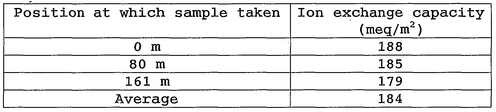
Comparative Example 2
An impregnation vapor phase graft polymerization reaction was carried out as in Example 2 using the same polyethylene fiber nonwoven fabric as that used in Example 2. Specifically, with the oxygen concentration in the irradiating chamber held at 250 ppm, the nonwoven fabric was irradiated with a 150 kGy electron beam.
A purified chloromethylstyrene (CMS-AM made by Seimi Chemical Co. , Ltd.) / toluene (weight ratio 80 / 20) solution was aerated with nitrogenfor30minutes, andwasthenintroducedintotheimpregnator. With the oxygen concentration in the impregnator held in the range of more than 5 ppm and less than 14 ppm, and the oxygen concentration in the reactor held in the range of more than 9 ppm and less than 37 ppm, the irradiated nonwoven fabric was conveyed into the impregnator at a rate of 0.6 m/min and impregnatedwith the solution, and was then conveyed into the reactor and subjected to graft polymerizationfor 40minutes at 60° C. Samples of sizeproductwidth x 300 mm were cut out at three points at 80 m intervals in the length direction of the grafted nonwoven fabric thus manufactured, and the samples were treated for 3 hours at 60° C in toluene so as to removehomopolymertherefrom. Thenonwovenfabricsampleswerethen washed with acetone, and then dried for 2 hours at 600C, whereby chloromethylstyrene-graftednonwovenfabric sampleswereobtained. The graft rate as determined from the change in the weight of each of the grafted nonwoven fabric samples obtained is shown in Table 3. The mean graft rate was 45.6%. Table 3

As in Example 2, each of the chloromethylstyrene-grafted nonwoven fabric samples obtained was immersed in a mixed liquid of isopropanol / 30% trimethylamine aqueous solution / pure water in a volume ratio of 30 / 30 / 40, and reaction to form a quaternary
ammoniumsaltwascarriedoutfor6hoursat 60° C. Eachofthenonwoven fabric samples was then taken out, washed three times with pure water at 400C, and then dried for 1 hour at 500C, whereby anion exchange type nonwoven fabric samples D were obtained. The ion exchange capacity of each of the nonwoven fabric samples D obtained is shown in Table 4. The mean ion exchange capacity was 176 meq/m2.
Table 4

Example 3 The interior of a glove box as shown in FIG. 4 was put under a nitrogen atmosphere, the oxygen concentration was continuously measuredusing a galvanic cell type oxygen concentrationmeter (made by Iijima Electronics Corporation, model number MC7G-L) as oxygen concentration measuring means, and with the oxygen concentration held in the range of more than 5 ppm and less than 30 ppm, 3.94 g (200 mm x 300 mm) of a polyethylene fiber nonwoven fabric (made by DuPont-Asahi Flash Spun Products Co. , Ltd. , trade name Tyvek, mean fiber diameter 0.5 to 10 μm, weight 65 g/m2, thickness 0.17 mm) was put into a polyethylene bag. The polyethylene bag with the nonwoven fabric therein was then taken out from the glove box, and was irradiated with a 150 kGy electron beam. A solution of lithium p-styrenesulfonate (made by Tosoh Corporation, trade name LiSS) in ethanol (weight ratio: 1/19) was aerated with nitrogen gas under an oxygen concentration of 10 ppm in the glove box for 30 minutes. The irradiated nonwoven fabric obtained as described above was
immersed in the aerated solution, then liquid was wiped off from the nonwoven fabric to make the total weight 7.80 g, and then the nonwoven fabric was put into a glass vessel under an oxygen concentration in the range of more than 5 ppm and less than 10 ppm in the glove box, the glass vessel was sealed, and graft polymerization was carried out for 3 hours at 600C. After that, the grafted nonwoven fabric was taken out, removal of homopolymer was carried out by washing with pure water at 600C, and then the water was wiped off, and drying was carried out for 1 hour at 50° C, whereby4.22 gofalithiumstyrenesulfonate-graftednonwovenfabric was obtained. The graft rate as determined from the weight change was 7.1%.
The grafted nonwoven fabric obtained was washed twice with 0.5 mol/L hydrochloric acid (500 ml), and was then washed twice with pure water (500 ml) at 600C, and then the water was wiped off, and drying was carried out for 1 hour at 500C, whereby a 4.19 g cation exchange type nonwoven fabric E was obtained. The nonwoven fabric E obtained had an ion exchange capacity of 10.1 meq/m2. Comparative Example 3 3.89 g (200 mm x 300 mm) of a polyethylene fiber nonwoven fabric (made by DuPont-Asahi Flash Spun Products Co., Ltd., trade nameTyvek, meanfiberdiameter0.5 to 10 μm, weight 65 g/m2, thickness 0.17 mm) was introduced into a polyethylene bag under a nitrogen atmosphere with an oxygen concentration in the range of more than 10 ppm and less than 25 ppm in a glove box like that used in Example 1, and the polyethylene bag with the nonwoven fabric therein was irradiated with a 150 kGy electron beam. The irradiated nonwoven fabricwas then immersedin a solution of lithiump-styrenesulfonate
in βthanol (weight ratio: 1/19) that had been aerated with nitrogen gas for 30 minutes, then liquid was wiped off to make the total weight 7.80 g, and then the nonwoven fabric was put into a glass vessel under an oxygen concentration in the range of more than 100 ppm and less than 110 ppm in the same glove box used in Example 1, the glass vesselwas sealed, and graft polymerization was carried out for 3 hours at 60° C. The grafted nonwoven fabric was then taken out, removal of homopolymer was carried out by washing with pure water at 6O0C, and then the water was wiped off, and drying was carried out for 1 hour at 500C, whereby 4.16 g of a lithium styrenesulfonate-grafted nonwoven fabric was obtained. The graft rate as determined from the weight change was 6.9%.
The grafted nonwoven fabric obtained was washed twice with 0.5 mol/L hydrochloric acid (500 ml), and was then washed twice with pure water (500 ml) at 600C, and then the water was wiped off, and drying was carried out for 1 hour at 500C, whereby a 4.13 g cation exchange type nonwoven fabric F was obtained. The nonwoven fabric F obtained had an ion exchange capacity of 9.8 meq/m2. Example 4 The sulfonatedfilmAproducedinExample 1, andthe sulfonated film B produced in Comparative Example 1 were each subjected to measurement of the elemental distribution on the surface thereof using XPS.
Specifically, the surfaceofeachfilmwaswashedwithacetone, andwas thenirradiatedwiththeKaline ofAl (1,486.6 eV) as incident X rays in an elliptical shape approximately of major diameter 200 μmandwidth20 to 30 μm. Photoelectrons thus generatedweremeasured with a wide scan, and the elemental content in atom % in a 10 nm
depth range from the surface was determined. As a result, it was found that the abundance of S for sulfonated filmA was 1 to 2 atom %. On the other hand, aresponse due to S was not detected for sulfonated film B. Example 5
Sulfonated films A and B obtained in Example 1 and Comparative Example 1 and Nafion (Trademark) Nl15 made by DuPont were subjected to measurement of the voltage under a constant current using an ion conductivity measuring apparatus as shown in FIG. 5, whereby the ion conductivity was measured. The results are shown in FIG. 6 as a graph in which the horizontal axis shows the current, and the vertical axis shows the voltage required under the constant current, which indicates the ion conductivity. From these results, it can be seen that the ion conductivity is better if the oxygen concentration during the reaction is lower. Example 6
Eight 4 mm x 25 mm strips were cut out from each of the anion exchange type nonwoven fabrics C and D obtained in Example 2 and Comparative Example 2, and the cation exchange type nonwoven fabrics E and F obtained in Example 3 and Comparative Example 3. Next, the strips were immersed in pure water and thus washed, and then the water was wiped off, and drying was carried out for 2 hours at 50° C in ahot air drier. Using awater absorptionratemeasurement method as illustrated in FIG. 7, pure water was put into a channel of depth 1 mm, each of the samples taken out from the drier was immediately stood up such that the long sides thereof were vertical and the lower end thereof was placed in the channel, and then the change over time in the height reached by the pure water was measured.
Note that the room temperature was 25° C, and the relative humidity was 55%. The mean values of the results are shown in Table 5. Note that there were no samples at all of the aerobic treatment nonwoven fabric D for which the pure water was absorbed 10 mm or more. From the above, it was found that by controlling the oxygen concentration to be low during the electron beam irradiation, an ion exchange type nonwoven fabric having a high pure water absorption rate can be obtained.
Table 5: Time taken for pure water to be absorbed (s)

Example 7
FIG.2 isaflowchartofanoxygenconcentrationcontrolmethod, and FIG. 3 is a conceptual drawing of an example of application of this'method to a continuous conveyance type grafting reaction apparatus. Using this apparatus, test operation was carried out with an oxygen concentration set value of 200 ppm on the irradiating devicesideand50ppmonthereactorside. Commencementofoperation was not possible if either of these set values was exceeded, trial operation was commenced once the oxygen concentration was below the set values, and if the oxygen concentration rose, then a warning was issued by means of a buzzer and a Patlite (registered trademark) coming on, and a warning message was displayed on a control console touch panel. In this case, the irradiation was stopped, and then conveyance was stopped.
Claims
1. An organic polymeric material comprising a chemically modified organic polymeric material substrate, wherein a response due to the chemical modification is detected byX-ray photoelectron spectroscopy (XPS) for a surface layer of the substrate.
2. An organic polymeric material according to claim 1, wherein a region of from 1 ppm to 100 nm in a depth direction of a surface layer of the substrate is chemically modified.
3. The organic polymeric material according to claim 1 or 2, wherein the substrate comprises a polyolefin and/or a halogenated polyolefin.
4. The organic polymeric material according to any of claims 1 to 3, whereintheorganicpolymericmaterial is afilm-shaped organic polymeric material comprising a chemically modified film-shaped organic polymeric material substrate.
5. The film-shaped organic polymeric material comprising a chemically modified film-shaped organic polymeric material substrate according to claim 4, wherein a region of from 0.02 % to 0.5% of the film thickness in a depth direction of a surface layer of the substrate is chemically modified.
6. The organic polymeric material according to claim 4 or 5, wherein the surface layer comprises layers on both surfaces.
7. The organic polymeric material according to any of claims 4 through 6, wherein the film-shaped substrate comprises a polyolefin and/or a halogenated polyolefin.
8. An organic polymeric material comprising a fiber or an assembly of fibers obtained by chemically modifying an organic polymericmaterialsubstratehavingthe formof afiberoranassembly of fibers, wherein a response due to the chemical modification is detected by X-ray photoelectron spectroscopy (XPS) for a surface layer of the substrate.
9. The organic polymeric material according to claim 8, wherein a region of from 1 nm to 100 nm in a depth direction of a surface layer of the fibrous substrate is chemically modified.
10. The organic polymeric material comprising a fiber or an assembly of fibers obtained by chemically modifying an organic polymericmaterialsubstratehavingtheformof afiberoranassembly of fibers according to claim 8 or 9, wherein from 0.02 % to 0.5% of the fiber diameter in a depth direction of a surface layer of the fibrous substrate is chemically modified.
11. The organic polymeric material according to any of claims 8 to 10, wherein the substrate comprises a polyolefin and/or a halogenated polyolefin.
12. The organic polymeric material according to any of claims 1 through 11, wherein in the chemically modified organic polymeric material, the chemical modification includes a radical-induced chemical reaction.
13. The organic polymeric material according to claim 12, wherein means for generating the radicals is irradiation with ionizing radiation.
14. The organic polymeric material according to any of claims 12 or 13, wherein the radical-induced chemical reaction is graft polymerization.
15. The organic polymeric material according to claim 14, wherein grafted side chains introduced onto the substrate through the graft polymerization are further chemically modified.
16. The organic polymeric material according to any of claims 1 through 15, wherein in the chemically modified organic polymeric material, the chemical modification comprises introduction of ion exchange groups.
17. The organic polymeric material according to any of claims 1 through 15, wherein in the chemically modified organic polymeric material, the chemical modification comprises introduction of ligands.
18. An electrolyte film comprising the organic polymeric material according to any of claims 1 through 16 obtained by introducing ion exchange groups onto the organic polymericmaterial substrate, wherein the ion exchange groups are introduced through reaction including a radical-induced chemical reaction.
19. An electrolyte film comprising an organic polymeric material substrate having ion exchange groups introduced thereon, wherein aresponse due to the introduction of the ion exchange groups is detected byX-ray photoelectron spectroscopy (XPS) for a surface layer of the substrate.
20. The electrolyte film according to claim 19, wherein the ion exchange groups are introduced in a region of from 1 nm to 10 nm in a depth direction of a surface layer of the substrate.
21. An electrolyte film comprising an organic polymeric material substrate having ion exchange groups introduced thereon according to claim 19 or 20, wherein the ion exchange groups are introduced in a region of from 0.003 % to 0.05% of the film thickness in a depth direction of a surface layer of the substrate.
22. The electrolyte film according to any of claims 19 through 21, wherein the surface layer comprises layers on both surfaces.
23. The electrolyte film according to any of claims 19 through 22, wherein the substrate comprises a polyolefin and/or a halogenated polyolefin.
24. A battery separator for secondary cell comprising the organic polymeric material according to any of claims 1 through 16 obtained by introducing ion exchange groups onto the organic polymeric material substrate, wherein the ion exchange groups are introduced through reaction including a radical-induced chemical reaction.
25. A battery separator for secondary cell comprising an organic polymeric material substrate having ion exchange groups introduced thereon, wherein a response due to the introduction of the ion exchange groups is detected by X-ray photoelectron spectroscopy (XPS) for a surface layer of the substrate.
26. The battery separator for secondary cell according to claim 25, wherein the ion exchange groups are introduced in a region of from 1 nm to 50 nm in a depth direction of a surface layer of the substrate.
27. A battery separator for secondary cell according to claim 25, wherein the ion exchange groups are introduced in a region of from 0.003 % to 0.25% of the film thickness in a depth direction of a surface layer of the substrate.
28. The battery separator for secondary cell according to any of claims 25 through 27, wherein the surface layer comprises layers on both surfaces.
29. The battery separator for secondary cell according to any of claims 25 through 28, wherein the substrate comprises a polyolefin and/or a halogenated polyolefin.
30. Amethod ofmanufacturing an organicpolymericmaterial by chemically modifying an organic polymeric material substrate, which comprises putting the substrate into container that can be isolated from the outside environment and in which the oxygen concentration can be held lower than that outside, generating radicals on the substrate in part of the container, and then moving the substrate into another part of the container, and chemically modifying the substrate through a radical-induced reaction, and wherein the oxygen concentration of the atmosphere in which the chemical modification is carried out is in a range of from 1 ppm to 100 ppm.
31. Amethod ofmanufacturing an organicpolymericmaterial by chemically modifying an organic polymeric material substrate, wherein the method comprises putting the substrate into a container that can be isolated from the outside environment and in which the oxygen concentration can beheld lower than that outside, generating radicals on the substrate in part of the container, and then moving the substrate into another part of the container, and chemically modifying the substrate through a radical-induced reaction, and wherein the oxygen concentration of the atmosphere in which the radicals are generated is in a range of from 1 ppm to 200 ppm.
32. Amethodofmanufacturingan organicpolymericmaterial by chemically modifying an organic polymeric material substrate, wherein the method comprises putting the substrate into a container that can be isolated from the outside environment and in which the oxygen concentration can beheld lower than that outside, generating radicals on the substrate in part of the container, and then moving the substrate into another part of the container, and chemically modifying the substrate through a radical-induced reaction, and wherein the oxygen concentration of the atmosphere in which the chemical modification is carried out is in a range of from 1 ppm to 100 ppm, and the oxygen concentration of the atmosphere in which the radicals are generated is in a range of from 1 ppm to 200 ppm.
33. The method of manufacturing an organic polymeric material according to any of claims 30 through 32, wherein the container is a container partitioned into a portion in which the radicals are generated on the substrate and a portion in which the chemical modification is carried out.
34. The method of manufacturing an organic polymeric material according to any of claims 30 through 32, wherein the container comprises a container in which the radicals are generated on the substrate and a separate container in which the chemical modification is carriedout, and themethodfurther comprises moving the substrate from the container inwhich the radicals are generated to the container in which the chemical modification is carried out viaaconnectingsectionthatisisolatedfromtheoutsideenvironment and throughwhich the substrate can bemovedwhile holding the oxygen concentration of the atmosphere therein in a range of from 1 ppm to 100 ppm.
35. Amethodofmanufacturing an organic polymericmaterial by chemically modifying an organic polymeric material substrate, wherein the method comprises putting the substrate into a container that can be isolated from the outside environment and in which the oxygen concentration can be held lower than that outside, and generating radicals on the substrate while bringing the substrate and a reactant for the chemical modification into contact with one anotherinpartofthecontainer, andwhereintheoxygenconcentration of the atmosphere in which the chemical modification is carried out is in a range of from 1 ppm to 100 ppm.
36. The method of manufacturing an organic polymeric material according to any of claims 30 through 35, wherein means for generating the radicals is irradiationwith ionizing radiation.
37. The method of manufacturing an organic polymeric material according to any of claims 30 through 36, wherein the chemical modification includes graft polymerization.
38. The method of manufacturing an organic polymeric material according to any of claims 30 through 37, wherein the substrate comprises a polyolefin and/or a halogenated polyolefin.
39. The method of manufacturing an organic polymeric material according to any of claims 30 through 38, wherein the substrate is a sheet-shaped material of a fiber aggregate or a film, and at least one selected from a step of supplying the substrate intoaspaceinwhichthereactionis carriedout, astepof generating the radicals on the substrate, a step of carrying out the chemical modification on the substrate, and a step of conveying a product out is carried out continuously.
40. The method of manufacturing an organic polymeric material according to any of claims 30 through 39, wherein the oxygen concentration in the space in which the reaction is carried out is held lower than that outside by supplying an inert gas having an oxygen concentration in a range of from 1 ppb to 100 ppm into the space in which the reaction is carried out so as to replace gas in the space in which the reaction is carried out.
41. The method of manufacturing an organic polymeric material according to any of claims 30 through 40, wherein the oxygen concentration in the space in which the reaction is carried out is held lower than that outside by supplying an inert gas having an oxygen concentration in a range of from 0.1 ppm to 100 ppm into the space in which the reaction is carried out, exhausting gas from the space in which the reaction is carried out and subjecting the gas to deoxygenation treatment, and then returning the gas into the space in which the reaction is carried out, thus carrying out circulation and replacement of the gas in the space in which the reaction is carried out. ,
42. The method of manufacturing an organic polymeric materialaccordingtoclaim40or41, whereintheinert gas isnitrogen gas of purity not less than 99.99%.
43. A method of inspecting a film-shaped organic polymeric material obtained by chemically modifying an organic polymeric material substrate, the method comprising measuring by X-ray photoelectron spectroscopy (XPS) that a region of from 1 nm to 100 nm in a depth direction of a surface layer of the manufactured film-shaped organic polymeric material is chemically modified.
44. An organic polymeric material chemical modification apparatus for manufacturing a film-shaped organic polymeric material by chemically modifying an organic polymeric material substrate, the apparatus comprising: an ionizing radiation irradiating section that is disposed in a first container that isolates the substrate from the outside environment and in which the oxygen concentration can be held lower than that outside, and is for generating radicals on the organic polymeric material substrate; a chemical modification section that is disposed in a second container that isolates the substrate from the outside environment and in which the oxygen concentration can be held lower than that outside, and is for carrying out chemical modification through a reaction induced by the radicals; and a connecting section that is disposed in a third container that isolates the substrate from the outside environment and in which the oxygen concentration can be held lower than that outside, and connects the container in which the ionizing radiation irradiatingsectionisdisposedtothecontainerinwhichthechemical modification section is disposed, enabling the substrate to bemoved therebetween, wherein one of the first container in which the ionizing radiation irradiating section is disposed, the second container in which the chemical modification section is disposed, and the third container in which the connecting section is disposed is provided with at least one inert gas supply port for supplying an inert gas into the container, and at least one exhaust port for exhausting gas from the container, and wherein the apparatus further comprises amechanism to hold the oxygen concentration of the gas in the first container inwhich the ionizing radiation irradiating section is disposed in a range of from 0.1 ppm to 200 ppm, and/or the oxygen concentration of the gas in the second container in which the chemical modification section is disposed is held in a range of from 0.1 ppm to 100 ppm.
45. An organic polymeric material chemical modification apparatus for manufacturing a film-shaped organic polymeric material by chemically modifying an organic polymeric material substrate, the apparatus comprising: a container that isolates the substrate from the outside environment and in which the oxygen concentration can be held lower than that outside; an ionizing radiation irradiating section that is disposed in the container, and is for generating radicals on the organic polymeric material substrate; a chemical modification section that is disposed in the container, and is for chemically modifying the substrate through a reaction induced by the radicals; and a conveyance section that is disposed in the container, and is for conveying the substrate from the ionizing radiation irradiating section into the chemicalmodification section, wherein the container is provided with an inert gas supply port for supplying an inert gas into the container, and an exhaust port for exhausting gas from the container, and wherein the apparatus further comprises amechanism to holdthe oxygen concentration of the gas in the container in a range of from 0.1 ppm to 100 ppm.
46. The organic polymeric material chemical modification apparatus according to claim 44 or 45, further comprising an oxygen concentration meter that continuously monitors the oxygen concentration of the gas in the ionizing radiation irradiating section and/or the chemical modification section, and further comprising a warning device for issuing a warning if the oxygen concentration deviates from a prescribed concentration range.
47. The organic polymeric material chemical modification apparatus according to any of claims 44 through 46, comprising an oxygen concentration meter that continuously monitors the oxygen concentration of the gas in the ionizing radiation irradiating section and/or the chemical modification section, and further comprising a shutdown device for stopping the irradiation with the ionizing radiation and/or stopping the chemical modification reaction if the oxygen concentration deviates from a prescribed concentration range.
48. The organic polymeric material chemical modification apparatus according to any of claims 44 through 47, comprising an oxygen concentration meter that monitors the oxygen concentration of the gas in the ionizing radiation irradiating section and/or the chemicalmodification section, and further comprising a control device for controlling commencement of operation of the apparatus to be operational when the oxygen concentration of the gas in each of the ionizing radiation irradiating section and the chemical modification section is within a prescribed concentration range.
49. A computer-readable apparatus operation program for the organic polymeric material chemical modification apparatus according to any of claims 44 through 48, for implementing a step of making the oxygen concentration of the gas in each of the ionizing radiation irradiating section, the chemical modification section and the connecting section be within a prescribed concentration range by replacing the gas in each of the ionizing radiation irradiating section, the chemical modification section and the connectingsectionwithaninertgas inwhichtheoxygenconcentration is within a prescribed concentration range, a step of moving a substrate that has been conveyed in from a substrate supply section into the ionizing radiation irradiating section, and irradiating the substrate with a prescribed amount of ionizing radiation by adjusting an irradiation source and the irradiation time, thus generating radicals on the substrate, a step ofmoving the substrate on which the radicals have been generated into the chemical modification section, bringing the substrate into contact with a prescribed reactant containing a chemical species required in chemical modification induced by the radicals, and carrying out the chemical modification at a prescribed reaction temperature for a prescribed reaction time, thus producing a chemically modified product, and a step of conveying the chemically modified product out using a product conveying section.
Priority Applications (1)
| Application Number | Priority Date | Filing Date | Title |
|---|---|---|---|
| JP2007547846A JP2008525566A (en) | 2004-12-28 | 2005-12-28 | Chemically modified organic polymer material, method for producing the same, and apparatus |
Applications Claiming Priority (2)
| Application Number | Priority Date | Filing Date | Title |
|---|---|---|---|
| JP2004379465 | 2004-12-28 | ||
| JP2004-379465 | 2004-12-28 |
Publications (2)
| Publication Number | Publication Date |
|---|---|
| WO2006070945A2 true WO2006070945A2 (en) | 2006-07-06 |
| WO2006070945A3 WO2006070945A3 (en) | 2007-02-15 |
Family
ID=36263809
Family Applications (1)
| Application Number | Title | Priority Date | Filing Date |
|---|---|---|---|
| PCT/JP2005/024284 Ceased WO2006070945A2 (en) | 2004-12-28 | 2005-12-28 | Chemically modified organic polymeric material, and method and apparatus for manufacturing the same |
Country Status (2)
| Country | Link |
|---|---|
| JP (1) | JP2008525566A (en) |
| WO (1) | WO2006070945A2 (en) |
Cited By (2)
| Publication number | Priority date | Publication date | Assignee | Title |
|---|---|---|---|---|
| EP2214226A4 (en) * | 2007-09-13 | 2013-01-02 | Nitto Denko Corp | Battery separator and nonaqueous lithium ion secondary battery having the same |
| CN118159836A (en) * | 2021-10-24 | 2024-06-07 | 诺威量测设备公司 | Characterization and measurement using XPS in a small cell in multiple measurement cases |
Families Citing this family (5)
| Publication number | Priority date | Publication date | Assignee | Title |
|---|---|---|---|---|
| JP5578557B2 (en) * | 2010-07-30 | 2014-08-27 | 独立行政法人日本原子力研究開発機構 | Method for producing metal ion collector |
| JP6485043B2 (en) * | 2013-09-27 | 2019-03-20 | 東レ株式会社 | Heat resistant resin film and method for manufacturing the same, heating furnace, and method for manufacturing image display device |
| JP7019576B2 (en) * | 2016-08-10 | 2022-02-15 | Agcエンジニアリング株式会社 | Method for processing base sheet and method for manufacturing modified base sheet |
| JP6983575B2 (en) * | 2017-08-22 | 2021-12-17 | Agcエンジニアリング株式会社 | Method for manufacturing polymer base material with graft chain |
| JP6887913B2 (en) * | 2017-08-22 | 2021-06-16 | Agcエンジニアリング株式会社 | Method for manufacturing polymer base material with graft chain |
Family Cites Families (2)
| Publication number | Priority date | Publication date | Assignee | Title |
|---|---|---|---|---|
| AU5125700A (en) * | 1999-05-04 | 2000-11-17 | Moltech Corporation | Electroactive sulfur containing, conductive, highly branched polymeric materialsfor use in electrochemical cells |
| JP3601581B2 (en) * | 1999-06-11 | 2004-12-15 | 東洋紡績株式会社 | Carbon electrode material for vanadium redox flow battery |
-
2005
- 2005-12-28 JP JP2007547846A patent/JP2008525566A/en not_active Withdrawn
- 2005-12-28 WO PCT/JP2005/024284 patent/WO2006070945A2/en not_active Ceased
Cited By (2)
| Publication number | Priority date | Publication date | Assignee | Title |
|---|---|---|---|---|
| EP2214226A4 (en) * | 2007-09-13 | 2013-01-02 | Nitto Denko Corp | Battery separator and nonaqueous lithium ion secondary battery having the same |
| CN118159836A (en) * | 2021-10-24 | 2024-06-07 | 诺威量测设备公司 | Characterization and measurement using XPS in a small cell in multiple measurement cases |
Also Published As
| Publication number | Publication date |
|---|---|
| JP2008525566A (en) | 2008-07-17 |
| WO2006070945A3 (en) | 2007-02-15 |
Similar Documents
| Publication | Publication Date | Title |
|---|---|---|
| KR100999048B1 (en) | Method for preparing anion exchange composite membrane containing styrene-vinylbenzyl copolymer | |
| CA1333236C (en) | Hydrophilic microporous membrane and process for preparing same | |
| JP5196234B2 (en) | Anion exchange membrane and method for producing the same | |
| EP0424873A2 (en) | Method for modifying the surface of a polymer article | |
| Lehtinen et al. | Effect of crosslinking on the physicochemical properties of proton conducting PVDF-g-PSSA membranes | |
| WO2006070945A2 (en) | Chemically modified organic polymeric material, and method and apparatus for manufacturing the same | |
| JP5196236B2 (en) | Cation exchange membrane and method for producing the same | |
| CN112915793A (en) | Single-sheet bipolar membrane roll with screen cloth support and manufacturing method thereof | |
| US11517894B2 (en) | Processing method of base material sheet, manufacturing method of modified base material sheet, base material with grafted polymer chain, and ion exchange membrane | |
| JP3741871B2 (en) | Radiation graft polymerization method | |
| Omichi et al. | Accurate measurement of the localized degree of grafting using thermogravimetric analysis | |
| Ingram et al. | Radiation grafting of vinyl monomers to wool. III. Location of the grafted polymer | |
| CN101128523B (en) | Functional membrane and process for production thereof, and electrolyte membrane for fuel cell and process for production thereof | |
| Kabanov | Preparation of polymer membranes for fuel cells by radiation graft polymerization | |
| JP2001048923A (en) | Functional polytetrafluoroethylene resin and method for producing the same | |
| CN103998926B (en) | Protein adsorption material | |
| Kuznetsov et al. | Production and investigation of nuclear track membranes at JINR | |
| US8329766B2 (en) | Functional membrane and production method thereof, and electrolyte membrane for use in fuel cell and production method thereof | |
| Yamaki et al. | Proton exchange membranes for fuel cell applications prepared by ion track technology | |
| Yamaki et al. | Nano-structure controlled polymer electrolyte membranes for fuel cell applications prepared by ion beam irradiation | |
| JP2006241618A (en) | Continuous radiation graft polymerization of organic polymer composites | |
| Kang et al. | Radiolytic preparation of poly (styrene sulfonic acid)–grafted poly (tetrafluoroethylene-co-perfluorovinyl vinyl ether) membranes with highly cross-linked networks | |
| JP2005248362A (en) | Graft polymerization equipment | |
| JP3796220B2 (en) | Graft polymerization method for polymer substrate | |
| Sawada et al. | Creation of nanostructure-controlled functional membranes using high-energy ion beams |
Legal Events
| Date | Code | Title | Description |
|---|---|---|---|
| 121 | Ep: the epo has been informed by wipo that ep was designated in this application | ||
| WWE | Wipo information: entry into national phase |
Ref document number: 2007547846 Country of ref document: JP |
|
| NENP | Non-entry into the national phase |
Ref country code: DE |
|
| 122 | Ep: pct application non-entry in european phase |
Ref document number: 05824467 Country of ref document: EP Kind code of ref document: A2 |
|
| WWW | Wipo information: withdrawn in national office |
Ref document number: 5824467 Country of ref document: EP |