NOISE. REDUCTION IN DIGITIZER SYSTEM
FIELD AND BACKGROUND OF THE INVENTION The present invention relates to noise reduction in a system comprising a digitizer and, more particularly, but not exclusively to noise reduction in a system comprising a digitizer associated with a display screen. US patent 6,690,1-56 "Physical Object Location Apparatus and Method and a Platform using: the same" assigned to N-trig Ltd, and US patent application number 10/649,708 "Transparent Digitizer" also assigned to N-trig Ltd, describe a positioning device capable of detecting multiple physical objects, preferably styluses, located on a flat screen display. One of the preferred embodiments in both patents describes a system built .of ■transparent foils containing a matrix of vertical and horizontal conductors. In one ^embodiment the stylus includes a passive resonance circuit, which is triggered by aή:;excitatiori coil that surrounds the foils. The stylus is excited at a predeterm ed.range of frequencies depending on the capacitance and inductance of the resonant circuit. Other, embodiments may include a different kind of EM stylus. The exact position of the stylus is determined by processing the signals that are sensed by the matrix of horizontal and vertical conductors. Existing digitizer systems use several noise removal methods to improve the detection precision. For example the received signal is processed through a band pass filter leaving a window of frequencies including the stylus frequency. The filtered signal may then be passed through a Fourier transform selecting the single frequency
operation. The application may utilize a passive EM stylus. External excitation coils that surround the sensor are utilized to energize the stylus. However, other versions may include an active stylus, batter operated or wire connected, which does not require external excitation ^circuitry. In one application the electromagnetic object responding to the excitation is a stylus. However, other embodiments may include other physical objects comprising a resonant circuit
" o active oscillators, such as gaming pieces. Applications describing gaming tokens comprising resonant circuits are described in US Patent No. 6,690,156 ("physical object location apparatus and method and a platform using the same"). In the preferred application, the digitizer can detect simultaneous and separate inputs from an electromagnetic stylus and a user finger. Hence, it is capable of functioning as;; a touch detector as well as detecting a stylus. However, other embodiments may. include a digitizer capable of detecting only an electromagnetic stylus.
a display. The transparent digitizer is described in US patent 6,690,156 and detailed in US patent application 10/649,708. The various components and functionality manner of the transparent digitizer are as follows., .
.

Detection of stylus The preferred, digitizer utilizes a passive electromagnetic (EM) stylus. The stylus comprises two main sections; the first section is an energy pick-up circuit and the second section is an active oscillator which is coupled to the stylus tip. An external excitation .coil that surrounds the sensor supply energy to the energy pick up circuit. The received energy is transferred to the active oscillator through a rectifying component such as, a diode bridge. The exact position of the stylus is determined by the detector, Which processes the signals sensed by the sensor. In the preferred embodiment only the electric wave of the electromagnetic signal generated by the stylus, is utilized;: However, other embodiments may utilize the magnetic portion in addition or instead of the electric wave. For further information please refer to US patent application , 10/649,708 assigned to N-trig, and US provisional patent application "Electromagnetic Stylus for a Digitizer System" filed December 2004, also assigned to N trig, the contents of both applications are hereby incorporated by reference. In the, preferred digitizer, the basic operation cycle consists of windowing, FFT/DFT, peak
1 detection, interpolation, filtering and smoothing. For further information please refer to US patent application 10/649,708, sub-title: "Algorithms". Noise Soύjrces There a be a - ariety of noise sources in the stylus frequency range. The most corrnriott signals interfering with the stylus signals are signals that originate from conductive objects; such as a user finger, touching the screen. Fig 1 is an electrical equivalent of a user finger touching one of the digitizer's antennas. When the user touches an antenna, 11 a capacitance 12 is formed between the finger and the sensor conductors; The riόise situation is best explained with respect to finger induced noise signals. A

2. When the user's body is subjected to electromagnetic interferences from the environment, it, arid any associated finger, oscillates in reference to the system; as a result a leakage current is induced from the user's finger to the conductive antennas. In both cases, the digitizer senses a leakage current originating from the user touching the sensor. When the leakage current induces a signal that is at the same frequency of the stylus, the leakage current can be mistaken for a stylus signal. A second possible source of noise is the electronic components within the system, which; radiate af many frequencies. These components may induce noise signals at the- .stylus frequency; thus interfering with stylus detection. Electronic devices placed mproxirnity to the system, such as cellular phones, may also radiate in frequencies that interfere with the stylus detection. Fig 2 is an example of a noise and stylus affecting the sensor at the same time. In this case the noise source is the user's finger touching the screen. The sensor 20 comprises a matrix of conductive lines. When stylus tip 21 is present at the surface of the sensor it affects the antennas in its proximity. One or more antennas in proximity to the stylus may suffer noise signals induced by a finger 22 touching the sensor. For example, antenna/23 exhibits signals induced by both stylus 21 and finger 22.
The second rid of problem is when the stylus signal is stronger than the finger-induced signal. However, an error in the stylus detection may still occur during the interpolation step of the detection. Fig 4, to which reference is now made, describes a case when a user's finger 22 touching the screen induces a signal that causes the digitizer to miscalculate the stylus position 34. The user finger 22 induces a signal on one; of the X axis antennas 31 while the stylus 21 is located closer to a different X axis antenna 32. The signal received on the stylus antenna 32 is weaker than the signal
. '33 received on the finger antenna 31. Hence, the digitizer will miscalculate the stylus position 34. The object -of the present invention is to solve both cases and eliminate noise above and below the level of the stylus signal. There is thus a widely recognized need for, and it would be highly advantageous to have, a noise, reduction system devoid of the above limitations.
SUMMARY OF THE INVENTION According to one aspect of the present invention there is provided a method for noise reduction in a digitizer, the digitizer comprising a plurality of detecting elements for detecting an electromagnetic signal at one of a number of predetermined frequencies: the method comprising: sampling at least two of the detecting elements substantially simultaneously to obtain outputs, therefrom, and reducing the output on one of the two elements in accordance with the output on the other of the elements. Preferabjiy,rorie of the atleast.two elements is selected as a candidate carrier of a stylus signal; and the other -of the at least two elements is selected as a candidate carrier of mere; noise. . The method preferably comprises detecting at each of the elements the one predetermined frequency and anόther arbitrary frequency. The meth d preferably comprises utilizing the arbitrary frequency to estimate the amount, of ijoise at the predetermined frequency. The method. preferably further comprises: deteirn imng a ratip between signals of the one predetermined frequency and the arbitrary, frequency at the candidate carrier of mere noise,
from the ratio and; the arbitrary signal at the candidate carrier of the stylus signal determining an amount of noise at the one predetermined frequency, and reducing a; signal at the one predetermined frequency at the candidate carrier of a stylus signal by the determined amount of noise. Preferably,,- the arbitrary frequency is selected as a frequency within a preset detection range having a relatively high noise. Preferably, the digitizer is also for touch detection and the arbitrary frequency

The method may comprise verifying the presence of a stylus, beforecarrying out the reduction,. by comparing magnitudes at the arbitrary frequency and magnitudes at the predetermined frequency. In one preferred embodiment: the candidate carrier of mere noise is arbitrarily selected, noise subtraction is carried out over a group of antennas on the basis of the selection being correct, a resulting signal pattern over the group of antennas is analyzed, and the arbitrary selection is rejected if the resulting signal pattern is indicative of an incorrect selection, and a new arbitrary selection is made. The mempd may comprise using as a pattern indicative of an incorrect selection a pattern indicative of a stylus at or near the selected candidate. The methPd may coriiprise using a complex proportion to compensate for at least orie of phase and magnitude differences between respective antennas during the compensating: The method may comprise sampling a group of antennas of an array, selecting at least one antenna which is least affected by the stylus and reducing respective outputs of at least some remaining antennas in accordance with the output of the selected antenna. The method may comprise using a plurality of arbitrarily selected frequencies to calculate the reduction. The method may comprise using an average output of the plurality of arbitrarily selected frequencies to calculate the reduction. Preferably, -the detecting elements are conductive detectors of a flat array of the digitizer for -digitizing, signals of a movable object to indicate location of the object. Preferably-; the. oise . is at least in part a consequence of the presence of a finger. Preferably,, the . digitizer comprises a detection surface for carrying the detecting elements; the detecting surface further being touch sensitive. According to a second aspect of the present invention there is provided apparatus for noise , reduction- in a -digitizer, the digitizer comprising a plurality of
detecting elements for detecting an electromagnetic signal at one predetermined frequency of a- plurality of predetermined frequencies: the apparatus comprising: a sampler for sampling at least two of the detecting elements substantially simultaneously to obtain outputs therefrom, and a noise reduction unit for reducing the output on one of the two detecting elements in accordance with the output on the other of the detecting elements. Preferably, one of the
. detecting elements is selected as a candidate carrier of a stylus signal and the other of the detecting elements is selected as a candidate carrier of mere noise. The apparatus may comprise a frequency detector for detecting outputs at each of the defecting elements at the predetermined frequency and another arbitrary frequency. The apparatus may comprise a ratio; finder for deterrrύrring a ratio between outputs at the predetermined frequency and the hitrary frequency at the candidate carrier of mere noise, arid wherein the noise; reduction unit is operable with the ratio finder to: determine from the ratio and the arbitrary signal at the candidate carrier r of the ; stylus signal determining an amount of noise at the predetermined frequency, and reduce the output at the predetermined frequency at the candidate carrier of a stylus signal by the determined amount of noise. Preferably, the detecting elements are transparent conductors. Preferably,
. the arbitrary frequency is selected as a frequency within a preset detection range hav g a relatively high noise. Preferablyy the arbitraty
: frequency is selected as a frequency already used for finger detection. ; :•: The, apparatus may comprise a noise generator for deliberately generating noise at the arbifrary frequency A . Preferably: the predeterrniried frequencies are liable to change during use, the apparatus accdrdingly being, configured to change the arbitrary frequency from a frequency relatively- close tp. ;a first predetermined frequency to a second frequency relatively close
1 tp a second predeteπriined frequency.
Preferably,, the candidate carrier of mere noise is selected from a group of detection elements exhibiting more than a threshold amount of noise, as the element in the group which is furthest away from a stylus previously known location. Preferably, the candidate carrier of mere noise is selected as an element exhibiting a strongest noise signal as long as it is beyond a determined distance from a stylus previously ktipwn location. Iri an embodiment, the candidate carrier of mere noise is arbitrarily selected or otherwise chosen^, say using a selection algorithm, noise subtraction, is carried out over a group of elements on the basis of the selection being correct j a resulting signal pattern over the group of elements is analyzed, and

Preferably, the noise reduction unit is configured to use a plurality of arbitrarily selected frequencies to calculate the reduction. Preferably; the noise reduction unit is configured to use an average noise level of the plurality'of arbitrariiy selected frequencies to calculate the reduction. 5 Preferably; the elements are conductive detectors of a flat array of the digitizer for digitizing sigrials of a movable object to indicate location of the object. Preferably, the movable object is a stylus. Preferably, the stylus is an electromagnetic stylus. Preferably, the: stylus comprises an active oscillator and an energy pick up 10 circuit. Preferably, the stylus coriiprises a resonance circuit. Preferably, the detecting elements are arranged in a grid array. Preferably, the detecting elements are loop elements. Preferably, the noise is at least in part a consequence of the presence of a 15 finger. Unles&ptherwise. defined, all technical and scientific terms used herein have the same meaning as cpriimonly understood by one of ordinary skill in the art to which this invention belongs.;. The materials, methods, and examples provided herein are illustrative, onljy arid not intended to be limiting. 20 Implementation of the method and system of the present invention involves performing or
: completing certain selected tasks or steps manually, automatically, or a combination thereof Moreover, according to actual instrumentation and equipment of preferred embodiments of the method and system of the present invention, several selected steps. could be implemented by hardware or by software on any operating 25. ; system of any firmware or a combination thereof. For example, as hardware, selected steps of the. invention could be implemented as a chip or a circuit. As software, selected steps of .the invention could be implemented as a plurality of software mstractionsvbemg -executed by a computer using any suitable operating system. In any case, selected st s f the ώethod and system of the invention could be described 30 as being
'perfptrned.hy a; data processor, such as a computing platform for executing a plurality of . instructions. /•;
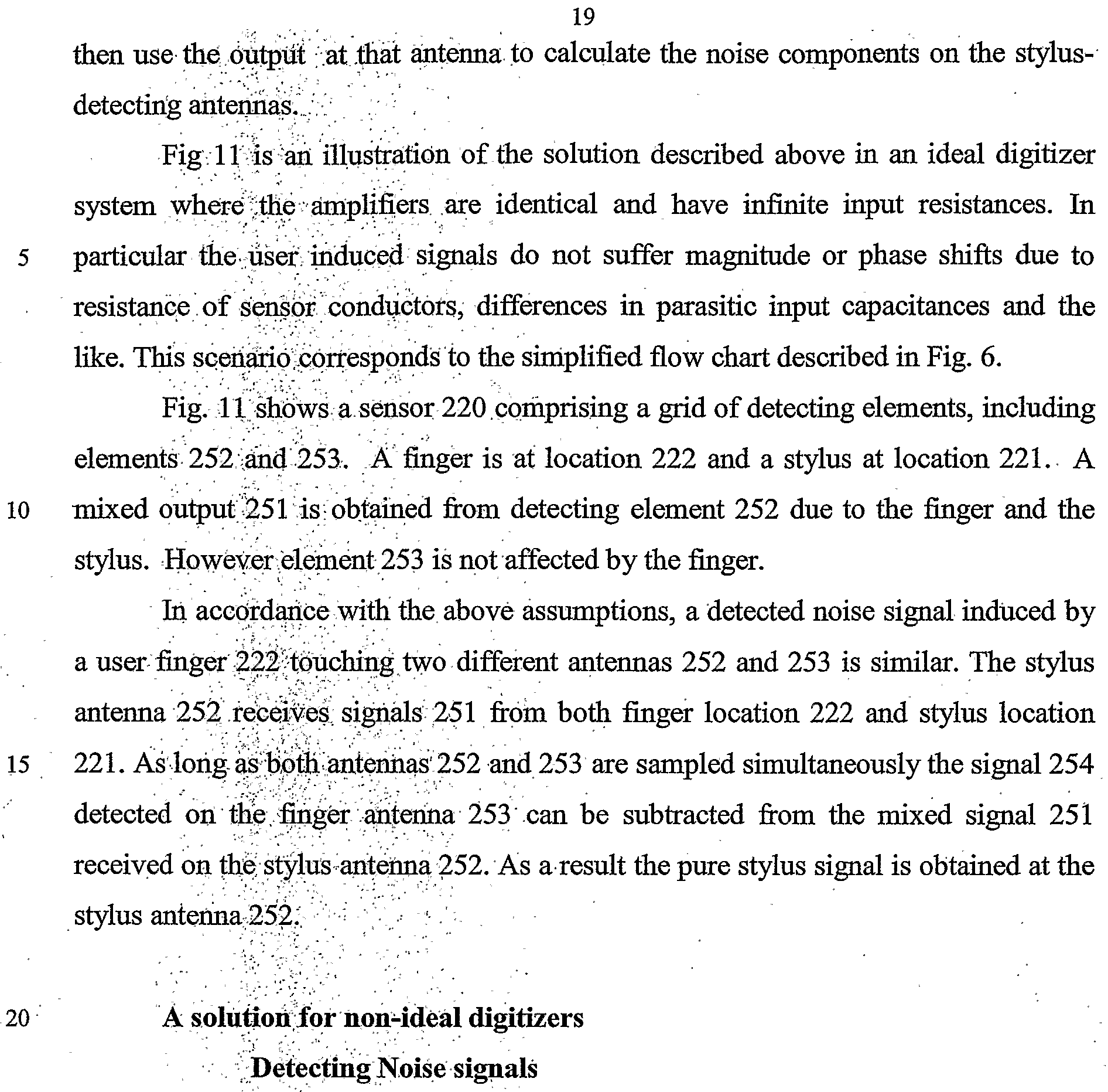
FIG. ϊϊ is a simplified diagram illustrating operation of a digitizer according to an idealized embodiment of the present invention; FIG. 12 is a simplified diagram illustrating operation of the digitizer of FIG.
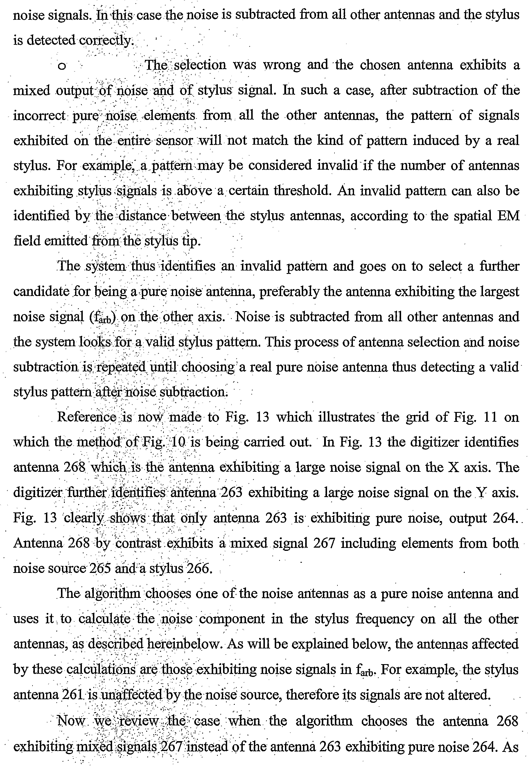
11 in a less idealized case; FIG. 13 is a simplified diagram illustrating operation of a digitizer according to a preferred embodiment of the present invention in which the method of FIG. 10 is used to identify a.carididate carrier of pure noise; FIG. 14 is, a simplified diagram illustrating the operation of FIG. 10 in an alternative outcome; FIG. 15 is a simplified diagram showing the equivalent components that contribute to noise detected by the digitizer; FIG. 16 is A simplified diagram showing how the situation shown in Fig. 15 varies for two noise sources; and FIGS. ' 7 arid ,18 are two graphs illustrating signals sampled at antennas according to preferred embodiments of the present invention.
DESCRIPTION OF HE PREFERRED EMBODIMENTS The present embodiments comprise a noise reduction system for stylus detection in a. digitizer. More particularly, the present embodiments comprise a system for noise identification and reduction at the signal frequency beirig used for detection of the stylus.1' It is rioted. that if the digitizer is combined with a touch detector, , then ..th -finger involved in touch detection is likely to be a source of noise specifically at -the stylus detection frequency. Sucϊi noise redύcfiph specifically at the detection frequency may thus improve the detection of an elecfrbmagnetic stylus in a digitizer system. The digitizer is a computer associated input device capable of tracking user interactions via the stylus or other locatable objects. In general the digitizer is associated with a display screen, on which the results of stylus, detection may. be displayed. The digitizer may further enable touch detection. The present invention does not require that the digitizer be placed directly on the display screen, "Rather, it is applicable both to transparent digitizers where the stylus is moved p er the. 'display screen and to other types of stylus, which are moved over tablets: or pa|)er/pr. whiteboards. ..
The present invention further applies to any kind of stylus or other pointer device which has a detection frequency and not merely to a passive electromagnetic stylus. The noise reduction algorithin described herein can be implemented on any digitizer system capable of tracking one or more electromagnetic styluses. The present
currently active application il8, so that the application knows where the pointer is and can incorporate the position into its current operation. Reference is riowinade to Fig. 6, which is a simplified diagram illustrating the basic principle behind noise reduction according to the present embodiments. The digitizer as shown in Fig 5 has several detecting elements which between them detect signals from the stylus, -h a world without noise the detectors having the strongest signal would be taken as the location of the stylus. If two detectors give strong
reduction, stage; 130, , an arbitrary frequency is selected which is close to the frequency beirig used by the stylus so that noise levels at the two frequencies may be
As explaine above, a preferred implementation of the present invention utilizes noise signals at an arbitrary frequency, different from the stylus frequency, in order to reduce noise signals iϋ the stylus frequency. For purposes of the present
25 disclosure the frequency used for noise signals that are not at the stylus frequency will be referred to: •••asij ,.. As /described above, the digitizer preferably finds an antenna exhibiting pure npise signals; in order to eliminate the noise signal from the stylus antenna. Orie ay;τ, ;find;aφιire noise aritenna lies in the ability to detect noise signals ' in fttb- . • •. A . : ■' . β '.;:
30. The noise
' spectrtiin is usually wider then the stylus frequency range; thus sampling a range of freiquencies around the stylus frequency is most likely to reveal noise signals at.όtfret. fe well. In this case each time the digitizer samples the antennas it scans a. range
1 of frequencies around the stylus frequency. Signals
The preferred embodiments use two different methods in order to find a pure noise antenna: The. first method, described above with respect to Fig. 9, is applicable only when the previous location of the stylus is known. Fig. 12 is a simplified diagram illusfrating a digitizer on which is carried out the method of Fig. 9, namely of finding the pure noise antenna using the stylus' previous location. Fig. 12 shows the same grid arrangement as in Fig. 11, with a finger at one location and the stylus at another location. The method of Fig! 12 relies on the fact that the stylus movements across the sensor are continuous. In addition, the antennas sampling rate is such that the previous location of the stylus is a good indication of its current whereabouts. The following steps are used to identify the pure noise antenna: 1. Detecting antenna exhibiting noise signals in f
arb - This stage can be preformed in any of the ways described hereinabove or any other methods that may occur to the skilled person. 2. Ignore any antennas that might be used for stylus detection, such as antenna 261. The algorithm chooses the antenna farthest away from the stylus' previous location, but still exhibiting a noise signal exceeding a certain threshold. In this case antenna 262 is most likely to be chosen as it has a noise source located thereon, namely a. finger. Alternatively, the algorithm may choose the antenna exhibiting the strongest noise signal as: long as it is sufficiently distanced from the stylus previous location, again as described; above. The second/method, as illustrated above in Fig. 10, does not rely on the previous location; of the stylus, thus it can be implemented even when the stylus is not present at the sensor surface or when a previous location is not known. The procedure of finding the noise antenna, using the Second method is as follows - 1. Detecting several antennas exhibiting a strong enough noise signal in fa
rb - as. described hereinabove, 2. Ohbbse one of the antennas to calculate the noise component in the stylus frequency on all the other antennas, as described elsewhere herein. The choice may be made arbitrarily or using any suitable algorithm. 3. If there is "no stylus in the region of the sensor then the selected antenna mύstexhibit a pure noise signal and after subtraction all other signals will be
very low. On the other hand, if there is a stylus detected by the sensor, there are two options: o The selection was correct and the chosen antenna exhibit pure
a result of choosing the wrong antenna the digitizer will not be able to determine the stylus position/ Referring now to Fig. 14, we describe the signals received at antenna
the followmgratip^- ;;;^ -^^^'^
threshold it means, that, he signals are most likely originating from noise in the stylus frequency rather than a stylus. In this case the signals are preferably discarded.
Proportion coefficient between a pair of antennas As explained above, when a signal is induced by a single source, the digitizer may sense thatsigial in a different magnitude or phase on different antennas. Some of the reasons for the differences i phase and magnitude are: • The distance of the signal source form the different antennas ••-• h fact that the amplifiers at the end of the antennas are not necessarily identical, they may for example have different input resistances. • The different locations of the signal source in respect to the inputs to
. . . . . . 26 The oscillating signals 280 and 281 oscillate at two different yet relatively close frequencies ft and f
2. The oscillating energy is transmitted to the antennas through the equivalent of a set of resistors and capacitors as previously described in
Fig. 16. Signals induced by first oscillator 280 are received on first antenna 273 as signal Si (ft).28.2 arid as signal S2(ft) 283 on second antenna 277. Signals induced by the second oscillator .281 are received on first antenna 273 as signal Sι(f2) 284 and as signal S2(f2) 285 on second antenna 277. The oscillating frequencies are such that the same proportion coefficient can be used for signals at both frequencies. As long as the above signals are sampled at the same time, a proportion coefficient can be used for calculating signals received on the first antenna by sampling the signals received on the second antenna:
Equation !2: 'Wή ~ C' l ϊ) Equation 3 : $ fø) C;S2 2 ) Since the/proportion coefficient is approximately the same for both of the above equations —
Equation 4: S & ) S.2 ^ ) The present invention uses Equation 4 in order to calculate the noise component on.the stylus frequency as will be elaborated bereinbelow.
Subtracting the Noise component from the stylus signal The preserit embpdittiehts may be implemented on any antenna, whether or not it exhibits a stylus signal:, It Is possible to calculate the pure noise signal on each and every antenna and subfraόtit frorn the overall signal received on said antenna. When a stylus signal : ' irideed present, the result will be a pure stylus signal. When the antenna is unaffected; by the stylus . the subtraction of the pure noise signal will indicate that ήp signals are present on the antenna. In both cases precise detection of the stylus is! acl-rieyed. A ■ The above; principle is now explained using one antenna exhibiting mixed stylus arid noise
. signals and another antenna exhibiting pure noise signals. Reference is now made , p Fig, 17, hich is. a graph showing intensity vs. frequency of the
". -
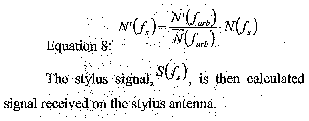
■ -.. .• 28 Once / A-' is. calculated it is subtracted from the signal received on the stylus antenna revealing the signal induced by the stylus alone
Improving1 the .proportion coefficient calculations The preferred embodiments use the ratio between detections at the pure noise antenna and detections received on other antennas at different frequencies in order to calculate the noise cPrripbrienf ori the stylus frequency as explained.
lines provides detections at frequencies - ori a stylus antenna due to finger noise alone is -
by subtracting v*' from the
It is expeόted that during the life of this patent many relevant stylus devices and digitizer/systems will be developed and the scope of the corresponding terms herein, is intended to include ail such new technologies a priori.
It is appreciated at certain features of the invention, which are, for clarity, described .fhe cbritext of separate embodiments, may also be provided in combination ih a.sϊngle embodiment. Conversely, various features of the invention, which are, for brevity, described in the context of a single embodiment, may also be pro vided. separately or ariy suitable subcombination.