WO2005013590A1 - Communication system, call connection server, terminal apparatus and communication method - Google Patents
Communication system, call connection server, terminal apparatus and communication method Download PDFInfo
- Publication number
- WO2005013590A1 WO2005013590A1 PCT/JP2003/014939 JP0314939W WO2005013590A1 WO 2005013590 A1 WO2005013590 A1 WO 2005013590A1 JP 0314939 W JP0314939 W JP 0314939W WO 2005013590 A1 WO2005013590 A1 WO 2005013590A1
- Authority
- WO
- WIPO (PCT)
- Prior art keywords
- terminal
- terminal device
- user
- identifier
- unit
- Prior art date
Links
- 238000004891 communication Methods 0.000 title claims abstract description 138
- 238000000034 method Methods 0.000 title claims description 31
- 238000001514 detection method Methods 0.000 claims description 14
- 230000005540 biological transmission Effects 0.000 claims description 6
- 238000010586 diagram Methods 0.000 description 13
- 230000006870 function Effects 0.000 description 12
- 230000000977 initiatory effect Effects 0.000 description 7
- 230000005236 sound signal Effects 0.000 description 6
- 230000008859 change Effects 0.000 description 5
- 230000008569 process Effects 0.000 description 4
- 238000005516 engineering process Methods 0.000 description 3
- 241000282693 Cercopithecidae Species 0.000 description 1
- 238000006243 chemical reaction Methods 0.000 description 1
- 230000000694 effects Effects 0.000 description 1
- 230000007246 mechanism Effects 0.000 description 1
- 238000010295 mobile communication Methods 0.000 description 1
- 230000004044 response Effects 0.000 description 1
Classifications
-
- H—ELECTRICITY
- H04—ELECTRIC COMMUNICATION TECHNIQUE
- H04M—TELEPHONIC COMMUNICATION
- H04M3/00—Automatic or semi-automatic exchanges
- H04M3/42—Systems providing special services or facilities to subscribers
-
- H—ELECTRICITY
- H04—ELECTRIC COMMUNICATION TECHNIQUE
- H04M—TELEPHONIC COMMUNICATION
- H04M3/00—Automatic or semi-automatic exchanges
- H04M3/42—Systems providing special services or facilities to subscribers
- H04M3/42229—Personal communication services, i.e. services related to one subscriber independent of his terminal and/or location
- H04M3/42263—Personal communication services, i.e. services related to one subscriber independent of his terminal and/or location where the same subscriber uses different terminals, i.e. nomadism
-
- H—ELECTRICITY
- H04—ELECTRIC COMMUNICATION TECHNIQUE
- H04L—TRANSMISSION OF DIGITAL INFORMATION, e.g. TELEGRAPHIC COMMUNICATION
- H04L12/00—Data switching networks
- H04L12/66—Arrangements for connecting between networks having differing types of switching systems, e.g. gateways
-
- H—ELECTRICITY
- H04—ELECTRIC COMMUNICATION TECHNIQUE
- H04L—TRANSMISSION OF DIGITAL INFORMATION, e.g. TELEGRAPHIC COMMUNICATION
- H04L65/00—Network arrangements, protocols or services for supporting real-time applications in data packet communication
- H04L65/1066—Session management
- H04L65/1069—Session establishment or de-establishment
-
- H—ELECTRICITY
- H04—ELECTRIC COMMUNICATION TECHNIQUE
- H04L—TRANSMISSION OF DIGITAL INFORMATION, e.g. TELEGRAPHIC COMMUNICATION
- H04L65/00—Network arrangements, protocols or services for supporting real-time applications in data packet communication
- H04L65/1066—Session management
- H04L65/1101—Session protocols
- H04L65/1104—Session initiation protocol [SIP]
-
- H—ELECTRICITY
- H04—ELECTRIC COMMUNICATION TECHNIQUE
- H04M—TELEPHONIC COMMUNICATION
- H04M7/00—Arrangements for interconnection between switching centres
- H04M7/006—Networks other than PSTN/ISDN providing telephone service, e.g. Voice over Internet Protocol (VoIP), including next generation networks with a packet-switched transport layer
-
- H—ELECTRICITY
- H04—ELECTRIC COMMUNICATION TECHNIQUE
- H04W—WIRELESS COMMUNICATION NETWORKS
- H04W40/00—Communication routing or communication path finding
- H04W40/02—Communication route or path selection, e.g. power-based or shortest path routing
- H04W40/20—Communication route or path selection, e.g. power-based or shortest path routing based on geographic position or location
Definitions
- the present invention relates to a communication system for providing a voice communication service.
- the present invention relates to a communication system, a call connection server, a terminal device, and a communication method for connecting a call in an IP telephone system to a predetermined connection destination.
- IP telephone services with the same functions as conventional subscriber telephone services (POTS) has started.
- POTS subscriber telephone services
- the network of the IP telephone service and the network of the subscribed telephone service are mutually connected. It is connected. Therefore, when the user uses both services, for example, a call for the telephone number assigned in the IP telephone service can be transferred to the telephone number assigned in the subscribed telephone service.
- IP telephone terminal having a function for using the IP telephone service at an arbitrary location on a network (IP network) where IP packets can be transferred.
- IP network IP network
- a personal computer equipped with the function can be connected to perform communication.
- the user in order to connect a call to a terminal or the like connected to an arbitrary part of the network, the user must, for example, comply with IETF RFC2543.
- the redirect mode of the SIP Session Initiation Protocol
- the information such as the IP address of the terminal device stored in the call connection server that executes the call connection on the IP network is changed in advance. There was a problem that had to be done. Also, in general, the change of the information
- the user in order to realize the above-described call transfer, the user must transfer the information of the transfer destination to a database referred to by the call connection server via a Web site or the like every time the terminal device is connected. There was a problem that had to be changed.
- the present invention has been made in view of such a problem, and has a terminal device automatically transmit information for identifying the terminal device and information indicating a position on the network, and transmit the transmitted information to the terminal device.
- a call connection server, a terminal device, and a communication method capable of connecting a call for a predetermined telephone number to the terminal device by changing information of the call connection server based on the information For that purpose. Disclosure of the invention
- a first feature of the present invention is a communication system comprising: a terminal device; and a call connection server that connects a call for a predetermined telephone number to the terminal device based on a connection destination address associated with the predetermined telephone number. If the terminal device is connected to a network capable of communicating with the call connection server, a terminal identifier for identifying the terminal device and a terminal position for specifying a position on the network to which the terminal device is connected. And a registration information transmitting unit for transmitting a terminal identifier and a terminal location address to a predetermined telephone number, a connection destination address, and a terminal identifier.
- Registration information receiving unit to be An authentication unit that authenticates the terminal device based on the identifier and the terminal identifier stored in the storage unit; and when the authentication unit authenticates the terminal device, the authentication unit associates the terminal device with the received terminal location address and the terminal identifier.
- a priority connection destination setting unit for associating a predetermined telephone number stored in the storage unit with a terminal location address as a priority connection destination prior to a connection destination address, and a terminal when a priority connection destination is set.
- a call connection unit for connecting a call to a terminal device based on the end position address.
- the call for the predetermined telephone number is connected to the terminal device based on the terminal location address transmitted by the terminal device, so that the user can use the terminal device for the call for the predetermined telephone number. Can be used to respond.
- the terminal location address transmitted by the terminal device is automatically set as a priority connection destination prior to the connection destination address, thereby avoiding a manual change of the connection destination address by the user. Can be.
- the terminal device is authenticated based on the terminal identifier transmitted from the terminal device and the terminal identifier stored in the storage unit, so that the terminal device is used without using the user ID and the password. It is possible to determine whether or not the service can be provided.
- the call connection server further includes a detecting unit for detecting that the terminal device has been disconnected from the network, and the terminal device is connected to the network by the detecting unit.
- the gist is that the priority connection destination setting unit releases the set priority connection destination when it is detected that the priority connection destination is disconnected from the network.
- the set priority connection destination is released, so that the call connection server disconnects the terminal device from the network. If there is a call, a call to a predetermined telephone number is made based on the connection destination address stored in the storage unit in advance. Can be connected.
- the storage unit further stores a user identifier for identifying a user who uses the predetermined telephone number and a password associated with the user identifier.
- the registration information transmission unit further transmits the user identifier and the password to the call connection server, the registration information reception unit further receives the user identifier and the password, and the authentication unit receives the registration.
- the gist is to authenticate the terminal device based on the terminal identifier, the user identifier, and the password.
- the terminal device is authenticated based on the user identifier and the password in addition to the terminal identifier transmitted from the terminal device, it is possible to improve security against use of an unauthorized service.
- the terminal device further includes a terminal identifier storage unit that stores a terminal identifier that can be read only by the registration information transmitting unit; The gist is to transmit the terminal identifier read from the terminal identifier storage unit to the call connection server.
- the terminal device further includes a terminal identifier storage unit that can only read the terminal identifier, and the registration information transmitting unit transmits the terminal identifier read from the terminal identifier storage unit. Identifiers can be prevented from being changed, and security against unauthorized use of services can be improved.
- the terminal device further includes a user information storage unit that stores a user identifier and a password
- the registration information transmitting unit includes the terminal identifier and the user information.
- the gist is to transmit the user identifier and password stored in the storage unit to the call connection server.
- the terminal device further includes a user information storage unit that stores the user identifier and the password, and the registration information transmitting unit stores the terminal identifier and the user information. Since the user identifier and the password stored in the unit are transmitted, it is possible to prevent the user from inputting the user identifier and the password for each connection.
- a sixth feature of the present invention is the terminal device according to the first feature of the present invention, wherein the terminal device includes a self-service base station device connectable to a network, a registration information transmitting unit, and a general radio base station or the self-service base station.
- a mobile terminal device that can be connected to a network through wireless communication with a station device, using the same protocol as that used in wireless communication between the mobile terminal device and a general wireless base station.
- the gist of the portable terminal device is that it can perform wireless communication with the self-managed base station device.
- the portable terminal device enables both the general wireless base station and the self-operating base station device to access the network using the same protocol. Can operate without considering whether to communicate with the base station.
- the mobile terminal device and the self-operating base station device further include a first communication interface for wireless communication using the above-described protocol, and a short-distance communication interface.
- the gist of the present invention is to include a second communication interface for communication, and switching means for switching between the first communication interface and the second communication interface by a user operation.
- wireless communication using the same protocol as that of a general wireless base station and short-range wireless communication such as wireless LAN can be properly used, and operations according to the communication environment can be performed.
- the self-contained base station device includes an adapter unit detachable from a computer and a communication antenna unit for wireless communication with the portable terminal device. Is the gist.
- a ninth feature of the present invention is a call connection server that connects a call for a predetermined telephone number to a terminal device based on a connection destination address associated with the predetermined telephone number, the call connection server comprising: A storage unit for storing a connection destination address and a terminal identifier in association with each other; and, when the terminal device is connected to a network capable of communicating with the call connection server, a terminal identifier for identifying the terminal device and a network to which the terminal device is connected.
- a registration information receiving unit that receives a terminal location address for specifying a location on the talk from the terminal device, and authenticates the terminal device based on the received terminal identifier and the terminal identifier stored in the storage unit.
- the received terminal location address corresponds to a predetermined telephone number stored in the storage unit in association with the terminal identifier.
- a priority connection destination setting unit that sets a terminal location address as a priority connection destination that has priority over a connection destination address, and, when a priority connection destination is set, connects a call to the terminal device based on the terminal location address.
- a call connection unit to be provided.
- the terminal device further comprises a detecting unit for detecting that the terminal device has been disconnected from the network, wherein the priority connection destination setting unit includes If it is detected that the network has been disconnected from the network, the gist is to release the set priority connection destination.
- An eleventh feature of the present invention is the ninth feature of the present invention, in the ninth feature of the present invention, wherein the storage unit further specifies a user identifier for identifying a user who uses the predetermined telephone number and a pass code associated with the user identifier.
- the registration information receiving unit further receives the user identifier and the password from the terminal device, and the authentication unit identifies the terminal device based on the received terminal identifier, the user identifier, and the password. Recognition The point is to prove.
- a 12th feature of the present invention is a terminal device to which a call for a predetermined telephone number is connected by a call connection server based on a connection destination address associated with the predetermined telephone number
- the connection server receives, from the terminal device, a terminal identifier for identifying the terminal device and a terminal position address for specifying a position of a network capable of communicating with the call connection server to which the terminal device is connected, and the received terminal position address.
- a predetermined telephone number and is configured to set the terminal location address as a priority connection destination prior to the connection destination address.
- the terminal identifier and the terminal location address are set.
- the point is to provide a registration information transmitting unit that transmits to the call connection server.
- a thirteenth feature of the present invention is the terminal device according to the first feature of the present invention, further comprising a terminal identifier storage unit that stores the terminal identifier so that the terminal identifier can be read only by the registration information transmitting unit.
- the gist of the information transmission unit is to transmit the terminal identifier read from the terminal identifier storage unit to the call connection server.
- the call connection server includes a user identifier for identifying the user using the terminal identifier, the user using the predetermined telephone number, and the user identifier.
- the terminal device further includes a user information storage unit that stores a user identifier and a password, and the registration information transmitting unit stores the terminal identifier and the user information storage unit in the terminal identifier and the user information storage unit.
- the gist is to transmit the stored user identifier and password to the call connection server.
- a fifteenth feature of the present invention is the terminal device according to the first or second feature of the present invention, wherein the terminal device includes an operating base station device connectable to a network, a registration information transmitting unit, and a general radio base station or a private operating base station.
- the terminal device includes an operating base station device connectable to a network, a registration information transmitting unit, and a general radio base station or a private operating base station.
- a mobile terminal device that can be connected to a network through wireless communication with a station device, and has the same protocol as that used in wireless communication between the mobile terminal device and a general wireless base station.
- the gist of the mobile terminal device is that it can perform wireless communication with the self-managed base station device.
- the portable terminal device and the self-contained base station device include a first communication interface for wireless communication using the protocol
- the gist of the present invention is to provide a second communication interface for short-range communication and switching means for switching between the first communication interface and the second communication interface by a user operation.
- the self-contained base station device includes an adapter unit detachable from the computer and a communication antenna unit for wireless communication with the portable terminal device. The point is to prepare.
- An eighteenth feature of the present invention is a communication method using a terminal device and a call connection server that connects a call for a predetermined telephone number to the terminal device based on a connection destination address associated with the predetermined telephone number.
- the call connection server stores a predetermined telephone number, a connection destination address, and a terminal identifier in association with each other, and when the terminal device is connected to a network that can communicate with the call connection server, the call connection server (A) receiving from a terminal device a terminal identifier for identifying the terminal device and a terminal location address for specifying a location on the network to which the terminal device is connected, and the call connection server A step (B) of authenticating the terminal device based on the identifier and the stored terminal identifier, and a call connection server when the terminal device is authenticated in the step (B).
- the step of setting with associating a predetermined telephone number received in associated with a terminal location address and the terminal identifier is stored, as the preferred priority connection destination terminal position location Ad
- the call connection server detects in step (E) that the terminal device is disconnected from the network, and in step (E), The gist is that the server further has a step (F) of releasing the priority setting destination set in the step (C) when it is detected that the device is disconnected from the network.
- a user identifier for identifying a user who uses a predetermined telephone number and a password associated with the user identifier are further included in a predetermined telephone number.
- the call connection server further receives the user identifier and password from the call connection server, and in step (B), the call connection server transmits the received terminal identifier and user The gist is to authenticate the terminal device based on the identifier and the password.
- the terminal identifier stored in the terminal device and readable only is stored in the terminal device. The main point is to receive from.
- the user ID and the password stored inside the terminal device are read from the terminal device by the call connection server. The point is to receive it.
- the terminal device includes a self-operating base station device connectable to a network, a registration information transmitting unit, and a general radio base station or A portable terminal device that can be connected to the network through wireless communication with a self-managed base station device.
- the portable terminal device uses a protocol used in wireless communication with the general wireless base station. The gist is to establish wireless communication with the self-supporting base station device using the same protocol as above and to connect to the network.
- FIG. 1 is a diagram showing a network configuration including a communication system according to the first embodiment.
- FIG. 2 is a diagram illustrating a function block configuration of the terminal device according to the first embodiment.
- FIG. 3 is a diagram showing a function block configuration of the call connection server according to the first embodiment.
- FIG. 4 is a diagram illustrating a configuration example of the database according to the first embodiment.
- FIG. 5 is a diagram illustrating a communication method according to the first embodiment.
- FIG. 6 is a diagram showing the contents of the database when the terminal device is connected to the network in the first embodiment.
- FIG. 7 is a diagram illustrating a configuration of a terminal device according to the second embodiment.
- FIG. 8 is a diagram illustrating a configuration of a terminal device according to the second embodiment.
- FIG. 9 is a diagram showing a functional block configuration of the terminal device according to the second embodiment.
- FIG. 10 is a diagram showing a network configuration including a communication system according to the second embodiment.
- FIG. 11 is a diagram showing the contents of the database when the terminal device is connected to the network in the second embodiment.
- FIG. 1 is a schematic configuration diagram of an IP telephone service network including a communication system according to the present embodiment.
- a software for executing a call connection process The terminal device is composed of a personal computer 70 u equipped with hardware and a dedicated telephone terminal 60 u that is connected to the personal computer 70 u and performs digital encoding of voice band signals, etc. I do.
- a personal digital assistant (PDA) equipped with software for executing a call connection process can be used instead of the personal computer 0u.
- the same function as the personal computer 70 u may be provided by the dedicated terminal adapter 80 u which executes processing of call connection and digital coding of voice band signals. it can.
- the special feature of the dedicated terminal adapter 80u is that it is about the size of a CD jacket, and it is small and lightweight, making it easy to carry. Furthermore, as compared with the personal computer 7 O u, the dedicated terminal adapter 80 u does not require software startup or operation, so that users who do not use a personal computer or the like have the same service. Can be used.
- the personal computer 70 u will be described as an example.
- the personal computer 70u can connect at any place of the IP network 1, which is a network for transferring IP packets and providing IP telephone service.
- the IP network 1 is connected to IP telephone terminals 21 u and 26 that transmit and receive IP packets using VoIP (Voice over IP) technology.
- the IP telephone terminal 21 u is installed in the user home 20 which is the home of the user U, and the telephone number [050-XXXX-] and the IP address [x.x.x.x]
- the assigned IP telephone terminal 26 is installed in the user home 25, which is the home of another user, and has a telephone number [050-yyyy-] and an IP address [y.y]. . y. y] are assigned.
- a VoIP gateway that converts voice band signals into IP packets and a general telephone that transmits and receives voice band signals A talk terminal (analog telephone terminal) may be used.
- the IP network 1 is connected to the PSTN 2 that provides a telephone service using a circuit switching method via a gateway 1G that performs predetermined signal conversion.
- a general telephone terminal 31 for transmitting and receiving a voice band signal is connected to the PSTN 2.
- the general telephone terminal 31 is installed in the office 30 of the user U, and is assigned a telephone number [03-XXXX-].
- the IP network 1 is connected to a mobile telephone network 3 that provides a mobile telephone service via a gateway 1G.
- Mobile telephone terminals 51 u and 52 are connected to the mobile telephone network 3 via a wireless base station 3B.
- the mobile telephone terminal 51 u is a mobile telephone terminal used by the user U, and is assigned a telephone number [090-XXXX-].
- the mobile telephone terminal 52 is a mobile telephone terminal used by the user at the user home 25 where the IP telephone terminal 26 is installed.
- a call connection server is configured by the SIP server 11, the database server 12, and the call agent 13.
- the SIP server 11 executes connection of a call to the personal computer 7 Ou, and the like.
- the SIP server 11 acquires information necessary for connection of a call such as an IP address. And sends it to the database server 12.
- Database server 1 and information about the user's ⁇ telephone service, and stores in association with the telephone number and the destination address (IP address).
- Call agent 13 is stored in database server 12 The call is connected based on the information. In the case of a call to a dedicated telephone terminal 6 Ou connected to the IP network 1 via the personal computer 70 u, the call agent 13 connects the call to the SIP server 11.
- the functions provided by the SIP server 11, the database server 12 and the call agent 13 can be transmitted by integrated hardware. It can also be achieved.
- a call agent 13 receives from the IP telephone terminal 26 the telephone number [050-XXXX-] assigned to the IP telephone terminal 21 u together with the IP address [yyyy]. Next, the call agent 13 refers to the database server 12 based on the received telephone number [050-XXXX-].
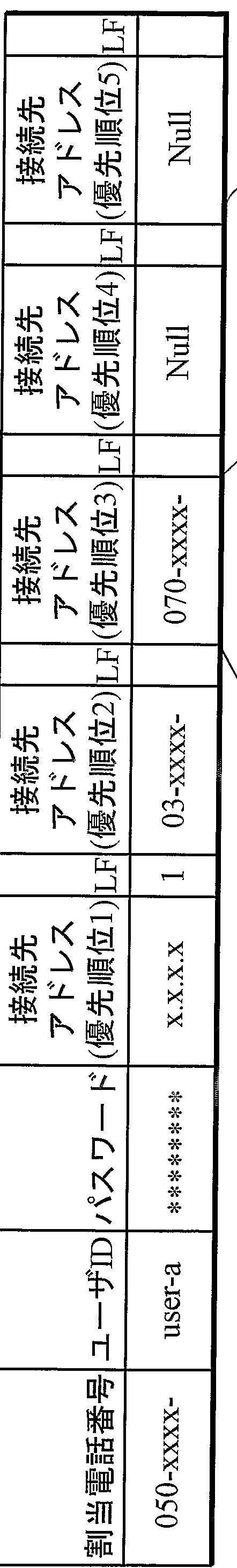
- the database server 12 stores, for example, information shown in a telephone number table 125a in FIG.
- the call agent 13 is based on the [050-XXXX-] shown in “Assigned Phone Numbers” in the phone number table 1 25a, and is listed in “Destination Address (Priority 1)”. Obtain the IP address [xxxx]. Based on the IP address [xxxx] obtained from the database server 12 and the IP address [yyyy] received from the IP phone terminal 26, the course agent 13 receives the IP phone terminal 26 Connect the phone terminal 2 1 u.
- the database server 12 has a predetermined telephone number. Can be stored.
- the assigned telephone number [050-XXX-] has the IP address [xxxx] stored as the above-mentioned "destination address (priority 1)".
- the telephone number of the general telephone terminal 31 used by the user U in the office 30 is set as the "connection destination address (priority 2)".
- [03 -XXXX-] is stored.
- the assigned telephone number [050-XXXX-] has a “destination address (priority 3)” as the telephone number [090-XXXX-] of the mobile telephone terminal 51 u used by user U. ] Is stored.
- the user U can store the telephone number of the general telephone terminal 31 and the telephone number of the mobile telephone terminal 51 u in the database server 12 via the Internet or the like.
- the call agent 13 calls the assigned telephone number ([050-XXXX-]) based on the priority of the connection destination address. Can be connected.
- the call agent 13 calls the IP telephone terminal 21 u based on the IP address [xxxx] stored as the connection destination address (priority order 1) J. If the telephone terminal 21 u does not answer the call from the call agent 13 within a predetermined time, the call to the IP telephone terminal 21 u is stopped, and the “connection destination address (priority 2)”
- the general telephone terminal 31 can be called based on the telephone number [03 -XXXX-] stored as.
- the priority order of a plurality of “destination addresses” stored in the database server 12 is determined by the user U by further storing predetermined information in the database server 12 according to the time of day. May be changed.
- a call for the telephone number [050-xxxx-] to be used can be connected to a predetermined telephone terminal.
- the user U when the user U connects the dedicated telephone terminal 60 u to the IP network 1 via the personal computer 70 u, the user U is assigned to the personal computer 70 u.
- the IP address is set via the SIP server 11 as the “connection destination address” stored in the database server 2 described above. The specific procedure for changing the “connection address” will be described later.
- the user U is stored in the database server 12 by connecting the dedicated telephone terminal 60 u to the IP network 1 via the personal computer 70 u at a business trip, for example. Yes, it is possible to answer a call to the telephone number [050-xxxx-] using the personal computer 7 Ou and the dedicated telephone terminal 6 Ou without changing the “connection destination address” by itself. it can.
- the user U Since the communication system according to the present embodiment operates as described above, the user U is connected to the IP telephone terminal 21 u and the dedicated telephone terminal 60 u to which the same telephone number [050-xxxx-] is assigned. This allows the two telephone terminals to be used separately without changing the connection destination address and other operations.
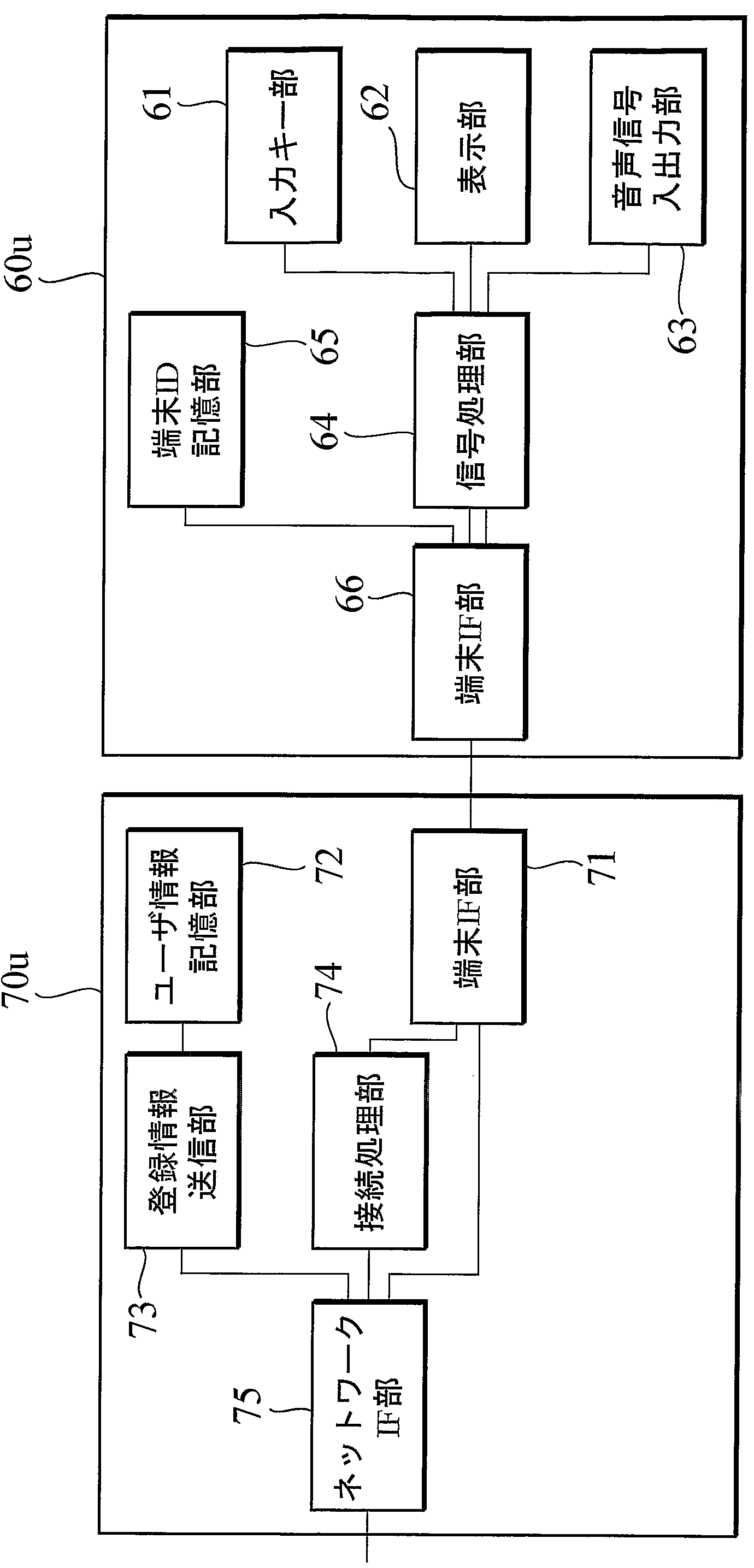
- the dedicated telephone terminal 6 O u has an input key section 61, a display section 62, an audio signal input / output section 63, a signal processing section 64, and a terminal ID storage section 65. And a terminal IF unit 6 6.
- the input key section 61 is for inputting numbers such as telephone numbers and predetermined characters. Numeric and character data entered by the input keys 6 1 Sent to processing section 64.
- the display unit 62 displays the content of data input by the input key unit 61, the telephone number of the transmission source, and the like, and is connected to the signal processing unit 64.
- the audio signal input / output unit 63 has a microphone and speed, and transmits and receives an audio band signal to and from the signal processing unit 64.
- the signal processing unit 64 converts an audio band signal transmitted and received between the audio signal input / output unit 63 and a digital signal based on a predetermined standard.
- the signal processing unit 64 is connected to the input key unit 61 and the display unit 62, and transmits and receives data such as telephone numbers.
- the signal processing unit 64 can be realized by, for example, a codec compliant with ITU-T G.729a / b. Further, the signal processing unit 64 converts the digitized voice signal and data such as a telephone number into IP packets, and transmits and receives IP packets to and from the terminal IF unit 66.
- the terminal ID storage unit 65 stores a terminal ID (terminal identifier) assigned to the dedicated telephone terminal 60u so that it can be read only by the personal computer 70u.
- the terminal ID assigned to the dedicated telephone terminal 60u is an identifier unique to the dedicated telephone terminal 60u.
- a serial number having a configuration of [Uxxxx-xxxx] is used.
- the terminal ID is stored in the database server 12 in association with the telephone number [050-XXXX-] used by the user U. Further, the terminal ID may use a MAC (Media Access Control) address assigned to the dedicated telephone terminal 60u instead of the serial number having the configuration of [Uxxxx-xxxx].
- MAC Media Access Control
- the terminal IF section 66 has an interface for connecting to a personal computer 7 O u.
- USB Universal Serial Bus
- IEEE802.11 IEEE802.311
- the personal computer 70 u has a terminal IF section 71, a user information storage section 72, a registration information transmission section 73, a connection processing section 74, and a network IF section 75. ing.
- the terminal IF unit 71 has an interface for connecting to the dedicated telephone terminal 60 u.
- the terminal IF unit 71 can be realized by a wireless LAN conforming to USB (Universal Serial Bus), IEEE802.11, or the like.
- the user information storage unit 72 stores a user ID (user identifier) for identifying the user U and a password associated with the user ID.
- the user ID [user-a] of the user U and the password associated with this user ID are stored.
- the user ID and password are stored in the database server 12 in association with the telephone number [050-XXXX-] used by the user U.
- the user ID and password stored in the user information storage unit 72 correspond to the terminal ID and the like. Since both are automatically sent to the SIP server 11, it is possible to prevent the user U from inputting information such as a user ID every time a connection is made.
- the registration information transmitting unit 73 is an IP network 1 that can communicate with the SIP server 11
- a terminal ID that identifies the dedicated telephone terminal 60 u and an IP network to which the personal computer 70 u is connected
- Terminal location address specifying the location of 1, ie, the IP address [x, .x, .x, .x,] specifying the location where the personal computer 70 u is connected to the IP network 1
- the SIP server 11 is sent to the SIP server 11.
- the registration information transmitting section 73 can further transmit the user ID and password of the user U to the SIP server 11. Whether to transmit the user ID and the password in addition to the terminal ID and the IP address may be determined according to the security level to be secured.
- the connection processing unit 74 communicates with the SIP server 11 via the network IF unit 75. Specifically, the connection processing unit 74 performs the terminal ID [U1234-5678] and the IP address [x'.x'.x, .x based on the SIP (Session Initiation Protocol). ,], User ID [user-a] and password are sent to the SIP server 11. Further, when the transmitted IP address [x, .x, .x,. X ,] is registered in the database server 12, the connection processing unit 74 sends the IP address from the SIP server 11 to the corresponding IP address. Receives information indicating the registration validity period ("expires" parameter of the SIP header).
- the connection processing unit 74 Based on the received information indicating the registration validity period of the IP address, the connection processing unit 74 sends the IP address, the user ID and the passcode again before the expiration of the registration validity period to the SIP server. Sent to 1 to make the database server 12 re-register the IP address.
- connection processing unit 74 communicates with the SIP server 11 and the dedicated telephone terminal 60 u, that is, the call to the telephone number [050-XXXX-] used by the user U, based on the SIP (Session Initiation Protocol). Perform the connection. Further, the connection processing unit 74 periodically checks whether the dedicated telephone terminal 60 u is connected to the personal computer 70 u via the terminal IF unit 1. Specialty When the telephone terminal for use 60 u is disconnected from the terminal IF unit 71, the connection processing unit 74 notifies the SIP server 11 of the disconnection.
- the network IF unit 75 has an interface that can be connected to the IP network 1.
- the network IF unit 75 can be realized by a LAN interface such as 100BASE-TX conforming to IEEE802.3U.
- the connection between the IP network 1 and the personal computer 70 u uses an ADSL (Asymmetric Digital Subscriber Line) modem or the like according to the status of the access line connected to the IP network 1. You can do that too.
- ADSL Asymmetric Digital Subscriber Line
- the SIP server 11 has a network IF section 111, a registration information receiving section 112, a communication section 113, a call connection section 114, and a terminal connection section. And a detection unit 1 15.
- the network IF unit 11 1 includes an interface for connecting to the database server 12, the call agent 13, and the IP network 1.
- the network IF unit 111 can be realized by a LAN interface such as 100BASE-TX or 1000BASE-TX.
- the registration information receiving unit 112 includes a terminal ID [U1234-5678] of the dedicated telephone terminal 60 u and an IP address [ ⁇ , ⁇ ] indicating the position of the IP network 1 to which the personal computer 70 u is connected. . ⁇ '. ⁇ , ⁇ ⁇ ,].
- the registration information receiving unit 1 1 2 applies the terminal ID [U1234-5678] and the IP address [ ⁇ '. ⁇ ' . ⁇ '. ⁇ '] to [!
- the user ID [user_a] and the password can be further received.
- the registration information receiving unit 1 1 2 Transmitting the ID [U 1234-5678], IP address [x, .x, .x, .x ,] a, and the user ID [user one a], and Nono 0 scan Wa one de the database server 1 2 I do.
- the communication unit 113 communicates with the personal computer 70u based on SIP.
- the communication unit 113 uses the “REGISTER” message specified in the SIP to transmit the IP address [ ⁇ , . ⁇ , . ⁇ , . ⁇ ,], terminal ID [U 1234-5678], the user ID [user_a] and the password are received from the personal computer 70 u or the dedicated telephone terminal 60 u. Further, when the IP address [x, .x, .x, .x,] is registered in the database server 12, the communication unit 113 transmits information indicating the registration validity period of the IP address. Send the response including personal information to the personal computer 7 Ou. In this embodiment, the communication unit 113 can arbitrarily specify the registration validity period of the IP address [ ⁇ , ⁇ ⁇ , . ⁇ , . ⁇ '] by using the “expires” parameter of the SIP header. .
- the call connection unit 114 connects a call for the telephone number [050- ⁇ -] used by the user U to the personal computer 70 u based on the notification from the call agent 13. .
- the terminal connection detection section 1 15 detects that the personal computer 7 Oukara dedicated telephone terminal 60 u connected to the IP network 1 has been disconnected from the IP network 1. Yes, in the present embodiment, a detection unit is configured.
- the terminal connection detection unit 1 15 transmits the registration validity period of the IP address 0,...,] Transmitted to the personal computer 7 O u by the communication unit 1 13. Also, if there is no re-registration from the personal computer 7 Ou, it instructs the call connection section 114 to call the dedicated telephone terminal 60 u. If the dedicated telephone terminal 60u does not answer the call from the call connection unit 114 within a predetermined time, the terminal connection detection unit 115 It is determined that the user 70 u has been disconnected from the IP network 1.
- the terminal connection detection unit 115 determines that the dedicated telephone terminal 60 u is not connected, the terminal connection detection unit 115 notifies the database server 12 that the dedicated telephone terminal 60 u has been disconnected from the IP network 1. I do.
- the database server 12 includes a network IF section 121, a user IF section 122, an authentication section 123, a setting updating section 124, and a storage section 125. And
- the storage unit 125 stores the telephone number (eg, [050-XXXX-]) used by the user, the connection destination address, and the terminal identifier in association with each other. Further, the storage unit 125 stores the user ID (eg, [user-a]) for identifying the user who uses the telephone number such as [050-XXXX-] and the password associated with the user ID. 050-XXXX-] or the like. More specifically, the storage unit 125 includes a telephone number table 125a, a terminal ID table 125b, and a power.
- the telephone number eg, [050-XXXX-]
- the storage unit 125 includes a telephone number table 125a, a terminal ID table 125b, and a power.
- the telephone number table 1 25a includes “assigned telephone number”, “user ID”, “password”, “connection destination address (priority order 1 to 5)”, and the connection destination address. "LFJ (Location Free)", which indicates that is assigned to a personal computer 70 u.
- terminal ID table 125 b “assigned telephone numbers” and “terminal IDs” are associated, and “assigned telephone numbers” correspond to “assigned telephone numbers” in the telephone number table 125 a. are doing.
- the network IF unit 121 has an interface for connecting to the SIP server 11 and the call agent 13.
- Net Network IF section 121 can be realized by a LAN interface such as 100BASE-TX or 1000BASE-TX.
- the user IF unit 122 provides an interface for the user U to register the call transfer destination for the telephone number [050-xxxx-] used by the user U.
- the user IF unit 122 can be realized by a Web server connected to the Internet.
- the user IF unit 122 stores the information such as the telephone number acquired from the user U in the storage unit 125 via the setting updating unit 124.
- the authentication unit 123 is a terminal that is received by the SIP server 111.
- the dedicated telephone terminal 60 u is authenticated based on the ID [U1234-5678] and the terminal ID of the dedicated telephone terminal 60 u stored in the storage unit 1 25 (terminal ID table 125 b). Things.
- the authentication unit 123 is a terminal that is received by the SIP server 111.
- the storage unit 125 (telephone number table 125a) By confirming the user ID [user_a] and password stored in the dedicated telephone terminal 60u, the dedicated telephone terminal 60u can be authenticated.
- the setting update unit 124 sets the IP address [x'.x'.x ,. x,] and the telephone number [050] stored in the storage unit 125 (telephone number table 125a) in association with the terminal ID [U1234-5678] also received by the SIP server 111. -xxxx] and the IP address [x, .x, .x, .x,] is stored in the storage unit 125 (telephone number table 125a). This is set as a priority connection destination that has priority over “.”, And in this embodiment, a priority connection destination setting unit is configured.
- FIG. 6 shows the state after the setting updating unit 124 has executed the above-described processing. It shows the contents of the storage unit 125 (telephone number table 125a).
- the IP address assigned to the personal computer 70 u is assigned to the “destination address (priority 1)” associated with the telephone number [050-XXXX-]
- the IP address of the IP telephone terminal 21 u stored in the “connection destination address (priority order 1)” until the above processing is completed.
- [x.x.x.x] is stored in the “destination address (priority order 2)”.
- the phone numbers [03-XXXX-] and [090-XXX-] are similarly prioritized.
- the setting updating unit 124 is set when the terminal connection detecting unit 115 of the SIP server 111 detects that the dedicated telephone terminal 60 u has been disconnected from the IP network 1.
- the data is stored in the storage unit 125 in advance.
- the call to the telephone number [050-XXX-] can be connected based on the information of the “address to connect to”.
- ⁇ ,.,. 0 u may be deleted each time it is disconnected from the IP network 1 or may be deleted again in a predetermined area of the storage unit 125 for a certain period in consideration of being connected again by the same IP address. It may be stored.
- the setting update unit 124 stores the contents such as the telephone number and the like acquired from the user U transmitted by the user IF unit 122 (the telephone number table 125a). ) Can be stored.
- the call agent 13 has a network IF unit 131, a call connection unit 132, and a GW information storage unit 133.
- the network IF section 13 1 has an interface for connecting to the SIP server 11, the database server 12, and the IP network 1.
- the network IF unit 131 can be realized by a LAN interface such as 100BASE-TX or 1000BASE-TX.
- the call connection unit 132 when the priority connection destination, that is, the IP address [x, .x'.x, .x,] is set in the telephone number table 125a of the database server 12, A call for the telephone number [050-XXX-] is connected to the dedicated telephone terminal 60 u based on the IP address [ ⁇ '. ⁇ '.
- a call connection unit is constituted by the call connection unit 114 and the call connection unit 132 of the SIP server 11.
- the call connection unit 132 receives a call for the telephone number [050-XXXX-], it is stored in the telephone number table 125a based on the telephone number [050-XXXX-].
- [1] is displayed in “LF” of “Destination address (priority 1)” associated with the telephone number [050-XXXX-]
- the call connection unit 13 The SIP server 11 stores the IP address [x'.x, .x, .x,] stored in the telephone number table 1 25a and the IP address of the source of the call.
- the call connection unit 132 is a telephone number to be connected to the “connection destination address” of the telephone number table 125a via the gateway 1G, that is,
- the GW information storage unit 133 stores the IP address of the gateway 1 G connecting the IP network 1, the PSTN 2 or the mobile phone network 3, and the telephone number to be connected via the gateway. Are stored in association with each other. For example, in the present embodiment, the IP address of the gateway 1G connected to the PSTN 2 and the telephone number starting with [03] are stored in association with each other.
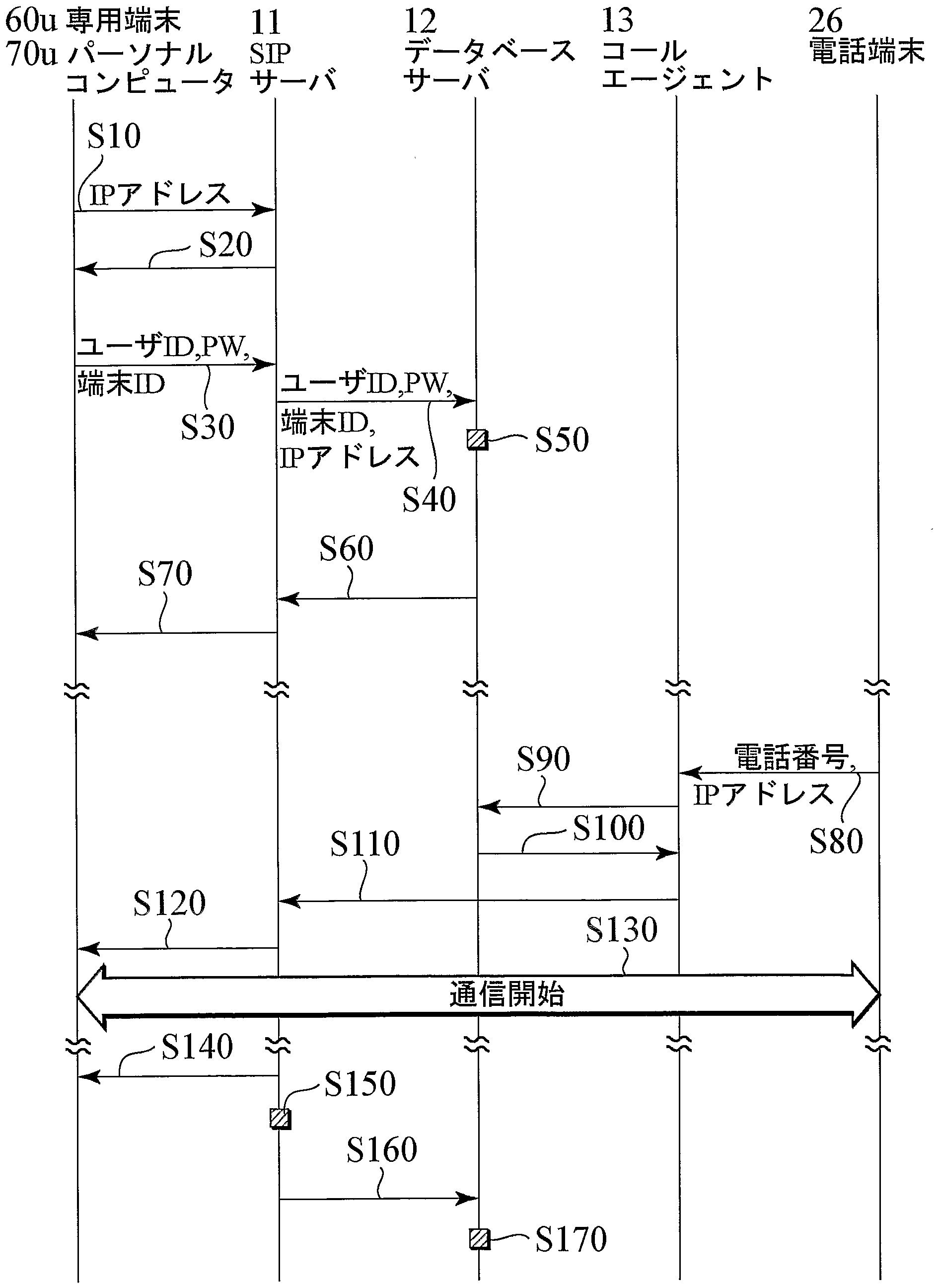
- the personal computer 70 u uses the SIP “REGISTER” message to The IP address [x, .x, .x, .x,] assigned to the personal computer 70u is transmitted to the SIP server 11 (S10).
- the SIP server 11 that has received the "REGISTER” message transmits a challenge value based on an ano-registration mechanism such as MD5 (S20).
- the personal computer 70 u Upon receiving the challenge value, the personal computer 70 u receives the user ID [user-a], the password associated with the user ID, and the terminal ID [U1234 stored in the dedicated telephone terminal 60 u. -5678]
- the value calculated by the algorithm such as MD5 is transmitted to the SIP server 11 (S30).
- the SIP server 11 sends the user ID [user-a], password, terminal ID [U1234-5678], and IP address [ ⁇ ⁇ ⁇ ⁇ ⁇ ⁇ , ⁇ ⁇ ] received from the personal computer 70 u. '. ⁇ , . ⁇ ,] to the database server 12 (S40).
- the database server 12 stores information and data received from the SIP server 11 Based on the information stored in the base server 12, the dedicated telephone terminal 6 Ou is authenticated, and the “connection destination address (priority 1)” is changed to the IP address'.,. Change (S50).
- the database server 12 notifies the SIP server 11 that the dedicated telephone terminal 60u has been authenticated and has updated the contents of the "connection destination address (priority order 1)" (S60).
- the SIP server 11 notifies the personal computer 70u of the completion of the registration based on the notification from the database server 12 (S70). In addition, the SIP server 11 notifies the IP address
- the call agent 13 identifies the telephone number and the IP address [yyyy] of the IP telephone terminal 26. It is received from the IP telephone terminal 26 (S80). Next, the call agent 13 refers to the contents stored in the database server 12 based on the received telephone number [050-XXXX-] (S90). Here, the call agent 13 obtains the IP address
- the call agent 1 3 IP a
- the address [ ⁇ , ⁇ ⁇ , . ⁇ , . ⁇ ,] and the IP address [yyyy] of the IP telephone terminal 26 are transmitted to the SIP server 11 (S11). 0).
- the SIP server 11 connects the call from the IP telephone terminal 26 to the dedicated telephone terminal 60u based on the information received from the call agent 13 (S120). Thereafter, communication is started between the IP telephone terminal 26 and the dedicated telephone terminal 60u (S130).
- step S 70 Even if the registration validity period of the IP address [ ⁇ '. ⁇ '. ⁇ '. ⁇ '] notified to the personal computer 70 u in step S 70 has passed, the SIP server 11 If the IP address is not re-registered from 0u, the dedicated telephone terminal 60u connected to the personal computer 7Ou is called (S140).
- the SIP server 11 determines that the personal computer 70 u has been disconnected from the IP network 1 (S 1 5 0).
- the personal computer 70u determines that the dedicated telephone terminal 60u has been disconnected based on the SIP server. 11 can also be notified.
- the SIP server 11 is dedicated to the database server 12 based on the result of the determination in step S150 or a notification from the personal computer 70u indicating that the dedicated telephone terminal 60u has been disconnected. Notify that the telephone terminal 600 u or the personal computer 70 ou has been disconnected (S 160).
- the database server 1 2 Based on the notification from the SIP server 11, the database server 1 2 sets the priority connection destination of the call for the telephone number [050-XXX-], that is, the telephone number Disassociate [050-xxxx-] from the IP address [ ⁇ '. ⁇ ' . ⁇ '. ⁇ '] (S170)
- the processing of step S170 is completed,
- the information stored in the database server 12 is changed to the contents shown in Fig. 4. (Operation and Effect of Communication System and Communication Method According to this Embodiment)
- the call for user U's telephone number [050-XXXX-] is connected to the dedicated telephone terminal 60 u, so user U can access telephone number [050-XXXX-].
- the call can be answered using the dedicated telephone terminal 60 u.
- the IP address [x, .x, .x, .x,] transmitted by the personal computer 70u is stored in the connection destination address stored in the database server 12 in advance. Since the connection destination is automatically set as the priority connection destination prior to the address, it is possible to prevent the user U from manually changing the connection destination address. That is, user U connects two telephone terminals, an IP telephone terminal 21 u and a dedicated telephone terminal 60 u to which the same telephone number [050-XXXX-] is assigned.
- the dedicated telephone terminal 60 u is authenticated based on the terminal ID transmitted from the dedicated telephone terminal 60 u and the terminal ID stored in the database server 12, the user It is possible to determine whether the service can be provided to the dedicated telephone terminal 60u without using the user ID and password of U.
- the dedicated telephone terminal 60 u is disconnected from the personal computer 70 u by the SIP server 11 or the personal computer 70 u is disconnected from the IP network 1. Is detected, the set preferred access point is released and When the dedicated telephone terminal 60 u or the personal computer 70 u is disconnected from the IP network 1, the agent 13 is a connection destination address stored in advance in the database server 12. The call to the telephone number [050-XXXX-] can be connected based on the.
- the dedicated telephone terminal 60u in addition to the terminal ID transmitted from the dedicated telephone terminal 60u, the dedicated telephone terminal 60u is authenticated based on the user ID and the password, so that security against use of unauthorized services is improved. Can be improved.
- the dedicated telephone terminal 60 u further includes a terminal ID storage unit 65 that can only read a terminal ID, and the registration information transmitting unit 73 reads out from the terminal ID storage unit 65. Since the terminal ID is transmitted, the terminal ID can be prevented from being changed by the user or the like, and the security against unauthorized use of the service can be improved.
- the personal computer 70 u further includes a user information storage unit 72 for storing a user ID and a password
- the registration information transmitting unit 73 includes a terminal ID and a user information storage unit 7. Since the user ID and password stored in 2 are transmitted, it is possible to avoid the user U from inputting the user ID and password for each connection.
- the terminal device described in the first embodiment is connected to the IP network 1 through wireless communication with the general wireless base station 3B or the private base station device 10Ou. It is composed of a portable terminal device 90 u that can be connected and a private base station device 100 u that can be connected to the IP network 1.
- the mobile terminal device 90 u is carried by the user U and is capable of mobile communication, is assigned a telephone number [070-XXXX-], and has an IP address '.x' .X ' ⁇ ⁇ '] is assigned.
- the mobile terminal device 90 u performs wireless communication with the wireless base station 3 ⁇ using a PHS protocol, and transmits the mobile telephone network 3 to the IP network 1 via the wireless base station 3 ⁇ . Access to the Internet, and VoIP technology enables IP telephony through the IP network1.
- this portable terminal device 9 Ou uses the same protocol as the protocol used in the wireless base station 3 B, and uses the PHS protocol protocol for wireless communication with the self-managed base station device 100 u. It is possible to access the IP network 1 through the self-managed base station device 100u, and also to make an IP phone call via the IP network 1. Further, the portable terminal device 900u can be connected to the self-managed base station device 100u also through a wireless LAN such as IEEE802.il, and an IP telephone can be made through this wireless LAN. The connection between the PHS method and the wireless LAN method can be switched automatically according to the communication environment (radio wave condition) or based on a user operation.
- the private base station apparatus 100 u is a dedicated terminal adapter 80 u or IP telephone terminal 21 u described above with the addition of a PHS system private base station means and a wireless LAN function, and is connected to this.
- the self-operating base station apparatus 100 u performs the same function as the above-described wireless base station 3 B within a predetermined value range in which the radio wave reaches, and thereby, the user U Even in a place where radio waves from the wireless base station 3B do not reach, PHS communication can be performed through the self-managed base station apparatus 10Ou.
- the self-supporting base station apparatus lOOu includes a PHS wireless communication and a wireless LAN switching switch 101a. Method and wireless LAN can be switched arbitrarily. Monkey.
- the self-operating base station apparatus 100u has the above-described self-operating base station function in the form of an antenna adapter, and is inserted into a personal computer 70u to provide a personal computer 700u. It may be configured in cooperation with the function of u.
- the card slot of the computer 7 Ou is an adapter type that can be attached to and detached from the USB slot, and the personal computer has a communication antenna function for wireless communication with the portable terminal device 90 u. Add to 70 u.
- the mobile terminal device 90 u includes an input key unit 91, a display unit 92, an audio signal input / output unit 93, a signal processing unit 94, and a connection processing unit 99. have.
- the input key section 91 is for inputting numbers such as telephone numbers and predetermined characters.
- the numeric and character data input by the input key unit 91 is transmitted to the signal processing unit 94.
- the display section 92 displays the contents of data input by the input key section 91, the telephone number of the caller, and the like, and is connected to the signal processing section 94.
- the audio signal input / output unit 93 has a microphone and a speaker, and transmits and receives an audio band signal to and from the signal processing unit 94.
- the signal processing unit 94 converts an audio band signal transmitted / received between the audio signal input / output unit 93 and a digital signal based on a predetermined standard, and converts the converted digital signal into an IP packet. This is a module that converts to.
- the signal processing unit 94 is connected to the input key unit 91 and the display unit 92, and transmits and receives data such as telephone numbers.
- the signal processing unit 94 can be realized by, for example, a codec or the like based on ITU-T G.729a / b. Further, the signal processing unit 94 converts the digitized voice signal and data such as a telephone number into an IP bucket.
- the connection processing unit 99 is a module that communicates with the SIP server 11 when directly connecting to the wireless base station 3b through the 113 unit 97. Specifically, the connection processing unit 104 performs the above-described terminal ID [U1234-5678], IP address [x, .x '.'. '], User based on SIP (Session Initiation Protocol). The ID [user-a] and the password are transmitted to the SIP server 11. Further, when the transmitted IP address, .x '. ⁇ ' ⁇ ⁇ ':], is registered in the database server 12, the connection processing section 104 sends the IP address of the IP address from the SIP server 11. Receives information indicating the registration validity period (“expires” parameter in the SIP header).
- connection processing unit 99 based on the received information indicating the validity period of the IP address, transmits the IP address, the user ID, and the passcode again before the validity period of the registration to the SIP server. Send to 1 and make the database server 12 re-register the IP address. Further, when directly connecting to the wireless base station 3b, the connection processing unit 99, based on the SIP (Session Initiation Protocol), communicates with the SIP server 11 and the portable terminal device 90u, that is, the user U. Execute the call connection for the telephone number [070-XXXX-] to be used.
- SIP Session Initiation Protocol
- the portable terminal device 90u has a registration information transmitting unit 95a, a user information storage unit 95b, and a terminal ID storage unit 95c.
- the user information storage section 95b stores a user ID (user identifier) for identifying the user U and a password associated with the user ID.
- the user ID [user-a] of the user U and the password associated with this user ID are stored.
- the user ID and the password are stored in the database server 12 in association with the telephone number [070-XXXX-] used by the user U.
- the mobile terminal device 90 u When the mobile terminal device 90 u is connected to the IP network 1, it is automatically transmitted to the SIP server 11 together with the user ID, password, terminal ID, etc. stored in the user information storage unit 95 b. Information such as a user ID every time a connection is established. User U can be prevented from inputting.
- the registration information transmitting unit 95 a transmits a terminal ID for identifying the portable terminal device 90 u and an IP network.
- a terminal location address for specifying the location of the network 1, that is, an IP address [ ⁇ '. ⁇ ' . ⁇ '. ⁇ '] for identifying a location where the portable terminal device 90 u is connected to the IP network 1. Is sent to the SIP server 11.
- the registration information transmitting section 95a can further transmit the user ID and the password of the user U to the SIP server 11. Whether to transmit the user ID and the password in addition to the terminal ID and the IP address may be determined according to the security level to be secured.
- the terminal ID storage unit 95c is a storage memory for transmitting a terminal ID (terminal identifier) assigned to the portable terminal device 90u to the registration information transmitting unit 95a.
- the terminal ID assigned to the mobile terminal device 90u is an identifier unique to the mobile terminal device 90u.
- a serial number having a configuration of [Uxxxx-xxxx] is used, and [U1234-5678] is assigned to the portable terminal device 90 u.
- the terminal ID is stored in the database server 12 in association with the telephone number [070-XXXX-] used by the user U.
- the terminal ID is
- MAC Media Access Control
- serial number is written in FLASH or the like so that the contents for the purpose of unauthorized use of the IP telephone service cannot be rewritten. Therefore, it is difficult to easily change the serial number, and the security against the use of the unauthorized IP telephone service can be improved.
- the mobile terminal device 90 u includes a PHS unit 97, which is a communication interface for performing wireless communication using a PHS communication protocol, and a
- a wireless LAN unit 98 which is a communication interface for short-range communication such as LAN, these?
- a switching section 96 for switching between the 3 section 97 and the wireless LAN section 98 is provided.
- the PHS unit 97 is a module that performs wireless communication using a PHS protocol between the wireless base station 3B and the private PHS unit 106 provided in the private base station device 100u. is there.
- the wireless LAN unit 98 is a module that performs wireless communication with the wireless LAN unit 107 provided in the self-managed base station 100u by a method based on IEEE802.il or the like.
- the switching section 96 selectively signals the PHS section 97 and the wireless LAN section 98 based on a user operation through the input key section 91 and the determination of the received signal strength in the signal processing section 94. This is a switch connected to the processing unit 94.
- the self-managed base station 100 u has a connection processing unit 104 and a network IF unit 105.
- the connection processing unit 104 is a module that communicates with the SIP server 11 via the network IF unit 105. Specifically, the connection processing unit 104 performs the above-mentioned terminal ID [U1234-5678], IP address [x'.x'.x'.x,], based on SIP (Session Initiation Protocol). The user ID [user_a] and password are transmitted to the SIP server 11. Further, when the transmitted IP address [x, .x ' ⁇ ⁇ ' . ⁇ '] is registered in the database server 12, the connection processing unit 104 receives the IP address from the SIP server 11. Receives information indicating the validity period of the dress registration ("expires" parameter in the SIP header).
- connection processing unit 104 sends the IP address, the user ID and the passcode again before the expiration of the registration validity period, based on the received information indicating the validity period of the registration of the IP address. 1 to cause the database server 12 to re-register the IP address.
- the connection processing unit 104 communicates with the SIP server 11 1 based on the SIP (Session Initiation Protocol) with the mobile terminal device 90 u, that is, the call to the telephone number [070-XXXX-] used by the user U. To execute the connection. Furthermore, the connection processing unit 10 Step 4 periodically checks whether the portable terminal device 900u is connected to the own base station device 100u. When the mobile terminal device 900 is disconnected from the self-service base station device 100 u, the connection processing unit 104 notifies the SIP server 11 of the disconnection.
- the network IF unit 105 has an interface connectable to the IP network 1. For example, the network IF unit 105
- LAN interface such as 100BASE-TX compliant with IEEE802.3U.
- An ADSL (Asymmetric Digital Subscriber Line) modem or the like can be used for connection between the IP network 1 and the private base station 100 u depending on the status of the access line connected to the IP network 1. .
- the self-owned base station apparatus 100 u is connected to a self-managed PHS section 106, which is a communication interface for performing wireless communication using a PHS communication protocol, and a communication interface for short-range communication such as a wireless LAN. It has a wireless LAN unit 107 as an interface, and a switching unit 108 for switching between the self-managed PHS unit 106 and the wireless LAN unit 107.
- the self-managed PHS unit 106 is a module that performs wireless communication with the PHS unit 97 provided in the portable terminal device 90u using a PHS protocol.
- the wireless LAN unit 107 is a module that performs wireless communication with the wireless LAN unit 98 provided in the portable terminal device 90u by a method based on IEEE802.il or the like.
- the switching unit 108 wirelessly communicates with the self-managed PHS unit 106 based on the user operation through the switch 101a and the judgment of the received radio wave intensity in the self-managed PHS unit 106 and the wireless LAN unit 107. This is a switching switch for selectively connecting the LAN unit 107 to the connection processing unit 104 and the network IF unit 105.
- FIG. 10 is an explanatory diagram showing the operation of the communication system.
- a user at user home 25 uses IP telephone terminal 26 to connect to user home 20.
- the call agent 13 transmits the telephone number [050] harmed to the IP telephone terminal 21 u.
- -XXXX-] is received from the IP telephone terminal 26 together with the IP address [yyyy].
- the call agent 13 refers to the database server 12 based on the received telephone number [050-XXXX-].
- the database server 12 stores, for example, information shown in a telephone number table 125a of FIG. Based on [050-XXXX-] shown in “Assigned telephone number” in the telephone number table 12 25a, the call agent 13 is shown in “Destination address (priority 1)”. Obtain the current IP address [xxxx]. Based on the IP address [xxxx] obtained from the database server 12 and the IP address [yyyy] received from the IP telephone terminal 26, the call agent 13 and the IP telephone terminal 26 and the IP telephone terminal 2 1 Connect with u.
- the database server 12 can store a transfer destination telephone number to which a call corresponding to a predetermined telephone number is transferred.
- the assigned telephone number [050-XXXX-] includes, in addition to the IP address [xxxx] stored as the above-mentioned “destination address (priority 1)”,
- the telephone number [070-xxxx-] of the mobile terminal device 9Ou carried by the user U is stored as the "connection destination address (priority order 4)".
- the telephone number table 125a has a hierarchical structure, and the lower table 125c of the assigned telephone number [070-XXXX-] is connected to the portable terminal device 90u.
- the IP address of the possible self-service base station device 100 u is stored.
- the IP address [[xl.xl.xl.xl] of the self-service base station apparatus 100u installed in the office 30 of the user U is stored as the “connection destination address (priority order 2)”.
- the “connection destination address (priority 3)” is the IP address of the self-managed base station device 100 u attached to the personal computer 70 u used by the user U.
- [[x2.x2.x2.x21 is stored. Note that user U can access the Internet via the Internet, etc. Thus, the telephone number of the general telephone terminal 31 and the telephone number of the mobile telephone terminal 51 u can be stored in the database server 12.
- the call agent 13 sends a call to the assigned telephone number ([050-XXXX-]) based on the priority of the connection destination address. Can be connected.
- the call agent 13 calls the IP telephone terminal 21 u based on the IP address [xxxx] stored as the “connection destination address (priority order 1)”, but the IP telephone terminal 2 If 1 u does not answer the call from the call agent 13 within a predetermined time, the call to the IP telephone terminal 21 u is stopped, and the call is stored as the “destination address (priority 2)”.
- the general telephone terminal 31 can be called based on the telephone number [03-XXXX-].
- the call agent 13 calls the telephone number [070-xxxx-] directly by the PHS method, and if the call agent 13 does not answer within a predetermined time, the call agent 13 becomes self-employed. A call is made through the IP address of the base station apparatus 100 u. Note that the priority order of a plurality of “destination addresses” stored in the database server 12 is changed according to the time of the day by allowing the user U to further store predetermined information in the database server 12. You may.
- the database server 1 2 and the call agent 1 3 by operating as described above, depending on where the user is present U, the user U Use telephone number [050-XXXX-] predetermined telephone call for the Can be connected to the terminal.
- the user U when the user U connects the portable terminal device 90 u to the IP network 1 via the private base station device 100 u, the user U is assigned to the connected private base station device 100 U.
- the IP address is set via the SIP server 11 as the “connection destination address” stored in the database server 12 described above.
- the user U can use the self-owned base station device 100 at a business trip destination, for example.
- the telephone number [050-XXXX-] can be used without changing the “connection destination address” stored in the database server 12. ] Can be answered using the private base station apparatus 100 u and the portable terminal apparatus 90 u.
- the user U Since the communication system according to the present embodiment operates as described above, the user U is connected to the IP telephone terminal 21 u and the dedicated telephone terminal 60 u to which the same telephone number [050-XXXX-] is assigned. This allows the two telephone terminals to be used properly without changing the “connection destination address”.
- the PHS system communication with the mobile terminal device 90 u is enabled by the self-managed base station device 100 u, and thus the user is assigned to the mobile terminal device 90 u.
- IP phones can be used using PHS phone numbers.
- the self-managed base station apparatus 100 u is an antenna adapter that can be attached to and detached from the personal computer 70 u, by carrying this antenna adapter, the wireless base station 3 B Even if the radio wave is not reachable, if you have a personal computer that can connect to the IP network 1, you can build a self-owned PHS antenna station. You can use the phone.
- a terminal device automatically transmits information for identifying the terminal device and information indicating a position on the network, and calls based on the transmitted information.
- the connection server By changing the information of the connection server, it is possible to provide a communication system, a call connection server, a terminal device, and a communication method capable of connecting a call for a predetermined telephone number to the terminal device.
Abstract
Description
Claims


Priority Applications (5)
| Application Number | Priority Date | Filing Date | Title |
|---|---|---|---|
| EP03775869A EP1650940A4 (en) | 2003-07-30 | 2003-11-21 | Communication system, call connection server, terminal apparatus and communication method |
| AU2003284437A AU2003284437A1 (en) | 2003-07-30 | 2003-11-21 | Communication system, call connection server, terminal apparatus and communication method |
| US10/566,271 US7460521B2 (en) | 2003-07-30 | 2003-11-21 | Communication system, call connection server, terminal apparatus and communication method |
| JP2005507415A JP4478109B2 (en) | 2003-07-30 | 2003-11-21 | Communication system, call connection server, terminal device, and communication method |
| TW093105411A TW200507549A (en) | 2003-07-30 | 2004-03-02 | Communication system, call connection server, terminal apparatus and communication method |
Applications Claiming Priority (2)
| Application Number | Priority Date | Filing Date | Title |
|---|---|---|---|
| JP2003-283009 | 2003-07-30 | ||
| JP2003283009 | 2003-07-30 |
Publications (1)
| Publication Number | Publication Date |
|---|---|
| WO2005013590A1 true WO2005013590A1 (en) | 2005-02-10 |
Family
ID=34113795
Family Applications (1)
| Application Number | Title | Priority Date | Filing Date |
|---|---|---|---|
| PCT/JP2003/014939 WO2005013590A1 (en) | 2003-07-30 | 2003-11-21 | Communication system, call connection server, terminal apparatus and communication method |
Country Status (8)
| Country | Link |
|---|---|
| US (1) | US7460521B2 (en) |
| EP (1) | EP1650940A4 (en) |
| JP (1) | JP4478109B2 (en) |
| KR (1) | KR20060117901A (en) |
| CN (1) | CN1820490A (en) |
| AU (1) | AU2003284437A1 (en) |
| TW (1) | TW200507549A (en) |
| WO (1) | WO2005013590A1 (en) |
Cited By (9)
| Publication number | Priority date | Publication date | Assignee | Title |
|---|---|---|---|---|
| US20070258111A1 (en) * | 2006-03-29 | 2007-11-08 | Nec Access Technica, Ltd. | Sip adapter and sip communication system |
| JP2008022363A (en) * | 2006-07-13 | 2008-01-31 | Fujitsu Ltd | Communication system and subscriber terminal |
| WO2008015866A1 (en) * | 2006-08-04 | 2008-02-07 | Nec Corporation | Setting information registering apparatus, wireless communication system, setting information registering method and setting information registering program |
| CN1832591B (en) * | 2005-03-07 | 2010-05-26 | Lg电子株式会社 | Method for transmitting messages in mobile communications system and mobile communications terminal |
| US20110228691A1 (en) * | 2007-07-10 | 2011-09-22 | Qualcomm Incorporated | Methods and appartus for controlling interference to broadcast signaling in a peer to peer network |
| JP2012257104A (en) * | 2011-06-09 | 2012-12-27 | Nippon Telegr & Teleph Corp <Ntt> | Call connection processing device, and operation method therefor |
| US8495232B2 (en) | 2007-07-10 | 2013-07-23 | Qualcomm Incorporated | Methods and apparatus for supporting broadcast communications in a peer to peer network |
| US8694662B2 (en) | 2007-07-10 | 2014-04-08 | Qualcomm Incorporated | Method and apparatus for communicating transmission requests to members of a group and/or making group related transmission decisions |
| US8861418B2 (en) | 2007-07-10 | 2014-10-14 | Qualcomm Incorporated | Methods and apparatus for supporting group communications with data re-transmission support |
Families Citing this family (28)
| Publication number | Priority date | Publication date | Assignee | Title |
|---|---|---|---|---|
| JP4574366B2 (en) * | 2004-03-30 | 2010-11-04 | 要二 竹内 | CD-ROM, management server, operation server, and IP telephone terminal registration method in which a program for functioning as an IP telephone terminal is recorded |
| JP2006019986A (en) * | 2004-06-30 | 2006-01-19 | Toshiba Corp | Telephone terminal of network telephone system and power feeding method used by the same telephone terminal |
| JP4516375B2 (en) * | 2004-08-06 | 2010-08-04 | パナソニック株式会社 | Call connection control device and IP telephone system |
| DE102004043969A1 (en) * | 2004-09-11 | 2006-03-16 | Deutsche Thomson-Brandt Gmbh | Network connection switching unit |
| US8060070B2 (en) * | 2004-12-22 | 2011-11-15 | Research In Motion Limited | System and method for redirecting communications for a mobile device |
| KR100693054B1 (en) * | 2005-01-19 | 2007-03-12 | 삼성전자주식회사 | apparatus and method for call processing in network system based wireless LAN |
| CN101102583A (en) * | 2006-07-05 | 2008-01-09 | 华为技术有限公司 | Using method and device for user terminal identifier |
| US20080075064A1 (en) * | 2006-08-30 | 2008-03-27 | Microsoft Corporation | Device to PC authentication for real time communications |
| CN100438448C (en) * | 2006-09-14 | 2008-11-26 | 华为技术有限公司 | Method and device for implementing network call after network failure |
| US9094784B2 (en) * | 2006-10-10 | 2015-07-28 | Qualcomm Incorporated | Registration of a terminal with a location server for user plane location |
| US20080137643A1 (en) * | 2006-12-08 | 2008-06-12 | Microsoft Corporation | Accessing call control functions from an associated device |
| US20080304473A1 (en) * | 2007-06-11 | 2008-12-11 | At&T Corp. | Enhanced terminal adapter |
| US8270958B2 (en) * | 2007-06-20 | 2012-09-18 | Verizon Patent And Licensing Inc. | Apparatus, system and method for automated communication forwarding |
| WO2009016760A1 (en) * | 2007-08-02 | 2009-02-05 | Fujitsu Limited | Telephone system, communication system, and computer program |
| JP5164583B2 (en) * | 2008-01-21 | 2013-03-21 | 株式会社日立製作所 | Telephone system |
| US8943560B2 (en) * | 2008-05-28 | 2015-01-27 | Microsoft Corporation | Techniques to provision and manage a digital telephone to authenticate with a network |
| US10565065B2 (en) | 2009-04-28 | 2020-02-18 | Getac Technology Corporation | Data backup and transfer across multiple cloud computing providers |
| US8311983B2 (en) * | 2009-04-28 | 2012-11-13 | Whp Workflow Solutions, Llc | Correlated media for distributed sources |
| US10419722B2 (en) | 2009-04-28 | 2019-09-17 | Whp Workflow Solutions, Inc. | Correlated media source management and response control |
| TWI396419B (en) * | 2009-08-24 | 2013-05-11 | Ind Tech Res Inst | Call setup method using in mobile virtual private network and access point apparatus thereof |
| JP5356339B2 (en) * | 2010-09-03 | 2013-12-04 | シャープ株式会社 | Terminal apparatus, base station apparatus, communication system, and communication method |
| WO2012090438A1 (en) * | 2010-12-28 | 2012-07-05 | 三洋電機株式会社 | Terminal device |
| JP6021836B2 (en) * | 2014-02-25 | 2016-11-09 | Line株式会社 | Communication server |
| CN104954592B (en) * | 2014-03-28 | 2017-10-27 | 鸿富锦精密工业(深圳)有限公司 | The communication means and device of the networking telephone |
| JP6546373B2 (en) * | 2014-05-07 | 2019-07-17 | Line株式会社 | Communication server |
| JP6657025B2 (en) * | 2016-06-17 | 2020-03-04 | シャープ株式会社 | Operator estimation system |
| KR102359316B1 (en) * | 2017-08-31 | 2022-02-08 | 삼성전자주식회사 | Electronic Apparatus and Method for Call Controlling |
| JP6898004B2 (en) * | 2019-12-12 | 2021-07-07 | Necプラットフォームズ株式会社 | Telephone exchange equipment, telephone terminals, telephone exchange systems, control methods and control programs |
Citations (7)
| Publication number | Priority date | Publication date | Assignee | Title |
|---|---|---|---|---|
| JPH0550854U (en) * | 1991-12-06 | 1993-07-02 | 株式会社田村電機製作所 | Telephone device with memory card |
| JPH07170570A (en) * | 1993-12-13 | 1995-07-04 | Nec Corp | System for private branch exchange |
| JPH10191434A (en) * | 1996-12-26 | 1998-07-21 | Nec Corp | Mobility management system for personal communication system |
| JPH1188331A (en) * | 1997-09-05 | 1999-03-30 | Toshiba Corp | Computer readable storage medium stored with program information of communication method in communication system |
| JP2001285476A (en) * | 2000-03-28 | 2001-10-12 | Fujitsu Ltd | Method for housing ip terminal, its gateway device, gatekeeper device and ip terminal |
| JP2001292480A (en) * | 2000-04-06 | 2001-10-19 | Hitachi Telecom Technol Ltd | Digital cordless communication system |
| JP2003018627A (en) * | 2001-06-28 | 2003-01-17 | Nec Corp | Mobile wireless telephone connection device and mobile radio telephone connection system |
Family Cites Families (3)
| Publication number | Priority date | Publication date | Assignee | Title |
|---|---|---|---|---|
| US6519242B1 (en) * | 1998-12-09 | 2003-02-11 | Nortel Networks Limited | Apparatus and method of PSTN based network roaming and SCP based subscriber management for internet telephony systems |
| US6751459B1 (en) * | 1999-04-20 | 2004-06-15 | Nortel Networks Limited | Nomadic computing with personal mobility domain name system |
| US6958992B2 (en) * | 2001-03-16 | 2005-10-25 | Mitel Corporation | Registering an IP phone with an IP phone switch |
-
2003
- 2003-11-21 US US10/566,271 patent/US7460521B2/en not_active Expired - Fee Related
- 2003-11-21 EP EP03775869A patent/EP1650940A4/en not_active Withdrawn
- 2003-11-21 JP JP2005507415A patent/JP4478109B2/en not_active Expired - Fee Related
- 2003-11-21 WO PCT/JP2003/014939 patent/WO2005013590A1/en active Application Filing
- 2003-11-21 AU AU2003284437A patent/AU2003284437A1/en not_active Abandoned
- 2003-11-21 CN CNA2003801104116A patent/CN1820490A/en active Pending
- 2003-11-21 KR KR1020067001879A patent/KR20060117901A/en not_active Application Discontinuation
-
2004
- 2004-03-02 TW TW093105411A patent/TW200507549A/en not_active IP Right Cessation
Patent Citations (7)
| Publication number | Priority date | Publication date | Assignee | Title |
|---|---|---|---|---|
| JPH0550854U (en) * | 1991-12-06 | 1993-07-02 | 株式会社田村電機製作所 | Telephone device with memory card |
| JPH07170570A (en) * | 1993-12-13 | 1995-07-04 | Nec Corp | System for private branch exchange |
| JPH10191434A (en) * | 1996-12-26 | 1998-07-21 | Nec Corp | Mobility management system for personal communication system |
| JPH1188331A (en) * | 1997-09-05 | 1999-03-30 | Toshiba Corp | Computer readable storage medium stored with program information of communication method in communication system |
| JP2001285476A (en) * | 2000-03-28 | 2001-10-12 | Fujitsu Ltd | Method for housing ip terminal, its gateway device, gatekeeper device and ip terminal |
| JP2001292480A (en) * | 2000-04-06 | 2001-10-19 | Hitachi Telecom Technol Ltd | Digital cordless communication system |
| JP2003018627A (en) * | 2001-06-28 | 2003-01-17 | Nec Corp | Mobile wireless telephone connection device and mobile radio telephone connection system |
Non-Patent Citations (1)
| Title |
|---|
| See also references of EP1650940A4 * |
Cited By (11)
| Publication number | Priority date | Publication date | Assignee | Title |
|---|---|---|---|---|
| CN1832591B (en) * | 2005-03-07 | 2010-05-26 | Lg电子株式会社 | Method for transmitting messages in mobile communications system and mobile communications terminal |
| US20070258111A1 (en) * | 2006-03-29 | 2007-11-08 | Nec Access Technica, Ltd. | Sip adapter and sip communication system |
| JP2008022363A (en) * | 2006-07-13 | 2008-01-31 | Fujitsu Ltd | Communication system and subscriber terminal |
| US8576834B2 (en) | 2006-07-13 | 2013-11-05 | Fujitsu Limited | Communication system |
| WO2008015866A1 (en) * | 2006-08-04 | 2008-02-07 | Nec Corporation | Setting information registering apparatus, wireless communication system, setting information registering method and setting information registering program |
| US20110228691A1 (en) * | 2007-07-10 | 2011-09-22 | Qualcomm Incorporated | Methods and appartus for controlling interference to broadcast signaling in a peer to peer network |
| US8495232B2 (en) | 2007-07-10 | 2013-07-23 | Qualcomm Incorporated | Methods and apparatus for supporting broadcast communications in a peer to peer network |
| US8694662B2 (en) | 2007-07-10 | 2014-04-08 | Qualcomm Incorporated | Method and apparatus for communicating transmission requests to members of a group and/or making group related transmission decisions |
| US8724609B2 (en) * | 2007-07-10 | 2014-05-13 | Qualcomm Incorporated | Methods and apparatus for controlling interference to broadcast signaling in a peer to peer network |
| US8861418B2 (en) | 2007-07-10 | 2014-10-14 | Qualcomm Incorporated | Methods and apparatus for supporting group communications with data re-transmission support |
| JP2012257104A (en) * | 2011-06-09 | 2012-12-27 | Nippon Telegr & Teleph Corp <Ntt> | Call connection processing device, and operation method therefor |
Also Published As
| Publication number | Publication date |
|---|---|
| KR20060117901A (en) | 2006-11-17 |
| TWI323999B (en) | 2010-04-21 |
| US20070064918A1 (en) | 2007-03-22 |
| CN1820490A (en) | 2006-08-16 |
| AU2003284437A1 (en) | 2005-02-15 |
| US7460521B2 (en) | 2008-12-02 |
| JP4478109B2 (en) | 2010-06-09 |
| EP1650940A1 (en) | 2006-04-26 |
| TW200507549A (en) | 2005-02-16 |
| JPWO2005013590A1 (en) | 2006-09-28 |
| EP1650940A4 (en) | 2009-08-19 |
Similar Documents
| Publication | Publication Date | Title |
|---|---|---|
| WO2005013590A1 (en) | Communication system, call connection server, terminal apparatus and communication method | |
| JP4693629B2 (en) | Videophone system, self-operated base station apparatus, set top box, and videophone method | |
| US7336668B2 (en) | Communication management system with line status notification for key switch emulation | |
| US20030058844A1 (en) | Communication management system with lines status notification and single button dialing for key switch emulation | |
| US20080212572A1 (en) | Extended Handset Functionality and Mobility | |
| US8654960B2 (en) | Dual network telephone device | |
| US7606217B2 (en) | System and method for routing telephone calls over a voice and data network | |
| KR20060084320A (en) | Apparatus and method for call processing in network system based wireless lan | |
| JP2000232680A (en) | Mobile communication terminal, communication network and user authentication method | |
| JPH10210080A (en) | Internet communication system | |
| JP4877952B2 (en) | Voice communication system, wireless terminal and relay device using wireless LAN | |
| JP4392159B2 (en) | IP phone | |
| JPH1094038A (en) | Mutual connection device | |
| JP2004349802A (en) | Ip telephone device | |
| JP3963814B2 (en) | Base phone terminal device and slave phone terminal device | |
| JP2003258999A (en) | Ip telephone system and terminal adapter | |
| JP2011077626A (en) | Telephone control device, telephone system, and call control method | |
| JP2004228977A (en) | Telephone system including conventional telephone set and ip telephone set | |
| JP5682254B2 (en) | Communication system and operation control method | |
| JP2004056775A (en) | Voip telephone system | |
| JP2004222147A (en) | Ip telephone communication controller, method and communication control program | |
| JP2005039371A (en) | Repeating device | |
| JP2008187568A (en) | Cordless ip phone and ip phone system | |
| JP2005086722A (en) | Ip telephone equipment | |
| JP2003283668A (en) | Service setting and changing method for personal digital assistant (pda), automatic service setting changing system for pda, pda and management server network system |
Legal Events
| Date | Code | Title | Description |
|---|---|---|---|
| WWE | Wipo information: entry into national phase |
Ref document number: 200380110411.6 Country of ref document: CN |
|
| AK | Designated states |
Kind code of ref document: A1 Designated state(s): AE AG AL AM AT AU AZ BA BB BG BR BW BY BZ CA CH CN CO CR CU CZ DE DK DM DZ EC EE EG ES FI GB GD GE GH GM HR HU ID IL IN IS JP KE KG KP KR KZ LC LK LR LS LT LU LV MA MD MG MK MN MW MX MZ NI NO NZ OM PG PH PL PT RO RU SC SD SE SG SK SL SY TJ TM TN TR TT TZ UA UG US UZ VC VN YU ZA ZM ZW |
|
| AL | Designated countries for regional patents |
Kind code of ref document: A1 Designated state(s): BW GH GM KE LS MW MZ SD SL SZ TZ UG ZM ZW AM AZ BY KG KZ MD RU TJ TM AT BE BG CH CY CZ DE DK EE ES FI FR GB GR HU IE IT LU MC NL PT RO SE SI SK TR BF BJ CF CG CI CM GA GN GQ GW ML MR NE SN TD TG |
|
| 121 | Ep: the epo has been informed by wipo that ep was designated in this application | ||
| WWE | Wipo information: entry into national phase |
Ref document number: 2005507415 Country of ref document: JP |
|
| WWE | Wipo information: entry into national phase |
Ref document number: 1020067001879 Country of ref document: KR |
|
| WWE | Wipo information: entry into national phase |
Ref document number: 2003775869 Country of ref document: EP |
|
| WWE | Wipo information: entry into national phase |
Ref document number: 673/CHENP/2006 Country of ref document: IN |
|
| WWP | Wipo information: published in national office |
Ref document number: 2003775869 Country of ref document: EP |
|
| WWE | Wipo information: entry into national phase |
Ref document number: 2007064918 Country of ref document: US Ref document number: 10566271 Country of ref document: US |
|
| WWP | Wipo information: published in national office |
Ref document number: 10566271 Country of ref document: US |