WO2003051615A1 - Photochromic coating process - Google Patents
Photochromic coating process Download PDFInfo
- Publication number
- WO2003051615A1 WO2003051615A1 PCT/AU2002/001691 AU0201691W WO03051615A1 WO 2003051615 A1 WO2003051615 A1 WO 2003051615A1 AU 0201691 W AU0201691 W AU 0201691W WO 03051615 A1 WO03051615 A1 WO 03051615A1
- Authority
- WO
- WIPO (PCT)
- Prior art keywords
- photochromic
- host layer
- monomer
- layer
- poly
- Prior art date
Links
Classifications
-
- G—PHYSICS
- G02—OPTICS
- G02B—OPTICAL ELEMENTS, SYSTEMS OR APPARATUS
- G02B5/00—Optical elements other than lenses
- G02B5/20—Filters
- G02B5/22—Absorbing filters
- G02B5/23—Photochromic filters
-
- B—PERFORMING OPERATIONS; TRANSPORTING
- B29—WORKING OF PLASTICS; WORKING OF SUBSTANCES IN A PLASTIC STATE IN GENERAL
- B29D—PRODUCING PARTICULAR ARTICLES FROM PLASTICS OR FROM SUBSTANCES IN A PLASTIC STATE
- B29D11/00—Producing optical elements, e.g. lenses or prisms
- B29D11/0073—Optical laminates
Definitions
- the present invention relates to methods for manufacturing photochromic articles that have host layers including photochromic compounds.
- the invention relates to a method for manufacturing plastic ophthalmic lenses with a host layer including a photochromic compound.
- the present invention also relates to processes for adjusting the transition times of photochromic compounds contained in host layers of photochromic articles.
- Photochromic articles that incorporate photochromic compounds have been known for some time.
- many ophthalmic lenses contain photochromic compounds so that when they are exposed to light of a particular wavelength, such as actinic radiation (sunlight), the compound changes from a transparent ground state to a coloured activated state in which the lens is able to filter out at least some of the incident light.
- the transition from the ground state to the activated state is reversible. Therefore, whilst the photochromic compounds remain exposed to incident light, they remain in the activated state. However, once the source of light is removed, the compounds relax to the ground state in which they are colourless or minimally coloured.
- Ophthalmic lenses having a photochromic capacity have been found to be particularly suitable for glasses so that in artificial light the lenses remain transparent, but as a wearer moves into sunlight the lenses darken and reduce the amount of transmitted light.
- Such lenses are typically formed by including a photochromic compound within the substrate of the lens or on a surface of the lens.
- the advent and widespread adoption of ophthalmic lenses formed from plastic materials has meant that new processes have had to be developed to permit photochromic compounds to be used. Typically this is done either by imbibing a photochromic compound directly into the lens substrate, or by coating the lens with a layer containing a photochromic compound.
- the present invention provides a method for manufacturing a photochromic article, the method including the steps of: - forming a photochromic host layer on the casting face of at least one mould section,
- the present invention also provides photochromic articles, and especially photochromic ophthalmic lenses, that are formed using the method of the present invention.
- the 'photochromic host layer' of the present invention is a coating layer that is capable of hosting photochromic compounds. Generally, the 'photochromic host layer' will not have any photochromic properties until photochromic compounds have been introduced into the host layer.
- both the photochromic host layer and cured substrate monomer composition are polymers, however, the polymers are preferably different and the photochromic host layer is preferably more readily imbibable with photochromic compound than is the cured substrate monomer composition.
- the photochromic host layer is preferably between about 10 microns and about 150 microns in thickness.
- the host layer may be formed by coating the casting face with a solution of host layer monomer or with neat liquid host layer monomer using any of the techniques that are used for that purpose in the art, such as dip coating, spin coating, flow coating and spray coating.
- the casting face is coated by spin coating a neat host layer monomer solution, or in the case of a relatively viscous monomer, a solution of host layer monomer in a suitable solvent.
- Spin coating may be preferred to other coating techniques because spin coating generally provides more control over the coverage of the casting face, and the thickness and uniformity of the thickness of the host layer can also be controlled.
- the viscosity of the host layer monomer solution may affect the coating process.
- non-viscous monomers (less than about 10cp) will generally not provide a photochromic host layer that is of 10 to 150 micron thickness.
- very viscous monomers may provide a photochromic host layer that is too thick, although in that instance the viscosity can be reduced using an appropriate solvent.
- the casting face of the mould section may be spin coated at less than 1000 rpm with a host layer monomer composition having a viscosity of about 80cp.
- the casting face for a front optical lens surface is coated with the photochromic host layer.
- substantially all of the casting face is coated with the photochromic host layer.
- the photochromic host layer it is also preferable for the photochromic host layer to be applied with a relatively uniform thickness across the casting face.
- the photochromic host layer is applied so that it replicates the mould surface from which the lens is to be made and thereby provides an optical surface having the desired surface configuration that is substantially free from surface aberrations that may arise due to non-uniformity of the thickness of the photochromic host layer, flow marks and coating build up.
- the layer is treated to prevent damage during subsequent steps.
- This treatment may include at least partially curing the host layer, or alternatively, evaporating solvent from the host layer.
- the solvent removal preferably occurs either in concert with the partial curing or as a separate process that is conducted prior to the partial curing. Solvent removal may be achieved by air drying or by the use of infra-red radiation, microwave radiation or heat.
- the treatment step preferably prevents damage such as lifting, delamination, dissolution and/or excessive swelling of the photochromic host layer.
- the photochromic host layer monomer is preferably only partially cured so that there is some interpenetration of the photochromic host layer composition with the substrate monomer composition to allow good adherence between the photochromic host layer and the substrate in the moulded article. Additionally, intermixing between the substrate monomer composition and the photochromic host layer may provide a diffuse interface of 2 to 5 microns thickness between the host layer and the article substrate which may reduce or eliminate interference patterns.
- the photochromic host layer may be preferable to partially cure the photochromic host layer and to complete the cure either during or after the photochromic compound has been introduced into the host layer. In this way, it is thought that the photochromic compounds are able to diffuse into the host layer and create space within the host layer before it is fully cured. Once the photochromic host layer is fully cured, it may be too hard for the photochromic compounds to penetrate sufficiently.
- barrier layer may also prevent penetration of photochromic compounds into the article substrate.
- the barrier layer does not substantially affect adherence between the photochromic host layer and the lens substrate.
- barrier layers may be formed from a thin layer of highly cross linked polymeric material.
- Suitable barrier layers may be formed by polymerising a composition that includes a compound containing double bonds and a compound containing thiol groups.
- the barrier layer may be formed by polymerising a composition that includes a compound containing isocyanate groups and a compound containing thiol, hydroxy, aromatic amine or other nucleophilic groups.
- barrier layer may article substrates that are not normally imbibable with photochromic compound to be used.
- substrate materials include highly crosslinked polymers such as MR-6, MR-7, MR-8, MR-10, CR-39 and episulfides.
- these polymers are too rigid to be readily imbibable with photochromic compounds and as a consequence they are traditionally difficult to use on photochromic articles.
- some of these polymers have a high sulphur content which can detrimentally affect the life of the photochromic compound.
- the application of a barrier layer and/or the minimisation of mixing of the substrate monomer composition with the photochromic host layer means that impact of the substrate monomer composition on the imbibability of photochromic compounds into the photochromic host layer is reduced.
- Photochromic compounds can be attacked by the substrate monomer composition during curing by reaction with the polymerisation initiator, reaction with the catalyst or an additive in the monomer formulation and by reaction with a component of the substrate monomer composition (such as an isocyanate). Additionally, over time, the dye can suffer from excessive fatigue if the monomer composition has significant sulphur content.
- barrier layer overcomes these issues by preventing the interpenetration of the monomer composition into the photochromic host layer. Since the barrier layer is preferably thin and cured in a rapid manner, interpenetration of the barrier layer can be minimised. This then affords the opportunity to introduce the photochromic compound into the photochromic host layer before coating the photochromic host layer onto the mould surface or at sometime after the initial coating but before filling the moulds with monomer composition and ensure that (i) any initiators in the monomer composition will not destroy the photochromic compound, and (ii) excessive dye fatigue caused by the interpenetration of photochromic dye hostile monomer compositions into the photochromic host layer is minimised.
- the composition of the host layer is selected to provide an environment in which the effect of the host layer on the transition of the photochromic compound between the activated and the ground states is minimised.
- the transition time of the photochromic compound between the ground and activated states may also be optimised.
- the more rapid the transition between ground and activated states the more rapid the lightening or darkening of the photochromic article when moving out of or into sunlight.
- photochromic compounds reach a steady state that is a balance between the number of photons incident upon the photochromic host layer, and the number of photochromic compound molecules in the activated state.
- the present inventors believe that it is favourable to have a higher number of photochromic compound molecules in the host layer so that more of the incident photons are consumed and the steady state is shifted in favour of the photochromic compound molecules being in the activated state.
- photochromic host layers having a thickness that allows sufficient photochromic compound molecules to be incorporated into the layer to beneficially affect transition times.
- the photochromic host layer preferably has a thickness of between 10 and 150 microns, more preferably 25 to 60 microns, and most preferably about 30 to 50 microns.
- the composition of the photochromic host layer may also affect the transition time of the photochromic compounds in the host layer.
- the local rigidity of the host layer surrounding the photochromic compound molecules, and/or the polarity of the photochromic host layer in the vicinity of the photochromic compound molecules may affect the transition time.
- a relatively polar photochromic host layer stabilises the activated state (which is likely to be ionic) of the photochromic compound molecules and ultimately increases the activated to ground state transition times. Accordingly, a relatively non-polar photochromic host layer may contribute to fast transition times, whereas a relatively polar photochromic host layer may contribute to slow transition times.
- the rigidity of the photochromic host layer in the vicinity of the photochromic compound molecules may also affect the transition time. Specifically, it is thought that a relatively rigid local environment slows the transition of the photochromic compound molecules by limiting flexibility and room for the molecule to enter the activated state. Conversely, a relatively non- rigid or 'soft' local environment is thought to allow sufficient flexibility and room for the photochromic compound molecules to move into the activated state.
- the photochromic host layer is preferably relatively soft (when polymerised).
- a 'relatively soft' polymer may have a glass transition temperature (Tg) of less than about room temperature.
- Tg glass transition temperature
- a photochromic host layer is physically vulnerable, and in particular is easily abraded because of its softness, and therefore the selection of a material for use in the photochromic host layer will generally also have to take into account physical parameters that favour a higher Tg.
- a 'relatively soft' photochromic host layer may be formed from any monomer that forms a polymer having a Tg that is about 40 deg C or higher.
- the surface hardness of the photochromic host layer of the photochromic article may be used as a guide to the transition times expected.
- the hardness of the photochromic host layer may be measured using a nanoindenter.
- suitable photochromic host layer monomers may be selected from any one or more of the list including: alkylene di(meth)acrylates, such as decanediol diacrylate; poly(alkyleneoxide) di(meth)acryiates such as A200 (polyethylene glycol 200 diacrylate), A400 (polyethylene glycol 400 diacrylate), A600 (polyethylene glycol 600 diacrylate), APG-200 (tripropylene glycol diacrylate), APG-400 (polypropylene glycol 400 diacrylate), 14G, 9G and 4G; urethane (meth)acrylates such as U-4HA and U-6HA; and allyl compounds such as DAI P.
- alkylene di(meth)acrylates such as decanediol diacrylate
- poly(alkyleneoxide) di(meth)acryiates such as A200 (polyethylene glycol 200 diacrylate), A400 (polyethylene glycol 400 diacrylate), A600 (polyethylene
- photochromic host layer monomers are nonaethylene glycol dimethacrylate containing compositions such as 9G, quatdecaethylene glycol dimethacrylate containing compositions such as 14G, polytetramethylene glycol and ethoxylated bisphenol-A dimethacrylate (having between 1 and 20 ethoxy groups per molecule).
- the photochromic host layer monomer may also be a mixture of any two or more of the listed photochromic host layer monomers.
- the term (meth)acrylate is used to denote either an acrylate or a methacrylate group.
- a di(meth)acrylate monomer may contain one acrylate and one methacrylate group, two acrylate groups or two methacrylate groups.
- the methods of the present invention it is possible to prepare lenses that have transition times that are significantly faster than commercially available photochromic lenses that are known to the present inventors. As a result, there may be some instances where the transition times are too fast and it may be either necessary or preferred to suppress the transition time. For instance, on occasions in which a wearer moves from shadow to light and back to shadow, it may be preferable for the lenses not to react rapidly to the change in light, but rather for the transition to be buffered somewhat so that the lenses do not undergo a series of rapid transitions.
- the rigidity of the photochromic host layer in the vicinity of the photochromic compound molecules may affect the transition time, and it is thought that a relatively rigid local environment slows the transition of the photochromic compound molecules by limiting flexibility and room for the molecule to enter the activated state. Similarly, for reasons discussed earlier a relatively polar environment in the vicinity of the photochromic compound molecules may slow the transition times.
- the present invention also provides a method for manufacturing a photochromic article wherein physical and/or chemical properties of a photochromic host layer can be adjusted to alter the transition time of photochromic compounds contained in that layer, the method including the step of adjusting one or more of the polarity and/or the local rigidity of the photochromic host layer to either increase or decrease the transition time of the photochromic compounds.
- the photochromic host layer monomer may also be a mixture of any two or more photochromic host layer monomers wherein the photochromic host layer includes a major proportion of a soft polymer, such as an ethyleneglycol dimethacrylate such as 9G, that is modified with a minor proportion of a hardening monomer to provide some rigidity when cured.
- a soft polymer such as an ethyleneglycol dimethacrylate such as 9G
- a hardening monomers such as relatively rigid urethane acrylates (eg.
- ethoxylated bisphenol-A dimethacrylate monomer having between 1 and 20 ethoxy groups per molecule or isocyanurate based poly(meth)acrylate monomers may be added in amount of 1 to 35%, and preferably 5 to 15%, to 9G to form a photochromic host layer in which the transition time of the photochromic compound in the coating is slowed or suppressed by the addition of the urethane acrylate.
- the basic in-mould coating process that forms part of the method of the present invention is preferably similar to the one described in International patent application PCT/AU00/01152, which is incorporated herein by reference solely for the purpose of exemplifying in-mould coating processes.
- the in-mould coating process typically involves coating the mould section casting face with the photochromic host layer monomer composition as a neat monomer solution.
- the monomer solution may be in a suitable solvent such as methyl acetate or methylene chloride.
- the photochromic host layer monomer composition may be applied by a variety of techniques including spraying, dipping, brushing, flow coating, spin coating and the like. However, spin coating is preferred.
- the photochromic host layer monomer composition may then be partially cured, for example by UV initiated partial polymerisation. The degree of polymerisation may be controlled as described in PCT/AUOO/01152.
- the moulds used in the manufacture of lenses from polymeric materials are generally made from glass or metal and typically have first and second mould sections which are mounted in a gasket to form the front and back optical surfaces on the lenses. At least one of the mould sections has a surface that forms a finished optical surface. Depending upon the particular application, a permanent or semi-permanent treatment may be applied to facilitate mould release.
- the mould pieces After coating the mould section with the photochromic host layer composition and partial curing and/or solvent removal, the mould pieces are fitted together to form a mould cavity that is coated with the photochromic host layer in a partially cured form. Plastics forming substrate monomer is then poured into the mould and the plastic is cured in the usual way. The moulded lens is finally removed from the mould to provide the lens coated with the photochromic host layer.
- the photochromic host layer monomers preferably contain an alkene moiety that is able to undergo free radical polymerisation. Acrylate or methacrylate moieties are particularly suitable for this purpose.
- Curing or partial curing of the photochromic host layer may be initiated using suitable polymerisation initiators, including any of the suitable thermal and/or chemical initiators known in the art, and the degree of polymerisation may be controlled by selecting an appropriate amount of initiator, as is described in PCT/AU00/01152.
- suitable initiators are compounds that liberate or generate a free-radical on addition of energy.
- Such initiators include peroxy, azo, and redox systems each of which are well known and are described in polymerisation art.
- free-radical initiators include the conventional heat activated initiators such as organic peroxides and organic hydroperoxides.
- these initiators are benzoyl peroxide, tertiary-butyl perbenzoate, cumene hydroperoxide, azo-bis(isobutyronitrile) and the like.
- the preferred initiators for the photochromic host layer are photopolymerisation initiators. Included among such initiators are acyloin and derivatives thereof, such as benzoin, benzoin methyl ether, benzoin ethyl ether, benzoin isopropyl ether, benzoin isobutyl ether, and .alpha.-methylbenzoin; diketones such as benzil and diacetyl, etc.; organic sulfides such as diphenyl monosulfide, diphenyl disulfide, decyl phenyl sulfide, and tetramethylthiuram monosulfide; S- acyl dithiocarbamates, such as S-benzoyl-N,N-dimethyldithiocarbmate; phenones such as acetophenone, .alpha.,.
- acyloin and derivatives thereof such as benzoin, benzoin methyl ether, benzo
- aromatic iodonium and aromatic sulfonium salts such as p-toluenesulfonyl chloride, 1 -naphthalenesulfonyl chloride, 2-naphthalenesulfonyl chloride, 1 ,3-benzenedisul
- the mould coating and curing steps are beneficially conducted in an environment containing minimal oxygen so as to minimise oxygen inhibition of polymerisation.
- the amount of polymerisation initiator used and the conditions of polymerisation will be readily determined by those skilled in the art, or can easily be determined empirically.
- reference to the partial curing of the photochromic host layer is to be understood to mean reference to at least partially curing the photochromic host layer, and also encompasses the possibility of complete curing of the photochromic host layer, if this is required.
- the mould is preferably assembled and filled with the substrate monomer composition to provide the solid lens substrate.
- a barrier layer is applied to the host layer before the mould is assembled.
- the substrate monomer composition for forming the lens may be any of the thermosetting materials known in the art for that purpose.
- the lens substrate material is capable of solidifying to form a room-temperature stable, optically clear lens. Examples of thermosetting materials that may be used include allyl diglycol carbonate monomer (also known commercially as CR-39), acrylate monomers, and acrylate oligomers, thiourethanes, combinations of multifunctional thiols with acrylates, etc.
- SPECTRALITETM (a trade mark of Sola International Inc) is particularly preferred because it is rapidly cured by photopolymerisation and therefore the monomer composition in a liquid form is in contact with the partially cured photochromic host layer for the minimum amount of time possible. In this way, diffusion of the monomer composition into the photochromic host layer, and vice versa, can be controlled.
- the substrate monomer composition is hardened using any suitable technique.
- allyl diglycol carbonate may be hardened by subjecting it to heat in the range of 35°C to 90°C for up to 24 hours in an oven or in a series of waterbaths, according to a predetermined schedule in the presence of a suitable polymerisation agent.
- the cast lens is removed from the mould.
- the photochromic host layer may be post-reacted after the cast lens has been removed form the mould to ensure essentially complete curing of the photochromic host layer.
- the photochromic host layer is preferably not completely cured until after the photochromic compound has been introduced.
- the photochromic compound is introduced into the lens, preferably by being imbibed with a solution containing the photochromic compound.
- Suitable imbibition methods are disclosed in US 5,882,556, which is incorporated herein by reference solely for the purpose of providing suitable methods.
- the photochromic compounds may also be incorporated into the lens by permeation or other transfer methods known to those skilled in the art.
- photochromic compounds Various classes of photochromic compounds are known and have been used in applications in which a sunlight-induced reversible colour change or darkening is desired.
- the most widely described classes of photochromic compounds are oxazines, pyrans and fulgides.
- the photochromic compounds have a visible lambda max of from 400 nm to 700 nm.
- Examples of preferred photochromic compounds may be selected from the group consisting of:
- [2,1-b]pyran spiro[2H-1-benzopyran-2,9'-xanthene]; 8-methoxy-1 ',3'-dimethylspiro(2H-1 -benzopyran-2,2'-(1 ⁇ )-quinoline;
- a mixture of two or more of the photochromic compounds may be imbibed into the photochromic host layer.
- specific activated colours such as a near neutral grey or brown.
- the transition time for transition from the ground state to the activated state, or vice versa is rapid.
- the time for photochromic compounds to reach 50% of equilibirm intensity (t ⁇ 2 (activation)) in the fastest commercially available lens known to the inventors is about 25 seconds, whereas the t
- the method of the present invention may also include the step of applying subsequent layers over the photochromic host layer.
- the photochromic host layer may be overcoated with an abrasion resistant layer.
- the over coat may be applied using any of the techniques that are used for that purpose in the art, including dip coating, spin coating, flow coating and spray coating.
- the over coat may be a permeable layer and may be applied by in-mould coating so that the photochromic compound can be imbibed into the cast lens through the over coat.
- the over coat is preferably thin and preferably has a thickness in the range 0.8 to 10 microns, and most preferably 1 to 5 microns.
- the method of the present invention may also be used to form a lens having a multi-layer coating with different amounts of photochromic compounds in each layer.
- a photochromic gradient may be formed in the coating.
- a first photochromic host layer may be applied using the process of the present invention.
- further photochromic host layers may be applied using any of the traditional coating techniques in the art or by applying a second layer over a partially cured first layer using the in-mould coating processes described herein.
- the subsequent layer may then be imbibed with a photochromic compound.
- the thickness of each of the photochromic host layers may be different so that different amounts of photochromic compound can be introduced into each layer. Alternatively, the rate of diffusion or imbibition may be controlled so that different amounts of compound are introduced into each layer.
- the method of the present invention is thus capable of producing a photochromic article in the form of a lens having a photochromic coating on one or more of its optical surfaces.
- the lens may also have an abrasion resistant coating.
- NS110 bisphenol A ethoxylated dimethacrylate
- U6HA urethane monomer have 2-6 terminal acrylic or methacrylic groups
- Irgacure 651 2,2-dimethoxy-2-phenyl acetophenone
- DHBP 2,5-dimethylhexane-2,5-ditertbutylperoxide
- NK Ester A-9200 tris (2-hydroxy ethyl) isocyanurate di and tri acrylate (45%
- NK Ester A-400 polyethylene glycol diacrylate
- Lucirin TPO (Diphenyl(2,4,6-trimethylbenzoyl)phosphine oxide)
- Type S bis(2-mercaptoethyl) sulphide dimethacrylate
- polyethylene glycol dimethacrylates may be supplied as a mixture containg a range of ethylene chain lengths, but with the named compound in the majority.
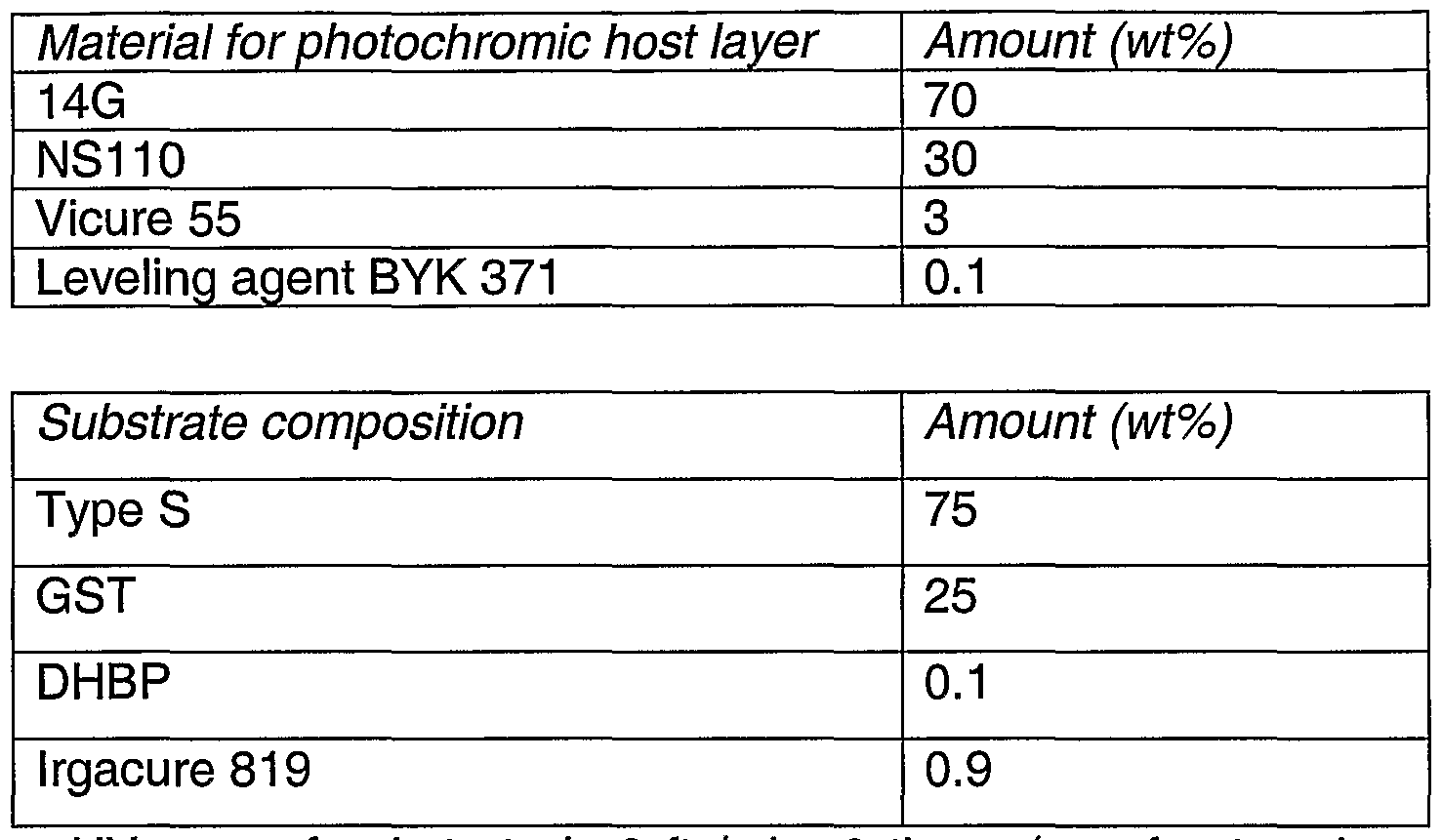
- Table 1 shows a typical formulation that is used in the method of the present invention to produce ophthalmic lenses.
- a solution of the formulation was stirred for about an hour to allow complete dissolution of all components before degassing under vacuum for 30 mins.
- the solution was spin-coated onto the casting face with spinning speed at approximately 870 rpm.
- the coated mould was then filled with the lens monomer composition and UV cured using two passes (one front and one back) at a line speed of 3.5 ft/min.
- the cured lenses were then imbibed for incorporation of photochromic compounds.
- the imbibition method was the same as that disclosed in United States patent 5,882,556.
- Table 2 shows the photopic intensity, t % (activation), the ty 2 (fade), t % (fade) which is the equilibrium intensity reached after 15 minutes of continuous radiation, the time for the photochromic compounds to reach 50% of equilibrium intensity, the time for the photochromic compounds to fade back to 50% of equilibrium intensity and the time for the photochromic compounds to fade back to 25% of equilibrium intensity, respectively. It can be seen that the times achieved with lenses formed using the method of the present invention are much shorter than for a commercially available lens (VelocityTM which is available from SOLA International Inc. and is a cast lens which is later imbibed after curing).
- VelocityTM which is available from SOLA International Inc. and is a cast lens which is later imbibed after curing.
- lens substrate in this example is hostile to photochromic compounds in that the polymer is highly cross linked which tends to slow down the activation and fading of the photochromic compound and it is also relatively high in sulphur which tends to degrade photochromic compounds.
- Host layer Spin speed 600 rpm, UV cure at 4.5 ft/min Substrate is cured: 3.5 ft/min 2 times (one front and one back) with a V lamp
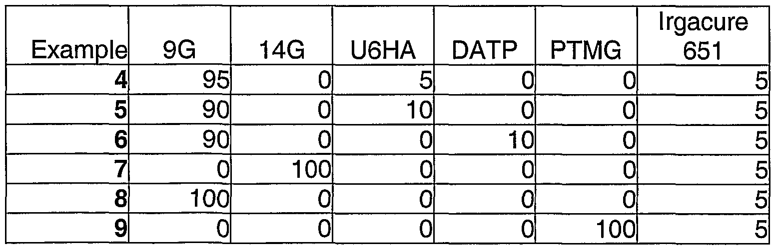
- Table 5 shows further formulations that were used in the process of the present invention.
- the quantities of material are given in wt% and the coatings were applied as for Example 1.
- Table 6 shows the results of the photochromic performance of the lenses of Examples 4 to 9.
- the steel wool abrasion test data refers to lenses that were coated with a standard siloxane hard coat and cured before abrasion testing.
- the nanoindentation depth of a coated lens provides an indication of the activation half life or the photochromic performance of a coated lens.
- a relatively non-rigid or 'soft' local environment in the photochromic host layer is thought to allow sufficient flexibility and room for the photochromic compound molecules to move into the activated state. This is thought to lead to an increase in photochromic performance.
- the Barcol hardness of monolithic lenses was correlated with the nanoindentation depth of the monolithic lenses.
- the Barcol hardness is a macro-indentation method that provides information about the softness of a lens at about 100 micron depth in the lens. In contrast, measurement of the nanoindentation depth is only sensitive to the top 1 to 20 microns of the lens.
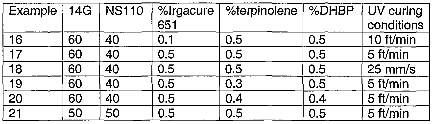
- the nanoindentation depth of lenses having the compositions shown in Table 7 was measured using a UMIS 2000 which is available through the Division of Applied Physics of CSIRO Australia. Different indenter tips may be used, but a half spherical tip of radius 5 micron was generally used. The experiments were performed using a force controlled method where the indentation curves as a function of applied force up to a determined maximum force (for example 10 mN) were studied.
- the nanoindentation depth, photochromic performance and abrasion resistance for the coated lenses are provided in Table 8.
- the abrasion resistance data shown in Table 8 refers to a lens that has been coated with a standard siloxane hard coat and cured prior to abrasion testing.
- Figure 1 shows the correlation between nanoindentation depth and darkening times.
- the optimal nanoindentation depth of a lens of the present invention may be between 9000 nm to 2500 nm.
- the nanoindentation depth may also give an indication of the abrasion resistance of a hard coated lens. It has been found that the abrasion resistance of a hard coated lens is dependent to some degree on the material onto which the hard coating is applied. Generally, the softer the photochromic host layer the poorer the abrasion resistance of the lens even after it has been over coated with a conventional hard coat.
- Dual cure coating requires the use of chain transfer agents which may be selected from mercaptans, allylics, styrene derivatives, terpinolene and mixtures thereof.
- the nanoindentation depths before and after imbibition are shown in Table 11.
- the imbibition conditions were 135-140 degrees Celsius for four hours.
- the gasket can then be filled with the substrate of choice.
- SpectraliteTM was used.
- the occurrence or extent of the breakthrough of substrate monomer into the photochromic host layer is dependent on the degree of cure of the host layer and the composition of the host layer. Generally, the harder the resultant host layer the less breakthrough occurs in the same amount of time.
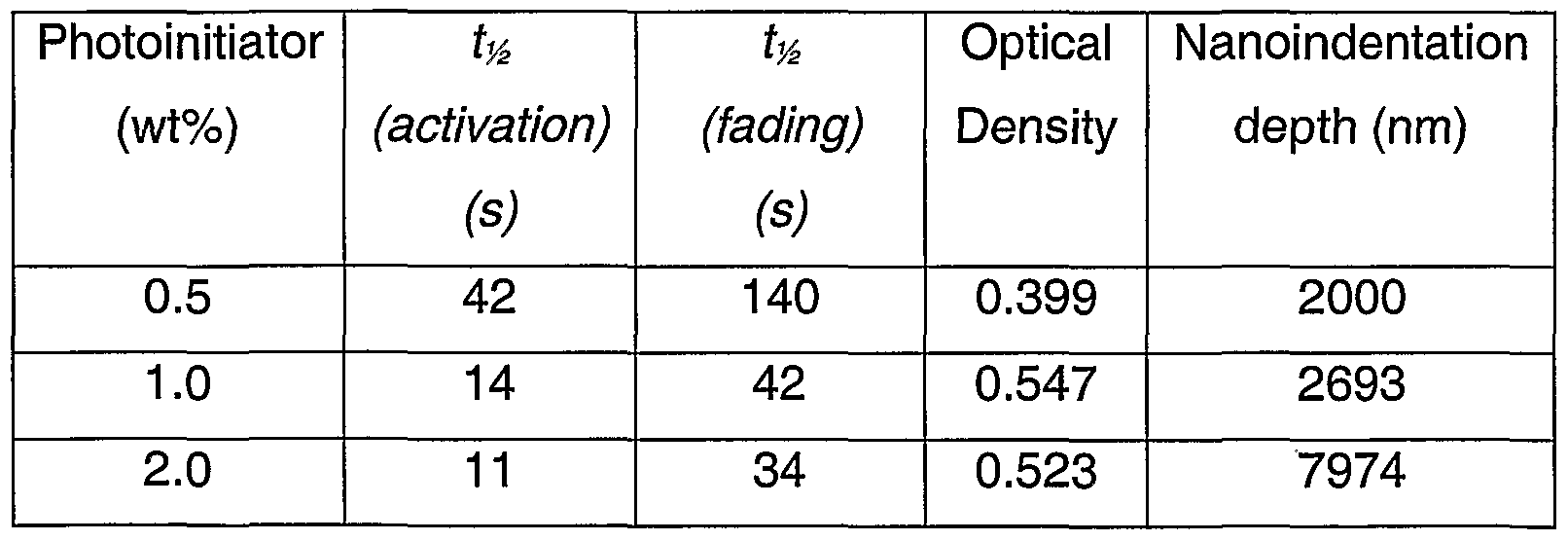
- Table 12 shows the effect of photoinitiator content on the nanoindentation depth and the photochromic performance of a 9G in-mould coated lens.
- a cast lens using 100% 9G is a very soft lens, whereas SpectraliteTM is reasonably hard and rigid by comparison; the nanoindentation depths are 15000 nm and 2000 nm, respectively.
- the host layer is better sealed with higher cure and the top layer of the lens becomes more like pure 9G, which has a darkening time of 9 seconds as a cast lens.
- the nanoindentation method can be used (1) as an indicator of whether the host layer had been breakthrough by the substrate monomers, and (2) to measure how soft the actual top layer of host layer is.
- Breakthrough of substrate monomer into the photochromic host layer causes an apparent decrease in the coating thickness which therefore decreases the volumetric environment for the photochromic compound. This leads to a harder coating and a decrease in the total amount of photochromic compound uptake.
- Table 12 also shows an increase in OD (optical density) when breakthrough is minimised by increasing the amount of photoinitiator in a lens made of 100% 9G monomer.
- MR-7 is a thermally cured substrate that is not imbibable.
- the MR-7 monomer is low viscosity and takes hours to reach gelation. Thus the time of contact for the photochromic host layer and the substrate monomer is very long and the time involved easily allows breakthrough to occur.
- MR-7 is used depending on the exact composition of the host layer, the resulting lens is either not imbibable or very slow due to breakthrough.
- Breakthrough can be overcome by using a barrier layer, which may be a highly crosslinked material or one sufficiently rigid to prevent penetration of the substrate monomer into the coating.
- Table 13 provides an example of a barrier layer.
- the procedure for applying the barrier layer was as follows. Initially the coating was UV cured (V-globe) @ 3ft/min. The barrier layer material was then applied on top of the photochromic host layer and subsequently UV-cured using the same conditions as the photochromic host layer cure.
- the substrate in this example was MR-7 which is a commercially available monomer with an index of 1.67.
- Table 14 provides details of another barrier layer composition. Table 14
- This particular barrier layer example is at stoichiometric ratio for the thiol and isocyanate. This can be altered to suit a particular requirement for the substrate. In some cases, it may be desirable to have a non-stoichiometric ratio so there is an excess of one component such that the reactive functional group may react with the substrate monomer. The percentage of the DBTC (catalyst) may also be changed as appropriate.
Abstract
Description


Claims
Priority Applications (7)
| Application Number | Priority Date | Filing Date | Title |
|---|---|---|---|
| AU2002366250A AU2002366250B2 (en) | 2001-12-14 | 2002-12-13 | Photochromic coating process |
| DE60229162T DE60229162D1 (en) | 2001-12-14 | 2002-12-13 | PHOTOCHROMIC COATING PROCESS |
| MXPA04005777A MXPA04005777A (en) | 2001-12-14 | 2002-12-13 | Photochromic coating process. |
| BRPI0214893-5A BR0214893B1 (en) | 2001-12-14 | 2002-12-13 | method for making a photochromic article, and photochromic article. |
| US10/498,744 US20050116381A1 (en) | 2001-12-14 | 2002-12-13 | Photochromic coating process |
| EP02804841A EP1453662B1 (en) | 2001-12-14 | 2002-12-13 | Photochromic coating process |
| US13/211,936 US9453950B2 (en) | 2001-12-14 | 2011-08-17 | Photochromic coating process |
Applications Claiming Priority (2)
| Application Number | Priority Date | Filing Date | Title |
|---|---|---|---|
| AUPR9492A AUPR949201A0 (en) | 2001-12-14 | 2001-12-14 | Photochromic coating process |
| AUPR9492 | 2001-12-14 |
Related Child Applications (3)
| Application Number | Title | Priority Date | Filing Date |
|---|---|---|---|
| US10/498,744 A-371-Of-International US20050116381A1 (en) | 2001-12-14 | 2002-12-13 | Photochromic coating process |
| US10498744 A-371-Of-International | 2002-12-13 | ||
| US13/211,936 Division US9453950B2 (en) | 2001-12-14 | 2011-08-17 | Photochromic coating process |
Publications (1)
| Publication Number | Publication Date |
|---|---|
| WO2003051615A1 true WO2003051615A1 (en) | 2003-06-26 |
Family
ID=3833108
Family Applications (1)
| Application Number | Title | Priority Date | Filing Date |
|---|---|---|---|
| PCT/AU2002/001691 WO2003051615A1 (en) | 2001-12-14 | 2002-12-13 | Photochromic coating process |
Country Status (9)
| Country | Link |
|---|---|
| US (2) | US20050116381A1 (en) |
| EP (1) | EP1453662B1 (en) |
| CN (1) | CN100425437C (en) |
| AT (1) | ATE409578T1 (en) |
| AU (1) | AUPR949201A0 (en) |
| BR (1) | BR0214893B1 (en) |
| DE (1) | DE60229162D1 (en) |
| MX (1) | MXPA04005777A (en) |
| WO (1) | WO2003051615A1 (en) |
Cited By (3)
| Publication number | Priority date | Publication date | Assignee | Title |
|---|---|---|---|---|
| DE102005022860A1 (en) * | 2005-05-18 | 2006-11-23 | Rodenstock Gmbh | Method for producing a photochromic plastic article |
| WO2007064565A1 (en) * | 2005-11-29 | 2007-06-07 | Bausch & Lomb Incorporated | Method for coating lens material |
| EP3542956A1 (en) | 2018-03-23 | 2019-09-25 | Carl Zeiss Vision International GmbH | Method for manufacturing spectacle lenses according to a prescription |
Families Citing this family (10)
| Publication number | Priority date | Publication date | Assignee | Title |
|---|---|---|---|---|
| WO2004078364A1 (en) * | 2003-03-05 | 2004-09-16 | Tokuyama Corporation | Method of manufacturing laminated body |
| US8550623B2 (en) * | 2005-03-01 | 2013-10-08 | Carl Zeiss Vision Australia Holdings, Ltd. | Coatings for ophthalmic lens elements |
| CN101466529B (en) * | 2006-05-09 | 2014-07-16 | 卡尔蔡司视觉澳大利亚控股有限公司 | Methods for forming coated high index optical elements |
| CN101512395B (en) * | 2006-06-30 | 2012-10-24 | Hoya株式会社 | Photochromic film, photochromic lens having the same, and process for producing photochromic lens |
| KR20090074019A (en) * | 2006-10-25 | 2009-07-03 | 미쓰비시 가가꾸 가부시키가이샤 | Volume hologram optical recording medium, composition for volume hologram recording layer formation, and volume hologram recording material |
| WO2010105289A1 (en) * | 2009-03-16 | 2010-09-23 | Carl Zeiss Vision Australia Holdings Limited | Liquid casting compositions, production processes and photochromic optical elements |
| DE102010044893A1 (en) * | 2010-03-10 | 2011-09-15 | Rodenstock Gmbh | New glass manufacturing process for plastic glasses |
| MX2013011788A (en) * | 2011-04-13 | 2014-03-26 | Tokuyama Corp | Photochromic composition. |
| US9733488B2 (en) | 2015-11-16 | 2017-08-15 | Younger Mfg. Co. | Composite constructed optical lens |
| EP3444290A1 (en) * | 2017-08-16 | 2019-02-20 | Covestro Deutschland AG | Indicator system |
Citations (6)
| Publication number | Priority date | Publication date | Assignee | Title |
|---|---|---|---|---|
| GB2096130A (en) * | 1981-04-08 | 1982-10-13 | Corning Glass Works | Photochromic glass suitable for microsheet and simultaneous heat treatment and shaping |
| WO1995015845A1 (en) * | 1993-12-10 | 1995-06-15 | Innotech, Inc. | Photochromic lenses and method for manufacturing |
| US5523030A (en) * | 1993-04-21 | 1996-06-04 | Sola International Inc. | Method of making a moulded photochromic lens |
| WO2001010635A2 (en) * | 1999-08-10 | 2001-02-15 | Giorgio Trani | Filmable material with characteristics selectively modifiable by administration of particular types of energy |
| WO2001021375A1 (en) * | 1999-09-21 | 2001-03-29 | Sola International Holdings Ltd | Method of forming a coated optical element |
| WO2001049478A2 (en) * | 1999-12-30 | 2001-07-12 | Bayer Corporation | A process for preparing a photochromic lens |
Family Cites Families (30)
| Publication number | Priority date | Publication date | Assignee | Title |
|---|---|---|---|---|
| US4043637A (en) * | 1973-06-15 | 1977-08-23 | American Optical Corporation | Photochromic light valve |
| US4544572A (en) * | 1982-09-07 | 1985-10-01 | Minnesota Mining And Manufacturing Company | Coated ophthalmic lenses and method for coating the same |
| US4774035A (en) * | 1986-01-14 | 1988-09-27 | Camelot Industries Corporation | Process of coating an ophthalmic lens |
| US4800123A (en) * | 1987-09-03 | 1989-01-24 | Freeman Chemical Corporation | In-mold scratch resistant coating for peroxide curable urethane elastomers |
| US5049321A (en) * | 1988-03-25 | 1991-09-17 | Signet Armorlite, Inc. | Method for forming coated plastic optical elements |
| US5880171A (en) * | 1989-05-01 | 1999-03-09 | 2C Optics, Inc. | Fast curing polymeric compositions for ophthalmic lenses and apparatus for preparing lenses |
| US5079319A (en) * | 1989-10-25 | 1992-01-07 | Ciba-Geigy Corporation | Reactive silicone and/or fluorine containing hydrophilic prepolymers and polymers thereof |
| US5306799A (en) | 1992-08-26 | 1994-04-26 | Mitsui Toatsu Chemicals, Inc. | High refractive index plastic lens and composition therefor |
| AU5111293A (en) | 1993-10-06 | 1995-05-01 | Cook Composites And Polymers Company, Inc. | Dual cure, in-mold process for manufacturing abrasion resistant, coated thermoplastic articles |
| US5531940A (en) * | 1993-12-10 | 1996-07-02 | Innotech, Inc. | Method for manufacturing photochromic lenses |
| US5608115A (en) * | 1994-01-26 | 1997-03-04 | Mitsui Toatsu Chemicals, Inc. | Polythiol useful for preparing sulfur-containing urethane-based resin and process for producing the same |
| AUPN007194A0 (en) * | 1994-12-16 | 1995-01-19 | Sola International Holdings Ltd | Method of preparing photochromic article |
| US7048997B2 (en) * | 1995-03-03 | 2006-05-23 | Vision-Ease Lens | Production of optical elements |
| US6313251B1 (en) * | 1995-05-30 | 2001-11-06 | Sola International Holdings, Ltd. | High index/high abbe number composition |
| DE69612195T3 (en) * | 1995-05-30 | 2006-07-06 | Sola International Holdings, Ltd., Lonsdale | COMPOSITION WITH HIGH INDEX AND HIGH ABBE NUMBER |
| US5807975A (en) * | 1995-08-16 | 1998-09-15 | Mitsubishi Gas Chemical Company,Inc. | Alkyl sulfide type episulfide compound |
| US5770115A (en) * | 1996-04-19 | 1998-06-23 | Ppg Industries, Inc. | Photochromic naphthopyran compositions of improved fatigue resistance |
| US5789015A (en) * | 1996-06-26 | 1998-08-04 | Innotech, Inc. | Impregnation of plastic substrates with photochromic additives |
| US5811503A (en) * | 1996-11-27 | 1998-09-22 | Ppg Industries, Inc. | Polymerizable composition |
| US5914174A (en) * | 1996-12-05 | 1999-06-22 | Innotech, Inc. | Lens or semi-finished blank comprising photochromic resin compositions |
| US6204311B1 (en) * | 1998-03-13 | 2001-03-20 | Mitsui Chemicals, Inc. | Polymerizable composition |
| BR9913869A (en) * | 1998-09-11 | 2004-12-28 | Ppg Ind Ohio Inc | Naphthoopyran Compound and Photochromic Articles |
| US6419873B1 (en) * | 1999-03-19 | 2002-07-16 | Q2100, Inc. | Plastic lens systems, compositions, and methods |
| WO2001002449A2 (en) * | 1999-07-02 | 2001-01-11 | Ppg Industries Ohio, Inc. | Poly(meth)acrylic photochromic coating |
| WO2001021325A1 (en) * | 1999-09-22 | 2001-03-29 | Flores Eustacio R Jr | Soap dispensing apparatus |
| AUPQ662300A0 (en) | 2000-03-31 | 2000-05-04 | Sola International Holdings Ltd | Photochromic article and method of preparation |
| DE60215168T2 (en) * | 2001-05-29 | 2007-08-23 | Essilor International Compagnie Générale d'Optique | METHOD FOR TRANSFERRING A HYDROPHOBIC COATING LAYER FROM A MOLDING TO AN OPTICAL SUBSTRATE |
| AUPR949001A0 (en) * | 2001-12-14 | 2002-01-24 | Sola International Holdings Ltd | Abrasion resistant coating composition |
| US7025458B2 (en) * | 2002-08-07 | 2006-04-11 | Vision-Ease Lens | Process to mold a plastic optical article with integrated hard coating |
| CN101466529B (en) * | 2006-05-09 | 2014-07-16 | 卡尔蔡司视觉澳大利亚控股有限公司 | Methods for forming coated high index optical elements |
-
2001
- 2001-12-14 AU AUPR9492A patent/AUPR949201A0/en not_active Abandoned
-
2002
- 2002-12-13 AT AT02804841T patent/ATE409578T1/en not_active IP Right Cessation
- 2002-12-13 EP EP02804841A patent/EP1453662B1/en not_active Expired - Lifetime
- 2002-12-13 MX MXPA04005777A patent/MXPA04005777A/en active IP Right Grant
- 2002-12-13 WO PCT/AU2002/001691 patent/WO2003051615A1/en active IP Right Grant
- 2002-12-13 US US10/498,744 patent/US20050116381A1/en not_active Abandoned
- 2002-12-13 CN CNB028249941A patent/CN100425437C/en not_active Expired - Lifetime
- 2002-12-13 BR BRPI0214893-5A patent/BR0214893B1/en active IP Right Grant
- 2002-12-13 DE DE60229162T patent/DE60229162D1/en not_active Expired - Lifetime
-
2011
- 2011-08-17 US US13/211,936 patent/US9453950B2/en active Active
Patent Citations (6)
| Publication number | Priority date | Publication date | Assignee | Title |
|---|---|---|---|---|
| GB2096130A (en) * | 1981-04-08 | 1982-10-13 | Corning Glass Works | Photochromic glass suitable for microsheet and simultaneous heat treatment and shaping |
| US5523030A (en) * | 1993-04-21 | 1996-06-04 | Sola International Inc. | Method of making a moulded photochromic lens |
| WO1995015845A1 (en) * | 1993-12-10 | 1995-06-15 | Innotech, Inc. | Photochromic lenses and method for manufacturing |
| WO2001010635A2 (en) * | 1999-08-10 | 2001-02-15 | Giorgio Trani | Filmable material with characteristics selectively modifiable by administration of particular types of energy |
| WO2001021375A1 (en) * | 1999-09-21 | 2001-03-29 | Sola International Holdings Ltd | Method of forming a coated optical element |
| WO2001049478A2 (en) * | 1999-12-30 | 2001-07-12 | Bayer Corporation | A process for preparing a photochromic lens |
Cited By (4)
| Publication number | Priority date | Publication date | Assignee | Title |
|---|---|---|---|---|
| DE102005022860A1 (en) * | 2005-05-18 | 2006-11-23 | Rodenstock Gmbh | Method for producing a photochromic plastic article |
| WO2007064565A1 (en) * | 2005-11-29 | 2007-06-07 | Bausch & Lomb Incorporated | Method for coating lens material |
| EP3542956A1 (en) | 2018-03-23 | 2019-09-25 | Carl Zeiss Vision International GmbH | Method for manufacturing spectacle lenses according to a prescription |
| WO2019179660A1 (en) | 2018-03-23 | 2019-09-26 | Carl Zeiss Vision International Gmbh | Method for manufacturing spectacle lenses according to a prescription |
Also Published As
| Publication number | Publication date |
|---|---|
| DE60229162D1 (en) | 2008-11-13 |
| BR0214893B1 (en) | 2011-11-29 |
| EP1453662A1 (en) | 2004-09-08 |
| MXPA04005777A (en) | 2004-09-10 |
| BR0214893A (en) | 2004-12-07 |
| US9453950B2 (en) | 2016-09-27 |
| CN1604841A (en) | 2005-04-06 |
| ATE409578T1 (en) | 2008-10-15 |
| US20120037859A1 (en) | 2012-02-16 |
| EP1453662A4 (en) | 2005-06-01 |
| US20050116381A1 (en) | 2005-06-02 |
| EP1453662B1 (en) | 2008-10-01 |
| AU2002366250A1 (en) | 2003-06-30 |
| AUPR949201A0 (en) | 2002-01-24 |
| CN100425437C (en) | 2008-10-15 |
Similar Documents
| Publication | Publication Date | Title |
|---|---|---|
| US9453950B2 (en) | Photochromic coating process | |
| US7560056B2 (en) | Photochromic contact lenses and methods of manufacturing | |
| US20050258408A1 (en) | Photochromic contact lenses and methods for their production | |
| AU762653B2 (en) | Method for preparing a latex with photochromic properties and uses thereof, particularly in ophthalmology | |
| JP2004536933A (en) | High refractive index optical resin composition | |
| EP2408824B1 (en) | Liquid casting compositions, production processes and photochromic optical elements | |
| EP0842236A1 (en) | Photochromic polymer | |
| WO1999038924A1 (en) | Coating composition | |
| AU688653B2 (en) | Incorporating photochromic molecules in light transmissible articles | |
| JP2001514677A (en) | Crosslinkable polymerizable composition | |
| US8044141B2 (en) | Tinting optical substrates | |
| AU2017287530A1 (en) | Spectacle lens and spectacles | |
| AU2017287528B2 (en) | Method for manufacturing spectacle lens | |
| US20080224338A1 (en) | Method for producing a photochromic plastic article | |
| AU2002366250B2 (en) | Photochromic coating process | |
| JP2012173675A (en) | Method for manufacturing lens | |
| JP2022166771A (en) | Photochromic optical article, and manufacturing method therefor | |
| JP2017058611A (en) | Optical product including photochromic layer | |
| AU728612B2 (en) | Process for preparing optical articles |
Legal Events
| Date | Code | Title | Description |
|---|---|---|---|
| AK | Designated states |
Kind code of ref document: A1 Designated state(s): AE AG AL AM AT AU AZ BA BB BG BR BY BZ CA CH CN CO CR CU CZ DE DK DM DZ EC EE ES FI GB GD GE GH GM HR HU ID IL IN IS JP KE KG KP KR KZ LC LK LR LS LT LU LV MA MD MG MK MN MW MX MZ NO NZ OM PH PL PT RO RU SC SD SE SG SK SL TJ TM TN TR TT TZ UA UG US UZ VC VN YU ZA ZM ZW |
|
| AL | Designated countries for regional patents |
Kind code of ref document: A1 Designated state(s): GH GM KE LS MW MZ SD SL SZ TZ UG ZM ZW AM AZ BY KG KZ MD RU TJ TM AT BE BG CH CY CZ DE DK EE ES FI FR GB GR IE IT LU MC NL PT SE SI SK TR BF BJ CF CG CI CM GA GN GQ GW ML MR NE SN TD TG |
|
| DFPE | Request for preliminary examination filed prior to expiration of 19th month from priority date (pct application filed before 20040101) | ||
| 121 | Ep: the epo has been informed by wipo that ep was designated in this application | ||
| WWE | Wipo information: entry into national phase |
Ref document number: 2002366250 Country of ref document: AU |
|
| WWE | Wipo information: entry into national phase |
Ref document number: 2002804841 Country of ref document: EP |
|
| WWE | Wipo information: entry into national phase |
Ref document number: PA/a/2004/005777 Country of ref document: MX Ref document number: 20028249941 Country of ref document: CN |
|
| WWP | Wipo information: published in national office |
Ref document number: 2002804841 Country of ref document: EP |
|
| WWE | Wipo information: entry into national phase |
Ref document number: 10498744 Country of ref document: US |
|
| NENP | Non-entry into the national phase |
Ref country code: JP |
|
| WWW | Wipo information: withdrawn in national office |
Ref document number: JP |
|
| WWG | Wipo information: grant in national office |
Ref document number: 2002366250 Country of ref document: AU |
|
| WWG | Wipo information: grant in national office |
Ref document number: 2002804841 Country of ref document: EP |