WO2002095982A1 - Communication system and method using transmit diversity - Google Patents

Communication system and method using transmit diversity Download PDF

Info

Publication number
WO2002095982A1
WO2002095982A1 PCT/EP2001/005833 EP0105833W WO02095982A1 WO 2002095982 A1 WO2002095982 A1 WO 2002095982A1 EP 0105833 W EP0105833 W EP 0105833W WO 02095982 A1 WO02095982 A1 WO 02095982A1
Authority
WO
WIPO (PCT)
Prior art keywords
feedback
receiving device
transmitting
transmitting device
accordance
Prior art date
Application number
PCT/EP2001/005833
Other languages
French (fr)
Inventor
Jyri Hämäläinen
Risto Wichman
Original Assignee
Nokia Corporation
Priority date (The priority date is an assumption and is not a legal conclusion. Google has not performed a legal analysis and makes no representation as to the accuracy of the date listed.)
Filing date
Publication date
Application filed by Nokia Corporation filed Critical Nokia Corporation
Priority to PCT/EP2001/005833 priority Critical patent/WO2002095982A1/en
Priority to EP01951511A priority patent/EP1389367A1/en
Priority to US10/478,242 priority patent/US7224943B2/en
Publication of WO2002095982A1 publication Critical patent/WO2002095982A1/en
Priority to US11/367,447 priority patent/US7643799B2/en
Priority to US11/367,448 priority patent/US7599666B2/en

Links

Classifications

    • HELECTRICITY
    • H04ELECTRIC COMMUNICATION TECHNIQUE
    • H04BTRANSMISSION
    • H04B7/00Radio transmission systems, i.e. using radiation field
    • H04B7/02Diversity systems; Multi-antenna system, i.e. transmission or reception using multiple antennas
    • H04B7/04Diversity systems; Multi-antenna system, i.e. transmission or reception using multiple antennas using two or more spaced independent antennas
    • H04B7/06Diversity systems; Multi-antenna system, i.e. transmission or reception using multiple antennas using two or more spaced independent antennas at the transmitting station
    • H04B7/0613Diversity systems; Multi-antenna system, i.e. transmission or reception using multiple antennas using two or more spaced independent antennas at the transmitting station using simultaneous transmission
    • H04B7/0615Diversity systems; Multi-antenna system, i.e. transmission or reception using multiple antennas using two or more spaced independent antennas at the transmitting station using simultaneous transmission of weighted versions of same signal
    • H04B7/0619Diversity systems; Multi-antenna system, i.e. transmission or reception using multiple antennas using two or more spaced independent antennas at the transmitting station using simultaneous transmission of weighted versions of same signal using feedback from receiving side
    • H04B7/0621Feedback content
    • H04B7/0634Antenna weights or vector/matrix coefficients
    • HELECTRICITY
    • H04ELECTRIC COMMUNICATION TECHNIQUE
    • H04BTRANSMISSION
    • H04B7/00Radio transmission systems, i.e. using radiation field
    • H04B7/02Diversity systems; Multi-antenna system, i.e. transmission or reception using multiple antennas
    • H04B7/04Diversity systems; Multi-antenna system, i.e. transmission or reception using multiple antennas using two or more spaced independent antennas
    • H04B7/06Diversity systems; Multi-antenna system, i.e. transmission or reception using multiple antennas using two or more spaced independent antennas at the transmitting station
    • H04B7/0613Diversity systems; Multi-antenna system, i.e. transmission or reception using multiple antennas using two or more spaced independent antennas at the transmitting station using simultaneous transmission
    • H04B7/0615Diversity systems; Multi-antenna system, i.e. transmission or reception using multiple antennas using two or more spaced independent antennas at the transmitting station using simultaneous transmission of weighted versions of same signal
    • H04B7/0619Diversity systems; Multi-antenna system, i.e. transmission or reception using multiple antennas using two or more spaced independent antennas at the transmitting station using simultaneous transmission of weighted versions of same signal using feedback from receiving side
    • H04B7/0636Feedback format
    • H04B7/0645Variable feedback
    • H04B7/065Variable contents, e.g. long-term or short-short
    • HELECTRICITY
    • H04ELECTRIC COMMUNICATION TECHNIQUE
    • H04BTRANSMISSION
    • H04B7/00Radio transmission systems, i.e. using radiation field
    • H04B7/02Diversity systems; Multi-antenna system, i.e. transmission or reception using multiple antennas
    • H04B7/04Diversity systems; Multi-antenna system, i.e. transmission or reception using multiple antennas using two or more spaced independent antennas
    • H04B7/06Diversity systems; Multi-antenna system, i.e. transmission or reception using multiple antennas using two or more spaced independent antennas at the transmitting station
    • H04B7/0613Diversity systems; Multi-antenna system, i.e. transmission or reception using multiple antennas using two or more spaced independent antennas at the transmitting station using simultaneous transmission
    • H04B7/0615Diversity systems; Multi-antenna system, i.e. transmission or reception using multiple antennas using two or more spaced independent antennas at the transmitting station using simultaneous transmission of weighted versions of same signal
    • H04B7/0619Diversity systems; Multi-antenna system, i.e. transmission or reception using multiple antennas using two or more spaced independent antennas at the transmitting station using simultaneous transmission of weighted versions of same signal using feedback from receiving side
    • H04B7/0652Feedback error handling
    • H04B7/0656Feedback error handling at the transmitter, e.g. error detection at base station
    • HELECTRICITY
    • H04ELECTRIC COMMUNICATION TECHNIQUE
    • H04BTRANSMISSION
    • H04B7/00Radio transmission systems, i.e. using radiation field
    • H04B7/02Diversity systems; Multi-antenna system, i.e. transmission or reception using multiple antennas
    • H04B7/04Diversity systems; Multi-antenna system, i.e. transmission or reception using multiple antennas using two or more spaced independent antennas
    • H04B7/08Diversity systems; Multi-antenna system, i.e. transmission or reception using multiple antennas using two or more spaced independent antennas at the receiving station
    • H04B7/0837Diversity systems; Multi-antenna system, i.e. transmission or reception using multiple antennas using two or more spaced independent antennas at the receiving station using pre-detection combining
    • H04B7/0842Weighted combining
    • H04B7/0848Joint weighting
    • H04B7/0854Joint weighting using error minimizing algorithms, e.g. minimum mean squared error [MMSE], "cross-correlation" or matrix inversion
    • HELECTRICITY
    • H04ELECTRIC COMMUNICATION TECHNIQUE
    • H04BTRANSMISSION
    • H04B7/00Radio transmission systems, i.e. using radiation field
    • H04B7/02Diversity systems; Multi-antenna system, i.e. transmission or reception using multiple antennas
    • H04B7/04Diversity systems; Multi-antenna system, i.e. transmission or reception using multiple antennas using two or more spaced independent antennas
    • H04B7/08Diversity systems; Multi-antenna system, i.e. transmission or reception using multiple antennas using two or more spaced independent antennas at the receiving station
    • H04B7/0837Diversity systems; Multi-antenna system, i.e. transmission or reception using multiple antennas using two or more spaced independent antennas at the receiving station using pre-detection combining
    • H04B7/0842Weighted combining
    • H04B7/0862Weighted combining receiver computing weights based on information from the transmitter

Definitions

  • the present invention relates to a method and a system for influencing signals transmitted from a transmitting device to a receiving device.
  • Transmit diversity techniques provide attractive solutions for increasing downlink capacity in 3G (Third Generation) communication systems within low-mobility environments.
  • the complexity to implement transmit diversity mainly burdens the base station making the technique more suitable for low-cost handsets than, e.g., receive diversity.
  • Open-loop and closed- loop transmit diversity techniques have been already standardized and improvements are being developed constantly with 3GPP (Third Generation Partnership) WCDMA (Wideband Code Division Multiple Access) FDD (Frequency Division Duplex) and TDD (Time Division Duplex) modes, and transmit diversity is considered with EDGE (Enhanced Data rates for GSM Evolution) standardization as well.
  • WCDMA Wideband Code Division Multiple Access
  • FDD Frequency Division Duplex
  • TDD Time Division Duplex
  • closed-loop transmit two of the critical phenomena that may change the performance of the closed-loop schemes are the temporal correlation corresponding to each antenna separately and the spatial correlation between the antennas.
  • the first one of these phenomena is critical when mobile is moving and/or a feedback word is long.
  • the second phenomenon is affecting usually slower or there might even be static correlations between antennas.
  • K "1 is inverse or pseudo inverse of K.
  • a channel covariance matrix can be calculated using a subset of channel paths. Since the feedback capacity is limited, we must choose a quantized set of feedback vectors w and design algorithms that provide best possible choice of w among all quantized weights. The standard describes two feedback modes where the first mode adjusts phases only and the second one adjusts transmit power as well [1]. Moreover, selection and/or phase adjustment algorithms have been proposed in [2]. The algorithms are based only on the fast feedback and they do not take into account the spatio-temporal properties of the channel. Furthermore, the quantization sets have been fixed in all previous concepts and specific values of weights have been chosen beforehand to be the same in all environments.
  • Siemens proposed an elaborateeigenbeamformer" approach [3] where MS (Mobile Station) measures R and signals a subset of eigenvectors to the BS (Base Station) , which are subsequently used for transmission.
  • the idea is to reduce dimension so that, for example, in the case of 4 Tx (Transmit) antennas the MS needs to monitor only two beams and consequently feedback signaling works with higher mobile speeds than in the case when the mobile station continuously updates weights of the 4 transmit antennas.
  • the SNR Signal to Noise Ratio
  • C is the ordered covariance matrix that takes into account the correlation between amplitudes and phases. (Note that C and R are different.)
  • C is an example of an ordered and phase adjusted channel matrix. It is found that the elements of C are the following
  • N is the number of phase adjustment feedback bits per antenna. If there is no spatial correlation between antennas, then the above expectations can be computed analytically and thus, weight vector u can be chosen beforehand since it is the eigenvector corresponding to the largest eigenvalue of C.
  • the adjustment algorithm is then such that the mobile station estimates the channel from M antennas and orders the samples according to magnitude.
  • the mobile station can either store the whole order information or only part of it.
  • Relative phases of the signals (not necessarily all phases; this depends on the specific algorithm) are then adjusted, i.e. the mobile station searches through possible adjustment combinations applying some algorithm and then chooses the best combination.
  • Both the order and phase adjustment information is then sent to the transmitter in the base station.
  • the transmitter selects antenna weights w based on the feedback information.
  • the phases are obtained directly from the FB (Feed Back) information and magnitudes of weights are selected using quantization based on (1) and (2) when order information is known. This requires in total log2(M!) +
  • Suboptimal FB weights requiring less FB bits can be determined using similar procedure as proposed in [4] . For example, if all antennas but the strongest one have the same Tx amplitude weight then only log2 (M) + (M-l)N FB bits are required.
  • the present invention provides a receiving device (e.g. a user equipment such as a mobile station) having a function to calculate a feedback signal to be sent to the assigned transmitting device of the Radio Access Network (RAN) such as RNC or BSS, for improved reception by the receiving device.
  • a receiving device e.g. a user equipment such as a mobile station
  • RNC Radio Access Network
  • BSS Radio Access Network
  • the present invention provides a transmitting device (e.g. RNC, BSS) having a function to determine transmit weights for transmission signals to be sent to the assigned receiving device such as a mobile station, for improved reception by the receiving device.
  • a transmitting device e.g. RNC, BSS
  • the assigned receiving device such as a mobile station
  • adaptive algorithms for calculating transmit weights are described. Due to the adaptive nature, the application domain of the closed loop transmit diversity algorithms is enlarged. Moreover, endless quarrels about transmit diversity modes can be terminated because, according to the present invention, no fixed transmit weight combination is specified. Beamforming solutions are typically based on a channel covariance matrix R. Thus, beamforming assumes correlation between the transmit antennas, and therefore it does not give good results in all environments.
  • the adaptive transmit diversity algorithm is based on real ordered covariance matrix C which does not contain any directional information. Instead, the directional information is provided by the short term feedback, i.e., phase adjustment.
  • An embodiment of the present invention describes adaptive weight generation for closed loop transmit diversity schemes in general for any kind of channel environment. Moreover, the goal of this embodiment is to propose a principle (not just a specific algorithm) where amplitude weights are generated by using low-pass filtering in a certain manner so that the main point is not the generation of the feedback signal, i.e. order and phase information, but determining transmit weights corresponding to some feedback signal format. These weights are generated and used in BS (no feedback from MS) or generated in MS and signaled to BS (note that this long-term feedback is different from the one in the 3GPP contribution
  • the transmit weights MS may also signal the elements of the ordered covariance matrix to BS.
  • the transmit weights BS may use these elements.
  • amplitude or transmit weights correspond to correlation of transmit antennas or transmit elements.
  • a mechanism is disclosed by which different diversity schemes can be turned on and off according to properties of the physical connection. It is known that there are several parameters that affect to the performance of different open and closed loop diversity algorithms. For example, the affect of mobile speed becomes crucial when more than two antenna closed-loop diversity schemes are used. Therefore, it is described to apply different algorithms for channels having different time correlation properties. Instead of measuring the time correlation of the channel in MS it is proposed that the measure for time correlation is computed by using the already existing feedback bits m BS . This is done by a simple filtering.
  • the two key ideas of this embodiment are the dynamic use of different diversity schemes (open or closed-loop) and the use of already existing feedback information in BS in order to choose the most suitable diversity scheme.
  • adaptive weight generation and transmit weight determination corresponding to some feedback signal format is enabled.
  • the adaptation may be done based on measurements from uplink, or by long-term feedback from the MS. Also, long term properties of the channel can be taken into account without communicating eigenvectors from the MS to the BS .
  • different feedback schemes are applied to the measured channels and the best scheme is chosen based on maximizing the largest eigenvalue of the ordered covariance matrix.
  • Fig. 1 shows transmit weights and SNR improvement obtained in flat Rayleigh fading channels as a function of antenna correlation when four transmit antennas are applied.
  • Fig. 2 shows transmit weights and SNR improvement obtained in flat Rayleigh fading channels as a function of spatial distance between antenna elements when four transmit antennas are applied.
  • Fig. 3 shows transmit weights and SNR improvement as a function of channel profiles when four transmit antennas are applied.
  • the above-described prior art approach is modified such that it adapts to the long-term environment.
  • a more general form is given to the ordered covariance matrix C and the corresponding quadratic form is defined in accordance with:
  • phase adjustments have already been done.
  • gain adjustment can be done before phase adjustment, or phase and gain adjustments can be made jointly in order to maximize the gain.
  • ordered covariance matrix C can be interpreted in a more general manner as R according to the prior art.
  • C can be measured using low-pass filtering or any adaptive algorithm in the same way as is conventionally done when determining R.
  • C can be measured either in BS or MS and unlike in the case of R (beamforming) a calibration of the antenna array is not required in the BS.
  • MS can only signal ordering and phase adjustment information and the whole signalling overhead for communicating eigenvectors (which has to be done in [3]) is avoided.
  • the pilot signal in FDD WCDMA uplink is power controlled while the common pilot channel in downlink is not, it does not affect the long-term statistics of C.
  • the angular spread in the BS is typically different from the one in MS.
  • the difference BS may apply some transform to the received signals, e.g. beamforming or independent component analysis, before calculating C.
  • the channel can be a subject to some transform in the mobile station or in the base station, like downlink beamforming, eigenbeamforming [3] or channel equalizing.
  • solid and dashed lines refer to SNR with and without feedback, respectively. It is noticed that weights are robust to spatial correlation.
  • SNR improvement converges to that of beamforming when antenna correlation is increasing.
  • the transmit weights are robust to different fading channels, the diversity gain is inversely proportional to the spatial correlation.
  • the BS may measure R as well and then, for example, introduce a small frequency offset in order to decrease spatial correlation. This should not affect C so that the BS and MS still agree from the Tx weights.
  • the feedback channel is subject to errors so that the gain and transmit weights obtained from equation (3) may not correspond to the actual situation.
  • the network may use some nominal feedback error probability and its probability density function, and signal it to the MS, or BS can estimate the quality of the feedback channel and send the information to MS. MS or BS can then simulate FB errors when calculating transmit weights.
  • Equation (3) attempts to combine coherently all M signals. However, it is also possible to apply the same concept when the transmit antennas are divided into groups which are combined incoherently. This corresponds to soft handover in WCDMA, or when some open loop transmit diversity is applied together with the feedback. Equation (3) becomes
  • ui may be different or same.
  • g ⁇ . h 2 k x and k is a priori or estimated transmit amplitude of the pilot signal from antenna i.
  • the integration times of the channel estimates can be set in such a way that the SIR in the output of the channel estimates becomes equal.
  • time delays r,associated to the channel estimates are different.
  • C is then estimated in such a way that all combinations of delays ⁇ , - ⁇ ,i ⁇ j between the channel estimates appear at an equal number of times when calculating the estimate.
  • antenna 1 If antenna 1 is best then its phase is adjusted against antenna 2. Other antennas are shut down.
  • antenna 2 If antenna 2 is best then its phase is adjusted against antenna 1. Other antennas are shut down.
  • Weight vectors u,,u 2 ,u,,u 4 are related to these four cases. They are eigenvectors corresponding to largest eigenvalues of 2x2 ordered covariance matrices C,,C 2 ,C 3 ,C 4 . In order to give these covariance matrices we write
  • an idea is to control the length of the feedback word in order to avoid the situation where channel changes remarkable during the feedback delay.
  • the change of the feedback word is done in the following way: firstly, the feedback mode is designed such that the feedback word corresponding to the scheme is built up from several shorter feedback words. That is, the feedback word is built up from smaller building blocks for example as follows
  • an FB word can be 2, 4 or 8 bits long and its structure is hierarchical in the sense that if the channel remains constant or almost constant during the feedback delay, then performance is improving when the FB word is becoming longer.
  • feedback words of different lengths can be used based on the temporal properties of the channel. If the channel is changing very slowly (i.e., the mobile is moving slowly) then the longest available word can be used, and when the changes of the channel become more rapid then shorter and shorter words are applied. In the above example, there are three alternatives for the FB word.
  • the length of FB word can be decided, for example, using the following schemes:
  • the present feedback scheme can be kept or the feedback word can even be enlarged.
  • the FB word BS may also choose to collect more than one consecutive feedback signals and process them jointly in order to diminish the effect of feedback errors.
  • FB control information is transmitted either from mobile to BS or vice versa.
  • some of the available capacity needs to be allocated for that purpose.
  • the update rate of this control information can be several frames since temporal properties of the channel are not changing rapidly and only few bits of control information is needed.
  • the FB word corresponding to this scheme can be of length 2, 4 or even 8 bits.
  • Each new stage is based on the previous stage.
  • Stage 1 (Length of the FB word is 2 bits) This stage uses two feedback bits in order to find the best channel in terms of power among the 4 possible alternatives.
  • Stage 2 (Length of the FB word is 4 bits) Now we use first stage 1. That is, we first decide which antenna is best in terms of gain and define first 2 FB bits. Then we choose some antenna (known for both transmitter and receiver; for example, if antenna 1 is best, then the chosen antenna is antenna 2, etc.) and adjust the relative phases between these two antennas. Third and fourth FB bits are now defined. It should be noticed that since the transmitter knows which antenna is the best one (in terms of gains) , antenna weights can be applied given in a manner that is explained in accordance with the first embodiment.
  • Stage 3 (Length of the FB word is 8 bits) Now we use first stage 2. Then we choose some third antenna (known for both transmitter and receiver) and adjust the relative phase between first two antennas and third antenna. This gives us fifth and sixth FB bits. Again antenna weights are changed in the transmitter. The final two FB bits are used in order to adjust the relative phase between the last antenna and three already adjusted antennas. Antenna weights are updated in each step.
  • Full order information requires log2(M!) FB bits, but it is possible to apply feedback refinement to transmit powers analogous to FDD WCDMA mode 1 which applies the refinement to phases. That is, during each slot only partial information is signalled, e.g. slot i tells whether antenna 1 is stronger than antenna 2, slot i+1 tells if antenna 3 is stronger than antenna 4, slot i+2 if antenna 2 is stronger than antenna 3, etc. Alternatively, only the strongest antenna can be signaled from MS to BS, and the BS maintains the ordered list of the antenna gains. Whenever new order information arrives, the list is updated so that, for example, the previous strongest antenna is moved to the second strongest position in the list. In general, the partial feedback can obey round robin signaling, where slot i tells the strongest antenna, next slot tells the second strongest antenna, etc., and BS maintais ordered list of the antenna gains. Modification to spatial adaptation
  • multiple feedback words of different lengths are calculated and applied to the received signal after an appropriate delay.
  • the calculation can be performed in MS or BS, and it maps the mobile speed directly to the expected gain of a closed loop mode. This is different from the typical Doppler shift estimation which is an indirect measure and may not provide appropriate information for switching between different closed loop modes. For example, when the correlation between transmit antennas is large, phase differences between the antennas as a function of mobile speed do not experience as rapid fluctuations as in the case of uncorrelated transmit antennas.
  • the procedure is similar to setting SIR target in outer loop power control, i.e.
  • gain estimation in BS may utilize additional information obtained from the received power control commands to increase the reliability of the mode switching by, for example, shortening the feedback word if the transmitted power shows an increasing trend.
  • 3GPP RAN WG1 performance results of basis selection transmit diversity for 4 antennas", Rl-00-1073
  • 3GPP RAN WG1 participated in 3GPP RAN WG1 : performance results of basis selection transmit diversity for 4 antennas", Rl-00-1073

Abstract

Influencing the transmission of signals from a transmitting device to a receiving device in a communication system comprising at least one transmitting device and at least one receiving device is disclosed. In a receiving station received transmission signals are processed and a feedback signal to be transmitted to a transmitting device is generated on the basis of the processed signals. Then, transmit weights to be applied to transmission signals are determined in accordance with the feedback signal.

Description

TITLE OF THE INVENTION
Communication System and Method using Transmit Diversity
FIELD OF THE INVENTION
The present invention relates to a method and a system for influencing signals transmitted from a transmitting device to a receiving device.
BACKGROUND OF THE INVENTION
Transmit diversity techniques provide attractive solutions for increasing downlink capacity in 3G (Third Generation) communication systems within low-mobility environments. The complexity to implement transmit diversity mainly burdens the base station making the technique more suitable for low-cost handsets than, e.g., receive diversity. Open-loop and closed- loop transmit diversity techniques have been already standardized and improvements are being developed constantly with 3GPP (Third Generation Partnership) WCDMA (Wideband Code Division Multiple Access) FDD (Frequency Division Duplex) and TDD (Time Division Duplex) modes, and transmit diversity is considered with EDGE (Enhanced Data rates for GSM Evolution) standardization as well.
In closed-loop transmit: diversity techniques two of the critical phenomena that may change the performance of the closed-loop schemes are the temporal correlation corresponding to each antenna separately and the spatial correlation between the antennas. The first one of these phenomena is critical when mobile is moving and/or a feedback word is long. The second phenomenon is affecting usually slower or there might even be static correlations between antennas. However, it is not realistic to assume that the spatial correlation properties remain the same in all environments. Therefore it is of great interest to search schemes that are able to adapt to the characteristics of the fading channel.
When there are several antenna elements in a transmitter antenna array, it is useful to design feedback modes (as mode 1 and mode 2 in FDD WCDMA) by which the downlink capacity can be increased. The conventional design criteria for these modes is based on the channel covariance matrix R given by
R = HWH, H=(h,,h2, ,hM), K = ( 2' X, )' .
where M is the number of transmit antennas, L is the number of channel paths and hm l s the complex channel coefficient corresponding to /th path of the channel between antenna m and mobile. The problem is to find antenna weight vector w = (w!,vi'2, ,xΛ/)' such that
Figure imgf000003_0001
is maximized. Another common approach is to choose such that
w"R wwKw
where K refers to the covariance of the noise and interference, is maximized. Alternatively, the generalized eigenvalue problem can be expressed to maximize
"H"K Ηw
where K"1 is inverse or pseudo inverse of K. Furthermore, a channel covariance matrix can be calculated using a subset of channel paths. Since the feedback capacity is limited, we must choose a quantized set of feedback vectors w and design algorithms that provide best possible choice of w among all quantized weights. The standard describes two feedback modes where the first mode adjusts phases only and the second one adjusts transmit power as well [1]. Moreover, selection and/or phase adjustment algorithms have been proposed in [2]. The algorithms are based only on the fast feedback and they do not take into account the spatio-temporal properties of the channel. Furthermore, the quantization sets have been fixed in all previous concepts and specific values of weights have been chosen beforehand to be the same in all environments.
Recently, Siemens proposed an „eigenbeamformer" approach [3] where MS (Mobile Station) measures R and signals a subset of eigenvectors to the BS (Base Station) , which are subsequently used for transmission. The idea is to reduce dimension so that, for example, in the case of 4 Tx (Transmit) antennas the MS needs to monitor only two beams and consequently feedback signaling works with higher mobile speeds than in the case when the mobile station continuously updates weights of the 4 transmit antennas. However, if there is no spatial correlation between the antennas the SNR (Signal to Noise Ratio) improvement becomes the same as with 2 Tx antennas. Furthermore, Siemens remarks that it is not necessary to calibrate the antennas when beamforming is based on the feedback from mobile to base.
For a moment it is assumed that we have a single path Rayleigh fading channel, M uncorrelated transmit antennas and relative phases of signals from different antennas have been adjusted by applying an algorithm given in [4]. That is, some or all signals from the different antennas are ranked and each phase is independently adjusted against the phase of the reference channel or antenna. Moreover, assume that the channel coefficients have been ordered with respect to their amplitudes c =\ hm \ into a descending order. Using the brackets in subindices denotes the given order. Then the expected SNR is given by:
Figure imgf000005_0001
Figure imgf000005_0003
where components of the weight vector u are now real and non- negative. Here C is the ordered covariance matrix that takes into account the correlation between amplitudes and phases. (Note that C and R are different.) C is an example of an ordered and phase adjusted channel matrix. It is found that the elements of C are the following
(2 ) cm m = E{a ,t) }, cm ] = cA,£{α(/B)α(l) } , " .k = cN 2 E{a(m)ak)} , m ≠ k
Figure imgf000005_0002
Here N is the number of phase adjustment feedback bits per antenna. If there is no spatial correlation between antennas, then the above expectations can be computed analytically and thus, weight vector u can be chosen beforehand since it is the eigenvector corresponding to the largest eigenvalue of C. The adjustment algorithm is then such that the mobile station estimates the channel from M antennas and orders the samples according to magnitude. The mobile station can either store the whole order information or only part of it. Relative phases of the signals (not necessarily all phases; this depends on the specific algorithm) are then adjusted, i.e. the mobile station searches through possible adjustment combinations applying some algorithm and then chooses the best combination. Both the order and phase adjustment information is then sent to the transmitter in the base station. The transmitter selects antenna weights w based on the feedback information. The phases are obtained directly from the FB (Feed Back) information and magnitudes of weights are selected using quantization based on (1) and (2) when order information is known. This requires in total log2(M!) +
(M-l)N FB bits (M! is the number of permutations of {αm}^=1 , and N is the number of phase bits/antenna) , and the SNR improvement is very close to the theoretical maximum, for example SNR= 3.8 in the case of M=4 Tx antennas and N=3 phase adjustment bits/antenna. Suboptimal FB weights requiring less FB bits can be determined using similar procedure as proposed in [4] . For example, if all antennas but the strongest one have the same Tx amplitude weight then only log2 (M) + (M-l)N FB bits are required.
However, there are some basic restrictions in the above procedure. Channels can attain multipath structure, fading statistics can be due to Rice, Rayleigh, Nagakami statistics or something else, and antennas can be spatially correlated. Moreover, the nature of all these phenomena can change when mobile is moving. Therefore, it is not always practical to fix the same weight magnitude quantization beforehand as it has been done in the above theoretical consideration, and as has been specified in Tx diversity mode 2 of FDD WCDMA.
SUMMARY OF THE INVENTION
It is an object of the present invention to increase the downlink capacity in a wireless communication system where the transmitter can be provided with only a limited information of the channel state.
According to the present invention, this object is achieved by a method and/or system as defined in any one of the attached claims, having an improved functionality. Moreover, the present invention provides a receiving device (e.g. a user equipment such as a mobile station) having a function to calculate a feedback signal to be sent to the assigned transmitting device of the Radio Access Network (RAN) such as RNC or BSS, for improved reception by the receiving device.
Furthermore, the present invention provides a transmitting device (e.g. RNC, BSS) having a function to determine transmit weights for transmission signals to be sent to the assigned receiving device such as a mobile station, for improved reception by the receiving device.
According to the present invention, adaptive algorithms for calculating transmit weights are described. Due to the adaptive nature, the application domain of the closed loop transmit diversity algorithms is enlarged. Moreover, endless quarrels about transmit diversity modes can be terminated because, according to the present invention, no fixed transmit weight combination is specified. Beamforming solutions are typically based on a channel covariance matrix R. Thus, beamforming assumes correlation between the transmit antennas, and therefore it does not give good results in all environments. The adaptive transmit diversity algorithm is based on real ordered covariance matrix C which does not contain any directional information. Instead, the directional information is provided by the short term feedback, i.e., phase adjustment.
An embodiment of the present invention describes adaptive weight generation for closed loop transmit diversity schemes in general for any kind of channel environment. Moreover, the goal of this embodiment is to propose a principle (not just a specific algorithm) where amplitude weights are generated by using low-pass filtering in a certain manner so that the main point is not the generation of the feedback signal, i.e. order and phase information, but determining transmit weights corresponding to some feedback signal format. These weights are generated and used in BS (no feedback from MS) or generated in MS and signaled to BS (note that this long-term feedback is different from the one in the 3GPP contribution
[3] ) , while feedback against fast fading is generated in MS
(for example as in modes 1 and 2 in WCDMA) . Instead of signaling the transmit weights MS may also signal the elements of the ordered covariance matrix to BS. When generating the transmit weights BS may use these elements.
According to the present invention, amplitude or transmit weights correspond to correlation of transmit antennas or transmit elements.
According to an embodiment of the present invention, a mechanism is disclosed by which different diversity schemes can be turned on and off according to properties of the physical connection. It is known that there are several parameters that affect to the performance of different open and closed loop diversity algorithms. For example, the affect of mobile speed becomes crucial when more than two antenna closed-loop diversity schemes are used. Therefore, it is described to apply different algorithms for channels having different time correlation properties. Instead of measuring the time correlation of the channel in MS it is proposed that the measure for time correlation is computed by using the already existing feedback bits m BS . This is done by a simple filtering. The two key ideas of this embodiment are the dynamic use of different diversity schemes (open or closed-loop) and the use of already existing feedback information in BS in order to choose the most suitable diversity scheme. The latter helps to keep the complexity of MS low. Hence, according to the present invention, adaptive weight generation and transmit weight determination corresponding to some feedback signal format is enabled. The adaptation may be done based on measurements from uplink, or by long-term feedback from the MS. Also, long term properties of the channel can be taken into account without communicating eigenvectors from the MS to the BS .
According to a further embodiment of the present invention, different feedback schemes are applied to the measured channels and the best scheme is chosen based on maximizing the largest eigenvalue of the ordered covariance matrix.
In the following, the present invention will be described by way of preferred embodiments thereof with reference to the accompanying drawings.
BRIEF DESCRIPTION OF THE DRAWINGS
Fig. 1 shows transmit weights and SNR improvement obtained in flat Rayleigh fading channels as a function of antenna correlation when four transmit antennas are applied.
Fig. 2 shows transmit weights and SNR improvement obtained in flat Rayleigh fading channels as a function of spatial distance between antenna elements when four transmit antennas are applied.
Fig. 3 shows transmit weights and SNR improvement as a function of channel profiles when four transmit antennas are applied.
DESCRIPTION OF THE PREFERRED EMBODIMENTS 1. Adaptation to spatial properties
According to a first embodiment, the above-described prior art approach is modified such that it adapts to the long-term environment. For this purpose, a more general form is given to the ordered covariance matrix C and the corresponding quadratic form is defined in accordance with:
Σ*' (<»>w„ = u'C u , u = (I w. Vf, w. (3;
where the elements of C are now of the form
rg( κ, ) c = E " m ,k = Re{E{e -yar i- W /a e I m ≠ k
It is to be noted that the phase adjustments have already been done. Alternatively, gain adjustment can be done before phase adjustment, or phase and gain adjustments can be made jointly in order to maximize the gain. Furthermore, the ordered covariance matrix C can be interpreted in a more general manner as R according to the prior art. Moreover, it is worth of noticing that:
1. Matrix C and thus, the weight vector u are not same for all different resolutions of phase adjustments.
2. The order of antennas is here due the order of magnitudes
M
*('») nι=\
3. C can be measured using low-pass filtering or any adaptive algorithm in the same way as is conventionally done when determining R. 4. C can be measured either in BS or MS and unlike in the case of R (beamforming) a calibration of the antenna array is not required in the BS. Thus, MS can only signal ordering and phase adjustment information and the whole signalling overhead for communicating eigenvectors (which has to be done in [3]) is avoided. Although the pilot signal in FDD WCDMA uplink is power controlled while the common pilot channel in downlink is not, it does not affect the long-term statistics of C.
The angular spread in the BS is typically different from the one in MS. In order to compensate the difference BS may apply some transform to the received signals, e.g. beamforming or independent component analysis, before calculating C.
5. Elements of h may refer to different beams or sectors instead of different antennas. In general, the channel can be a subject to some transform in the mobile station or in the base station, like downlink beamforming, eigenbeamforming [3] or channel equalizing.
6. Naturally, if the MS does not know the actual Tx weights it is difficult to do any antenna weight verification and subsequently use channel estimates calculated from the common pilot channels. However, MS has to order the channel estimates according to magnitudes and therefore it is already equipped with the necessary information to calculate Tx weights. Furthermore, the weights appear to be robust with respect to different environments.
Figure 1 depicts the optimal transmit weights (amplitudes) and SNR improvement (linear scale) as a function of antenna correlation (correlation is the same between the antennas) when M=4 antennas and 1 bit /antenna is used for phase adjustment. In the rightmost diagram, solid and dashed lines refer to SNR with and without feedback, respectively. It is noticed that weights are robust to spatial correlation.
Furthermore, SNR improvement converges to that of beamforming when antenna correlation is increasing.
Figure 2 shows transmit weights and SNR improvement as a function of spatial distance between the antenna elements when M=4 and 1 bit/antenna is used for phase adjustment like before. It is observed that only at the distance of 0.1 wavelengths transmit weights start to converge to the same value, and SNR improvement with FB remains fairly constant with wavelengths greater than 0.1. (theoretical SNR gain = 2.95 with 4 independent single-path Rayleigh fading channels). Naturally, when antennas are strongly correlated, the amount of diversity is reduced and BER will be different although the average SNR gain remains almost the same.
In Figure 3, on the abscissa, 1 denotes a single-path channel, 2 a 2-path channel with equal powers, 3 an outdoor- to-indoor channel, 4 a vehicular channel, and 5 a pedestrian channel, where all paths experience independent fading. Figure 3 shows that the weights are robust with respect to different channel models as well. Given the robustness to different environments it might be even possible to predefine a set of transmit weights based on simulations and field measurements. Anyway, it may still be not necessary to signal actual transmit weights because MS and BS should come up with similar weights.
7. Although the transmit weights are robust to different fading channels, the diversity gain is inversely proportional to the spatial correlation. In addition to C the BS may measure R as well and then, for example, introduce a small frequency offset in order to decrease spatial correlation. This should not affect C so that the BS and MS still agree from the Tx weights. 8. In practice the feedback channel is subject to errors so that the gain and transmit weights obtained from equation (3) may not correspond to the actual situation. The network may use some nominal feedback error probability and its probability density function, and signal it to the MS, or BS can estimate the quality of the feedback channel and send the information to MS. MS or BS can then simulate FB errors when calculating transmit weights.
9. Equation (3) attempts to combine coherently all M signals. However, it is also possible to apply the same concept when the transmit antennas are divided into groups which are combined incoherently. This corresponds to soft handover in WCDMA, or when some open loop transmit diversity is applied together with the feedback. Equation (3) becomes
Figure imgf000013_0001
Depending on the capacity of the feedback channel, ui may be different or same.
10. In order to estimate R or C it is necessary to estimate M channels. However, in some cases parallel channel estimation might not be possible, because M parallel pilot signals are not present for channel estimation, or the energy of pilot signals is different. In the latter case, the effect can be compensated so that equation (3) becomes
Figure imgf000013_0002
where g^. = h2 kx and k is a priori or estimated transmit amplitude of the pilot signal from antenna i. Alternatively, the integration times of the channel estimates can be set in such a way that the SIR in the output of the channel estimates becomes equal. In the former case time delays r,associated to the channel estimates are different. C is then estimated in such a way that all combinations of delays τ, - τ ,i ≠ j between the channel estimates appear at an equal number of times when calculating the estimate.
11. Finally, we note that if the correlation between antennas is not the same for all pairs of antennas, then instead of finding just a single weight vector, we now need to find (at most) M! different weight vectors. This happens since we need a different weight vector corresponding to each possible order of M base station antennas. However, in most practical cases it is enough to find weights u only for some partial orders. For example, if we use a feedback scheme, where we first search the best antenna in terms of gain among four possible antennas and then adjust the relative phases between the best antenna and the nearest antenna, then we need only four different weight vectors. In such case we can decide, for example, beforehand that
• If antenna 1 is best then its phase is adjusted against antenna 2. Other antennas are shut down.
• If antenna 2 is best then its phase is adjusted against antenna 1. Other antennas are shut down.
• If antenna 3 is best then its phase is adjusted against antenna 4. Other antennas are shut down. • If antenna 4 is best then its phase is adjusted against antenna 3. Other antennas are shut down. Weight vectors u,,u2,u,,u4are related to these four cases. They are eigenvectors corresponding to largest eigenvalues of 2x2 ordered covariance matrices C,,C2,C3,C4. In order to give these covariance matrices we write
e . .„ = E h k \'l'th antenna is best'] ,
Figure imgf000015_0001
m ≠ k ,
where it is assumed that phase adj ustments are already done . Now we derive
4
C, =
Figure imgf000015_0002
4 y
In practise, simulation or experimental data is divided into
4 classes corresponding to best antennas and the relative correlations are computed. After that weight vectors u,,u2,u3,u4 are solved.
2. Adaptation to temporal properties
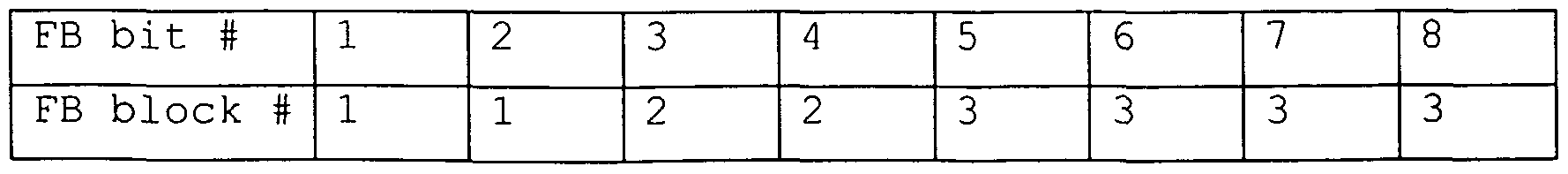
According to a second embodiment, an idea is to control the length of the feedback word in order to avoid the situation where channel changes remarkable during the feedback delay. The change of the feedback word is done in the following way: firstly, the feedback mode is designed such that the feedback word corresponding to the scheme is built up from several shorter feedback words. That is, the feedback word is built up from smaller building blocks for example as follows
Figure imgf000015_0003
Here an FB word can be 2, 4 or 8 bits long and its structure is hierarchical in the sense that if the channel remains constant or almost constant during the feedback delay, then performance is improving when the FB word is becoming longer.
Hence, feedback words of different lengths can be used based on the temporal properties of the channel. If the channel is changing very slowly (i.e., the mobile is moving slowly) then the longest available word can be used, and when the changes of the channel become more rapid then shorter and shorter words are applied. In the above example, there are three alternatives for the FB word.
Control of FB word
Several mechanisms for controlling the length of the feedback word can be designed. The length of FB word can be decided, for example, using the following schemes:
• Compute the level crossing rate in MS or BS and estimate the velocity of mobile from that measure. This is an indirect approach since we are not interested in the mobile speed as such but the performance of FB, and therefore it may not give reliable results from FB performance point of view. • Compute SNR gain from the pilot channel in MS or BS by using the previous transmit weights with time delay d and from time to time ask BS or MS to change the length of the word. This is a direct approach in the sense that by trying out different FB lengths and consequently different Tx weights and delays the results are proportional to expected SNR improvement of the corresponding FB mode. However, this requires extra computational load and memory.
• Study the previous feedback commands during some time interval in MS or BS and send FB change requests to BS or MS based on that information. This control scheme is very simple to implement. Since we know what is the length of the present FB word, we can compute different measures based on the previously received FB words. For example, it is assumed that the length of the present FB word is 5 bits and the following FB words have been received from two separate mobiles
Figure imgf000017_0001
Already this short time gives a hint that the channel corresponding to the first mobile is changing rapidly and therefore it seems that a shorter FB word should be allocated to mobile 1. On the other hand, it is seen that the FB word corresponding to the second mobile is not changing much. Thus the present feedback scheme can be kept or the feedback word can even be enlarged. Instead of enlarging the FB word BS may also choose to collect more than one consecutive feedback signals and process them jointly in order to diminish the effect of feedback errors.
Example of a control algorithm
Let us denote the binary feedback words by wt . The Hamming distance between words , and w is given by
d(w, ,w ) = ∑|w,(/) - wΛ (7)| , , = (w, (1), w, (2), ... , w, (L)) ,
where it is assumed that the length of the feedback word is L bits. It is noticed that the value of the time index t changes only after each L feedback bits. Further we write d(t) = d(wl ,w,_,) and define the decision variable D(t) by / D(t) = ∑κ'-kd(t + T - k) , 0 < κ < l ,
where values of K and T are found by simulations, field measurements etc. when a specific feedback scheme has been chosen. If we have, for example, three different feedback modes, where the corresponding feedback words are of the length Z,, < L2 < , , then we set two threshold levels for the decision variable D(t) and change the mode always when appropriate threshold level have been crossed.
All of the above schemes assume that FB control information is transmitted either from mobile to BS or vice versa. Thus, some of the available capacity needs to be allocated for that purpose. However, the update rate of this control information can be several frames since temporal properties of the channel are not changing rapidly and only few bits of control information is needed.
Example
In the following, an example scheme (4 antennas) is described that is built up in three stages. That is, the FB word corresponding to this scheme can be of length 2, 4 or even 8 bits. Each new stage is based on the previous stage.
Description of stages 1-3:
Stage 1. (Length of the FB word is 2 bits) This stage uses two feedback bits in order to find the best channel in terms of power among the 4 possible alternatives.
Stage 2. (Length of the FB word is 4 bits) Now we use first stage 1. That is, we first decide which antenna is best in terms of gain and define first 2 FB bits. Then we choose some antenna (known for both transmitter and receiver; for example, if antenna 1 is best, then the chosen antenna is antenna 2, etc.) and adjust the relative phases between these two antennas. Third and fourth FB bits are now defined. It should be noticed that since the transmitter knows which antenna is the best one (in terms of gains) , antenna weights can be applied given in a manner that is explained in accordance with the first embodiment.
Stage 3. (Length of the FB word is 8 bits) Now we use first stage 2. Then we choose some third antenna (known for both transmitter and receiver) and adjust the relative phase between first two antennas and third antenna. This gives us fifth and sixth FB bits. Again antenna weights are changed in the transmitter. The final two FB bits are used in order to adjust the relative phase between the last antenna and three already adjusted antennas. Antenna weights are updated in each step.
Full order information requires log2(M!) FB bits, but it is possible to apply feedback refinement to transmit powers analogous to FDD WCDMA mode 1 which applies the refinement to phases. That is, during each slot only partial information is signalled, e.g. slot i tells whether antenna 1 is stronger than antenna 2, slot i+1 tells if antenna 3 is stronger than antenna 4, slot i+2 if antenna 2 is stronger than antenna 3, etc. Alternatively, only the strongest antenna can be signaled from MS to BS, and the BS maintains the ordered list of the antenna gains. Whenever new order information arrives, the list is updated so that, for example, the previous strongest antenna is moved to the second strongest position in the list. In general, the partial feedback can obey round robin signaling, where slot i tells the strongest antenna, next slot tells the second strongest antenna, etc., and BS maintais ordered list of the antenna gains. Modification to spatial adaptation
According to a third embodiment, multiple feedback words of different lengths are calculated and applied to the received signal after an appropriate delay. This gives rise to different ordered covariance matrices C and the one with the largest eigenvalue indicates the best feedback signal format for the current mobile speed. The calculation can be performed in MS or BS, and it maps the mobile speed directly to the expected gain of a closed loop mode. This is different from the typical Doppler shift estimation which is an indirect measure and may not provide appropriate information for switching between different closed loop modes. For example, when the correlation between transmit antennas is large, phase differences between the antennas as a function of mobile speed do not experience as rapid fluctuations as in the case of uncorrelated transmit antennas. The procedure is similar to setting SIR target in outer loop power control, i.e. closed loop modes are required to provide some gain target, and mode switching is performed based on the estimated SNR gains. Furthermore, gain estimation in BS may utilize additional information obtained from the received power control commands to increase the reliability of the mode switching by, for example, shortening the feedback word if the transmitted power shows an increasing trend.
Instead of calculating different matrices C as specified in the previous paragraph, it is possible to calculate a single C and monitor the corresponding transmit weights when deciding whether to change the structure of the feedback message. For example, if all weights are close to each other the signaling of the order information can be turned off so that only phase feedback is applied. If some transmit weight becomes small, the corresponding phase feedback can be turned off. MS or BS can estimate both R and C simultaneously and monitor the corresponding gains in order to perform mode switching. For example, if the maximum eigenvalues of R and C are close to each other MS and BS could apply only long-term feedback to signal the eigenvector corresponding to the maximum eigenvalue of R.
While the invention has been described with reference to preferred embodiments, the description is illustrative of the invention and is not to be construed as limiting the invention. Various modifications and applications may occur to those skilled in the art without departing from the true spirit and scope of the invention as defined by the appended claims.
References
[1] 3GPP RAN WG1: „UTRA Physical Layer General Description", 25.201, Ver 3.0.2, March 2000
[2] 3GPP RAN WG1 : performance results of basis selection transmit diversity for 4 antennas", Rl-00-1073 [3] 3GPP RAN WG1 : „Advanced closed loop Tx diversity concept (eigenbeamformer) ", Rl-00-0853
[4] Jyri Hamalainen, Risto Wichman: „ Closed-loop transmit diversity for FDD WCDMA systems", 34th Asilomar Conference on Signal, Systems and Computers, Oct. -Nov. 2000

Claims

CLAIMS :
1. A method of influencing the transmission of signals from a transmitting device to a receiving device in a communication system comprising at least one transmitting device and at least one receiving device, said method comprising the steps of: processing received transmission signals; generating a feedback signal to be transmitted to the transmitting device, on the basis of the processed signals; and determining transmit weights to be applied to transmission signals, in accordance with the feedback signal.
2. A method according to claim 1, wherein transmission signals are received in a receiving device from two or more transmitting elements of a transmitting device for transmission using transmit diversity technique.
3. A method according to claim 2, wherein the transmitting elements are divided into groups which are combined incoherently.
4. A method according to claim 2, comprising the steps of: detecting differences between transmission signals received from different transmitting elements; adapting channel coefficients between the transmitting elements and the receiving device in accordance with the detected signal differences; forming an ordered covariance matrix C of the adapted channel coefficients; evaluating the largest eigenvalue of C; and calculating the eigenvector corresponding to the largest eigenvalue, the eigentvector corresponding to the transmit weights.
5. A method according to claim 4, wherein the elements of C are measured using low-pass filtering.
6. A method according to claim 5, wherein the elements of C comprise spatial correlation of the transmitting elements.
7. A method according to claim 4, wherein C is formed in the receiving device and the feedback signal is generated in accordance with the calculated eigenvector.
8. A method according to claim 4, wherein the feedback signal is generated in accordance with the detected signal differences, and C is formed in the transmitting device on the basis of the received feedback signal and the eigenvector is calculated in the transmitting device.
9. A method according to claim 6, wherein a matrix C is formed for each spatial correlation order of transmitting elements and corresponding transmit weights are calculated.
10. A method according to claim 4, wherein, when the transmission signals have different transmit powers, transmission signals are estimated in the receiving device and C is formed on the basis of the estimated transmission signals.
11. A method according to claim 9, wherein the number of transmitting elements in each spatial correlation order is reduced according to the detected signal differences.
12. A method according to claim 7, wherein the feedback signal comprises at least one of order and phase information of one transmitting element to the other transmitting elements .
13. A method according to claim 1, wherein the feedback signal comprises a feedback word which is generated according to one of two or more feedback modes.
14. A method according to claim 13, wherein the different feedback modes correspond to different feedback word lengths.
15. A method according to claim 14, wherein the length of the feedback word is controlled in accordance with temporal properties of a channel between the transmitting device and the receiving device.
16. A method according to claim 15, wherein the controlling of the feedback word length comprises the steps of: computing the level crossing rate; estimating the velocity of the receiving device from the computed level crossing rate; and deciding the feedback word length in accordance with the estimated velocity.
17. A method according to claim 15, wherein the controlling of the feedback word length comprises the steps of: a) computing the SNR gain from a pilot channel between the transmitting device and the receiving device by using the previous transmit weights with a time delay; b) requesting change of feedback word length; c) determining transmit weights in accordance with the changed feedback word length; d) repeating steps a) to c) and deciding expected SNR improvements of the corresponding feedback word lengths; and e) selecting the feedback word length with the best expected SNR improvement.
18. A method according to claim 15, wherein the controlling of the feedback word length comprises the steps of: comparing previous feedback words and detecting the change in the feedback words of same length; and selecting a feedback word length in accordance with the detected change in the feedback signals.
19. A method according to claim 18, wherein threshold levels for switching from one feedback word length to another are determined on the basis of the amount of change of the feedback words of the respective same lengths.
20. A method according to claim 15, wherein feedback control information is determined in the receiving device and transmitted to the transmitting device.
21. A method according to claim 15, wherein feedback control information is determined in the transmitting device and transmitted to the receiving station.
22. A method according to claim 14, wherein the feedback word lengths comprise a length of zero.
23. A method according to claim 4, wherein the feedback signal comprises two or more feedback words of different lengths, an ordered covariance matrix C is formed for each feedback word length, the largest eigenvalue is evaluated for each ordered covariance matrix C, the largest eigenvalues are compared, and the feedback word corresponding to the matrix C with the largest eigenvalue of the largest eigenvalues is determined as best feedback mode.
24. A method according to claim 23, wherein the determined best feedback mode corresponds to the speed of the receiving device .
25. A method according to claim 4, wherein a single matrix C is calculated and the corresponding transmit weights are monitored in order to deciding whether to change a structure of the feedback signal.
26. A communication system for influencing the transmission of signals from a transmitting device to a receiving device, said communication system comprising at least one transmitting device and at least one receiving device, wherein the receiving device is arranged to process received transmission signals, generate a feedback signal on the basis of the processed signals and transmit the feedback signal to the transmitting device, and the transmitting device is arranged to receive the transmitted feedback signal, determine transmit weights in accordance with the feedback signal and apply the determined transmit weights to transmission signals.
27. A system according to claim 26, wherein the receiving device receives transmission signals from two or more transmitting elements of the transmitting device for transmission using transmit diversity technique.
28. A system according to claim 27, wherein the receiving device is arranged to detect differences between transmission signals received from different transmitting elements, adapt channel coefficients between the transmitting elements and the receiving device in accordance with the detected signal differences, form an ordered covariance matrix C of the adapted channel coefficients, evaluate the largest eigenvalue of C, and calculate the eigenvector corresponding to the largest eigenvalue, and generate a feedback signal in accordance with the calculated eigenvector.
29. A system according to claim 27, wherein the receiving device is arranged to detect differences between transmission signals received from different transmitting elements and generate a feedback signal in accordance with the detected signal differences, and the transmitting device is arranged to adapt channel coefficients between the transmitting elements and the receiving device in accordance with the received feedback signal, form an ordered covariance matrix C of the adapted channel coefficients, evaluate the largest eigenvalue of C, and calculate the eigenvector corresponding to the largest eigenvalue, the eigenvector corresponding to the transmit weights.
30. A system according to claim 28 or 29, wherein the elements of C are measured using low-pass filtering.
31. A system according to claim 30, wherein the elements of C comprise spatial correlation of the transmitting elements.
32. A system according to claim 31, wherein a matrix C is formed for each spatial correlation order of transmitting elements and corresponding transmit weights are calculated.
33. A system according to claim 32, whereiji the number of transmitting elements in each spatial correlation order is reduced according to the detected signal differences.
34. A system according to claim 28 or 29, wherein the feedback signal comprises at least one of order and phase information of one transmitting element to the other transmitting elements.
35. A system according to claim 26, wherein the feedback signal comprises a feedback word which is generated by the receiving device according to one of two ore more feedback modes . *
- 27 -
36. A system according to claim 35, wherein the different feedback modes correspond to different feedback word lengths.
37. A system according to claim 36, said system comprising means for controlling the length of the feedback word in accordance with temporal properties of a channel between the transmitting device and the receiving device.
38. A system according to claim 37, wherein the means for controlling the feedback word length are arranged to compute the level crossing rate; estimate the velocity of the receiving device from the computed level crossing rate; and decide the feedback word length in accordance with the estimated velocity.
39. A system according to claim 37, wherein the means for controlling the feedback word length are adapted to a) compute the SNR from a pilot channel between the transmitting device and the receiving device by using the previous transmit weights with a time delay; b) request change of feedback word length; c) determine transmit weights in accordance with the changed feedback word length; d) repeat steps a) to c) and decide expected SNR improvements of the corresponding feedback word lengths; and e) select the feedback word length with the best expected SNR improvement.
40. A system according to claim 37, wherein the means for controlling the feedback word length are arranged to compare previous feedback words and detecting the change in the feedback words of same length; and select a feedback word length in accordance with the detected change in the feedback signals.
41. A system according to claim 40, wherein the means are further arranged to determine threshold levels for switching from one feedback word length to another on the basis of the amount of change of the feedback words of the respective same lengths .
42. A system according to claim 37, wherein the means for controlling the feedback word length are located in the receiving device, and feedback control information is determined in the receiving device and transmitted to the transmitting device.
43. A system according to claim 37, wherein the means for controlling the feedback word length are located in the transmitting device, and feedback control information is determined in the transmitting device and transmitted to the receiving station.
44. A system according to claim 36, wherein the feedback word lengths comprise a length of zero.
45. A system according to claim 28 or 29, wherein the feedback signal comprises two or more feedback words of different lengths, an ordered covariance matrix C is formed for each feedback word length, the largest eigenvalue is evaluated for each ordered covariance matrix C, the largest eigenvalues are compared, and the feedback word corresponding to the matrix C with the largest eigenvalue of the largest eigenvalues is determined as best feedback mode.
46. A system according to claim 45, wherein the determined best feedback mode corresponds to the speed of the receiving device .
47. A receiving device in a communication system for influencing the transmission of signals from a transmitting device to a receiving device, said communication system comprising at least one transmitting device and at least one receiving device, wherein said receiving device is arranged to process received transmission signals, generate a feedback signal on the basis of the processed signals and transmit the feedback signal to the transmitting device.
48. A receiving device according to claim 47, being arranged to receive transmission signals from two or more transmitting elements of the transmitting device for transmission using transmit diversity technique.
49. A receiving device according to claim 48, being arranged to detect differences between transmission signals received from different transmitting elements, adapt channel coefficients between the transmitting elements and the receiving device in accordance with the detected signal differences, form an ordered covariance matrix C of the adapted channel coefficients, evaluate the largest eigenvalue of C, and calculate the eigenvector corresponding to the largest eigenvalue, and generate a feedback signal in accordance with the calculated eigenvector.
50. A receiving device according to claim 47, wherein the feedback signal comprises a feedback word which is generated by said receiving device according to one of two ore more feedback modes.
51. A receiving device according to claim 50, wherein the different feedback modes correspond to different feedback word lengths.
52. A receiving device according to claim 51, comprising means for controlling the length of the feedback word in accordance with temporal properties of a channel between the transmitting device and the receiving device, wherein said receiving device is arranged to transmit determined feedback control information to the transmitting device.
53. A receiving device according to claim 49, wherein the feedback signal comprises two or more feedback words of different lengths, and said receiving device is arranged to form an ordered covariance matrix C for each feedback word length, evaluate the largest eigenvalue for each ordered covariance matrix C, compare the largest eigenvalues, and determine the feedback word corresponding to the matrix C with the largest eigenvalue of the largest eigenvalues as best feedback mode.
54. A transmitting device in a communication system for influencing the transmission of signals from a transmitting device to a receiving device, said communication system comprising at least one transmitting device and at least one receiving device, wherein the transmitting device is arranged to receive feedback signal transmitted from a receiving device, determine transmit weights in accordance with the feedback signal and apply the determined transmit weights to transmission signals.
55. A transmitting device according to claim 54, wherein the transmitting device transmits transmission signals from two or more transmitting elements to the receiving device for transmission using transmit diversity technique.
56. A transmitting device according to claim 55, being arranged to adapt channel coefficients between the transmitting elements and the receiving device in accordance with the received feedback signal, form an ordered covariance matrix C of the adapted channel coefficients, evaluate the largest eigenvalue of C, and calculate the eigenvector corresponding to the largest eigenvalue, the eigentvector corresponding to the transmit weights.
57. A transmitting device according to claim 54, wherein the received feedback signal comprises a feedback word which is generated according to one of two ore more feedback modes.
58. A transmitting device according to claim 57, wherein the different feedback modes correspond to different feedback word lengths.
59. A transmitting device according to claim 58, comprising means for controlling the length of the feedback word in accordance with temporal properties of a channel between the transmitting device and the receiving device, wherein said transmitting device is arranged to transmit determined feedback control information to the receiving device.
60. A transmitting device according to claim 56, wherein the feedback signal comprises two or more feedback words of different lengths, and said transmitting device is arranged to form an ordered covariance matrix C for each received feedback word, evaluate the largest eigenvalue for each ordered covariance matrix C, compare the largest eigenvalues, and determine the feedback word corresponding to the matrix C with the largest eigenvalue of the largest eigenvalues as best feedback mode.
PCT/EP2001/005833 2001-05-21 2001-05-21 Communication system and method using transmit diversity WO2002095982A1 (en)

Priority Applications (5)

Application Number Priority Date Filing Date Title
PCT/EP2001/005833 WO2002095982A1 (en) 2001-05-21 2001-05-21 Communication system and method using transmit diversity
EP01951511A EP1389367A1 (en) 2001-05-21 2001-05-21 Communication system and method using transmit diversity
US10/478,242 US7224943B2 (en) 2001-05-21 2001-05-21 Communication system and method using transmit diversity
US11/367,447 US7643799B2 (en) 2001-05-21 2006-03-06 Communication system and method using transmit diversity
US11/367,448 US7599666B2 (en) 2001-05-21 2006-03-06 Communication system and method using transmit diversity

Applications Claiming Priority (1)

Application Number Priority Date Filing Date Title
PCT/EP2001/005833 WO2002095982A1 (en) 2001-05-21 2001-05-21 Communication system and method using transmit diversity

Related Child Applications (3)

Application Number Title Priority Date Filing Date
US10478242 A-371-Of-International 2001-05-21
US11/367,447 Division US7643799B2 (en) 2001-05-21 2006-03-06 Communication system and method using transmit diversity
US11/367,448 Division US7599666B2 (en) 2001-05-21 2006-03-06 Communication system and method using transmit diversity

Publications (1)

Publication Number Publication Date
WO2002095982A1 true WO2002095982A1 (en) 2002-11-28

Family

ID=8164426

Family Applications (1)

Application Number Title Priority Date Filing Date
PCT/EP2001/005833 WO2002095982A1 (en) 2001-05-21 2001-05-21 Communication system and method using transmit diversity

Country Status (3)

Country Link
US (3) US7224943B2 (en)
EP (1) EP1389367A1 (en)
WO (1) WO2002095982A1 (en)

Cited By (5)

* Cited by examiner, † Cited by third party
Publication number Priority date Publication date Assignee Title
WO2007084682A1 (en) * 2006-01-20 2007-07-26 Atc Technologies, Llc Systems and methods for forward link closed loop beamforming
WO2008068547A1 (en) * 2006-12-08 2008-06-12 Nokia Corporation, Calibration in a spread spectrum communications system
WO2008082345A1 (en) * 2007-01-04 2008-07-10 Telefonaktiebolaget L M Ericsson (Publ) Method and apparatus for improving transmission efficiency in a mobile radio communications system
WO2008133580A1 (en) * 2007-04-26 2008-11-06 Telefonaktiebolaget L M Ericsson (Publ) Multiple-input, multiple-output communication system with reduced feedback
DE10260290B4 (en) * 2002-12-20 2014-02-13 Siemens Aktiengesellschaft Method for data transmission and communication system

Families Citing this family (57)

* Cited by examiner, † Cited by third party
Publication number Priority date Publication date Assignee Title
AU2001239831A1 (en) 2000-02-25 2001-09-03 Telecommunication Systems, Inc. Prepaid short messaging
US7522911B2 (en) 2000-04-11 2009-04-21 Telecommunication Systems, Inc. Wireless chat automatic status tracking
US8744384B2 (en) 2000-07-20 2014-06-03 Blackberry Limited Tunable microwave devices with auto-adjusting matching circuit
GB0022633D0 (en) * 2000-09-15 2000-11-01 Koninkl Philips Electronics Nv Secondary station and method of operating the station
WO2002095982A1 (en) * 2001-05-21 2002-11-28 Nokia Corporation Communication system and method using transmit diversity
US7167526B2 (en) * 2001-06-07 2007-01-23 National Univ. Of Singapore Wireless communication apparatus and method
US7181167B2 (en) * 2001-11-21 2007-02-20 Texas Instruments Incorporated High data rate closed loop MIMO scheme combining transmit diversity and data multiplexing
US7853272B2 (en) * 2001-12-21 2010-12-14 Telecommunication Systems, Inc. Wireless network tour guide
US7164726B1 (en) * 2002-06-28 2007-01-16 Arraycomm, Llc. Broadcast burst using spatial diversity for a radio communications system
JP3887618B2 (en) * 2003-08-08 2007-02-28 松下電器産業株式会社 Mobile station apparatus and reception method in mobile station apparatus
JP2004325239A (en) * 2003-04-24 2004-11-18 Sharp Corp Antenna gain specifying device and radio communication device
KR100575930B1 (en) * 2003-05-16 2006-05-02 삼성전자주식회사 Method and apparatus for mode transition of transmit diversity in mobile communication system using transmit diversity
GB0311856D0 (en) * 2003-05-22 2003-06-25 Nokia Corp Transmissions from a station with multiple antennae
DE10327896A1 (en) * 2003-06-20 2005-01-05 Siemens Ag Method for determining an antenna weighting factor
FR2862173B1 (en) * 2003-11-07 2006-01-06 Thales Sa METHOD FOR BLINDLY DEMODULATING HIGHER ORDERS OF A LINEAR WAVEFORM TRANSMITTER
KR100587417B1 (en) * 2003-12-22 2006-06-08 한국전자통신연구원 Apparatus for adatively transmitting and receiving in wireless communication system using frequency division multiplexing
US9406444B2 (en) 2005-11-14 2016-08-02 Blackberry Limited Thin film capacitors
US9559871B2 (en) * 2006-01-10 2017-01-31 Alcatel-Lucent Usa Inc. Composite channel equalization of a wideband wireless communication system
US7711337B2 (en) 2006-01-14 2010-05-04 Paratek Microwave, Inc. Adaptive impedance matching module (AIMM) control architectures
CN101432993B (en) * 2006-04-27 2012-10-03 日本电气株式会社 Mobile communication device and reception quality information creation method
US7535312B2 (en) 2006-11-08 2009-05-19 Paratek Microwave, Inc. Adaptive impedance matching apparatus, system and method with improved dynamic range
US7714676B2 (en) 2006-11-08 2010-05-11 Paratek Microwave, Inc. Adaptive impedance matching apparatus, system and method
KR100961889B1 (en) * 2006-11-17 2010-06-09 삼성전자주식회사 Apparatus and method for performing sequential scheduling in multiple-input multiple-output system
US7917104B2 (en) 2007-04-23 2011-03-29 Paratek Microwave, Inc. Techniques for improved adaptive impedance matching
US8213886B2 (en) 2007-05-07 2012-07-03 Paratek Microwave, Inc. Hybrid techniques for antenna retuning utilizing transmit and receive power information
US7830978B2 (en) * 2007-08-31 2010-11-09 Alcatel Lucent Determining channel matrices by correlated transmissions to different channels
US7991363B2 (en) 2007-11-14 2011-08-02 Paratek Microwave, Inc. Tuning matching circuits for transmitter and receiver bands as a function of transmitter metrics
US8483310B2 (en) * 2008-02-25 2013-07-09 Telefonaktiebolaget Lm Ericsson (Publ) Method of and a device for precoding transmit data signals in a wireless MIMO communication system
US8699984B2 (en) * 2008-02-25 2014-04-15 Csr Technology Inc. Adaptive noise figure control in a radio receiver
US8072285B2 (en) 2008-09-24 2011-12-06 Paratek Microwave, Inc. Methods for tuning an adaptive impedance matching network with a look-up table
US8954028B2 (en) 2008-09-25 2015-02-10 Telecommunication Systems, Inc. Geo-redundant and high reliability commercial mobile alert system (CMAS)
US20100099364A1 (en) * 2008-10-22 2010-04-22 Futurewei Technologies, Inc. System and Method for Transmitting and Error Handling Control Feedback Information
US8537785B2 (en) * 2009-03-05 2013-09-17 Huawei Technologies Co., Ltd Method and apparatus for cell/sector coverage of a public channel through multiple antennas
GB2472074B (en) * 2009-07-24 2012-05-16 Vodafone Plc System and method utilising transmit diversity
US9026062B2 (en) 2009-10-10 2015-05-05 Blackberry Limited Method and apparatus for managing operations of a communication device
US8803631B2 (en) 2010-03-22 2014-08-12 Blackberry Limited Method and apparatus for adapting a variable impedance network
US8860526B2 (en) * 2010-04-20 2014-10-14 Blackberry Limited Method and apparatus for managing interference in a communication device
US8509831B2 (en) * 2010-09-27 2013-08-13 Hitachi, Ltd. Joint user equipment scheduling and cluster formation for distributed antenna systems
US9379454B2 (en) 2010-11-08 2016-06-28 Blackberry Limited Method and apparatus for tuning antennas in a communication device
WO2012082151A2 (en) 2010-12-13 2012-06-21 Telecommunication Systems, Inc. Location services gateway server
US8712340B2 (en) * 2011-02-18 2014-04-29 Blackberry Limited Method and apparatus for radio antenna frequency tuning
US8655286B2 (en) 2011-02-25 2014-02-18 Blackberry Limited Method and apparatus for tuning a communication device
US9705190B2 (en) * 2011-03-02 2017-07-11 Keysight Technologies Singapore (Holdings) Ptd. Ltd. Over-the-air test
US8594584B2 (en) 2011-05-16 2013-11-26 Blackberry Limited Method and apparatus for tuning a communication device
WO2013022826A1 (en) 2011-08-05 2013-02-14 Research In Motion Rf, Inc. Method and apparatus for band tuning in a communication device
US8929854B2 (en) 2011-10-27 2015-01-06 Telecommunication Systems, Inc. Emergency text messaging
US8948889B2 (en) 2012-06-01 2015-02-03 Blackberry Limited Methods and apparatus for tuning circuit components of a communication device
US9853363B2 (en) 2012-07-06 2017-12-26 Blackberry Limited Methods and apparatus to control mutual coupling between antennas
US9246223B2 (en) 2012-07-17 2016-01-26 Blackberry Limited Antenna tuning for multiband operation
US9350405B2 (en) 2012-07-19 2016-05-24 Blackberry Limited Method and apparatus for antenna tuning and power consumption management in a communication device
US9413066B2 (en) 2012-07-19 2016-08-09 Blackberry Limited Method and apparatus for beam forming and antenna tuning in a communication device
US9362891B2 (en) 2012-07-26 2016-06-07 Blackberry Limited Methods and apparatus for tuning a communication device
US9374113B2 (en) 2012-12-21 2016-06-21 Blackberry Limited Method and apparatus for adjusting the timing of radio antenna tuning
US10404295B2 (en) 2012-12-21 2019-09-03 Blackberry Limited Method and apparatus for adjusting the timing of radio antenna tuning
US20140329472A1 (en) * 2013-05-03 2014-11-06 CommSense LLC Antenna Environment Sensing Device
US9408047B2 (en) 2013-10-10 2016-08-02 Telecommunication Systems, Inc. Read acknowledgement interoperability for text messaging and IP messaging
US9438319B2 (en) 2014-12-16 2016-09-06 Blackberry Limited Method and apparatus for antenna selection

Citations (1)

* Cited by examiner, † Cited by third party
Publication number Priority date Publication date Assignee Title
WO2000072464A1 (en) * 1999-05-19 2000-11-30 Nokia Networks Oy Transmit diversity method and system

Family Cites Families (15)

* Cited by examiner, † Cited by third party
Publication number Priority date Publication date Assignee Title
US5151622A (en) * 1990-11-06 1992-09-29 Vitelic Corporation CMOS logic circuit with output coupled to multiple feedback paths and associated method
US20010016504A1 (en) * 1998-04-03 2001-08-23 Henrik Dam Method and system for handling radio signals in a radio base station
US6504884B1 (en) * 1999-05-12 2003-01-07 Analog Devices, Inc. Method for correcting DC offsets in a receiver
KR100689398B1 (en) * 1999-10-09 2007-03-08 삼성전자주식회사 Method and apparatus for controling transmit antenna diversity of mobile communication system
FI20001944A (en) * 2000-09-04 2002-03-05 Nokia Corp Method and arrangement for transmitting a digital signal
KR100493150B1 (en) * 2000-04-10 2005-06-02 삼성전자주식회사 Method and apparatus of the optimum weight estimator of the closed loop transmit diversity for mobile communications
US6778514B1 (en) 2000-05-31 2004-08-17 Cadence Design Systems, Inc. Subspace combination of multisensor output signals
US6952455B1 (en) * 2000-08-02 2005-10-04 Via Telecom, Co., Ltd. Adaptive antenna method and apparatus
WO2002095982A1 (en) * 2001-05-21 2002-11-28 Nokia Corporation Communication system and method using transmit diversity
US7010030B2 (en) * 2001-07-20 2006-03-07 Koninklijke Philips Electronics N.V. Software definable block adaptive decision feedback equalizer
EP1489772B1 (en) * 2002-03-22 2014-09-10 Huawei Technologies Co., Ltd. A self - adapting weighted space time transmitting diversity method and system thereof
US6842632B2 (en) * 2002-12-30 2005-01-11 Nokia Corporation Apparatus, and associated method, for facilitating antenna weight selection utilizing deterministic perturbation gradient approximation
AU2002368163A1 (en) * 2002-08-05 2004-02-25 Nokia Corporation Transmission diversity with two cross-polarised antennas arrays
US7515541B2 (en) * 2003-08-08 2009-04-07 Intel Corporation Transmission of data with feedback to the transmitter in a wireless local area network or the like
US7039370B2 (en) * 2003-10-16 2006-05-02 Flarion Technologies, Inc. Methods and apparatus of providing transmit and/or receive diversity with multiple antennas in wireless communication systems

Patent Citations (1)

* Cited by examiner, † Cited by third party
Publication number Priority date Publication date Assignee Title
WO2000072464A1 (en) * 1999-05-19 2000-11-30 Nokia Networks Oy Transmit diversity method and system

Non-Patent Citations (3)

* Cited by examiner, † Cited by third party
Title
"Advanced closed loop Tx diversity concept", 3GPP TSG RAN WG 1, XX, XX, 4 July 2000 (2000-07-04), XP002169992 *
HAMALAINEN J ET AL: "Closed-loop transmit diversity for FDD WCDMA systems", CONFERENCE RECORD OF THE THIRTY-FOURTH ASILOMAR CONFERENCE ON SIGNALS, SYSTEMS AND COMPUTERS (CAT. NO.00CH37154), CONFERENCE RECORD OF THE THIRTY-FOURTH ASILOMAR CONFERENCE ON SIGNALS, SYSTEMS AND COMPUTERS, PACIFIC GROVE, CA, USA, 29 OCT.-1 NOV. 200, 2000, Piscataway, NJ, USA, IEEE, USA, pages 111 - 115 vol.1, XP002193118, ISBN: 0-7803-6514-3 *
HAMALAINEN J ET AL: "Feedback schemes for FDD WCDMA systems in multipath environments", IEEE VTS 53RD VEHICULAR TECHNOLOGY CONFERENCE, SPRING 2001. PROCEEDINGS (CAT. NO.01CH37202), IEEE VTS 53RD VEHICULAR TECHNOLOGY CONFERENCE. PROCEEDINGS, RHODES, GREECE, 6-9 MAY 2001, 2001, Piscataway, NJ, USA, IEEE, USA, pages 238 - 242 vol.1, XP002193119, ISBN: 0-7803-6728-6 *

Cited By (9)

* Cited by examiner, † Cited by third party
Publication number Priority date Publication date Assignee Title
DE10260290B4 (en) * 2002-12-20 2014-02-13 Siemens Aktiengesellschaft Method for data transmission and communication system
WO2007084682A1 (en) * 2006-01-20 2007-07-26 Atc Technologies, Llc Systems and methods for forward link closed loop beamforming
US8090041B2 (en) 2006-01-20 2012-01-03 Atc Technologies Llc Systems and methods for forward link closed loop beamforming
WO2008068547A1 (en) * 2006-12-08 2008-06-12 Nokia Corporation, Calibration in a spread spectrum communications system
WO2008082345A1 (en) * 2007-01-04 2008-07-10 Telefonaktiebolaget L M Ericsson (Publ) Method and apparatus for improving transmission efficiency in a mobile radio communications system
WO2008082344A1 (en) * 2007-01-04 2008-07-10 Telefonaktiebolaget L M Ericsson (Publ) Method and apparatus for improving transmission efficiency in a mobile radio communications system
US8295869B2 (en) 2007-01-04 2012-10-23 Telefonaktiebolaget Lm Ericsson (Publ) Method and apparatus for improving transmission efficiency in a mobile radio communications system
WO2008133580A1 (en) * 2007-04-26 2008-11-06 Telefonaktiebolaget L M Ericsson (Publ) Multiple-input, multiple-output communication system with reduced feedback
US8199840B2 (en) 2007-04-26 2012-06-12 Telefonaktiebolaget Lm Ericsson (Publ) Multiple-input, multiple-output communication system with reduced feedback

Also Published As

Publication number Publication date
US7599666B2 (en) 2009-10-06
US20040147227A1 (en) 2004-07-29
US7224943B2 (en) 2007-05-29
US20060148415A1 (en) 2006-07-06
US7643799B2 (en) 2010-01-05
US20060148427A1 (en) 2006-07-06
EP1389367A1 (en) 2004-02-18

Similar Documents

Publication Publication Date Title
US7643799B2 (en) Communication system and method using transmit diversity
EP1410528B1 (en) Channel prediction in closed loop transmit diversity
EP1366579B1 (en) Method for controlling the weighting of a data signal in the at least two antenna elements of a radio connection unit, module and communications system
US7447270B1 (en) Method for controlling the data signal weighting in multi-element transceivers and corresponding devices and telecommunications network
US20070177681A1 (en) Mimo-ofdm system using eigenbeamforming method
US7457590B2 (en) Method, apparatus and system for use in the transmission of wireless communications using multiple antennas
KR20170003921A (en) Updates to mu-mimo rate adaptation algorithm
EP1306983B1 (en) Mobile communication apparatus including multiple transmit and receive antennas and mobile communication method thereof
JP2004511119A (en) Beam forming method
US7006041B2 (en) Radio receiver, radio transmitter and impedance control method
KR20070059992A (en) Beam-forming apparatus and method in smart antenna systems
US10735853B2 (en) Stochastic transmission/reception method and apparatus for MU-MIMO scheme in MIMO radio communication system
US8612502B2 (en) Simplified equalization for correlated channels in OFDMA
WO2006132707A2 (en) Method and system for transmitter beamforming
WO2004034614A1 (en) A method and device for estimating a signal to interference ratio (sir) in wcdma systems
KR100767129B1 (en) Method for controlling the formation of a downlink beam
JP4170789B2 (en) Wireless communication system, receiving station, and wireless communication control method
JP2005536130A (en) Channel estimation method and radio communication system
JP5009826B2 (en) Wireless communication system, wireless communication apparatus, and communication control method
JP5006224B2 (en) Wireless communication system, wireless communication apparatus, and communication control method
WO2002043272A1 (en) Communication system and method using transmit diversity

Legal Events

Date Code Title Description
AK Designated states

Kind code of ref document: A1

Designated state(s): AE AG AL AM AT AU AZ BA BB BG BR BY BZ CA CH CN CR CU CZ DE DK DM DZ EE ES FI GB GD GE GH GM HR HU ID IL IN IS JP KE KG KP KR KZ LC LK LR LS LT LU LV MA MD MG MK MN MW MX MZ NO NZ PL PT RO RU SD SE SG SI SK SL TJ TM TR TT TZ UA UG US UZ VN YU ZA ZW

AL Designated countries for regional patents

Kind code of ref document: A1

Designated state(s): GH GM KE LS MW MZ SD SL SZ TZ UG ZW AM AZ BY KG KZ MD RU TJ TM AT BE CH CY DE DK ES FI FR GB GR IE IT LU MC NL PT SE TR BF BJ CF CG CI CM GA GN GW ML MR NE SN TD TG

121 Ep: the epo has been informed by wipo that ep was designated in this application
WWE Wipo information: entry into national phase

Ref document number: 2001951511

Country of ref document: EP

DFPE Request for preliminary examination filed prior to expiration of 19th month from priority date (pct application filed before 20040101)
WWE Wipo information: entry into national phase

Ref document number: 10478242

Country of ref document: US

WWP Wipo information: published in national office

Ref document number: 2001951511

Country of ref document: EP

REG Reference to national code

Ref country code: DE

Ref legal event code: 8642

NENP Non-entry into the national phase

Ref country code: JP

WWW Wipo information: withdrawn in national office

Ref document number: 2001951511

Country of ref document: EP