WO2002039414A2 - Method and apparatus for verifying a color of an led in a printed circuit board - Google Patents
Method and apparatus for verifying a color of an led in a printed circuit board Download PDFInfo
- Publication number
- WO2002039414A2 WO2002039414A2 PCT/US2001/046922 US0146922W WO0239414A2 WO 2002039414 A2 WO2002039414 A2 WO 2002039414A2 US 0146922 W US0146922 W US 0146922W WO 0239414 A2 WO0239414 A2 WO 0239414A2
- Authority
- WO
- WIPO (PCT)
- Prior art keywords
- sensor
- led
- color
- printed circuit
- circuit board
- Prior art date
Links
- 238000000034 method Methods 0.000 title claims abstract description 20
- 238000012360 testing method Methods 0.000 claims abstract description 48
- 239000000523 sample Substances 0.000 claims description 20
- 239000004065 semiconductor Substances 0.000 claims description 17
- 230000003287 optical effect Effects 0.000 claims description 11
- 238000012795 verification Methods 0.000 claims description 10
- 238000004891 communication Methods 0.000 claims description 6
- 238000004873 anchoring Methods 0.000 claims 1
- 239000003086 colorant Substances 0.000 description 3
- 230000035945 sensitivity Effects 0.000 description 3
- 238000010276 construction Methods 0.000 description 2
- 239000000835 fiber Substances 0.000 description 2
- 230000006835 compression Effects 0.000 description 1
- 238000007906 compression Methods 0.000 description 1
- 238000011109 contamination Methods 0.000 description 1
- 238000005516 engineering process Methods 0.000 description 1
- 238000003780 insertion Methods 0.000 description 1
- 230000037431 insertion Effects 0.000 description 1
- 239000002184 metal Substances 0.000 description 1
Classifications
-
- H—ELECTRICITY
- H01—ELECTRIC ELEMENTS
- H01L—SEMICONDUCTOR DEVICES NOT COVERED BY CLASS H10
- H01L31/00—Semiconductor devices sensitive to infrared radiation, light, electromagnetic radiation of shorter wavelength or corpuscular radiation and specially adapted either for the conversion of the energy of such radiation into electrical energy or for the control of electrical energy by such radiation; Processes or apparatus specially adapted for the manufacture or treatment thereof or of parts thereof; Details thereof
- H01L31/02—Details
- H01L31/0216—Coatings
- H01L31/02161—Coatings for devices characterised by at least one potential jump barrier or surface barrier
- H01L31/02162—Coatings for devices characterised by at least one potential jump barrier or surface barrier for filtering or shielding light, e.g. multicolour filters for photodetectors
-
- G—PHYSICS
- G01—MEASURING; TESTING
- G01J—MEASUREMENT OF INTENSITY, VELOCITY, SPECTRAL CONTENT, POLARISATION, PHASE OR PULSE CHARACTERISTICS OF INFRARED, VISIBLE OR ULTRAVIOLET LIGHT; COLORIMETRY; RADIATION PYROMETRY
- G01J3/00—Spectrometry; Spectrophotometry; Monochromators; Measuring colours
- G01J3/46—Measurement of colour; Colour measuring devices, e.g. colorimeters
- G01J3/50—Measurement of colour; Colour measuring devices, e.g. colorimeters using electric radiation detectors
- G01J3/51—Measurement of colour; Colour measuring devices, e.g. colorimeters using electric radiation detectors using colour filters
Definitions
- This invention relates to a method and apparatus for verifying a color of an LED in a printed circuit board.
- Printed circuit boards often contain one or more light emitting diodes (LEDs) used as external signals, internal diagnostics and for other suitable applications.
- LEDs light emitting diodes
- verification of the operation of a printed circuit board having LEDs required powering up a fully rendered printed circuit board and manually verifying the operation of the LEDs.
- a test fixture may be constructed including bulky and expensive fiber optics that extend between the printed circuit board to be tested and a test system.
- the apparatus includes a sensor.
- the sensor preferably includes, in combination, a photosensitive semiconductor, an optical filter, a pair of probes and a bias resistor.
- the optical filter preferably permits only light from a target wavelength of the color to be detected from the LED to pass.
- the probes are connected with respect to the photosensitive semiconductor and the optical filter and pass current generated from the photosensitive semiconductor across the bias resistor.
- a test system is in communication with the sensor for converting the output voltage into a machine or operator-readable pass/fail signal.
- the test system may be an in-circuit tester in combination with software suitable for translating the output signal from the sensor into such a pass/fail signal.
- the test system may additionally include a verification module for determining whether the output voltage exceeds a predetermined minimum test voltage for the intensity of light of the target wavelength and/or a warning signal to indicate excessive ambient light between the sensor and the LED.
- the software and/or the test system may be configured to include the steps of: (1) measuring a V on across the sensor when the LED is on; (2) measuring a V ofi across the sensor when the LED is off; (3) subtracting the V off from the V on to determine a nominal voltage; and
- Fig. 1 is a diagrammatic perspective view of an LED and a sensor in a system according to a preferred embodiment of this invention
- Fig. 2 is a diagrammatic top view of the LED and the sensor shown in Fig. 1 according to a preferred embodiment of this invention
- Fig. 3 is a diagrammatic side view of the LED and the sensor shown in Fig. 1 according to a preferred embodiment of this invention
- Fig. 4 is a diagrammatic side view of an LED and a sensor in a system according to a preferred embodiment of this invention
- Fig. 5 is a diagrammatic front view of the LED and the sensor shown in Fig. 4 according to a preferred embodiment of this invention
- Fig. 6 is a perspective view of a system according to one preferred embodiment of this invention.
- Fig. 7 is a schematic view of a system according to one preferred embodiment of this invention.
- LEDs 15 are typically used in printed circuit boards 90 and require verification of their operation in a different manner than the traditional manner of verification of the placement and operation of integrated circuits within printed circuit board 90. LEDs 15 are available in clear/white and several common colors such as red, green and blue. Beyond mere verification of the operation of LED 15, it is also preferable, and an object of this invention, to confirm that LED 15 of the intended color is in the desired position in printed circuit board 90.
- the apparatus according to a preferred embodiment of this invention includes sensor 10.
- sensor 10 comprises an assembly of components that may be used in connection with test systems and test fixtures for quickly and accurately verifying the color of LED 15.
- Sensor 10 otherwise known as a FINNTM sensor, is preferably positioned in physical proximity to LED 15 to be tested. According to one preferred embodiment of this invention, and as shown in Fig.
- sensor 10 preferably comprises photosensitive semiconductor 20.
- Photosensitive semiconductor 20 may comprise an Si photodiode such as those manufactured by Hamamatsu with part numbers S6428, S6429 and S6430.
- Sensor 10 additionally includes optical filter 30 connected with respect to the photosensitive semiconductor which permits only light from a target wavelength of the color to be detected to pass.
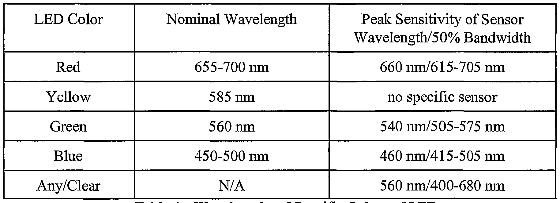
- Table 1 indicates a nominal wavelength emitted by several colors of standard LEDs 15 in addition to a peak sensitivity of sensor 10 according to a preferred embodiment of this invention.
- the peak sensitivity of sensor 10 is the wavelength at which sensor 10 generates the most current per light striking an active region of sensor 10.
- the 50% bandwidth entry is similar to a 3 dB point of an electronic filter. So light of a wavelength on the edge of the 50% bandwidth would produce half the current of the same amount of light at the peak sensitivity wavelength.
- two probes 40 are connected with respect to photosensitive semiconductor 20 and optical filter 30 for passing current from photosensitive semiconductor 20.
- Probes 40 are preferably slotted at one end to facilitate connection with respect to photosensitive semiconductor 20.
- probes 40 are metal probes such as part number PRP 2562X manufactured by QA Technology Company, Inc.
- probes 40 each include a 90° bend.
- probes 40 may be pre-formed into other configurations or may be bendable to permit forming into suitable configurations.
- Bias resistor 50 is preferably connected across probes 40 to provide an output voltage corresponding to an intensity of light of the target wavelength. Bias resistor 50 preferably creates the output voltage based upon the current generated by the target wavelength of light through sensor 10. Bias resistor 50 is preferably selected to create a voltage within a predetermined range depending upon the color to be verified. As a result of the described construction, sensor 10 provides an output voltage corresponding to a target wavelength corresponding to an appropriate color of LED 15 and blocks light outside of the target wavelength. According to a preferred embodiment of this invention, test system 60 is in communication with sensor 10 for converting the output voltage into pass/fail signal 65.
- Test system 60 may comprise an in-circuit tester such as those manufactured by Agilent, Genrad or Teradyne in combination with software suitable to translate the output of sensor 10 into pass/fail signal 65.
- Test system 60 may additionally include verification module 70 for determining whether the output voltage exceeds a predetermined minimum test voltage for the intensity of light of the target wavelength.
- test system 60 may further include warning signal 75 to indicate excessive ambient light between sensor 10 and LED 15. Warning signal 75 is useful for indicating whether the test conditions are optimized and insulated from contamination caused by excess ambient light.
- a method for verifying a color of LED 15 in printed circuit board 90 includes first positioning one or more sensors 10 on fixture board 80. Printed circuit board 90 is then preferably positioned within test fixture 80 so that sensor 10 is positioned directly adjacent LED 15.
- test fixture 80 includes bed 85 for accepting printed circuit board 90 and one or more sensors 10.
- Printed circuit board 90 is preferably positioned within bed 85 of test fixture 80.
- Test fixture 80 may further comprise power source 95 for turning on one or more LEDs 15.
- test fixture 80 includes baffles (not shown) or is otherwise configured, such as in a clamshell configuration, to block at least a portion of ambient light to printed circuit board 90.
- LED 15 is next turned on by powering up the entire printed circuit board 90 or isolating only LEDs 15 with power source 95. Once powered up, LED 15 is illuminated thus exposing sensor 10 to the color of LED 15.
- test system 60 is preferably in communication with sensor 10 and/or test fixture 80 and converts the output voltage generated by sensor 10 to pass/fail signal 65.
- the output voltage is sent from sensor 10 to test system 60 based upon the intensity of light of the target wavelength.
- test system 60 generates pass/fail signal 65 to indicate whether the correct LEDs 15 are in position and/or in operation.
- Such an analysis may include measuring a voltage across bias resistor 50 and comparing the voltage to predicted values for the color to be verified.
- Preferably such analysis is imbedded in test system 60 as configurable software.
- the software and/or test system 60 may be configured to include the steps of: (1) measuring a V on across sensor 10 when LED 15 is on; (2) measuring a N off across sensor 10 when LED 15 is off; (3) subtracting the V off from the V on to determine a nominal voltage; and (4) comparing the nominal voltage with a predetermined minimum voltage for the color to be verified.
- the following table provides actual values for measuring and verifying the color of particular LEDs 15.
- a red LED may produce enough light on the active region of the red sensor for a voltage of 450 mV to be developed across sensor 10.
- a yellow LED with the same light intensity might produce about 120 mV and a green or blue LED even less. So setting the test limit at 300 mV would guarantee a red LED with a minimum working intensity is installed in printed circuit board 90, also called a circuit card assembly.
- a green LED is used to verify that LED 15 is not red or blue.
- all variables must be optimized and fault insertion must be used to set the limits. Variations from lot to lot of LEDs 15 may require additional fine tuning of test system 60.
- a clear sensor may be used to detect both elements of a bi-color LED turning on. However, preferably one color is selected to detect fully and measuring a reduced signal for the other color.
- LEDs 15 are positioned so that a light emitting surface is either positioned on an edge of printed circuit board 90 and thus perpendicular to surface of printed circuit board 90, as shown in Figs. 1-3, or positioned in an interior area of printed circuit board 90 and thus parallel to surface of printed circuit board 90, as shown in Figs. 4 and 5.
- sensor 10 when a light emitting surface of LED 15 is perpendicular to printed circuit board 90, sensor 10 is positioned at least approximately 0.10" away from the light emitting surface and up to approximately 0.20" or more away from the light emitting surface of LED 15. Factors such as the strength of the light source, the intensity of the light source and the amount of ambient light may result in variations of a preferred position of sensor 10 relative to LED 15.
- a center of an active region of sensor 10, likely a center of optical filter 30, is preferably aligned with a center of a lens of LED 15.
- probes 40 are preferably not in a compression when positioning sensor 10 with respect to test fixture 80.
- sensor 10 when the light emitting surface of LED 15 is parallel to printed circuit board 90, sensor 10 is likewise positioned at least approximately 0.10" away from the light emitting surface of LED 15 and up to approximately 0.20" or more away from the light emitting surface of LED 15. Like in a parallel configuration, factors such as the strength of the light source, the intensity of the light source and the amount of ambient light may result in variations of a preferred position of sensor 10 relative to LED 15. Probes 40 according to this preferred embodiment are preferably configured so that an approximately 0.250" stroke probe sits above the board approximately 0.15" when engaged.
Landscapes
- Physics & Mathematics (AREA)
- Spectroscopy & Molecular Physics (AREA)
- General Physics & Mathematics (AREA)
- Condensed Matter Physics & Semiconductors (AREA)
- Electromagnetism (AREA)
- Engineering & Computer Science (AREA)
- Computer Hardware Design (AREA)
- Microelectronics & Electronic Packaging (AREA)
- Power Engineering (AREA)
- Spectrometry And Color Measurement (AREA)
- Investigating Materials By The Use Of Optical Means Adapted For Particular Applications (AREA)
- Led Devices (AREA)
- Testing, Inspecting, Measuring Of Stereoscopic Televisions And Televisions (AREA)
Abstract
Description
Claims
Priority Applications (6)
| Application Number | Priority Date | Filing Date | Title |
|---|---|---|---|
| CA002428690A CA2428690C (en) | 2000-11-13 | 2001-11-05 | Method and apparatus for verifying a color of an led in a printed circuit board |
| AU2002228854A AU2002228854A1 (en) | 2000-11-13 | 2001-11-05 | Method and apparatus for verifying a color of an led in a printed circuit board |
| MXPA03004223A MXPA03004223A (en) | 2000-11-13 | 2001-11-05 | Method and apparatus for verifying a color of an led in a printed circuit board. |
| EP01989975A EP1356309B1 (en) | 2000-11-13 | 2001-11-05 | Method and apparatus for verifying a color of a led in a printed circuit board |
| AT01989975T ATE462979T1 (en) | 2000-11-13 | 2001-11-05 | METHOD AND DEVICE FOR VERIFYING A COLOR OF AN LED IN A CIRCUIT BOARD |
| DE60141711T DE60141711D1 (en) | 2000-11-13 | 2001-11-05 | METHOD AND DEVICE FOR VERIFYING A COLOR OF AN LED IN A PCB |
Applications Claiming Priority (2)
| Application Number | Priority Date | Filing Date | Title |
|---|---|---|---|
| US09/712,371 US6490037B1 (en) | 2000-11-13 | 2000-11-13 | Method and apparatus for verifying a color of an LED in a printed circuit board |
| US09/712,371 | 2000-11-13 |
Publications (4)
| Publication Number | Publication Date |
|---|---|
| WO2002039414A2 true WO2002039414A2 (en) | 2002-05-16 |
| WO2002039414A3 WO2002039414A3 (en) | 2003-08-21 |
| WO2002039414B1 WO2002039414B1 (en) | 2004-04-29 |
| WO2002039414A9 WO2002039414A9 (en) | 2004-06-24 |
Family
ID=24861824
Family Applications (1)
| Application Number | Title | Priority Date | Filing Date |
|---|---|---|---|
| PCT/US2001/046922 WO2002039414A2 (en) | 2000-11-13 | 2001-11-05 | Method and apparatus for verifying a color of an led in a printed circuit board |
Country Status (8)
| Country | Link |
|---|---|
| US (1) | US6490037B1 (en) |
| EP (1) | EP1356309B1 (en) |
| AT (1) | ATE462979T1 (en) |
| AU (1) | AU2002228854A1 (en) |
| CA (1) | CA2428690C (en) |
| DE (1) | DE60141711D1 (en) |
| MX (1) | MXPA03004223A (en) |
| WO (1) | WO2002039414A2 (en) |
Families Citing this family (10)
| Publication number | Priority date | Publication date | Assignee | Title |
|---|---|---|---|---|
| US6623142B1 (en) * | 2002-02-15 | 2003-09-23 | Delphi Technologies, Inc. | Method and apparatus for correcting optical non-uniformities in a light emitting diode |
| US7064832B2 (en) * | 2003-02-26 | 2006-06-20 | Delaware Capital Formation, Inc. | Color and intensity measuring module for test of light emitting components by automated test equipment |
| US7023554B2 (en) * | 2003-11-14 | 2006-04-04 | Test Coach Corporation | Method and apparatus for determining a color and brightness of an LED in a printed circuit board |
| US7265822B2 (en) * | 2004-10-01 | 2007-09-04 | Test Coach Corporation | Method and apparatus for determining presence of a component in a printed circuit board |
| US20060214089A1 (en) * | 2005-03-22 | 2006-09-28 | An Byoung E | Method and apparatus for real time output monitoring of light sources and flexible sensitivity adjustment of light sensors |
| CN100573168C (en) * | 2005-04-21 | 2009-12-23 | 鸿富锦精密工业(深圳)有限公司 | The system and method for test computer panel LED light lamp and connecting line thereof |
| CN101424722B (en) * | 2007-10-31 | 2011-01-05 | 鸿富锦精密工业(深圳)有限公司 | LED test system for mainboard and method |
| JP5542303B2 (en) * | 2007-12-28 | 2014-07-09 | ソニー株式会社 | Light source system and display device |
| US10302496B2 (en) * | 2016-02-09 | 2019-05-28 | Nasa Solutions, Llc | Method and apparatus for determining presence and operation of a component in a printed circuit board |
| US10612978B2 (en) | 2018-03-01 | 2020-04-07 | International Business Machines Corporation | Light emitting diode color resolution testing |
Citations (3)
| Publication number | Priority date | Publication date | Assignee | Title |
|---|---|---|---|---|
| JPH03133183A (en) | 1989-10-18 | 1991-06-06 | Fujitsu Ltd | Testing equipment for light emitting diode array |
| US5381103A (en) | 1992-10-13 | 1995-01-10 | Cree Research, Inc. | System and method for accelerated degradation testing of semiconductor devices |
| JP2000223746A (en) | 1999-02-03 | 2000-08-11 | Rohm Co Ltd | Method and apparatus for inspecting resin packaged led |
Family Cites Families (8)
| Publication number | Priority date | Publication date | Assignee | Title |
|---|---|---|---|---|
| NL8400380A (en) * | 1984-02-07 | 1985-09-02 | Optische Ind De Oude Delft Nv | DEVICE FOR DETECTING COLOR DIFFERENCES. |
| US4611116A (en) * | 1984-02-21 | 1986-09-09 | Batt James E | Light emitting diode intensity tester |
| US4808815A (en) * | 1987-03-23 | 1989-02-28 | Genrad, Inc. | Apparatus for testing light-emitting devices using probe means having a preselected pattern arrangement |
| US4775640A (en) * | 1987-05-01 | 1988-10-04 | American Telephone And Telegraph Company | Electronic device test method and apparatus |
| JPH06101592B2 (en) * | 1989-08-31 | 1994-12-12 | 株式会社東芝 | Light emission output measuring device for semiconductor light emitting element |
| JP2740135B2 (en) * | 1995-02-17 | 1998-04-15 | 大成化工株式会社 | Simple absorbance meter |
| US6127783A (en) * | 1998-12-18 | 2000-10-03 | Philips Electronics North America Corp. | LED luminaire with electronically adjusted color balance |
| GB0002326D0 (en) * | 2000-02-01 | 2000-03-22 | Notionlight Limited | Circuit board component testing |
-
2000
- 2000-11-13 US US09/712,371 patent/US6490037B1/en not_active Expired - Lifetime
-
2001
- 2001-11-05 AT AT01989975T patent/ATE462979T1/en not_active IP Right Cessation
- 2001-11-05 EP EP01989975A patent/EP1356309B1/en not_active Expired - Lifetime
- 2001-11-05 WO PCT/US2001/046922 patent/WO2002039414A2/en not_active Application Discontinuation
- 2001-11-05 MX MXPA03004223A patent/MXPA03004223A/en active IP Right Grant
- 2001-11-05 CA CA002428690A patent/CA2428690C/en not_active Expired - Lifetime
- 2001-11-05 AU AU2002228854A patent/AU2002228854A1/en not_active Abandoned
- 2001-11-05 DE DE60141711T patent/DE60141711D1/en not_active Expired - Lifetime
Patent Citations (3)
| Publication number | Priority date | Publication date | Assignee | Title |
|---|---|---|---|---|
| JPH03133183A (en) | 1989-10-18 | 1991-06-06 | Fujitsu Ltd | Testing equipment for light emitting diode array |
| US5381103A (en) | 1992-10-13 | 1995-01-10 | Cree Research, Inc. | System and method for accelerated degradation testing of semiconductor devices |
| JP2000223746A (en) | 1999-02-03 | 2000-08-11 | Rohm Co Ltd | Method and apparatus for inspecting resin packaged led |
Also Published As
| Publication number | Publication date |
|---|---|
| CA2428690C (en) | 2009-01-27 |
| ATE462979T1 (en) | 2010-04-15 |
| US6490037B1 (en) | 2002-12-03 |
| EP1356309B1 (en) | 2010-03-31 |
| EP1356309A2 (en) | 2003-10-29 |
| WO2002039414B1 (en) | 2004-04-29 |
| CA2428690A1 (en) | 2002-05-16 |
| DE60141711D1 (en) | 2010-05-12 |
| AU2002228854A1 (en) | 2002-05-21 |
| WO2002039414A3 (en) | 2003-08-21 |
| WO2002039414A9 (en) | 2004-06-24 |
| MXPA03004223A (en) | 2004-12-02 |
Similar Documents
| Publication | Publication Date | Title |
|---|---|---|
| US7227639B2 (en) | Method and apparatus for determining a color and brightness of an LED in a printed circuit board | |
| US7064832B2 (en) | Color and intensity measuring module for test of light emitting components by automated test equipment | |
| US6490037B1 (en) | Method and apparatus for verifying a color of an LED in a printed circuit board | |
| US20070013772A1 (en) | In-circuit test fixture with integral vision inspection system | |
| US8178827B2 (en) | Universal LED testing device | |
| US20020089599A1 (en) | Illumination and image acquisition system | |
| US10302496B2 (en) | Method and apparatus for determining presence and operation of a component in a printed circuit board | |
| DE69836407D1 (en) | Arrangement for checking the signal voltage level accuracy in a digital test device | |
| US10094877B2 (en) | Method and apparatus for determining presence and operation of components in a printed circuit board | |
| US5432456A (en) | Connector installation GO/NO-GO test fixture | |
| US7265822B2 (en) | Method and apparatus for determining presence of a component in a printed circuit board | |
| US20020109830A1 (en) | Currency validator | |
| GB2364118A (en) | Circuit board component testing | |
| CN110244212B (en) | System and method for testing service life of organic light-emitting diode device and light measurement device | |
| JPH06267315A (en) | Linear lighting system and line image sensor inspecting device | |
| US20070275588A1 (en) | Isolated signal probe | |
| KR100830720B1 (en) | Optical Measuring Equipment Using Lightguide Ass'y And Optical Measuring Method | |
| JPH04133403U (en) | Probe card for laser trimming | |
| JP2005164300A (en) | Color sensor | |
| KR20020084742A (en) | Testing device for the Laser Diode | |
| EP0509129A3 (en) | Device for automatically adjusting and testing functions of colour component modules | |
| KR20040080787A (en) | Test apparatus of Print Circuit Board | |
| JPH01141360A (en) | Waveform observing device using optical fiber | |
| EP0386210A1 (en) | Method of and apparatus for testing optical sensor based control apparatus | |
| JPH02176537A (en) | Control device for electric car |
Legal Events
| Date | Code | Title | Description |
|---|---|---|---|
| AK | Designated states |
Kind code of ref document: A2 Designated state(s): AE AG AL AM AT AU AZ BA BB BG BR BY BZ CA CH CN CO CR CU CZ DE DK DM DZ EC EE ES FI GB GD GE GH GM HR HU ID IL IN IS JP KE KG KP KR KZ LC LK LR LS LT LU LV MA MD MG MK MN MW MX MZ NO NZ OM PH PL PT RO RU SD SE SG SI SK SL TJ TM TR TT TZ UA UG UZ VN YU ZA ZW |
|
| AL | Designated countries for regional patents |
Kind code of ref document: A2 Designated state(s): GH GM KE LS MW MZ SD SL SZ TZ UG ZW AM AZ BY KG KZ MD RU TJ TM AT BE CH CY DE DK ES FI FR GB GR IE IT LU MC NL PT SE TR BF BJ CF CG CI CM GA GN GQ GW ML MR NE SN TD TG |
|
| 121 | Ep: the epo has been informed by wipo that ep was designated in this application | ||
| WWE | Wipo information: entry into national phase |
Ref document number: PA/a/2003/004223 Country of ref document: MX Ref document number: 2428690 Country of ref document: CA |
|
| WWE | Wipo information: entry into national phase |
Ref document number: 2001989975 Country of ref document: EP |
|
| DFPE | Request for preliminary examination filed prior to expiration of 19th month from priority date (pct application filed before 20040101) | ||
| REG | Reference to national code |
Ref country code: DE Ref legal event code: 8642 |
|
| WWP | Wipo information: published in national office |
Ref document number: 2001989975 Country of ref document: EP |
|
| B | Later publication of amended claims |
Effective date: 20030110 |
|
| COP | Corrected version of pamphlet |
Free format text: PAGES 1/3-3/3, DRAWINGS, REPLACED BY NEW PAGES 1/4-4/4; DUE TO LATE TRANSMITTAL BY THE RECEIVING OFFICE |
|
| NENP | Non-entry into the national phase |
Ref country code: JP |
|
| WWW | Wipo information: withdrawn in national office |
Ref document number: JP |