WO2002003513A1 - Blue laser based on interactions in fiber - Google Patents
Blue laser based on interactions in fiber Download PDFInfo
- Publication number
- WO2002003513A1 WO2002003513A1 PCT/US2001/018987 US0118987W WO0203513A1 WO 2002003513 A1 WO2002003513 A1 WO 2002003513A1 US 0118987 W US0118987 W US 0118987W WO 0203513 A1 WO0203513 A1 WO 0203513A1
- Authority
- WO
- WIPO (PCT)
- Prior art keywords
- fiber
- radiation
- microns
- wavelength
- fiber device
- Prior art date
Links
Classifications
-
- H—ELECTRICITY
- H01—ELECTRIC ELEMENTS
- H01S—DEVICES USING THE PROCESS OF LIGHT AMPLIFICATION BY STIMULATED EMISSION OF RADIATION [LASER] TO AMPLIFY OR GENERATE LIGHT; DEVICES USING STIMULATED EMISSION OF ELECTROMAGNETIC RADIATION IN WAVE RANGES OTHER THAN OPTICAL
- H01S5/00—Semiconductor lasers
- H01S5/30—Structure or shape of the active region; Materials used for the active region
-
- H—ELECTRICITY
- H01—ELECTRIC ELEMENTS
- H01S—DEVICES USING THE PROCESS OF LIGHT AMPLIFICATION BY STIMULATED EMISSION OF RADIATION [LASER] TO AMPLIFY OR GENERATE LIGHT; DEVICES USING STIMULATED EMISSION OF ELECTROMAGNETIC RADIATION IN WAVE RANGES OTHER THAN OPTICAL
- H01S3/00—Lasers, i.e. devices using stimulated emission of electromagnetic radiation in the infrared, visible or ultraviolet wave range
- H01S3/05—Construction or shape of optical resonators; Accommodation of active medium therein; Shape of active medium
- H01S3/06—Construction or shape of active medium
- H01S3/063—Waveguide lasers, i.e. whereby the dimensions of the waveguide are of the order of the light wavelength
- H01S3/067—Fibre lasers
-
- G—PHYSICS
- G02—OPTICS
- G02F—OPTICAL DEVICES OR ARRANGEMENTS FOR THE CONTROL OF LIGHT BY MODIFICATION OF THE OPTICAL PROPERTIES OF THE MEDIA OF THE ELEMENTS INVOLVED THEREIN; NON-LINEAR OPTICS; FREQUENCY-CHANGING OF LIGHT; OPTICAL LOGIC ELEMENTS; OPTICAL ANALOGUE/DIGITAL CONVERTERS
- G02F1/00—Devices or arrangements for the control of the intensity, colour, phase, polarisation or direction of light arriving from an independent light source, e.g. switching, gating or modulating; Non-linear optics
- G02F1/35—Non-linear optics
- G02F1/37—Non-linear optics for second-harmonic generation
-
- H—ELECTRICITY
- H01—ELECTRIC ELEMENTS
- H01S—DEVICES USING THE PROCESS OF LIGHT AMPLIFICATION BY STIMULATED EMISSION OF RADIATION [LASER] TO AMPLIFY OR GENERATE LIGHT; DEVICES USING STIMULATED EMISSION OF ELECTROMAGNETIC RADIATION IN WAVE RANGES OTHER THAN OPTICAL
- H01S3/00—Lasers, i.e. devices using stimulated emission of electromagnetic radiation in the infrared, visible or ultraviolet wave range
- H01S3/05—Construction or shape of optical resonators; Accommodation of active medium therein; Shape of active medium
- H01S3/06—Construction or shape of active medium
- H01S3/063—Waveguide lasers, i.e. whereby the dimensions of the waveguide are of the order of the light wavelength
- H01S3/067—Fibre lasers
- H01S3/06708—Constructional details of the fibre, e.g. compositions, cross-section, shape or tapering
- H01S3/06716—Fibre compositions or doping with active elements
-
- H—ELECTRICITY
- H01—ELECTRIC ELEMENTS
- H01S—DEVICES USING THE PROCESS OF LIGHT AMPLIFICATION BY STIMULATED EMISSION OF RADIATION [LASER] TO AMPLIFY OR GENERATE LIGHT; DEVICES USING STIMULATED EMISSION OF ELECTROMAGNETIC RADIATION IN WAVE RANGES OTHER THAN OPTICAL
- H01S3/00—Lasers, i.e. devices using stimulated emission of electromagnetic radiation in the infrared, visible or ultraviolet wave range
- H01S3/05—Construction or shape of optical resonators; Accommodation of active medium therein; Shape of active medium
- H01S3/06—Construction or shape of active medium
- H01S3/063—Waveguide lasers, i.e. whereby the dimensions of the waveguide are of the order of the light wavelength
- H01S3/067—Fibre lasers
- H01S3/06708—Constructional details of the fibre, e.g. compositions, cross-section, shape or tapering
- H01S3/0672—Non-uniform radial doping
-
- H—ELECTRICITY
- H01—ELECTRIC ELEMENTS
- H01S—DEVICES USING THE PROCESS OF LIGHT AMPLIFICATION BY STIMULATED EMISSION OF RADIATION [LASER] TO AMPLIFY OR GENERATE LIGHT; DEVICES USING STIMULATED EMISSION OF ELECTROMAGNETIC RADIATION IN WAVE RANGES OTHER THAN OPTICAL
- H01S3/00—Lasers, i.e. devices using stimulated emission of electromagnetic radiation in the infrared, visible or ultraviolet wave range
- H01S3/05—Construction or shape of optical resonators; Accommodation of active medium therein; Shape of active medium
- H01S3/06—Construction or shape of active medium
- H01S3/063—Waveguide lasers, i.e. whereby the dimensions of the waveguide are of the order of the light wavelength
- H01S3/067—Fibre lasers
- H01S3/06708—Constructional details of the fibre, e.g. compositions, cross-section, shape or tapering
- H01S3/06729—Peculiar transverse fibre profile
-
- H—ELECTRICITY
- H01—ELECTRIC ELEMENTS
- H01S—DEVICES USING THE PROCESS OF LIGHT AMPLIFICATION BY STIMULATED EMISSION OF RADIATION [LASER] TO AMPLIFY OR GENERATE LIGHT; DEVICES USING STIMULATED EMISSION OF ELECTROMAGNETIC RADIATION IN WAVE RANGES OTHER THAN OPTICAL
- H01S3/00—Lasers, i.e. devices using stimulated emission of electromagnetic radiation in the infrared, visible or ultraviolet wave range
- H01S3/09—Processes or apparatus for excitation, e.g. pumping
- H01S3/091—Processes or apparatus for excitation, e.g. pumping using optical pumping
- H01S3/094—Processes or apparatus for excitation, e.g. pumping using optical pumping by coherent light
- H01S3/094003—Processes or apparatus for excitation, e.g. pumping using optical pumping by coherent light the pumped medium being a fibre
-
- H—ELECTRICITY
- H01—ELECTRIC ELEMENTS
- H01S—DEVICES USING THE PROCESS OF LIGHT AMPLIFICATION BY STIMULATED EMISSION OF RADIATION [LASER] TO AMPLIFY OR GENERATE LIGHT; DEVICES USING STIMULATED EMISSION OF ELECTROMAGNETIC RADIATION IN WAVE RANGES OTHER THAN OPTICAL
- H01S3/00—Lasers, i.e. devices using stimulated emission of electromagnetic radiation in the infrared, visible or ultraviolet wave range
- H01S3/14—Lasers, i.e. devices using stimulated emission of electromagnetic radiation in the infrared, visible or ultraviolet wave range characterised by the material used as the active medium
- H01S3/16—Solid materials
- H01S3/1601—Solid materials characterised by an active (lasing) ion
- H01S3/1603—Solid materials characterised by an active (lasing) ion rare earth
- H01S3/1611—Solid materials characterised by an active (lasing) ion rare earth neodymium
Definitions
- Nd:YAG lasers operating at 1064 nm.
- the output of the laser is frequency doubled with a nonlinear crystal to 532 nm.
- the frequency-doubled output then pumps an OPO.
- One of the OPO output wavelengths is then summed with the 532-nm light to create the blue.
- Nd:YAG lasers require water-cooling and resonator structures, which add to the complexity, bulk and cost of the system.
- the apparatus generally comprises a light-generating fiber device optically coupled to an optical harmonic generator.
- the fiber device produces radiation at a power level sufficient to operate the optical harmonic generator.
- the optical harmonic generator increases a frequency of the radiation to produce a blue output radiation.
- the fiber device may be an oscillator or an amplifier, such as a Neodymium-doped cladding-pumped fiber amplifier.
- the fiber device may be pumped by a high intensity pump source to enhance the gain of radiation having a harmonic that is blue.
- the pump power preferably remains above 50 Watts/mm 2 along substantially the entire length of the fiber.
- the power of pumping radiation is preferably greater than about 100 Watts/mm 2 and more preferably, about 500 Watts/mm 2 or greater at a fiber entrance depending on the pumping configuration.
- an oscillator may be optionally coupled to the fiber amplifier.
- the oscillator produces source radiation.
- the fiber amplifier amplifies the radiation produced by the oscillator.
- Suitable oscillators include mode locked lasers based on transitions in Nd: Glass, Nd:Vanadate, Nd:YLF, and other Nd materials and pulsed semiconductor lasers .
- the fiber device typically produces infrared radiation having a frequency with a harmonic that falls in the blue portion of the visible spectrum.
- the optical harmonic generator generates blue light from the infrared light by a non-linear harmonic generation process.
- the fiber device may include means to suppress gain of radiation having harmonics that are not blue. Such means include dopants, fiber gratings, and dichroic mirrors. In a specific embodiment, the gain suppression means suppresses gain at 1.05 ⁇ m without suppressing gain at 0.91 ⁇ m.
- a first alternative means for optical gain suppression includes a fiber having a core surrounded by a cladding with a tunnel cladding disposed between the cladding and the core. Light of an undesired wavelength tunnels out of the core along the length of the fiber. The fiber thus has no bound modes at the undesired wavelength.
- a second alternative means for optical gain suppression includes a fiber that has been bent to a bend radius such that wavelength dependent losses caused by the bending attenuate radiation of the undesired wavelength.
- the fiber device and blue laser apparatus find application as light sources for three-color light displays.
- Light sources based on the embodiments of the present invention are capable of producing blue light at an output power of order 1 watt or more.
- Fig. 1 depicts a chromaticity diagram, depicting color location
- Fig. 2A depicts a simplified schematic diagram of a blue laser according to a first embodiment of the present invention
- Fig. 2B depicts cross sectional schematic diagram of a fiber used in the laser of Fig. 2A
- Fig. 3A depicts a refractive index profile of a conventional fiber
- Figs. 3B-3C depict refractive index profiles for rejecting undesired wavelengths from the core of a fiber according to an embodiment of the present invention
- Fig. 4A depicts attenuation versus bend wavelength for a coiled fiber
- Fig. 4B depicts an embodiment of a blue laser source incorporating a coiled fiber to suppress gain at an undesired wavelength
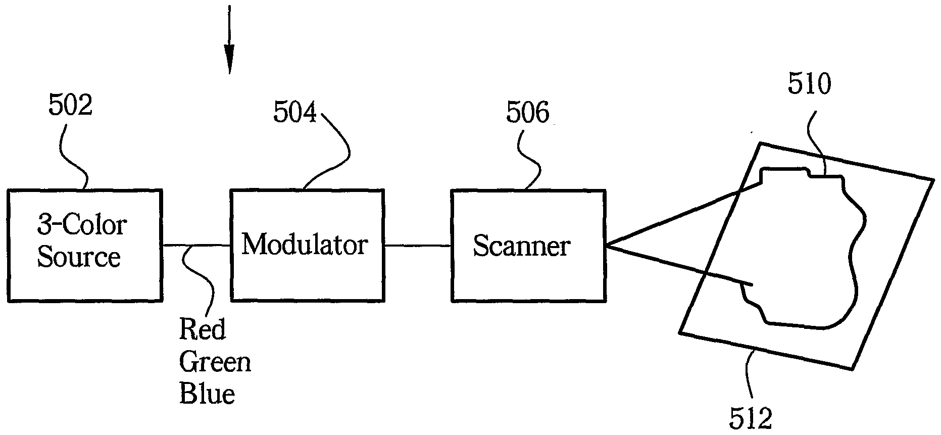
- Fig. 5 depicts a simplified schematic diagram of a display system according to a fourth embodiment of the present invention .
- blue light generally refers to electromagnetic radiation having a frequency of between about 6.7X10 14 Hz and 6.3X10 14 Hz (about
- Green light refers to radiation having a frequency of between about 5.9X10 14 Hz and
- Red light refers to radiation having a frequency of between about 4.8X10 14 Hz and 4.2X10 14 Hz (about 620 to 720 nm wavelength in vacuum) .
- Fig. 2A depicts a simplified schematic diagram of a blue laser apparatus according to a first embodiment of the present invention.
- the laser 200 generally comprises a Neodymium-doped cladding-pumped light-generating fiber device 202 optically coupled to a harmonic generator 220.
- the fiber device 202 may include a fiber oscillator, a fiber amplifier or both.
- the harmonic generator 220 generates a second or higher order harmonic of a source radiation 205 from the fiber device 202.
- the source radiation 205 is characterized by a wavelength- in vacuum corresponding to the color blue .
- the fiber device 202 comprises a fiber amplifier 210.
- the fiber amplifier 210 receives optical power in the form of source radiation 201 from an oscillator 230.
- the fiber amplifier 210 amplifies the optical power from the oscillator 230 to a level on the order of 1 watt or greater.
- the harmonic generator 220 may, for example, be a second-harmonic generator that doubles the frequency of the output of the amplifier 210 to produce blue output radiation 203.
- the blue radiation is preferably characterized by a wavelength in vacuum of between about 440 nm and about 460 nm.
- harmonic generator 220 may generate higher order harmonics of the source radiation 201 such as third-harmonics, etc. to produce blue radiation.
- the fiber amplifier 210 generally comprises an optical fiber 212 having a core 214 made of Neodymium doped glass.
- Fig. 2B depicts cross sectional schematic diagrams of the optical fiber 212.
- the fiber 212 generally comprises the core 214 surrounded by a cladding 217 including inner and outer cladding layers 216 and 218 respectively.
- the cladding layer 216 is optically coupled to a pump source 240.
- the pump source 240 may comprise one or more high-power pump diodes, for example, at a wavelength near 0.80 microns. Because of the three-level nature of the transition in Nd: Glass, the pump source 240 preferably produces pumping radiation 205 having an intensity that is a substantial fraction of a saturation intensity of the pumped transition, e.g. about 500 Watts/mm 2 . Such a pump source 240 is generally referred to herein as a high-brightness pump source .
- core 214 is preferably a single-mode core surrounded by a multi-mode inner cladding layer 216 which, in turn, is surrounded by outer cladding layer 218.
- the core 214 is typically doped with Neodymium (Nd) .
- Nd Neodymium
- a relatively high- power multimode pumping radiation signal 205 launched into the cladding 217 from the pump source is substantially confined and guided within the multi-mode cladding layer.
- Pumping radiation 205 propagates along the multi-mode inner cladding layer 216 criss-crossing the core 214.
- the Nd doped core 214 absorbs energy from the pumping radiation 205.
- Neodymium glass is known to have gain at a wavelength of 0.91 microns, but its gain at 1.05 microns is higher.
- Gain- suppression means at wavelengths having second harmonics that are not blue may be necessary, to keep parasitic oscillation at these wavelengths from extracting all the power from the amplifier 210.
- a first condition is for fiber 212 to have a distributed loss means that attenuates the 1.05 micron radiation from the high gain, undesired, long-wavelength transition much more than they attenuate the radiation from the desired, short wavelength transition.
- a second condition is that the intensity of the pumping radiation 205 at a wavelength near 800 nm be relatively high.
- the pump intensity preferably remains above 50 Watts /mm 2 along substantially the entire length of the fiber.
- the power of pumping radiation is preferably about 500 Watts/mm 2 or greater at a fiber entrance 207 if the pump radiation 205 passes once through the fiber 212.
- the minimum required pump intensity may be reduced to about 250 Watts/mm 2 if the pump radiation 205 exiting at a far end 209 of the fiber 212 is retroreflected so that it returns to the fiber 212.
- the intensity of pump radiation 205 may also be reduced if, for example, identical pumps are used at both ends of the fiber 212.
- the pump sources e.g. pump source 240 produce sufficient pump power that pump radiation 205 has an intensity of 50 Watts/mm 2 or greater inside the fiber 212 and an intensity greater than or equal to 100 Watts /mm 2 at the entrance to the fiber 212.
- Pumping intensities at levels greater than or equal to about 100 Watts/mm 2 have only recently become available.
- One pump source commonly used for diode pumping is an SDL-3460-P6 diode from SDL of San Jose, California. This pump source provides 16 Watts of power from a 0.6 mm diameter aperture. The pump intensity, i.e. the power divided by the aperture area is equal to about 57 Watts/mm 2 . This is generally inadequate for pumping the short wavelength transition of Nd: glass fiber, even with double ended pumping and suppression of the 1.05 micron transition. A newer design of fiber pump is available from LIMO of Dortmund, Germany. This diode source has a power of about 25 Watts from a 0.2 mm diameter fiber. The corresponding intensity is about 795 Watts/mm 2 . This is more than adequate to pump the short-wavelength transition of Nd: glass, even with single-ended pumping.
- the cladding 217 may include dopants that absorb radiation emitted by a 4 F 3/2 to I 11/2 atomic transition corresponding to a wavelength in vacuum of 1.05 microns for Neodymium glass and 1.06 microns for Nd:YAG.
- the dopants are also transparent to radiation emitted by a 4 F 3/2 to 4 I 9/2 atomic transition corresponding to 0.91 microns in Neodymium glass and 0.946 microns in Nd:YAG.
- dopants include ions such as Yb 3+ , Dy 3+ , Pr 3+ , Tm 2+ and Sm 3+ and V 3+ .
- gain at undesired wavelengths may be suppressed by means of gratings or mirrors.
- fiber 212 may have an index of refraction n that varies periodically along its length to form gratings .
- the gratings can reflect certain wavelengths of light out of the fiber while transmitting others.
- maxima in n are typically separated by a distance of approximately one-half the wavelength of undesired light in the fiber.
- the gratings are usually aligned at a non-normal incidence with respect to the fiber axis. Such gratings reject the undesired wavelengths from the core 214 of fiber 212.
- Fiber 212 may also include dichroic mirrors coupled to the ends of the fibers.
- the mirrors transmit wavelengths in an undesired range, e.g. 1.05 microns, while reflecting other wavelengths, e.g. 0.91 microns back into the fiber.
- FIG. 3A depicts a graph 300 of refractive index n versus radial distance r from the center of a typical optical fiber.
- the core region 302 typically has a higher refractive index than the cladding region 304. Total internal reflection takes place at the interface 306 between the core region 302 and the cladding region 304.
- a fiber has a core region 312 surrounded by a tunnel cladding region 313.
- a cladding region 314 surrounds the tunnel cladding 313 and core regions 312.
- the core is characterized by -' a refractive index n beauc_ore and a radius r flickc.
- the cladding region 314 is characterized by a refractive index n cl and a thickness t cl .
- the tunnel cladding region 313 is characterized by a refractive index n # and a thickness t' .
- n / ⁇ n cl ⁇ n core . ⁇ Such a refractive index profile is sometimes referred to as a "W" profile.
- the propagation of radiation in fibers having such profiles is described in detail by Michael Monerie in "Propagation in Doubly Clad Single-Mode Fibers", IEEE Journal of Quantum Electronics QE-18 (1982) p. 525, which is incorporated herein by reference, and references therein. If the values of n core , n cl , n 7 , r c , t cl and t ' are chosen such that an average squared index of refraction (n 2 (r))
- tunnel cladding region 313 is thick enough that
- a specific embodiment of a practical application of this principle utilizes a triply clad fiber illustrated by the refractive index profile 320 of Fig. 3C.
- the fiber generally comprises a core region 322 surrounded by a tunnel cladding region 323.
- a pump cladding region 324 surrounds the core 322 and tunnel cladding 323 regions.
- An outer cladding region 326 surrounds the core 322, tunnel cladding 323, and pump cladding
- the core is characterized by a refractive index n oor ⁇ an ⁇ - a r a-d.ius r c .
- the tunnel cladding region 323 is characterized by a refractive index n' and a thickness t ' .
- the pump cladding region 324 is characterized by a refractive index npc and a thickness tpc .
- the outer cladding is characterized by a an index of refraction noc and a thickness toe.
- the outer cladding may be surrounded by air having an index of refraction of about 1.0.
- n / ⁇ n tJC ⁇ n cora and n oc ⁇ n pc Such a configuration allows the undesired radiation to tunnel out of the core region 322.
- the radius r pc is typically greater than a few undesired wavelengths .
- FIG. 4A depicts a graph 400 of attenuation versus wavelength ⁇ for a coiled
- a coiled fiber may be engineered to attenuate 1050 nm (i.e. 1.05 micron) radiation but not 910 nm (i.e. 0.91 micron) radiation.
- Fig. 4B depicts an exemplary embodiment of a blue laser apparatus incorporating a coiled fiber to suppress optical gain at an undesired wavelength.
- the apparatus generally comprises a cladding-pumped fiber device 420.
- the fiber device 420 generally comprises an optical fiber 422 coiled around a mandrel of radius R.
- the radius of the mandrel 424 determines a bend radius of the fiber 422 for suppression of gain at an undesired wavelength, e.g. 1050 nm, as described above.
- R is typically of order 10 mm. Attenuation of radiation by bending optical fibers is discussed in detail by Sakai et al . in Applied Optics 17 (1978) p.
- a pump 410 provides pump radiation for the fiber device 420.
- the pump 410 is optically coupled to a cladding of the fiber 422 to provide pumping as described above with respect to Fig. 2B .
- An optional source 412 provides radiation to a core of the fiber 422.
- the fiber device 420 may be coupled to a harmonic generator 430 to produce blue radiation, e.g., by doubling 910 nm infrared radiation.
- the harmonic generator 220 typically comprises a non-linear crystal including a material such as Lithium Niobate (LiNb0 3 ) , Lithium Tantalate (LiTa0 3 ) , Lithium Borate (LiB0 3 ) , Potassium Niobate, periodically poled lithium niobate (PPLN) , periodically poled lithium tantalate (PPLT) MgO:PPLN, KTP , PPKTP, RTA, BBO, or PPRTA.
- the harmonic generator 220 may be a second-harmonic generator that interacts with two photons of the source radiation 201 to produce a single photon of output radiation 203.
- the output radiation 203 will have a wavelength of 455 nm, which the eye senses as blue.
- a given piece of non-linear crystal has a characteristic frequency-doubling coefficient in units of % per Watt of input power. Generally, the higher the input power, the higher the conversion efficiency.
- the power of output radiation 203 goes as the square of the power of input source radiation 201 up to a point were the input is significantly depleted.
- the crystalline axes of the material comprising second-harmonic generator 220 must be in the right orientation, the crystal must be at the right temperature, the crystal must not damage under high input power.
- non-linear crystals may also be used as third-harmonic generators to triple the frequency of source radiation 201, or as higher order harmonic generators .
- the fiber device 202 includes a fiber amplifier, such as fiber amplifier 210 and the amplifier is coupled to an oscillator, such as oscillator 230.
- an oscillator such as oscillator 230.
- One constraint is that the oscillator must provide source radiation 201 at the correct wavelength because
- the amplifier 210 generally does not shift wavelengths.
- the average power of the radiation in the amplifier 210 is preferably on the order of 10 mW or greater so that the amplifier 210 operates stably and with low noise.
- the oscillator must have a low enough duty cycle so that the peak power after amplification is high enough for efficient non-linear conversion in the harmonic generator 220.
- the oscillator 230 may be, for example, a short-pulse oscillator that produces infrared radiation at a wavelength near 0.91 microns for Neodymium-doped fiber amplifier 210 and a few milliwatts of power.
- oscillator 230 include pulsed, low-duty-cycle semiconductor lasers and mode-locked Nd: Glass or crystal lasers.
- Low duty cycle, short pulse (e.g. ⁇ 100 ps) oscillators are typically used to provide sufficient peak power for existing harmonic generators.
- One oscillator type is a mode-locked neodymium bulk crystalline or glass laser operating at the same transition as the Nd:Glass fiber 212.
- Mode-locked lasers can conveniently have a ratio of peak power to average power of 1000. Thus an amplified signal with a 1 Watt average power would have a 1 kilowatt peak power, which is adequate for efficient nonlinear conversion.
- mode-locked lasers have been difficult to maintain and operate. The typically require complex electronics and tight mechanical tolerances.
- Such "passively mode-locked” typically use Nd:YLF, Nd:Yttrium Vanadate, or Nd:Glass.
- Such a "passively mode-locked” laser may be used as oscillator 230.
- Another possible type of device for oscillator 230 is a modulated semiconductor laser.
- Semiconductor lasers with a wavelength of 910 nm are available. Some of these lasers can be electrically pulsed to provide pulses as short as 100 psec (10 ⁇ 10 sec) , while maintaining an average power near 1 mW and peak power near 100 mW. Such a power level and duty cycle are
- a semiconductor laser may be externally modulated using, for example, a waveguide modulator .
- Waveguide modulators may be faster than electrical pulsing of the semiconductor laser itself. Furthermore, waveguide modulators may provide better stability.
- a blue laser of the type described above with respect to Figs. 2A and 2B can be incorporated into a three-color light source according to a second embodiment of the present invention.
- a blue laser source of the type described above with respect to Figs. 2A and 2B can be incorporated into a three-color light source according to a second embodiment of the present invention.
- the following description describes a specific embodiment that uses such a source to generate blue light, other blue laser sources may be used without loss of generality.
- Fig. 5 depicts a simplified schematic diagram of a display system 500 according to a fourth embodiment of the present invention.
- the system 500 generally comprises a three color source 502, and a scanning means 506 optically coupled to the source 502.
- the source 502 produces blue laser light as described above.
- the source 502 may produce green and red light by any suitable means .
- the source 502 may alternatively produce other color combinations of three or more colors, including blue .
- the modulating means 504 modulates the intensities of the red, green, and blue light to produce different colors.
- the light emerging from the source 502 may be split into three separate beams, each beam corresponding to a different color, through the use of wavelength selective beam
- the scanner 506 produces an image 510 from the modulated output beam 508.
- the scanner may be coupled to the source 502 or the modulator 504.
- the scanner may raster scan the output beam 508 across a screen 512 in two dimensions in a manner having features in common with conventional video image generation.
- the modulator 504 modulates the power of a beam of output radiation
- a hi-speed scanning system rasters the beam across a screen.
- the scanner 506 may produce an image line-by-line.
- a line-by-line system creates a whole "line" of the display at a time, by spreading the light over a linear array of modulators. This line is then scanned across the screen 512 in only one dimension.
- Embodiments of the present invention that utilize fiber amplifiers can be much more efficient than competing techniques, since fiber amplifiers are very efficient. Temperature of pump diodes can be less critical since fiber amplifiers have loose tolerances on pump wavelength. The embodiments of the present invention can be implemented without water cooling since the more efficient system dissipates less heat and the tolerant pump wavelength specification generally requires less precise temperature control. Furthermore, fiber based systems can be made more compact since fiber can be wound up into a small volume.
- An apparatus for producing blue light comprising: a) a neodymium-doped cladding-pumped fiber device for generating a first radiation; and b) an optical harmonic generator optically coupled to the fiber device for increasing a frequency of the radiation to produce a blue output radiation.
Abstract
Description
Claims


Priority Applications (3)
| Application Number | Priority Date | Filing Date | Title |
|---|---|---|---|
| DE60126098T DE60126098T2 (en) | 2000-06-29 | 2001-06-12 | BLUE LASER BASED ON INTERACTIONS IN A FIBER |
| JP2002507484A JP4180364B2 (en) | 2000-06-29 | 2001-06-12 | Blue laser based on interaction in fiber |
| EP01944485A EP1307953B1 (en) | 2000-06-29 | 2001-06-12 | Blue laser based on interactions in fiber |
Applications Claiming Priority (2)
| Application Number | Priority Date | Filing Date | Title |
|---|---|---|---|
| US09/608,442 | 2000-06-29 | ||
| US09/608,442 US6614815B1 (en) | 2000-06-29 | 2000-06-29 | Blue laser based on interactions in fiber |
Publications (2)
| Publication Number | Publication Date |
|---|---|
| WO2002003513A1 true WO2002003513A1 (en) | 2002-01-10 |
| WO2002003513A8 WO2002003513A8 (en) | 2002-03-21 |
Family
ID=24436523
Family Applications (1)
| Application Number | Title | Priority Date | Filing Date |
|---|---|---|---|
| PCT/US2001/018987 WO2002003513A1 (en) | 2000-06-29 | 2001-06-12 | Blue laser based on interactions in fiber |
Country Status (8)
| Country | Link |
|---|---|
| US (1) | US6614815B1 (en) |
| EP (1) | EP1307953B1 (en) |
| JP (1) | JP4180364B2 (en) |
| KR (1) | KR100813354B1 (en) |
| CN (1) | CN1218447C (en) |
| AT (1) | ATE352114T1 (en) |
| DE (1) | DE60126098T2 (en) |
| WO (1) | WO2002003513A1 (en) |
Families Citing this family (17)
| Publication number | Priority date | Publication date | Assignee | Title |
|---|---|---|---|---|
| US20050041702A1 (en) * | 1997-03-21 | 2005-02-24 | Imra America, Inc. | High energy optical fiber amplifier for picosecond-nanosecond pulses for advanced material processing applications |
| CA2349912A1 (en) * | 2000-07-07 | 2002-01-07 | Heidelberger Druckmaschinen Aktiengesellschaft | Setting an image on a printing plate using ultrashort laser pulses |
| US7039076B2 (en) * | 2001-08-10 | 2006-05-02 | Jds Uniphase Corporation | Fiber amplifier system for producing visible light |
| US7116687B2 (en) * | 2003-09-12 | 2006-10-03 | Jds Uniphase Corporation | High repetition rate passively Q-switched laser for blue laser based on interactions in fiber |
| JP2006019490A (en) * | 2004-07-01 | 2006-01-19 | Toyoda Mach Works Ltd | Fiber laser oscillator |
| WO2006006701A1 (en) * | 2004-07-15 | 2006-01-19 | Matsushita Electric Industrial Co., Ltd. | Coherent light source and optical device using the same |
| CN100538503C (en) * | 2004-11-08 | 2009-09-09 | 松下电器产业株式会社 | Used the image projection apparatus of coherent source |
| US20070110379A1 (en) * | 2005-11-14 | 2007-05-17 | Applied Materials, Inc. Legal Department | Pinch waveguide |
| WO2007059129A2 (en) * | 2005-11-14 | 2007-05-24 | Applied Materials, Inc. | Pinch waveguide |
| WO2012047218A1 (en) * | 2010-10-07 | 2012-04-12 | Ipg Photonics Corporation | High power neodymium fiber lasers and amplifiers |
| US9716365B2 (en) | 2013-03-22 | 2017-07-25 | Ipg Photonics Corporation | High power neodymium fiber lasers and amplifiers |
| CN104362497A (en) * | 2014-11-20 | 2015-02-18 | 山东海富光子科技股份有限公司 | Single-frequency blue-green light source based on 930 nm single-frequency fiber laser unit |
| CN107621672A (en) * | 2016-07-14 | 2018-01-23 | 中国兵器装备研究院 | A kind of integrated high power cladding light stripper |
| DE102017109954B3 (en) * | 2017-05-09 | 2018-05-24 | Active Fiber Systems Gmbh | Short pulse laser with high temporal contrast |
| CN110678790B (en) * | 2017-06-02 | 2021-01-26 | 康普技术有限责任公司 | Concentric optical fibers for space division multiplexed optical communications and methods of use thereof |
| CN111596408B (en) * | 2020-05-25 | 2022-01-25 | 光惠(上海)激光科技有限公司 | High-power fiber laser indication light protection device and implementation method thereof |
| CN111711061A (en) * | 2020-06-29 | 2020-09-25 | 华南理工大学 | Dual-wavelength all-fiber laser |
Citations (1)
| Publication number | Priority date | Publication date | Assignee | Title |
|---|---|---|---|---|
| US5867305A (en) * | 1996-01-19 | 1999-02-02 | Sdl, Inc. | Optical amplifier with high energy levels systems providing high peak powers |
Family Cites Families (22)
| Publication number | Priority date | Publication date | Assignee | Title |
|---|---|---|---|---|
| US4764933A (en) * | 1986-08-15 | 1988-08-16 | Stanford University | Diode pumped low doped Nd 3+ glass laser |
| US5056888A (en) | 1989-07-17 | 1991-10-15 | Minnesota Mining And Manufacturing Company | Single-mode, single-polarization optical fiber |
| US5488626A (en) | 1991-01-14 | 1996-01-30 | Light Age, Inc. | Method of and apparatus for pumping of transition metal ion containing solid state lasers using diode laser sources |
| JP3211448B2 (en) | 1993-01-27 | 2001-09-25 | ソニー株式会社 | Laser light source device |
| US5422897A (en) | 1994-01-28 | 1995-06-06 | British Telecommunications Public Limited Company | Two-stage mono-mode optical fibre laser |
| US5659558A (en) | 1995-03-06 | 1997-08-19 | Matsushita Electric Industrial Co., Ltd. | Short-wavelength laser element doped with rare earth ions, optical amplifier doped with rare earth ions, and wavelength converter doped with rare earth ions |
| US5651019A (en) | 1995-04-28 | 1997-07-22 | The United States Of America As Represented By The Secretary Of The Navy | Solid-state blue laser source |
| US5745284A (en) | 1996-02-23 | 1998-04-28 | President And Fellows Of Harvard College | Solid-state laser source of tunable narrow-bandwidth ultraviolet radiation |
| US5909306A (en) | 1996-02-23 | 1999-06-01 | President And Fellows Of Harvard College | Solid-state spectrally-pure linearly-polarized pulsed fiber amplifier laser system useful for ultraviolet radiation generation |
| US6021141A (en) * | 1996-03-29 | 2000-02-01 | Sdl, Inc. | Tunable blue laser diode |
| US5912910A (en) * | 1996-05-17 | 1999-06-15 | Sdl, Inc. | High power pumped mid-IR wavelength systems using nonlinear frequency mixing (NFM) devices |
| US6212310B1 (en) * | 1996-10-22 | 2001-04-03 | Sdl, Inc. | High power fiber gain media system achieved through power scaling via multiplexing |
| US5880877A (en) * | 1997-01-28 | 1999-03-09 | Imra America, Inc. | Apparatus and method for the generation of high-power femtosecond pulses from a fiber amplifier |
| US5974059A (en) | 1997-03-04 | 1999-10-26 | 3M Innovative Properties Company | Frequency doubled fiber laser |
| US5892615A (en) | 1997-03-17 | 1999-04-06 | Sdl, Inc. | Output power enhancement in optical fiber lasers |
| US5999548A (en) * | 1997-06-18 | 1999-12-07 | Nippon Telegraph And Telephone Corporation | White optical pulse source and applications |
| US5818630A (en) * | 1997-06-25 | 1998-10-06 | Imra America, Inc. | Single-mode amplifiers and compressors based on multi-mode fibers |
| US5966391A (en) | 1997-06-27 | 1999-10-12 | Mcdonnell Douglas Corporation | Long cavity laser system including frequency doubling long cavity fiber optic laser system |
| US6278816B1 (en) * | 1997-12-09 | 2001-08-21 | Scientific-Atlanta, Inc. | Noise reduction technique for cladding pumped optical amplifiers |
| US6154321A (en) * | 1998-01-20 | 2000-11-28 | University Of Washington | Virtual retinal display with eye tracking |
| KR100333897B1 (en) * | 1998-06-24 | 2002-07-31 | 광주과학기술원 | Stress-Relieved Long-Range Optical Fiber Grids |
| US6362916B2 (en) * | 1998-09-25 | 2002-03-26 | Fiver Laboratories | All fiber gain flattening optical filter |
-
2000
- 2000-06-29 US US09/608,442 patent/US6614815B1/en not_active Expired - Lifetime
-
2001
- 2001-06-12 CN CN018120121A patent/CN1218447C/en not_active Expired - Fee Related
- 2001-06-12 WO PCT/US2001/018987 patent/WO2002003513A1/en active IP Right Grant
- 2001-06-12 KR KR1020027017688A patent/KR100813354B1/en not_active IP Right Cessation
- 2001-06-12 AT AT01944485T patent/ATE352114T1/en not_active IP Right Cessation
- 2001-06-12 JP JP2002507484A patent/JP4180364B2/en not_active Expired - Lifetime
- 2001-06-12 EP EP01944485A patent/EP1307953B1/en not_active Expired - Lifetime
- 2001-06-12 DE DE60126098T patent/DE60126098T2/en not_active Expired - Fee Related
Patent Citations (3)
| Publication number | Priority date | Publication date | Assignee | Title |
|---|---|---|---|---|
| US5867305A (en) * | 1996-01-19 | 1999-02-02 | Sdl, Inc. | Optical amplifier with high energy levels systems providing high peak powers |
| US5930030A (en) * | 1996-01-19 | 1999-07-27 | Sdl, Inc. | Apparatus for pumping an optical gain medium with multiple light wavelengths |
| US5933271A (en) * | 1996-01-19 | 1999-08-03 | Sdl, Inc. | Optical amplifiers providing high peak powers with high energy levels |
Also Published As
| Publication number | Publication date |
|---|---|
| EP1307953B1 (en) | 2007-01-17 |
| KR100813354B1 (en) | 2008-03-12 |
| DE60126098T2 (en) | 2007-06-21 |
| US6614815B1 (en) | 2003-09-02 |
| JP2004503098A (en) | 2004-01-29 |
| EP1307953A4 (en) | 2005-04-13 |
| EP1307953A1 (en) | 2003-05-07 |
| CN1451195A (en) | 2003-10-22 |
| CN1218447C (en) | 2005-09-07 |
| ATE352114T1 (en) | 2007-02-15 |
| JP4180364B2 (en) | 2008-11-12 |
| KR20030095956A (en) | 2003-12-24 |
| WO2002003513A8 (en) | 2002-03-21 |
| DE60126098D1 (en) | 2007-03-08 |
Similar Documents
| Publication | Publication Date | Title |
|---|---|---|
| US7039076B2 (en) | Fiber amplifier system for producing visible light | |
| EP1307953B1 (en) | Blue laser based on interactions in fiber | |
| Ams et al. | Ultrafast laser written active devices | |
| US9450371B2 (en) | Mode-locked multi-mode fiber laser pulse source | |
| US8270440B2 (en) | Laser light source and optical device | |
| US7256930B2 (en) | High power pulse shaping fiber laser for high data rate free space telecommunication systems | |
| US7477667B2 (en) | Practical approach for one mJ femtosecond fiber laser | |
| JP2014515175A (en) | Compact, coherent and bright light source for mid-infrared and far-infrared | |
| CN102856783B (en) | Intermediate/far infrared super-continuum spectrum fiber laser | |
| US9667021B2 (en) | Phosphate photonic crystal fiber and converter for efficient blue generation | |
| US7965916B2 (en) | Laser light source device, image display and illuminator | |
| US7733926B2 (en) | Thulium laser pumped Mid-IR source with broadbanded output | |
| US7116687B2 (en) | High repetition rate passively Q-switched laser for blue laser based on interactions in fiber | |
| US20030031215A1 (en) | Compound light source employing passive Q-switching and nonlinear frequency conversion | |
| US6404785B1 (en) | Solid state modulated ultraviolet laser | |
| US20230124281A1 (en) | Apparatus and method for adjusting the wavelength of light | |
| US20240063598A1 (en) | High power raman fiber laser | |
| US20230119153A1 (en) | Architecture for high-power thulium-doped fiber amplifier | |
| Limpert et al. | High power picosecond amplification in a low-nonlinearity single-mode photonic crystal fiber | |
| CN117856008A (en) | Compact ultrashort pulse spectrum control device | |
| JP2003133620A (en) | Broad band optical amplifier | |
| Chen et al. | Excitation of individual Raman Stokes lines of up-to ninth order using rectangular shaped optical pulses at 530 nm |
Legal Events
| Date | Code | Title | Description |
|---|---|---|---|
| AK | Designated states |
Kind code of ref document: A1 Designated state(s): JP |
|
| AL | Designated countries for regional patents |
Kind code of ref document: A1 Designated state(s): AT BE CH CY DE DK ES FI FR GB GR IE IT LU MC NL PT SE TR |
|
| 121 | Ep: the epo has been informed by wipo that ep was designated in this application | ||
| AK | Designated states |
Kind code of ref document: C1 Designated state(s): CN JP KR |
|
| AL | Designated countries for regional patents |
Kind code of ref document: C1 Designated state(s): AT BE CH CY DE DK ES FI FR GB GR IE IT LU MC NL PT SE TR |
|
| CFP | Corrected version of a pamphlet front page | ||
| CR1 | Correction of entry in section i |
Free format text: PAT. BUL. 02/2002 UNDER (81) ADD "CN, KR"; DUE TO LATE TRANSMITTAL BY THE RECEIVING OFFICE |
|
| DFPE | Request for preliminary examination filed prior to expiration of 19th month from priority date (pct application filed before 20040101) | ||
| WWE | Wipo information: entry into national phase |
Ref document number: 2001944485 Country of ref document: EP |
|
| ENP | Entry into the national phase |
Ref country code: JP Ref document number: 2002 507484 Kind code of ref document: A Format of ref document f/p: F |
|
| WWE | Wipo information: entry into national phase |
Ref document number: 1020027017688 Country of ref document: KR |
|
| WWE | Wipo information: entry into national phase |
Ref document number: 018120121 Country of ref document: CN |
|
| WWP | Wipo information: published in national office |
Ref document number: 2001944485 Country of ref document: EP |
|
| DFPE | Request for preliminary examination filed prior to expiration of 19th month from priority date (pct application filed before 20040101) | ||
| WWP | Wipo information: published in national office |
Ref document number: 1020027017688 Country of ref document: KR |
|
| WWG | Wipo information: grant in national office |
Ref document number: 2001944485 Country of ref document: EP |