USH1866H - Support spring for a cryocooler - Google Patents
Support spring for a cryocooler Download PDFInfo
- Publication number
- USH1866H USH1866H US09/288,044 US28804499A USH1866H US H1866 H USH1866 H US H1866H US 28804499 A US28804499 A US 28804499A US H1866 H USH1866 H US H1866H
- Authority
- US
- United States
- Prior art keywords
- support spring
- damper
- resonator
- cold finger
- spring
- Prior art date
- Legal status (The legal status is an assumption and is not a legal conclusion. Google has not performed a legal analysis and makes no representation as to the accuracy of the status listed.)
- Abandoned
Links
- 230000005540 biological transmission Effects 0.000 claims abstract description 10
- 229910052594 sapphire Inorganic materials 0.000 claims abstract description 8
- 239000010980 sapphire Substances 0.000 claims abstract description 8
- 238000013016 damping Methods 0.000 claims abstract description 6
- 238000000034 method Methods 0.000 claims description 2
- 238000002955 isolation Methods 0.000 abstract description 10
- 229910052782 aluminium Inorganic materials 0.000 abstract description 4
- XAGFODPZIPBFFR-UHFFFAOYSA-N aluminium Chemical compound [Al] XAGFODPZIPBFFR-UHFFFAOYSA-N 0.000 abstract description 4
- 239000000463 material Substances 0.000 abstract description 4
- 230000035945 sensitivity Effects 0.000 abstract description 3
- 230000005855 radiation Effects 0.000 description 3
- IJGRMHOSHXDMSA-UHFFFAOYSA-N Atomic nitrogen Chemical compound N#N IJGRMHOSHXDMSA-UHFFFAOYSA-N 0.000 description 2
- 238000009434 installation Methods 0.000 description 2
- 229910052751 metal Inorganic materials 0.000 description 2
- 239000002184 metal Substances 0.000 description 2
- 229910000755 6061-T6 aluminium alloy Inorganic materials 0.000 description 1
- 230000001133 acceleration Effects 0.000 description 1
- 238000010276 construction Methods 0.000 description 1
- 238000006073 displacement reaction Methods 0.000 description 1
- 239000007788 liquid Substances 0.000 description 1
- 238000012986 modification Methods 0.000 description 1
- 230000004048 modification Effects 0.000 description 1
- 229910052757 nitrogen Inorganic materials 0.000 description 1
- 229910001220 stainless steel Inorganic materials 0.000 description 1
- 239000010935 stainless steel Substances 0.000 description 1
- 239000003190 viscoelastic substance Substances 0.000 description 1
Images


Classifications
-
- F—MECHANICAL ENGINEERING; LIGHTING; HEATING; WEAPONS; BLASTING
- F25—REFRIGERATION OR COOLING; COMBINED HEATING AND REFRIGERATION SYSTEMS; HEAT PUMP SYSTEMS; MANUFACTURE OR STORAGE OF ICE; LIQUEFACTION SOLIDIFICATION OF GASES
- F25D—REFRIGERATORS; COLD ROOMS; ICE-BOXES; COOLING OR FREEZING APPARATUS NOT OTHERWISE PROVIDED FOR
- F25D19/00—Arrangement or mounting of refrigeration units with respect to devices or objects to be refrigerated, e.g. infrared detectors
- F25D19/006—Thermal coupling structure or interface
Definitions
- This invention pertains generally to a damping support spring for supporting an object and more particularly to a spring arrangement for supporting a cold finger of an open-cycle cryocooler.
- phase noise in cryogenic radars requires the use of sapphire dielectric resonators at X-band frequencies operating at cryogenic temperatures to achieve loaded Q's greater than 3 ⁇ 10 6 .
- the support spring must be damped to avoid excessive vibration transmission at its natural frequencies and it must have high thermal conductivity to conduct heat from the resonator to the cold finger without excessive temperature drop.
- resonators are cooled with a liquid nitrogen bath and they are not directly supported from a cold finger with a spring, or supported with a spring from a cold radiation shield which is connected to the cold finger of a closed-cycle cryocooler.
- the object of this invention is to provide a support spring to directly support a sapphire dielectric resonator operating from a cold finger at cryogenic temperatures in a spring-mounted enclosure
- a support spring made of a material, such as aluminum, that is damped by friction forces to reduce the phase-noise vibration sensitivity of a sapphire dielectric resonator.
- the support spring provides vibration isolation in all three directions, along with good thermal conductivity to aid in resonator cool-down.
- a damper clamp and damper clips provide friction damping which prevents large vibration transmission peaks in a hostile, low-temperature, high-vacuum environment.
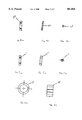
- FIG. 1a shows a typical support spring installed between a cold finger and a resonator.
- FIG. 1b shows a typical cross section of a support spring.
- FIG. 2a shows a typical cross sectional view of a support spring.
- FIG. 2b shows a typical plan view of a support spring viewed from the bottom.
- FIG. 3a shows a typical cross sectional view of a damper strap.
- FIG. 3b shows a typical plan view of a damper strap viewed from the bottom.
- FIG. 4a shows a plan view of a typical outer clamp bar.
- FIG. 4b shows a typical cross sectional view along the center axis of an outer clamp bar.
- FIG. 4c shows a typical cross section through an outer clamp bar.
- FIG. 5a shows a plan view of a typical inner clamp bar.
- FIG. 5b shows a typical cross sectional view along the center axis of a typical inner clamp bar.
- FIG. 5c shows a typical cross sectional view through a typical inner clamp bar.
- FIG. 6a shows a cross sectional view of a typical damper clip.
- FIG. 6b shows a plan view of a typical damper clip.
- FIG. 7 shows a plot of measured acceleration ratios of a support spring as shown in FIG. 1.
- FIG. 8 shows a WGM-5 resonator, support spring, and radiation shield of a cryogenic subsystem.
- the preferred embodiment of this invention is a support spring 12, as shown in FIG. 1, supporting a pair of resonators 14 from a cold finger 16 of an open-cycle cryocooler 10.
- the support spring 12 is damped. Since viscoelastic materials are unsuitable for the low-temperature, high vacuum environment in which the spring must operate, the spring is damped with friction forces.
- Each damper clip 18 pinches the damper strap 22 and the support spring 12 together with a force of about 64 N, and outer and inner clamp bars 24 and 25, respectively, clamp them together at the 90 degree position.
- the support spring 12 as shown in FIGS. 2a and 2b, and the damper strap 22, as shown in FIGS. 3a and 3b, are preferably made from aluminum, such as 6061-T6 aluminum sheet 0.048 inches thick and are hard anodized to prevent galling and wear, a technique well known to those skilled in the art. However, any other type metal desired may be used by those skilled in the art.
- the outer clamp bar 24, as shown in FIGS. 4a, 4b and 4c, the inner clamp bar 25, as shown in FIGS. 5a, 5b and 5c, are, preferably, made of a 303 stainless steel and secured to the support spring 12 and damper strap 22, preferably, by Allen screws.
- the damper clip 18, as shown in FIGS. 6a and 6b, is made, preferably of 2024-T3 or 6061-T61 aluminum tubing. In all instances these are only suggested materials and the aforementioned components may be made of any material the artisan skilled in the art may determine to fit the installation best.
- the vertical vibration isolation, A 2v /A 1v , of the support spring 12, is shown in FIG. 7.
- the vibration transmission peaks at 92 Hz, 1583 Hz, and 2514 Hz are significant, but very much smaller than the peaks that would be obtained if the spring were undamped. Away from the peaks the vibration isolation is 40 dB or more above 1 kHz. Because of its curved construction, the spring also provides reasonably good vibration isolation in the other two directions (L and T) even though it is made wide and thin to provide good thermal conductivity. These values are shown for a typical installation, as shown in FIG. 1, in FIG. 7.
- This support spring 36 is similar to the embodiment shown in FIG. 1 except that the spring 36 radius was increased so that the resonator 32 would nest within the spring 36 for compactness, and the thickness of the spring 36 and damper strap 38 were increased. The new proportions made the fundamental natural frequencies in the vertical, lengthwise, and transverse directions more equal.
- the damper clip 42 force was optimized experimentally to minimize the transmission peaks in the intermediate frequency range of main interest.
- the support spring 36 provides good thermal conductivity and good vibration isolation at most frequencies, but relatively poor vibration isolation at a few resonant frequencies. At those frequencies, the other vibration stages provide most of the isolation. If coincidences had occurred between the support spring 44 transmission peaks and the transmission peaks of the other vibration isolation stages, the support spring 36 resonances could have been changed easily by changing the masses of the present spring clamp bars 46 at the spring 36 mid-span.
Abstract
This invention is a support spring made of a material, such as aluminum, that is damped by friction forces to directly support a sapphire dielectric resonator operating from a cold finger at cryogenic temperatures in a spring-mounted enclosure to reduce a phase-noise vibration sensitivity of the sapphire dielectric resonator. The support spring provides vibration isolation in al three directions, along with good thermal conductivity to aid in resonator cool-down. A damper clamp and damper clips provide the friction forces necessary for damping which prevents large vibration transmission peaks in a hostile, low-temperature, high-vacuum environment.
Description
1. Field of the Invention
This invention pertains generally to a damping support spring for supporting an object and more particularly to a spring arrangement for supporting a cold finger of an open-cycle cryocooler.
2. Description of the Related Art
The development of very low phase noise in cryogenic radars requires the use of sapphire dielectric resonators at X-band frequencies operating at cryogenic temperatures to achieve loaded Q's greater than 3×10⁶. A phase-noise goal of -145 dBc /Hz at 1 KHz offset, which corresponds to an allowable frequency jitter Δf of 3×10⁻⁵ Hz, imposes significant vibration sensitivity requirements on the resonator. A dielectric resonator/oscillator including a sapphire puck that is soft-mounted in a metal enclosure operating in a 5th -order whispering gallery mode wherein the resonator frequency is affected by very small relative axial and radial displacements of the inner surfaces of the enclosure, so that a support spring must provide effective vibration isolation in all three directions to achieve a required low phase-noise goal. The support spring must be damped to avoid excessive vibration transmission at its natural frequencies and it must have high thermal conductivity to conduct heat from the resonator to the cold finger without excessive temperature drop.
Currently resonators are cooled with a liquid nitrogen bath and they are not directly supported from a cold finger with a spring, or supported with a spring from a cold radiation shield which is connected to the cold finger of a closed-cycle cryocooler.
The object of this invention is to provide a support spring to directly support a sapphire dielectric resonator operating from a cold finger at cryogenic temperatures in a spring-mounted enclosure
These and other objectives are accomplished by a support spring made of a material, such as aluminum, that is damped by friction forces to reduce the phase-noise vibration sensitivity of a sapphire dielectric resonator. The support spring provides vibration isolation in all three directions, along with good thermal conductivity to aid in resonator cool-down. A damper clamp and damper clips provide friction damping which prevents large vibration transmission peaks in a hostile, low-temperature, high-vacuum environment.
FIG. 1a shows a typical support spring installed between a cold finger and a resonator.
FIG. 1b shows a typical cross section of a support spring.
FIG. 2a shows a typical cross sectional view of a support spring.
FIG. 2b shows a typical plan view of a support spring viewed from the bottom.
FIG. 3a shows a typical cross sectional view of a damper strap.
FIG. 3b shows a typical plan view of a damper strap viewed from the bottom.
FIG. 4a shows a plan view of a typical outer clamp bar.
FIG. 4b shows a typical cross sectional view along the center axis of an outer clamp bar.
FIG. 4c shows a typical cross section through an outer clamp bar.
FIG. 5a shows a plan view of a typical inner clamp bar.
FIG. 5b shows a typical cross sectional view along the center axis of a typical inner clamp bar.
FIG. 5c shows a typical cross sectional view through a typical inner clamp bar.
FIG. 6a shows a cross sectional view of a typical damper clip.
FIG. 6b shows a plan view of a typical damper clip.
FIG. 7 shows a plot of measured acceleration ratios of a support spring as shown in FIG. 1.
FIG. 8 shows a WGM-5 resonator, support spring, and radiation shield of a cryogenic subsystem.
The preferred embodiment of this invention is a support spring 12, as shown in FIG. 1, supporting a pair of resonators 14 from a cold finger 16 of an open-cycle cryocooler 10. To avoid large vibration transmission peaks in the frequency range of interest, the support spring 12 is damped. Since viscoelastic materials are unsuitable for the low-temperature, high vacuum environment in which the spring must operate, the spring is damped with friction forces. Each damper clip 18 pinches the damper strap 22 and the support spring 12 together with a force of about 64 N, and outer and inner clamp bars 24 and 25, respectively, clamp them together at the 90 degree position. As the support spring 12 is deflected, the damper strap 22 slips slightly on the support spring 12, especially near the ends of the damper strap 22, unless the damper clip 18 forces are too large. The damper clip 18 forces are optimized to maximize the friction damping. The support spring 12, as shown in FIGS. 2a and 2b, and the damper strap 22, as shown in FIGS. 3a and 3b, are preferably made from aluminum, such as 6061-T6 aluminum sheet 0.048 inches thick and are hard anodized to prevent galling and wear, a technique well known to those skilled in the art. However, any other type metal desired may be used by those skilled in the art.
The outer clamp bar 24, as shown in FIGS. 4a, 4b and 4c, the inner clamp bar 25, as shown in FIGS. 5a, 5b and 5c, are, preferably, made of a 303 stainless steel and secured to the support spring 12 and damper strap 22, preferably, by Allen screws. The damper clip 18, as shown in FIGS. 6a and 6b, is made, preferably of 2024-T3 or 6061-T61 aluminum tubing. In all instances these are only suggested materials and the aforementioned components may be made of any material the artisan skilled in the art may determine to fit the installation best.
The vertical vibration isolation, A2v /A1v, of the support spring 12, is shown in FIG. 7. The vibration transmission peaks at 92 Hz, 1583 Hz, and 2514 Hz are significant, but very much smaller than the peaks that would be obtained if the spring were undamped. Away from the peaks the vibration isolation is 40 dB or more above 1 kHz. Because of its curved construction, the spring also provides reasonably good vibration isolation in the other two directions (L and T) even though it is made wide and thin to provide good thermal conductivity. These values are shown for a typical installation, as shown in FIG. 1, in FIG. 7.
A typical spring for use in a WGM-5 resonator 20, as shown in FIG. 8, supports the resonator 32 from a radiation shield 34 of the cryogenic subsystem. This support spring 36 is similar to the embodiment shown in FIG. 1 except that the spring 36 radius was increased so that the resonator 32 would nest within the spring 36 for compactness, and the thickness of the spring 36 and damper strap 38 were increased. The new proportions made the fundamental natural frequencies in the vertical, lengthwise, and transverse directions more equal. The damper clip 42 force was optimized experimentally to minimize the transmission peaks in the intermediate frequency range of main interest. The support spring 36 provides good thermal conductivity and good vibration isolation at most frequencies, but relatively poor vibration isolation at a few resonant frequencies. At those frequencies, the other vibration stages provide most of the isolation. If coincidences had occurred between the support spring 44 transmission peaks and the transmission peaks of the other vibration isolation stages, the support spring 36 resonances could have been changed easily by changing the masses of the present spring clamp bars 46 at the spring 36 mid-span.
Although this invention has been described in relation to an exemplary embodiment thereof, it will be understood by those skilled in the art that still other variations and modifications can be affected in the preferred embodiment without detracting from the scope and spirit of the invention as stated in the claims.
Claims (2)
1. A spring to support sapphire dielectric resonator operating from a cold finger at cryogenic temperatures comprising:
a support spring mounted between the cold finger and resonator;
a damper clamp mounted adjacent to said support spring not touching either the cold finger or the resonator;
a plurality of damper clips affixed around the support spring and said damper clamp pinching the support spring and damper clamp together; and
said damper clips and said damper clamp cooperating so as to provide friction damping thereby preventing large vibration transmission peaks, hence reducing phase-noise vibration between the cold finger and resonator.
2. A method for reducing phase-noise vibration between a cold finger and a sapphire dielectric resonator operating at cryogenic temperatures comprising the steps of:
mounting a support spring between the cold finger and resonator;
mounting a damper clamp adjacent to said support spring not touching either the cold finger or the resonator;
affixing a plurality of damper clips around the support spring and said damper clamp pinching the support spring and damper clamp together; and
said damper clips and said damper clamp cooperating so as to provide friction damping thereby preventing large vibration transmission peaks, hence reducing phase-noise vibration between the cold finger and resonator.
Priority Applications (1)
| Application Number | Priority Date | Filing Date | Title |
|---|---|---|---|
| US09/288,044 USH1866H (en) | 1999-04-06 | 1999-04-06 | Support spring for a cryocooler |
Applications Claiming Priority (1)
| Application Number | Priority Date | Filing Date | Title |
|---|---|---|---|
| US09/288,044 USH1866H (en) | 1999-04-06 | 1999-04-06 | Support spring for a cryocooler |
Publications (1)
| Publication Number | Publication Date |
|---|---|
| USH1866H true USH1866H (en) | 2000-10-03 |
Family
ID=23105507
Family Applications (1)
| Application Number | Title | Priority Date | Filing Date |
|---|---|---|---|
| US09/288,044 Abandoned USH1866H (en) | 1999-04-06 | 1999-04-06 | Support spring for a cryocooler |
Country Status (1)
| Country | Link |
|---|---|
| US (1) | USH1866H (en) |
Cited By (1)
| Publication number | Priority date | Publication date | Assignee | Title |
|---|---|---|---|---|
| US6422025B1 (en) * | 2001-03-21 | 2002-07-23 | The Coca-Cola Company | Vibrationally isolated stirling cooler refrigeration system |
-
1999
- 1999-04-06 US US09/288,044 patent/USH1866H/en not_active Abandoned
Cited By (1)
| Publication number | Priority date | Publication date | Assignee | Title |
|---|---|---|---|---|
| US6422025B1 (en) * | 2001-03-21 | 2002-07-23 | The Coca-Cola Company | Vibrationally isolated stirling cooler refrigeration system |
Similar Documents
| Publication | Publication Date | Title |
|---|---|---|
| US20190025166A1 (en) | Cryostat Sample Support Assemblies and Methods for Supporting a Sample During Cryo Analysis | |
| US7287387B2 (en) | Cooling apparatus | |
| Dick et al. | Cryo-cooled sapphire oscillator with ultra-high stability | |
| US7358736B2 (en) | Low temperature probe for NMR and NMR device | |
| Uchiyama et al. | Present status of large-scale cryogenic gravitational wave telescope | |
| US4736173A (en) | Thermally-compensated microwave resonator utilizing current-null segmentation | |
| CA2615281C (en) | Method and system for cryogenic cooling | |
| USH1866H (en) | Support spring for a cryocooler | |
| JPH1116719A (en) | Mri superconducting magnet assembly | |
| JPH11330815A (en) | Resonator hollow end part wall structure | |
| US10401447B2 (en) | Cooling device, comprising a cryostat and a cold head having improved decoupling to a cooling system | |
| US5628195A (en) | Vibrationally isolated thermal system for a cryogenically cooled device | |
| US3414847A (en) | High q reference cavity resonator employing an internal bimetallic deflective temperature compensating member | |
| US4694175A (en) | Thermal damper for infrared detector | |
| Veprik et al. | Ultra-light weight undamped tuned dynamic absorber for cryogenically cooled infrared electro-optic payload | |
| Raccanelli et al. | Eliminating the vibrational noise in continuously filled 1 K pots | |
| Arts et al. | High-availability cryocooling for infrared sensors | |
| Sugimoto et al. | Thermal link for cartridge-type cryostat | |
| US11692673B1 (en) | Tensioned intra-Dewar spider assembly | |
| Riabzev et al. | RICOR K527 highly reliable linear cooler: applications and model overview | |
| Dick et al. | Cryo-cooled sapphire oscillator for the Cassini Ka-band experiment | |
| KR20190119923A (en) | Cryostat using 1K Sub Cooler for sample mounting on the external side | |
| US11125663B1 (en) | Cryogenic systems and methods | |
| US11287086B1 (en) | Intra-dewar structure | |
| Driscoll | Advances in resonator technology support improved microwave signal spectral performance. |
Legal Events
| Date | Code | Title | Description |
|---|---|---|---|
| STCF | Information on status: patent grant |
Free format text: PATENTED CASE |