US999198A - Tidal-power device. - Google Patents
Tidal-power device. Download PDFInfo
- Publication number
- US999198A US999198A US55246610A US1910552466A US999198A US 999198 A US999198 A US 999198A US 55246610 A US55246610 A US 55246610A US 1910552466 A US1910552466 A US 1910552466A US 999198 A US999198 A US 999198A
- Authority
- US
- United States
- Prior art keywords
- float
- shaft
- tidal
- compartment
- secured
- Prior art date
- Legal status (The legal status is an assumption and is not a legal conclusion. Google has not performed a legal analysis and makes no representation as to the accuracy of the status listed.)
- Expired - Lifetime
Links
- 230000005540 biological transmission Effects 0.000 description 2
- 230000005484 gravity Effects 0.000 description 2
- XLYOFNOQVPJJNP-UHFFFAOYSA-N water Substances O XLYOFNOQVPJJNP-UHFFFAOYSA-N 0.000 description 2
- 238000001363 water suppression through gradient tailored excitation Methods 0.000 description 2
- LTMHDMANZUZIPE-PUGKRICDSA-N digoxin Chemical compound C1[C@H](O)[C@H](O)[C@@H](C)O[C@H]1O[C@@H]1[C@@H](C)O[C@@H](O[C@@H]2[C@H](O[C@@H](O[C@@H]3C[C@@H]4[C@]([C@@H]5[C@H]([C@]6(CC[C@@H]([C@@]6(C)[C@H](O)C5)C=5COC(=O)C=5)O)CC4)(C)CC3)C[C@@H]2O)C)C[C@@H]1O LTMHDMANZUZIPE-PUGKRICDSA-N 0.000 description 1
- 238000000034 method Methods 0.000 description 1
- 230000001105 regulatory effect Effects 0.000 description 1
- 230000000630 rising effect Effects 0.000 description 1
- 239000000725 suspension Substances 0.000 description 1
Images


Classifications
-
- F—MECHANICAL ENGINEERING; LIGHTING; HEATING; WEAPONS; BLASTING
- F03—MACHINES OR ENGINES FOR LIQUIDS; WIND, SPRING, OR WEIGHT MOTORS; PRODUCING MECHANICAL POWER OR A REACTIVE PROPULSIVE THRUST, NOT OTHERWISE PROVIDED FOR
- F03B—MACHINES OR ENGINES FOR LIQUIDS
- F03B17/00—Other machines or engines
-
- Y—GENERAL TAGGING OF NEW TECHNOLOGICAL DEVELOPMENTS; GENERAL TAGGING OF CROSS-SECTIONAL TECHNOLOGIES SPANNING OVER SEVERAL SECTIONS OF THE IPC; TECHNICAL SUBJECTS COVERED BY FORMER USPC CROSS-REFERENCE ART COLLECTIONS [XRACs] AND DIGESTS
- Y02—TECHNOLOGIES OR APPLICATIONS FOR MITIGATION OR ADAPTATION AGAINST CLIMATE CHANGE
- Y02E—REDUCTION OF GREENHOUSE GAS [GHG] EMISSIONS, RELATED TO ENERGY GENERATION, TRANSMISSION OR DISTRIBUTION
- Y02E10/00—Energy generation through renewable energy sources
- Y02E10/20—Hydro energy
Definitions
- T. G. B1111 TIDAL POWER DEVICE.
- My invention relates 1 class of devices for utilizing the power developed by the ebb and flow of ocean tides.
- the object of my invention is to provide a device wherein a float is caused to rise by the tides andthe power derived from its gravity movement is transmitted through suitahle and convenient mechanism for use wherever desired.
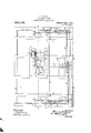
- Figure 1 is a plan view of my device.
- l ig. 2 is a sectional side elevation of the same.
- Fig. 3 is a sectional rear elevation of the device.
- Fig.4 is a sectional view on the line A. ⁇ ofFig. 1. showing detail of the governor mechanism only.
- B is a vessel or compartment placed in a suitable position where tidal water may tlow in and out of it.
- C is a. float within the compartment and movable vertically therein.
- transverse shafts 1-3-l5 are placed im mediately above the worm wheels 8"'.
- worms 16--16 which engage the worm
- These shafts rotate in bearings of a frame placed on the upper part of the compartment B.
- sprockets 171T are rigidly secured.
- a governor shaft 18, rotatable in bearings of a frame on the upper part of the compartment 13. is placed transversely and 11 air the center of the compartment.
- two sprockets 19l9 are rigidly secured to it. From and about these sprockets, link chains 2020' extend about the sprockets 1717 of the shafts 151 respectively.
- ratchet pinion 21 is rigidly secured thereon.
- a ratchet wheel 22 is rotatably mounted on the shaft 18.
- pawls 23 are pivoted in position to engage the ratchet pinion 21.
- Parallel with the shaft 18 and ncarihtwo shorter shafts 21-2-1 are rotatably mounted in bearings in the frames on the upper part of the compartment B. Near the ends of these shafts are rigidly mounted toothedwheels 252525 which form a train of gearing connecting the shafts 1S and 21.
- Near one end of the shaft 21' is a recoil or anchor eseapement mechanism, comprising the toothed wheel 26, rigidly secured on the shaft 21, an anchor QTrigidly secured above the wheel 26 on a pivot 2 and provided with pallets 29-29 placed to engage the teeth of the wheel 26.
- a pendulum 30 is rigidly secured at its upper end to the pivot 2o alongside the anchor.
- a spool 31 is rigidly secured on the shaft 18.
- a cord is secured toand coiled around this spool and a weight is secured to the lower end of the cord.
- Near the ratchet pinion 21 second spool Ellis rigidly secured on the shaft 18.
- a cord 35 is coiled around and secured at one end to the spool 31 and at the opposite end to asuitable. part of the upper frame' A weight 38. suitably lighter than the weight. 33, is suspended on the cord 35 by means of a pulley 37.
- a pulley a is rigidly secured.
- a locking key 38 see Fig. 4 is provided to lock the escapement mechanism when it is desired to shut off the transmission of power.
- the compartment B is provided with a gate B for the purpose of admitting the tide to raise the float and to prevent its inflow while the float is descending and transmitting power.
- This gate may be raised or lowered by screws or any suitable mechanism which it maybe desired or is 'convenient to provide for the purpose but .no claims being made for the manner of moving the gates no particular method is shown.
- the float is shown at the bottom of the compartment, the weights 14:1l and 3333 having descendedalso, while the weight 86 is at its height;
- the gate B is thenfopened and the rising tide allowed to flow into the compartment B.
- This raises the float C which in turn carries upward the weights- 33-33 until these are respectively in the dotted line positions shown at C, and 33 while the weight 36 descends to the dotted line position 36 and the weights-PL-M to the dotted line positionslsl.
- the weights 1414 take up the slack of the chains 1l11 drawing the pawls backward over the ratchet pinions 77' and the light weight 36 causes the governor shaft-18 to rotatebackward,drawing the pawls 23 over theratchet pinion 21.
- the mechanism is prevented from operating by the key 138 inserted in the path of the pendulum, and the float held suspended at its height until the tide is again at .ebb' when the gate B is closed to shut out the water.
- the mechanism then being released by removal of the key 38, the float descends bygravity and by means of the intervening mechanism rotates the shaft D and the power thus created is transmitted by means of the pulley w td any desired place.
- the rotary speed of the shaft D, the gravity action of the float C and the rotation of the pulley m are governet l by the escapement mechanism, througlr its train of gearing to the shaft 18 and from thence by other intervening mcchanisi to an engagement with the worm wheels 8' mounted on' the shaft D.
- the speed is regulated by the adjustment of the pendulum 30 to swing at a desired. movement.
- the weights 14 14 ascend and 33- -.33 descend, while the'iight weight 36 ascends to its mean height.
- my device is arranged so that it may be operated by tides oil any height, and by means of the float weights and their suspension, energy may bestored for use at such times as power is desired.
- a tidal power device comprising a compartment, a float of suitable weight movable vertically'therein suspended from sprocket wheels rotatably mounted on a main shaft, a rotatable main shaft having near its ends ratchet pinions rigidly secured thereon and sprocket wheels rotatable on the shaft, pro vided with pawls on one face in position to engage the pinion ratchets when the float descends, link chains having one end se- ""cured to the float and passing over the sprocket wheels, also meansto cause said chains to rotate the pawl sprockets reversely when the float ascends substantially as department provided with water gates, a float I of suitable weight movable vertically therein suspended from sprocket wheels rotatably mounted on a main shaft, a rotatable main shaftha'ving near its ends-ratchet pinions rigidly secured thereon and sprocket wheels rotatable on the shaft, provided with
- a tidal power device comprising a compartment, a float of suitable weight movable vertically therein suspended from sprocket wheels rotatably mounted on a'inaiu shaft, a rotatable main shaft having near its ends ratchet pinions rigidly secured thereon and sprocket wheels rotatable on the shaft pro the float ascends, worm wheels rotatably -mounted on the main shaft near its ends and means'to lock, release, and govern the speed of their movement, consisting of a suitable escapcrnent mechanism conveniently. placed and other intervening mechanism leading therefrom to engagement with said worm wheels, substantially as described.
Landscapes
- Engineering & Computer Science (AREA)
- Chemical & Material Sciences (AREA)
- Combustion & Propulsion (AREA)
- Mechanical Engineering (AREA)
- General Engineering & Computer Science (AREA)
- Other Liquid Machine Or Engine Such As Wave Power Use (AREA)
Description
T. G. B1111). TIDAL POWER DEVICE.
APPLICATION FILED 111113.30, 1910.
999,198. Patented Aug. 1, 1911.
4 SHEETB-SHBET 1.
ZVIZfSSCS J v T T. G. BIRD.
TIDAL POWER DEVICE.
APPLICATION FILED MAR. 30, 1910.
999,198. Patented Aug. 1,1911.
BET 2. x Q 4 SHEETS SH f aw Patented Aug. 1, 1911.
f/rve/ra/r 4. v
T. G. BIRD. TIDAL POWER DEVICE.
APPLICATION FILED MAR. 30, 1910.
Patented Aug. 1, 1911.
4 SHEETS-SHEET 4.
. wheels St" and sprocket wheels 5) UNITED PATENT ()FFICE.
THOMAS G. BIRD, 0F EUGENE, OREGON; ASSIGNOR OF T'WO-FIFTHS TO MARCELLUS P.
i BONNETT, OF EUGENE, OREGON.
TIDAL-POWER DEVICE.
To all whom it may concern:
Be it known that I, THOMAS G. 131m), a citizen of the United States, residing 'at Eugene, in the county of Lane and State of Oregon, have invented a new and useful Improvement in Tidal-Power 'Devices, of which the following is a specification, reference being had-to the accompanying drawings. l I
My invention relates 1 class of devices for utilizing the power developed by the ebb and flow of ocean tides.
The object of my invention is to provide a device wherein a float is caused to rise by the tides andthe power derived from its gravity movement is transmitted through suitahle and convenient mechanism for use wherever desired. I attain these objects as well as other advantages, by the constriwtion, combination and arrangement of parts illustrated in the accompanying drawings which form a. part hereof.
Figure 1 is a plan view of my device. l ig. 2 is a sectional side elevation of the same. Fig. 3 is a sectional rear elevation of the device. Fig.4 is a sectional view on the line A.\ ofFig. 1. showing detail of the governor mechanism only.
Like numerals and letters refer to like parts throughout the views. L
B is a vessel or compartment placed in a suitable position where tidal water may tlow in and out of it.
C is a. float within the compartment and movable vertically therein.
1) is a main shaft extending. longitudinally of the compartment 13 with bea ings 55' on transverse beams (3-G near the top thereof. On the ends of the shaft 1) ratchet pinions 77' are rigidly secured. \Vorm 9 are united as one member and this member rotatably mounted on the shaft D as a unit. Between these pinions and worm wheels are placed sprocket wheels 9 9, rotatable on the shaft D. Pawls it) are pivoted upon the faces ofv the sprockets 9-9- in position to engage the ratchet pinions 7-7'. Sprocket. chains 1111 are secured by one end to the float C near each end thereof and extended over the sprockets 9-9' a. suitable distance. To the opposite ends of the chains 1111 are secured cords 12-42 which pass under pulleys 1313" which are securedto weights 1414 and extend to the Specification of Letters Patent.
Application filed March 30, 1910.
' wheels SS'.
Patented Aug. 1, 1911. Serial No. 552,466.
wall of thecompartment or frame thereon to which the opposite ends of the cords are secured. At each end of the compartment B, transverse shafts 1-3-l5 are placed im mediately above the worm wheels 8"'. On the central parts of the shafts 15 15 are worms 16--16 which engage the worm These shafts rotate in bearings of a frame placed on the upper part of the compartment B. Near one end of the shafts 15-45, sprockets 171T are rigidly secured. A governor shaft 18, rotatable in bearings of a frame on the upper part of the compartment 13. is placed transversely and 11 air the center of the compartment. Near one end of the shaft 18 two sprockets 19l9 are rigidly secured to it. From and about these sprockets, link chains 2020' extend about the sprockets 1717 of the shafts 151 respectively.
Near the opposite end of the shaft 18a ratchet pinion 21 is rigidly secured thereon.
Beyond this ratchet pinion, a ratchet wheel 22 is rotatably mounted on the shaft 18.
Upon one face of the wheel 22 pawls 23 are pivoted in position to engage the ratchet pinion 21. Parallel with the shaft 18 and ncarihtwo shorter shafts 21-2-1 are rotatably mounted in bearings in the frames on the upper part of the compartment B. Near the ends of these shafts are rigidly mounted toothedwheels 252525 which form a train of gearing connecting the shafts 1S and 21. Near one end of the shaft 21' is a recoil or anchor eseapement mechanism, comprising the toothed wheel 26, rigidly secured on the shaft 21, an anchor QTrigidly secured above the wheel 26 on a pivot 2 and provided with pallets 29-29 placed to engage the teeth of the wheel 26. A pendulum 30 is rigidly secured at its upper end to the pivot 2o alongside the anchor. Near the. sprocket 19, a spool 31 is rigidly secured on the shaft 18. A cord is secured toand coiled around this spool and a weight is secured to the lower end of the cord. Near the ratchet pinion 21 second spool Ellis rigidly secured on the shaft 18. A cord 35 is coiled around and secured at one end to the spool 31 and at the opposite end to asuitable. part of the upper frame' A weight 38. suitably lighter than the weight. 33, is suspended on the cord 35 by means of a pulley 37. Upon one extreme end of the shaft D a pulley a; is rigidly secured. A
belt may be passedover this pulley as a means for transmitting power to any de-. sired place. A locking key 38 see Fig. 4 is provided to lock the escapement mechanism when it is desired to shut off the transmission of power.
The compartment B is provided with a gate B for the purpose of admitting the tide to raise the float and to prevent its inflow while the float is descending and transmitting power. This gate may be raised or lowered by screws or any suitable mechanism which it maybe desired or is 'convenient to provide for the purpose but .no claims being made for the manner of moving the gates no particular method is shown.
It will now be seen that the float is shown at the bottom of the compartment, the weights 14:1l and 3333 having descendedalso, while the weight 86 is at its height; The gate B is thenfopened and the rising tide allowed to flow into the compartment B. This raises the float C which in turn carries upward the weights- 33-33 until these are respectively in the dotted line positions shown at C, and 33 while the weight 36 descends to the dotted line position 36 and the weights-PL-M to the dotted line positionslsl. During this operation the weights 1414 take up the slack of the chains 1l11 drawing the pawls backward over the ratchet pinions 77' and the light weight 36 causes the governor shaft-18 to rotatebackward,drawing the pawls 23 over theratchet pinion 21. When the tide has elevated the float C to its extreme height the mechanism is prevented from operating by the key 138 inserted in the path of the pendulum, and the float held suspended at its height until the tide is again at .ebb' when the gate B is closed to shut out the water. The mechanism then being released by removal of the key 38, the float descends bygravity and by means of the intervening mechanism rotates the shaft D and the power thus created is transmitted by means of the pulley w td any desired place. The rotary speed of the shaft D, the gravity action of the float C and the rotation of the pulley m are governet l by the escapement mechanism, througlr its train of gearing to the shaft 18 and from thence by other intervening mcchanisi to an engagement with the worm wheels 8' mounted on' the shaft D. The speed is regulated by the adjustment of the pendulum 30 to swing at a desired. movement. During the descent of the float the weights 14 14 ascend and 33- -.33 descend, while the'iight weight 36 ascends to its mean height.
It will be seen that my device is arranged so that it may be operated by tides oil any height, and by means of the float weights and their suspension, energy may bestored for use at such times as power is desired. I
contemplate the use of a series of my devices and contend that three of them in operation as I propose will permit the continuous transmission of power. Also the operation of several together with maximum practical float weights will supply a very large amount of power. This power may be first transmitted to dynamos for example, and from them electrical energy transmitted very conveniently to any desirable place.
Having thus described my invention I claim:
1. A tidal power device comprising a compartment, a float of suitable weight movable vertically'therein suspended from sprocket wheels rotatably mounted on a main shaft, a rotatable main shaft having near its ends ratchet pinions rigidly secured thereon and sprocket wheels rotatable on the shaft, pro vided with pawls on one face in position to engage the pinion ratchets when the float descends, link chains having one end se- ""cured to the float and passing over the sprocket wheels, also meansto cause said chains to rotate the pawl sprockets reversely when the float ascends substantially as department provided with water gates, a float I of suitable weight movable vertically therein suspended from sprocket wheels rotatably mounted on a main shaft, a rotatable main shaftha'ving near its ends-ratchet pinions rigidly secured thereon and sprocket wheels rotatable on the shaft, provided with pawls on one race in position to engage the pinion ratchetswhen the float descends, link chains having one end secured to thefloat and passing over the sprocket wheels, also means to cause said chains to rotate the pawl sprockets reversely when the float ascends, substantially as described.
8. A tidal power device comprising a compartment, a float of suitable weight movable vertically therein suspended from sprocket wheels rotatably mounted on a'inaiu shaft, a rotatable main shaft having near its ends ratchet pinions rigidly secured thereon and sprocket wheels rotatable on the shaft pro the float ascends, worm wheels rotatably -mounted on the main shaft near its ends and means'to lock, release, and govern the speed of their movement, consisting of a suitable escapcrnent mechanism conveniently. placed and other intervening mechanism leading therefrom to engagement with said worm wheels, substantially as described.
4. A tidal=power device comprising a com partment provided with water gates, a float of suitable weight movable vertically therein suspended from ,sprocket Wheels rotatably mounted on a main shaft, a rotatable main shaft having near its ends ratchet pinions rigidly secured thereon,'sprocket wheels rotatable on the shaft, provided with pawls on one face in position to engage the pinion ratchets when the float descends, worm I wheels near the pawl sprockets rotatably mounted on the shaft, means to lock, release, and govern the speed of their movement, consisting of a suitable escapement mechanism conveniently placed and other intervening mechanism leading therefrom to engagement with said worm wheels, link chains having one end secured tothe float and passing over the pawl sprockets, means to cause said chains to rotate the pawl sprockets reversely when the float ascends, and a power transmitting pulley on the end of the main shaft, substantially as described.
THOMAS G. BIRD.
lVitnesses C. A. \VILLIAMS, M. L. PRATT.
Priority Applications (1)
| Application Number | Priority Date | Filing Date | Title |
|---|---|---|---|
| US55246610A US999198A (en) | 1910-03-30 | 1910-03-30 | Tidal-power device. |
Applications Claiming Priority (1)
| Application Number | Priority Date | Filing Date | Title |
|---|---|---|---|
| US55246610A US999198A (en) | 1910-03-30 | 1910-03-30 | Tidal-power device. |
Publications (1)
| Publication Number | Publication Date |
|---|---|
| US999198A true US999198A (en) | 1911-08-01 |
Family
ID=3067526
Family Applications (1)
| Application Number | Title | Priority Date | Filing Date |
|---|---|---|---|
| US55246610A Expired - Lifetime US999198A (en) | 1910-03-30 | 1910-03-30 | Tidal-power device. |
Country Status (1)
| Country | Link |
|---|---|
| US (1) | US999198A (en) |
-
1910
- 1910-03-30 US US55246610A patent/US999198A/en not_active Expired - Lifetime
Similar Documents
| Publication | Publication Date | Title |
|---|---|---|
| US3668412A (en) | An apparatus for harnessing the vertical movement of ocean tides and utilize the force for generating electrical energy | |
| US3894241A (en) | Wave action power source | |
| US33156A (en) | Improvement in machinery for ringing fog-bells | |
| US1385083A (en) | Wave-motor | |
| GB336209A (en) | An apparatus for utilizing energy produced by the movements of the sea | |
| US657943A (en) | Tide-motor. | |
| US999198A (en) | Tidal-power device. | |
| US1083794A (en) | Tide-motor. | |
| US1346399A (en) | Wave-energy motor | |
| US968930A (en) | Tide and wave power. | |
| US1256106A (en) | Wave-motor. | |
| US694242A (en) | Wave or tide motor. | |
| DE102017007471A1 (en) | Device for generating energy using the buoyancy force | |
| US1089120A (en) | Tide-power mechanism. | |
| US2384536A (en) | Float operated mechanism | |
| US755799A (en) | Power-transmitting apparatus. | |
| US1170938A (en) | Tide and wave power mechanism. | |
| US347705A (en) | Motor | |
| US1409249A (en) | Hydraulic-power apparatus | |
| US1270221A (en) | Power-generating apparatus. | |
| US811762A (en) | Tide power. | |
| US400500A (en) | Tide and lock power engine | |
| US1498707A (en) | Water motor | |
| US622283A (en) | smith | |
| US1761674A (en) | Wave motor |