US996851A - Circuit-interrupter. - Google Patents
Circuit-interrupter. Download PDFInfo
- Publication number
- US996851A US996851A US58609210A US1910586092A US996851A US 996851 A US996851 A US 996851A US 58609210 A US58609210 A US 58609210A US 1910586092 A US1910586092 A US 1910586092A US 996851 A US996851 A US 996851A
- Authority
- US
- United States
- Prior art keywords
- movable
- stationary
- contact terminals
- operating
- interrupter
- Prior art date
- Legal status (The legal status is an assumption and is not a legal conclusion. Google has not performed a legal analysis and makes no representation as to the accuracy of the status listed.)
- Expired - Lifetime
Links
Images
Classifications
-
- H—ELECTRICITY
- H01—ELECTRIC ELEMENTS
- H01H—ELECTRIC SWITCHES; RELAYS; SELECTORS; EMERGENCY PROTECTIVE DEVICES
- H01H33/00—High-tension or heavy-current switches with arc-extinguishing or arc-preventing means
- H01H33/02—Details
- H01H33/53—Cases; Reservoirs, tanks, piping or valves, for arc-extinguishing fluid; Accessories therefor, e.g. safety arrangements, pressure relief devices
- H01H33/55—Oil reservoirs or tanks; Lowering means therefor
Definitions
- My invention relates to circuit 4interrupters of the oil-i1nmersed type, and it has for its object to provide a device of the above-indicated class which shall be compact and durable in construction and particularly adapted for use in manholes of an underground cable system.
- I provide a water-tight circuit interrupter, of the Inanhole type, which is so constructed that the cable outlets may be independently turned about the axis of the interrupter to any convenient angle, in order to facilitate the work of making connections.
- the interrupter is provided with particularly simple and effective operating mechanism, the operating lever of which may also be turned to any convenient angle and may be locked in either its open or its closed position.
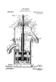
- Figure 1 is a view, partially in vertical section and partially in elevation, of a circuit interrupter constructed in accordance with my invention.
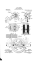
- Fig. 2 is a face view
- Fig. 3 a view in elevat1on, at right angles to that of Fig. 2
- Fig. 4 a plan view of the operating mechanism shown in Fig. 1.
- Fig. 5 is a view, partially ⁇ in section and partially in elevation, of the lower portion of the circuit interrupter shown in Fig. 1, the
- FIG. (3 is a plan view of the circuit interrupter shown in Fig. 1, with the cover removed.
- a circuit interrupter 1 comprises a liquid-containing tank 2 composed of a plurality of relatively movable and substantially cylin- Specication of Letters Patent.
- the lower section 5 of the inclosing tank 2 is provided with a drain outlet 12 and is adapted to be screwed upon section 4, which is provided with a cable out-let projection 13.
- Section 4 is also provided with flanges or webs 14 from which the stationary contact terminals 7 and 8 are rigidly suspended, by means of tie rods 15.
- Section 3 is likewise provided with a suitable cable outlet projection 16 and is adapted to rest upon the upper edge of section 4 and to be secured'thereto by means of an annular member 17 which is screwed upon both of said sections.
- the annular member 17 is provided with a groove 1S to receive a U-shaped member 19 the ends of which are fastened to a supporting wall or member 20, by means of nuts 21, only one of which is shown.
- the cover plate 6 is adapted to be screwed to the upper edgeof section 3 and is provided with ears 25 and 26 to either of which the operating-lever may be secured by means of a lock 2
- all of the threaded joints are filled with a gum (not shown) and the cover (3 is further provided with a stuffing box 2S of the usual type through which a centrally located operating rod 29 projects.
- Suitable packing material 30 is disposed about the shaft or operating rod 29 within the stufing box 28 and a member 31 is provided which is adapted to be forced into position by means of bolts 32.
- rIhe stationary contact terminals 7 and 8 are secured to a circular disk 33 of impregnated wood which is adapted to fit tightly within a cylinder 34 of insulating material which serves as a lining forthe sections 4 and 5.
- the disk 33 is rigidly secured to the flanges 14 of section 4 by means of the tie rods 15, suitable spacing blocks 35 being interposed between the flanges 14 and the disk 33, and similar spacing blocks 36 being provided which extend downwardly from disk 33 and are likewise secured in position by means of the tie rods l5. All of the spacing blocks are of like construction and are segmental in horizontal cross section.
- the spacing blocks 35 are disposed so as to provide an opening ⁇ 37 to accommodate the shaft 29, and a similar opening 38 is provided between the lower spacing blocks 36 to accommodate a supporting member 39 with which the movable contact terminals 9 and 10 are associated.
- rlFhe stationary contact terminal 7 eX- tends through the disk 33 and is screwed into the bottom portion of a terminal block 51 of conducting material, the upper portion of which is secured to a cable 52 by means of screws 53.
- rl ⁇ he stationary contact terminal 8 likewise extends through the disk 33 and is screwed into the outer end of an arm 55 of conductingmaterial, the inner end of which is adapted to be screwthreaded to the lower end of a tube 57 of conducting material which surrounds the operating shaft 29.
- rlhe upper end of the tube 57 is screwed into a terminal block 59, the outer 'end of which is adapted to be connected to a cable 61 by means of screws 62.
- l'llhe tube 57 is insulated from the operating rod 29 by means of a tube 63 of insulating material and from the adjacent flanges 14 by an insulatingl tube 64. Cables 52 and 61 are respectively secured to cable.
- the movable contact terminals 9 and l() are of, like structure and are of the usual butt-contact type. Each of said terminals is adapted to rest upon a coil spring 42 which is disposed within a suitable recess 43 in the supporting member 39.
- a strapconductor 44 is adapted to be connected between contact terminals 9 and 10 and is secured thereto by means of suitable llock nuts 45.
- the supporting member 39 is located between they lower spacing blocks 36, which serve as guides to maintain the stationary and movable contact terminals in alinement.
- the supporting member 39 is'suspended from the operating rod 29 ⁇ and is vsecured thereto by lock'nuts 47.
- a centrally locate-d recess 48 is pavided in the supporting member 39, in
- the operating mechanism 11 comprises a bracket member which is bolted to th'e cover 6 by means of bolts 66, a ⁇ t-runnion member 67 which is secured to the upper end vof the operating rod 29, and an operating lever 68 which is pivotally supported on trunnion extensions 69 and 7 0 of the'member 67.
- the bracket member 65 is provided with two parallel upwardly eitending side members 71 and 7 2, the outer sides of which are provided with cam'recesses' 73 and 74. Slots 75 are likewise provided in the side members 71.and 72 toy serve as guides for ascesi the extensions 69 and 70 of the trunnion member 67.
- the outer end of the operating lever 68 is provided with holes 77 and 78 which are adapted to register with similar holes 77:L and 78a in the ears 25 and 26, respectively, of the cover 6, when the lever 68 is in the one or the other of its extreme positions.
- the inner portion of the operating lever 68 comprisestwo arms 79 and 80, each ot which is provided with a. laterally projecting portion 81. rlhe projecting portions 81 are adapted to extend into the cam recesses 73 and 74 to coperate therewith in the operation of the movable contact members.
- the cable outlet projection 16 may be rotated to any desired angle, as indicated by the dotted lines in Fig. 6, and, in so doing, the terminal block 59 turns about the conducting tube 57 independently of the stationary and movable contact terminals, as will be readily understood.
- the cable outlet projection 13 may similarly be turned to any convenient position, as shown by the dotted lines-in Fig.
- a circuit interrupter comprising a liquid-containing tank composed of a plurality of relatively movable cylindrical sections tted tightly together and provided with cable outlets, coperatingstationary and movable contact members located in said tank, and a centrally located rod adapted to operate said movable members, said coperating J contact members being mounted for rotative movement about said shaft.
- circuit interrupter comprising a plurality of stationary and movable cooperative contact members, and an operating mechanism for said movable members, of a water-tight inclosing tank comprising a plurality. of relatively movable cylindrical sections adapted to be screwed, together, and cable outlet projections associated with separate sections.
- circuit interrupter comprising 'a plurality of stationary and movable coperating contact members, a centrallyl located shaft connected to said movable contactrmembers, and an operating mechanism for said shaft, of an inclosing tank for said parts having suitable cable outlet projections which are adapted to be independently rotated in planes perpendicular to said shaft to any desired positions.
- circuit interrupter comprising a plurality of stationary and movable cooperating contact members, (and an operating mechanism for said movable members, of an axially located means for connecting said operating mechanism to said movable members and about which said Contact members may haverotative movement, an inclosing tank'having relatively rotatable cable outlet projections and a rely atively movable cover upon'v which said operating mechanism is mounted.
- the combination ⁇ with anninclosing tank comprising a plurality of relatively movable cylindrical sections adapted to be Y screwed together, a plurality of stationary contact terminals rigidly secured to, and
Landscapes
- Driving Mechanisms And Operating Circuits Of Arc-Extinguishing High-Tension Switches (AREA)
Description
I'. W. HARRIS. CIRCUIT INTERRUPTER. APPLICATION FILED 001.8, 1910.
996,851. y Patented July 4,1911.
2 SHEETS-SHEET 1.
i ATTORNEY P. W. HARRIS.
GIRCUIT INTERRUPTER.
APPLIOATION FILED 0018, 1910.
Patented July 4, 1911.
2 SHEETS-SHEET 2.
ATTbRNEY n UNITED STATESI PATENT OFFICE.
. PORD W. HARRIS, OF WILKINsDURC, PENNSYLVANIA, AssIGNOR To wRsTINCIIOUsR ELECTRIC AND MANUFACTURING COMPANY, A CORPORATION OF PENNSYLVANIA.
CIRCUIT-INTERRUPTER.
To all whom 'it may concern:
Be it known that I, FORD W. HARRIS, a citizen of the United States, and a resident of lVilkinsburg, in the county of Allegheny and State of Pennsylvania, have invented a new and useful Improvement in Circuit- Interrupters, of which the following is a specification. j
f My invention relates to circuit 4interrupters of the oil-i1nmersed type, and it has for its object to provide a device of the above-indicated class which shall be compact and durable in construction and particularly adapted for use in manholes of an underground cable system.
In underground systems which embody heavy lead covered cables, much difficulty is often encountered in making suitable connections with the various types of apparatus which are usually located within the manholes, on account ofthe limited and crampedl quarters. It is to lessen such difliculties that my invention is particularly adapted.
According to my invention, I provide a water-tight circuit interrupter, of the Inanhole type, which is so constructed that the cable outlets may be independently turned about the axis of the interrupter to any convenient angle, in order to facilitate the work of making connections. Furthermore, the interrupter is provided with particularly simple and effective operating mechanism, the operating lever of which may also be turned to any convenient angle and may be locked in either its open or its closed position.
In the accompanying drawings, Figure 1 `is a view, partially in vertical section and partially in elevation, of a circuit interrupter constructed in accordance with my invention. Fig. 2 is a face view, Fig. 3 a view in elevat1on, at right angles to that of Fig. 2, and Fig. 4 a plan view of the operating mechanism shown in Fig. 1. Fig. 5 is a view, partially `in section and partially in elevation, of the lower portion of the circuit interrupter shown in Fig. 1, the
sectional plane being taken at right angles to that in Fig. 1. Fig. (3 is a plan view of the circuit interrupter shown in Fig. 1, with the cover removed.
Referring to the drawings in detail, a circuit interrupter 1 comprises a liquid-containing tank 2 composed of a plurality of relatively movable and substantially cylin- Specication of Letters Patent.
'Patented July 4, 1911.
Application filed October 8, 1910. Serial No. 586,092.
drical sect-ions 3, 4 and 5 and a cover 6, a plurality of stationary contact terminals 7 and 8J a plurality of movable Contact terminals 9 and 10, adapted to coperate therewith, and an operating mechanism 11 for effecting engagement 'between said statiolr ary and movable contact terminals.
The lower section 5 of the inclosing tank 2 is provided with a drain outlet 12 and is adapted to be screwed upon section 4, which is provided with a cable out-let projection 13. Section 4 is also provided with flanges or webs 14 from which the stationary contact terminals 7 and 8 are rigidly suspended, by means of tie rods 15. Section 3 is likewise provided with a suitable cable outlet projection 16 and is adapted to rest upon the upper edge of section 4 and to be secured'thereto by means of an annular member 17 which is screwed upon both of said sections. The annular member 17 is provided with a groove 1S to receive a U-shaped member 19 the ends of which are fastened to a supporting wall or member 20, by means of nuts 21, only one of which is shown.
The cover plate 6 is adapted to be screwed to the upper edgeof section 3 and is provided with ears 25 and 26 to either of which the operating-lever may be secured by means of a lock 2 In order to provide a water-tight casing, all of the threaded joints are filled with a gum (not shown) and the cover (3 is further provided with a stuffing box 2S of the usual type through which a centrally located operating rod 29 projects. Suitable packing material 30 is disposed about the shaft or operating rod 29 within the stufing box 28 and a member 31 is provided which is adapted to be forced into position by means of bolts 32.
rIhe stationary contact terminals 7 and 8 are secured to a circular disk 33 of impregnated wood which is adapted to fit tightly within a cylinder 34 of insulating material which serves as a lining forthe sections 4 and 5. y The disk 33 is rigidly secured to the flanges 14 of section 4 by means of the tie rods 15, suitable spacing blocks 35 being interposed between the flanges 14 and the disk 33, and similar spacing blocks 36 being provided which extend downwardly from disk 33 and are likewise secured in position by means of the tie rods l5. All of the spacing blocks are of like construction and are segmental in horizontal cross section. The spacing blocks 35 are disposed so as to provide an opening` 37 to accommodate the shaft 29, and a similar opening 38 is provided between the lower spacing blocks 36 to accommodate a supporting member 39 with which the movable contact terminals 9 and 10 are associated.
rlFhe stationary contact terminal 7 eX- tends through the disk 33 and is screwed into the bottom portion of a terminal block 51 of conducting material, the upper portion of which is secured to a cable 52 by means of screws 53. rl`he stationary contact terminal 8 likewise extends through the disk 33 and is screwed into the outer end of an arm 55 of conductingmaterial, the inner end of which is adapted to be screwthreaded to the lower end of a tube 57 of conducting material which surrounds the operating shaft 29. rlhe upper end of the tube 57 is screwed into a terminal block 59, the outer 'end of which is adapted to be connected to a cable 61 by means of screws 62. l'llhe tube 57 is insulated from the operating rod 29 by means of a tube 63 of insulating material and from the adjacent flanges 14 by an insulatingl tube 64. Cables 52 and 61 are respectively secured to cable.
means of outlet projections/13 and 16 by wiped joints 13a and 16a.
' The movable contact terminals 9 and l() are of, like structure and are of the usual butt-contact type. Each of said terminals is adapted to rest upon a coil spring 42 which is disposed within a suitable recess 43 in the supporting member 39. A strapconductor 44 is adapted to be connected between contact terminals 9 and 10 and is secured thereto by means of suitable llock nuts 45.
`The supporting member 39 is located between they lower spacing blocks 36, which serve as guides to maintain the stationary and movable contact terminals in alinement. The supporting member 39 is'suspended from the operating rod 29\and is vsecured thereto by lock'nuts 47. A centrally locate-d recess 48 is pavided in the supporting member 39, in
which is disposed a coil spring 49 which is adapted to disengage the stationary and. movable contact terminals when the operating mechanism is released. l
The operating mechanism 11 comprises a bracket member which is bolted to th'e cover 6 by means of bolts 66, a` t-runnion member 67 which is secured to the upper end vof the operating rod 29, and an operating lever 68 which is pivotally supported on trunnion extensions 69 and 7 0 of the'member 67. The bracket member 65 is provided with two parallel upwardly eitending side members 71 and 7 2, the outer sides of which are provided with cam'recesses' 73 and 74. Slots 75 are likewise provided in the side members 71.and 72 toy serve as guides for ascesi the extensions 69 and 70 of the trunnion member 67.
The outer end of the operating lever 68 is provided with holes 77 and 78 which are adapted to register with similar holes 77:L and 78a in the ears 25 and 26, respectively, of the cover 6, when the lever 68 is in the one or the other of its extreme positions. The inner portion of the operating lever 68 comprisestwo arms 79 and 80, each ot which is provided with a. laterally projecting portion 81. rlhe projecting portions 81 are adapted to extend into the cam recesses 73 and 74 to coperate therewith in the operation of the movable contact members. rlhe shape of the cam recesses 73 and 74, and the form and proportions of the laterally projecting portions 81, are so chosen as to eiiect a vertical movement orp the operating rod as the lever 68 is moved to either of its eXtreme positions.
Assuming the operating lever to be in the posit-ion shown in Fig. 2, the operating shaft 29 is in its lowest position and the movable contact terminals 9 and 10 are out of engagement with the stationary terminals 7 and 8. ln this position the breaker is open. To close the breaker, the lever member 68 is moved to its other extreme position. The operating rod 29 is thereby drawn into its uppermost position by reason of the peculiar shape and relations of the cam recesses 73 and 74, and the projecting portions 81.
lt'is evident from .the construction of the inelosing tank, that the cable outlet projection 16 may be rotated to any desired angle, as indicated by the dotted lines in Fig. 6, and, in so doing, the terminal block 59 turns about the conducting tube 57 independently of the stationary and movable contact terminals, as will be readily understood. The cable outlet projection 13 may similarly be turned to any convenient position, as shown by the dotted lines-in Fig. 6, but, as the stationary contact terminals 7 and 8 are rigidly secured to tank section 4, all of the breaker parts are turned with it, whilethe conducting arm 55 merely rotates about the conducting tube 57 It also is evident that the operating lever 68, and, consequently, the cover 6, may be made to occupy any desired position, independent of the rest of the mechamsm.
While I have shown and described a cir- 1. A circuit interrupter comprising a liquid-containing tank composed of a plurality of relatively movable cylindrical sections tted tightly together and provided with cable outlets, coperatingstationary and movable contact members located in said tank, and a centrally located rod adapted to operate said movable members, said coperating J contact members being mounted for rotative movement about said shaft.
2., The combination with a circuit interrupter comprising a plurality of stationary and movable cooperative contact members, and an operating mechanism for said movable members, of a water-tight inclosing tank comprising a plurality. of relatively movable cylindrical sections adapted to be screwed, together, and cable outlet projections associated with separate sections.
3. The combination with a circuit interrupter comprising 'a plurality of stationary and movable coperating contact members, a centrallyl located shaft connected to said movable contactrmembers, and an operating mechanism for said shaft, of an inclosing tank for said parts having suitable cable outlet projections which are adapted to be independently rotated in planes perpendicular to said shaft to any desired positions.
4. The combination with a circuit interrupter comprising a plurality of stationary and movable cooperating contact members, (and an operating mechanism for said movable members, of an axially located means for connecting said operating mechanism to said movable members and about which said Contact members may haverotative movement, an inclosing tank'having relatively rotatable cable outlet projections and a rely atively movable cover upon'v which said operating mechanism is mounted.
5. The combination `with anninclosing tank comprising a plurality of relatively movable cylindrical sections adapted to be Y screwed together, a plurality of stationary contact terminals rigidly secured to, and
suitably insulated from, one of said cylindrical sections, a plurality of movable contactterminals to cooperate with said stationary contact terminals and an operating mechanism therefor, of means'for maintaining the cooperating contact terminals in alinement.
6. The combination with stationary and movable contact members adapted to coperate with each other, a rod rotatably associated with said movable contact members, and a water-tight tank, the cover of which is adapted for rotative movement independentlyof said tank, of an operating mechanism mounted upon said cover and comprising a lever pivotally supported upon the upper end of said rod and adapted to be moved through substantially 180o and to be locked in either of itslextreme positions, and means coperating with said lever to actuate 4the movable contact members. Y
7. The combination with a liquid-containing tank, stationary and movable coperat-` ing contact terminals and a centrally located operating rod to which said movable contact- FORD W. HARRIS.
Witnesses:
WILSON L. WRIGHT, B. B. HINEs.
Priority Applications (1)
| Application Number | Priority Date | Filing Date | Title |
|---|---|---|---|
| US58609210A US996851A (en) | 1910-10-08 | 1910-10-08 | Circuit-interrupter. |
Applications Claiming Priority (1)
| Application Number | Priority Date | Filing Date | Title |
|---|---|---|---|
| US58609210A US996851A (en) | 1910-10-08 | 1910-10-08 | Circuit-interrupter. |
Publications (1)
| Publication Number | Publication Date |
|---|---|
| US996851A true US996851A (en) | 1911-07-04 |
Family
ID=3065182
Family Applications (1)
| Application Number | Title | Priority Date | Filing Date |
|---|---|---|---|
| US58609210A Expired - Lifetime US996851A (en) | 1910-10-08 | 1910-10-08 | Circuit-interrupter. |
Country Status (1)
| Country | Link |
|---|---|
| US (1) | US996851A (en) |
-
1910
- 1910-10-08 US US58609210A patent/US996851A/en not_active Expired - Lifetime
Similar Documents
| Publication | Publication Date | Title |
|---|---|---|
| US3571543A (en) | Multiple position vacuum interrupter switching device | |
| JP5238632B2 (en) | Gas circuit breaker and gas insulated switchgear | |
| US996851A (en) | Circuit-interrupter. | |
| US2363360A (en) | Circuit interrupter | |
| US3356811A (en) | Oil-type circuit breakers having outer continuous insulating support tube and inner stacked insulating plates providing lateral vent openings | |
| CN102959668B (en) | Compact ground isolator | |
| US3562454A (en) | Positive switch contact operating mechanism for underground switch | |
| US3076081A (en) | Condition-responsive indicating means for an electric circuit breaker | |
| US2261711A (en) | Circuit breaker | |
| US1255176A (en) | Wall-receptacle for vacuum cleaning apparatus. | |
| US2334810A (en) | Power distribution system | |
| US2276006A (en) | Electric switch | |
| US461239A (en) | Horatio a | |
| US2046979A (en) | Transformer switching arrangement | |
| US2317667A (en) | Junction box | |
| US2118427A (en) | Brake switch device | |
| US20250273934A1 (en) | Carbon dioxide gas insulated switchgear | |
| US1164001A (en) | Electric-circuit controller. | |
| US2945110A (en) | Pole unit mechanism | |
| US1123870A (en) | Switch. | |
| US1123283A (en) | System of electric distribution and circuit control. | |
| US1253659A (en) | Switching apparatus. | |
| US1003044A (en) | Circuit-interrupter. | |
| US625232A (en) | wurts | |
| US1694398A (en) | Switchboard mounting of circuit-breaker units |