US9966208B2 - Manual operation device for low voltage switching apparatus - Google Patents
Manual operation device for low voltage switching apparatus Download PDFInfo
- Publication number
- US9966208B2 US9966208B2 US14/901,573 US201414901573A US9966208B2 US 9966208 B2 US9966208 B2 US 9966208B2 US 201414901573 A US201414901573 A US 201414901573A US 9966208 B2 US9966208 B2 US 9966208B2
- Authority
- US
- United States
- Prior art keywords
- ratchet wheel
- pawl
- operating handle
- fixing
- low voltage
- Prior art date
- Legal status (The legal status is an assumption and is not a legal conclusion. Google has not performed a legal analysis and makes no representation as to the accuracy of the status listed.)
- Active
Links
Images


Classifications
-
- H—ELECTRICITY
- H01—ELECTRIC ELEMENTS
- H01H—ELECTRIC SWITCHES; RELAYS; SELECTORS; EMERGENCY PROTECTIVE DEVICES
- H01H21/00—Switches operated by an operating part in the form of a pivotable member acted upon directly by a solid body, e.g. by a hand
- H01H21/02—Details
- H01H21/18—Movable parts; Contacts mounted thereon
- H01H21/22—Operating parts, e.g. handle
- H01H21/24—Operating parts, e.g. handle biased to return to normal position upon removal of operating force
-
- H—ELECTRICITY
- H01—ELECTRIC ELEMENTS
- H01H—ELECTRIC SWITCHES; RELAYS; SELECTORS; EMERGENCY PROTECTIVE DEVICES
- H01H3/00—Mechanisms for operating contacts
- H01H3/02—Operating parts, i.e. for operating driving mechanism by a mechanical force external to the switch
- H01H3/04—Levers
-
- H—ELECTRICITY
- H01—ELECTRIC ELEMENTS
- H01H—ELECTRIC SWITCHES; RELAYS; SELECTORS; EMERGENCY PROTECTIVE DEVICES
- H01H3/00—Mechanisms for operating contacts
- H01H3/22—Power arrangements internal to the switch for operating the driving mechanism
- H01H3/30—Power arrangements internal to the switch for operating the driving mechanism using spring motor
- H01H3/3005—Charging means
- H01H3/3021—Charging means using unidirectional coupling
-
- H—ELECTRICITY
- H01—ELECTRIC ELEMENTS
- H01H—ELECTRIC SWITCHES; RELAYS; SELECTORS; EMERGENCY PROTECTIVE DEVICES
- H01H3/00—Mechanisms for operating contacts
- H01H3/32—Driving mechanisms, i.e. for transmitting driving force to the contacts
- H01H3/34—Driving mechanisms, i.e. for transmitting driving force to the contacts using ratchet
-
- H—ELECTRICITY
- H01—ELECTRIC ELEMENTS
- H01H—ELECTRIC SWITCHES; RELAYS; SELECTORS; EMERGENCY PROTECTIVE DEVICES
- H01H71/00—Details of the protective switches or relays covered by groups H01H73/00 - H01H83/00
- H01H71/10—Operating or release mechanisms
- H01H71/50—Manual reset mechanisms which may be also used for manual release
- H01H71/52—Manual reset mechanisms which may be also used for manual release actuated by lever
Definitions
- the present invention relates to the field of large capacity low voltage switching apparatus, more particularly, relates to a manual operation device for large capacity low voltage switching apparatus.
- the present invention discloses a manual operation device with a small operating force.
- a manual operation device for low voltage switching apparatus is provided.
- An operating handle is provided with a fixing groove.
- the fixing groove is matched with a second fixing plate, the second fixing plate is placed in the fixing groove.
- a reset torsion spring is arranged between the second fixing plate and the fixing groove.
- a pawl is rotatably mounted on the second fixing plate through a fixing pin, the pawl rotates about the fixing pin.
- One end of a first reset spring is connected to the top end of the pawl, the other end of the first reset spring is connected to the operating handle.
- the operating handle is mounted on a mounting shaft of an operating mechanism of the low voltage switching apparatus.
- a mounting plate is provided with a rotation shaft, the rotation shaft is the rotation shaft of an energy storage mechanism of the low voltage switching apparatus.
- the mounting shaft and the rotation shaft are not concentric.
- a ratchet wheel is rotatably mounted on the rotation shaft, the bottom end of the pawl is engaged with an intertooth position of the ratchet wheel.
- a stop detent is provided on the bottom of the mounting plate, the stop detent is rotatably mounted on the mounting plate. The top end of the stop detent is engaged with an intertooth position of the ratchet wheel.
- One end of a second reset spring is connected to the bottom end of the stop detent, the other end of the second reset spring is fixed on the mounting plate.
- the operating handle and the second fixing plate are provided with holes on corresponding positions, the mounting shaft passes through the holes on the operating handle and second fixing plate.
- the operating handle rotates about the mounting shaft, and the reset torsion spring is set on the mounting shaft.
- the mounting plate is provided with a fixing component, the fixing component defines the limit position of the operation handle.
- the operating handle rotates and drives the pawl to move, the bottom end of the pawl, which is engaged with the intertooth position of the ratchet wheel drives the ratchet wheel to rotate about the rotation shaft.
- the ratchet wheel rotates by one tooth and the bottom end of the pawl slides outward along an edge of the tooth of the ratchet wheel.
- the first reset spring pulls the pawl to rotate about the fixing pin, and the bottom end of the pawl enters into a next intertooth position of the ratchet wheel.
- the ratchet wheel rotates to push the stop detent to rotate and make the top end of the stop detent exit from the intertooth position of the ratchet wheel.
- the ratchet wheel rotates by one tooth, the stop detent is pulled by the second reset spring and the top end of the stop detent enters into a next intertooth position of the ratchet wheel.
- the rotation centers of an operating handle and a shaft of the energy storage mechanism are not concentric.
- the operating handle rotates about a different shaft. Rotate the operating handle to drive a pawl mounted on the shaft, the driving torque is enlarged, so that the required manual operating force is significantly reduced.
- FIG. 1 illustrates the installation structure of a manual operation device for a low voltage switch apparatus according to one embodiment of the present invention.
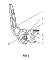
- FIG. 2 illustrates the structure of the operating handle within the manual operation device for a low voltage switch apparatus according to one embodiment of the present invention.
- FIG. 1 illustrates the installation structure of a manual operation device for a low voltage switch apparatus according to one embodiment of the present invention.
- FIG. 2 illustrates the structure of the operating handle therein.
- an operating handle 1 is provided with a fixing groove 13 , the shape and size of the fixing groove 13 is matched with a second fixing plate 6 .
- the second fixing plate 6 is placed in the fixing groove 13 , and a reset torsion spring 2 is arranged between the second fixing plate 6 and the fixing groove 13 .
- the operating handle 1 is mounted on a mounting shaft of an operating mechanism of the low voltage switching apparatus. Refer to FIG.
- the operating handle 1 and the second fixing plate 6 are provided with holes on corresponding positions, the mounting shaft passes through the holes on the operating handle 1 and second fixing plate 6 .
- the operating handle 1 rotates about the mounting shaft, and the reset torsion spring 2 is set on the mounting shaft.
- a pawl 5 is rotatably mounted on the second fixing plate 6 through a fixing pin 4 .
- the pawl 5 rotates about the fixing pin 4 , one end of a first reset spring 3 is connected to the top end of the pawl 5 , the other end of the first reset spring 3 is connected to the operating handle 1 .
- a mounting plate 8 is provided with a rotation shaft 11 and the rotation shaft 11 is the rotation shaft of an energy storage mechanism of the low voltage switching apparatus.
- the mounting shaft 6 is a different shaft with the rotation shaft 11 , the mounting shaft 6 and the rotation shaft 11 are not concentric.
- a ratchet wheel 7 is rotatably mounted on the rotation shaft 11 , the bottom end of the pawl 5 is engaged with an intertooth position of the ratchet wheel 7 .
- the mounting plate 8 is provided with a stop detent 9 on the bottom, the stop detent is rotatably mounted on the mounting plate 8 .
- the rotation shaft of the stop detent 9 is positioned close to the bottom of the stop detent.
- the top end of the stop detent 9 is engaged with an intertooth position of the ratchet wheel 7 .
- the pawl 5 is positioned above the ratchet wheel 7 and the bottom end of the pawl 5 is engaged with the upper intertooth positions of the ratchet wheel 7 .
- the stop detent 9 is positioned beneath the ratchet wheel 7 and the top end of the stop detent 9 is engaged with the lower intertooth positions of the ratchet wheel 7 .
- One end of a second reset spring 10 is connected to the bottom end of the stop detent, the other end of the second reset spring 10 is fixed on the mounting plate 8 .
- the mounting plate 8 is provided with a fixing component 12 which defines the limit position of the operation handle 1 , therefor the operation handle 1 will not be blocked.
- the operating handle 1 rotates and drives the pawl 5 to move.
- the bottom end of the pawl 5 which is engaged with the intertooth position of the ratchet wheel 7 drives the ratchet wheel 7 to rotate about the rotation shaft 11 .
- the ratchet wheel 7 rotates by one tooth and the bottom end of the pawl 5 slides outward along an edge of the tooth of the ratchet wheel 7 , which means the end bottom of the pawl 5 exits from the intertooth position.
- the first reset spring 3 pulls the pawl 5 to rotate about the fixing pin 4 , and the bottom end of the pawl 5 enters into a next intertooth position of the ratchet wheel 7 .
- the ratchet wheel 7 rotates to push the stop detent 9 to rotate and make the top end of the stop detent 9 exit from the intertooth position of the ratchet wheel 7 .
- the ratchet wheel 7 rotates by one tooth, the stop detent 9 is pulled by the second reset spring 10 and the top end of the stop detent 9 enters into a next intertooth position of the ratchet wheel 7 .
- the pawl 5 drives the ratchet wheel 7 to rotate and the stop detent 9 stops and locks the ratchet wheel 7 .
- the ratchet wheel 7 rotates to store energy into the energy storage mechanism. More specifically, as shown in FIG. 1 and FIG.
- the pawl 5 rotates follow the operating handle 1 .
- the tangency of the arc surfaces pulls the ratchet wheel 7 to rotate and performs energy storage operation by driving the rotation shaft 11 which is used for energy storage to rotate.
- the ratchet wheel 7 is driven by the pawl 5 to rotate anti-clockwise, the ratchet wheel 7 pulls the stop detent 9 to rotate clockwise.
- the stop detent 9 is engaged with the ratchet wheel 7 again in a next intertooth position. Stop rotating the operating handle 1 , the operating handle 1 resets under the function of the reset torsion spring 2 and prepares for the next energy storage operation.
- the operating handle 1 is mounted on a shaft which is not concentric with the ratchet wheel 7 .
- the operation handle 1 is rotated anti-clockwise when operated, the pawl 5 rotates and drives the ratchet 7 to perform energy storage operation.
- the torque radius of the driving force is large, a large driving torque is generated and labor-saving effect is achieved.
- the stop detent 9 will enter and lock the ratchet wheel 7 each time the ratchet wheel 7 rotates one tooth, so as to ensure reliable positioning and prepare for the next operation.
- the rotation centers of an operating handle and a shaft of the energy storage mechanism are not concentric.
- the operating handle rotates about a different shaft. Rotate the operating handle to drive a pawl mounted on the shaft, the driving torque is enlarged, so that the required manual operating force is significantly reduced.
Landscapes
- Driving Mechanisms And Operating Circuits Of Arc-Extinguishing High-Tension Switches (AREA)
- Mechanisms For Operating Contacts (AREA)
Abstract
Description
Claims (7)
Applications Claiming Priority (4)
| Application Number | Priority Date | Filing Date | Title |
|---|---|---|---|
| CN201310269945 | 2013-06-28 | ||
| CN201310269945.9A CN104252976B (en) | 2013-06-28 | 2013-06-28 | The hand-operating device of low-tension switch electric appliance |
| CN201310269945.9 | 2013-06-28 | ||
| PCT/CN2014/080920 WO2014206330A1 (en) | 2013-06-28 | 2014-06-27 | Manually operated device of low-voltage power switch |
Publications (2)
| Publication Number | Publication Date |
|---|---|
| US20160372280A1 US20160372280A1 (en) | 2016-12-22 |
| US9966208B2 true US9966208B2 (en) | 2018-05-08 |
Family
ID=52141098
Family Applications (1)
| Application Number | Title | Priority Date | Filing Date |
|---|---|---|---|
| US14/901,573 Active US9966208B2 (en) | 2013-06-28 | 2014-06-27 | Manual operation device for low voltage switching apparatus |
Country Status (5)
| Country | Link |
|---|---|
| US (1) | US9966208B2 (en) |
| EP (1) | EP3016127A4 (en) |
| CN (1) | CN104252976B (en) |
| CA (1) | CA2916114C (en) |
| WO (1) | WO2014206330A1 (en) |
Families Citing this family (11)
| Publication number | Priority date | Publication date | Assignee | Title |
|---|---|---|---|---|
| CN106449307B (en) * | 2015-08-04 | 2019-01-04 | 浙江正泰电器股份有限公司 | Circuit breaker interlocking device |
| WO2017020820A1 (en) * | 2015-08-04 | 2017-02-09 | 浙江正泰电器股份有限公司 | Energy storage operating mechanism for circuit breaker |
| CN106449324B (en) * | 2015-08-04 | 2018-10-19 | 浙江正泰电器股份有限公司 | Circuit breaker handle component |
| CN106783259B (en) * | 2016-12-30 | 2018-08-07 | 施耐德万高(天津)电气设备有限公司 | The energy-stored spring operating mechanism of low voltage isolation switch |
| CN109509653B (en) * | 2017-09-15 | 2022-07-19 | Abb瑞士股份有限公司 | Switching device and associated switch |
| FR3083366B1 (en) | 2018-06-29 | 2020-06-12 | Socomec | MANUAL CONTROL DEVICE FOR A REMOTE HANDLING SOURCE INVERTER |
| CN110947110A (en) * | 2019-12-20 | 2020-04-03 | 河南科技大学 | Automatic inflation device |
| CN110993430A (en) * | 2019-12-30 | 2020-04-10 | 库柏爱迪生(平顶山)电子科技有限公司 | Manual closing mechanism for permanent magnet mechanism |
| US12400807B2 (en) * | 2022-02-18 | 2025-08-26 | Eaton Intelligent Power Limited | Switching assembly with mechanical advantage device |
| CN114530356B (en) * | 2022-03-29 | 2025-08-01 | 浙江人民电器有限公司 | Universal breaker handle structure |
| CN118156099B (en) * | 2024-05-09 | 2024-07-23 | 北陆电气有限公司 | Quick-mounting operating mechanism of universal circuit breaker, circuit breaker and assembly method |
Citations (13)
| Publication number | Priority date | Publication date | Assignee | Title |
|---|---|---|---|---|
| US3234804A (en) | 1963-06-24 | 1966-02-15 | Ite Circuit Breaker Ltd | Spring operator motor charging means |
| CN87216307U (en) | 1987-12-19 | 1988-08-17 | 天津市电气控制设备厂 | Energy-stored manual switching mechanism of vacuum breaker |
| US5889250A (en) | 1997-06-19 | 1999-03-30 | General Electric Company | Circuit breaker closing springs button interlock mechanism |
| CN2341266Y (en) | 1998-01-20 | 1999-09-29 | 余姚市高压电器开关厂 | Hand operated energy storing structure of spring operating mechaism |
| US6072136A (en) * | 1998-05-07 | 2000-06-06 | Eaton Corporation | Electrical switching apparatus with modular operating mechanism for mounting and controlling large compression close spring |
| US6160234A (en) | 1999-04-29 | 2000-12-12 | Eaton Corporation | Reduced drag ratchet |
| CN201051477Y (en) | 2007-06-29 | 2008-04-23 | 常熟开关制造有限公司(原常熟开关厂) | Manual operation machine for breaker |
| CN201112304Y (en) | 2007-09-17 | 2008-09-10 | 德力西电气有限公司 | Hand-operating device of operating mechanism for circuit breaker |
| CN101777440A (en) | 2009-12-24 | 2010-07-14 | 黄勤飞 | Driving device for actuating mechanism |
| CN201898048U (en) | 2010-06-07 | 2011-07-13 | 福建东方电器有限公司 | Novel load switch energy storage mechanism |
| US20120061219A1 (en) | 2010-09-14 | 2012-03-15 | Edward Anthony Prince | Charging Handle Apparatus and Switchgear Apparatus |
| CN102683128A (en) | 2012-04-27 | 2012-09-19 | 贵州长征开关制造有限公司 | Labor-saving operation device of universal breaker operation mechanism |
| CN202855622U (en) | 2012-09-29 | 2013-04-03 | 刘华钱 | Spring operating mechanism |
-
2013
- 2013-06-28 CN CN201310269945.9A patent/CN104252976B/en active Active
-
2014
- 2014-06-27 CA CA2916114A patent/CA2916114C/en active Active
- 2014-06-27 EP EP14818806.3A patent/EP3016127A4/en active Pending
- 2014-06-27 US US14/901,573 patent/US9966208B2/en active Active
- 2014-06-27 WO PCT/CN2014/080920 patent/WO2014206330A1/en not_active Ceased
Patent Citations (14)
| Publication number | Priority date | Publication date | Assignee | Title |
|---|---|---|---|---|
| US3234804A (en) | 1963-06-24 | 1966-02-15 | Ite Circuit Breaker Ltd | Spring operator motor charging means |
| CN87216307U (en) | 1987-12-19 | 1988-08-17 | 天津市电气控制设备厂 | Energy-stored manual switching mechanism of vacuum breaker |
| US5889250A (en) | 1997-06-19 | 1999-03-30 | General Electric Company | Circuit breaker closing springs button interlock mechanism |
| CN2341266Y (en) | 1998-01-20 | 1999-09-29 | 余姚市高压电器开关厂 | Hand operated energy storing structure of spring operating mechaism |
| US6072136A (en) * | 1998-05-07 | 2000-06-06 | Eaton Corporation | Electrical switching apparatus with modular operating mechanism for mounting and controlling large compression close spring |
| US6160234A (en) | 1999-04-29 | 2000-12-12 | Eaton Corporation | Reduced drag ratchet |
| CN201051477Y (en) | 2007-06-29 | 2008-04-23 | 常熟开关制造有限公司(原常熟开关厂) | Manual operation machine for breaker |
| CN201112304Y (en) | 2007-09-17 | 2008-09-10 | 德力西电气有限公司 | Hand-operating device of operating mechanism for circuit breaker |
| CN101777440A (en) | 2009-12-24 | 2010-07-14 | 黄勤飞 | Driving device for actuating mechanism |
| CN201898048U (en) | 2010-06-07 | 2011-07-13 | 福建东方电器有限公司 | Novel load switch energy storage mechanism |
| US20120061219A1 (en) | 2010-09-14 | 2012-03-15 | Edward Anthony Prince | Charging Handle Apparatus and Switchgear Apparatus |
| US8592706B2 (en) * | 2010-09-14 | 2013-11-26 | Eaton Corporation | Charging handle apparatus and switchgear apparatus |
| CN102683128A (en) | 2012-04-27 | 2012-09-19 | 贵州长征开关制造有限公司 | Labor-saving operation device of universal breaker operation mechanism |
| CN202855622U (en) | 2012-09-29 | 2013-04-03 | 刘华钱 | Spring operating mechanism |
Non-Patent Citations (4)
| Title |
|---|
| Chinese Office Action in corresponding Application No. 201310269945.9 dated Nov. 4, 2015 (8 pages). |
| Extended European Search Report issued in corresponding European Application No. 14818806.3 dated Jan. 17, 2017 (9 pages). |
| International Search Report issued in PCT/CN2014/080920 dated Sep. 26, 2014 (2 pages). |
| Written Opinion of the International Searching Authority issued in PCT/CN2014/080920 dated Sep. 26, 2014 (3 pages). |
Also Published As
| Publication number | Publication date |
|---|---|
| US20160372280A1 (en) | 2016-12-22 |
| EP3016127A4 (en) | 2017-02-15 |
| CN104252976B (en) | 2016-12-28 |
| WO2014206330A1 (en) | 2014-12-31 |
| CN104252976A (en) | 2014-12-31 |
| EP3016127A1 (en) | 2016-05-04 |
| CA2916114C (en) | 2021-04-27 |
| CA2916114A1 (en) | 2014-12-31 |
Similar Documents
| Publication | Publication Date | Title |
|---|---|---|
| US9966208B2 (en) | Manual operation device for low voltage switching apparatus | |
| BRPI0913186B1 (en) | MANUAL MANAGEMENT FOR GRADUAL TRANSFER | |
| CN204966424U (en) | Electrically -operated device and miniature circuit breaker | |
| JP2016524348A (en) | Load tap changer and method for adjusting the emergency operation of a defined switching position of a load tap changer | |
| CN104040660A (en) | Power circuit breaker with battery and improved indication of operating status | |
| US3236967A (en) | Switchgear having manual and motor operated spring charging means | |
| CN205376431U (en) | Power -driven operation device | |
| CN104601048A (en) | Operating mechanism of motor starter capable of performing quick breaking | |
| CN105244217A (en) | Operating mechanism of three-station isolating switch | |
| CN106935447A (en) | An electric operating device | |
| EP3531436B1 (en) | Universal circuit breaker energy storage handle anti-jamming apparatus | |
| CN203351457U (en) | Interlocking mechanism among isolating switch, vacuum circuit breaker and cabinet door | |
| CN107230600A (en) | Miniature circuit breaker electrically operated device | |
| CN219696377U (en) | External circuit breaker spring operating mechanism of motor | |
| KR101283648B1 (en) | Gas insulated 3 position switch mechanism | |
| CN206558456U (en) | A kind of manual automatic divide-shut brake switching mechanism of RCCB | |
| CA2934372C (en) | Electric circuit breaker | |
| CN205723395U (en) | Miniature circuit breaker electrically operated device | |
| CN203644702U (en) | Dual-purpose breaker opening and closing apparatus for electric leakage breaker | |
| CN103346482A (en) | Switch cabinet | |
| CN204441136U (en) | The mutual interlocking gear of switchgear and corresponding medium voltage switchgear equipment | |
| CN203026385U (en) | Earthing switch operating mechanism | |
| CN205376432U (en) | Electrically -operated apparatus 's actuating mechanism | |
| CN207282361U (en) | A kind of linkage mechanism, operating mechanism and switchgear | |
| US10593500B2 (en) | Linkage gear mechanism for automatic opening/closing driving mechanism |
Legal Events
| Date | Code | Title | Description |
|---|---|---|---|
| AS | Assignment |
Owner name: SEARI ELECTRIC TECHNOLOGY CO., LTD., CHINA Free format text: ASSIGNMENT OF ASSIGNORS INTEREST;ASSIGNORS:ZHOU, MI;SHEN, DI;YOU, ANSHUN;AND OTHERS;REEL/FRAME:041329/0622 Effective date: 20170208 Owner name: ZHEJIANG CHINT ELECTRICS CO., LTD., CHINA Free format text: ASSIGNMENT OF ASSIGNORS INTEREST;ASSIGNORS:ZHOU, MI;SHEN, DI;YOU, ANSHUN;AND OTHERS;REEL/FRAME:041329/0622 Effective date: 20170208 |
|
| STCF | Information on status: patent grant |
Free format text: PATENTED CASE |
|
| MAFP | Maintenance fee payment |
Free format text: PAYMENT OF MAINTENANCE FEE, 4TH YEAR, LARGE ENTITY (ORIGINAL EVENT CODE: M1551); ENTITY STATUS OF PATENT OWNER: LARGE ENTITY Year of fee payment: 4 |
|
| MAFP | Maintenance fee payment |
Free format text: PAYMENT OF MAINTENANCE FEE, 8TH YEAR, LARGE ENTITY (ORIGINAL EVENT CODE: M1552); ENTITY STATUS OF PATENT OWNER: LARGE ENTITY Year of fee payment: 8 |