US9962303B1 - Combination wheelchair-walker device - Google Patents
Combination wheelchair-walker device Download PDFInfo
- Publication number
- US9962303B1 US9962303B1 US15/657,179 US201715657179A US9962303B1 US 9962303 B1 US9962303 B1 US 9962303B1 US 201715657179 A US201715657179 A US 201715657179A US 9962303 B1 US9962303 B1 US 9962303B1
- Authority
- US
- United States
- Prior art keywords
- frame
- members
- vertical
- wheelchair
- attached
- Prior art date
- Legal status (The legal status is an assumption and is not a legal conclusion. Google has not performed a legal analysis and makes no representation as to the accuracy of the status listed.)
- Active
Links
Images


Classifications
-
- A—HUMAN NECESSITIES
- A61—MEDICAL OR VETERINARY SCIENCE; HYGIENE
- A61G—TRANSPORT, PERSONAL CONVEYANCES, OR ACCOMMODATION SPECIALLY ADAPTED FOR PATIENTS OR DISABLED PERSONS; OPERATING TABLES OR CHAIRS; CHAIRS FOR DENTISTRY; FUNERAL DEVICES
- A61G5/00—Chairs or personal conveyances specially adapted for patients or disabled persons, e.g. wheelchairs
- A61G5/08—Chairs or personal conveyances specially adapted for patients or disabled persons, e.g. wheelchairs foldable
-
- A—HUMAN NECESSITIES
- A61—MEDICAL OR VETERINARY SCIENCE; HYGIENE
- A61G—TRANSPORT, PERSONAL CONVEYANCES, OR ACCOMMODATION SPECIALLY ADAPTED FOR PATIENTS OR DISABLED PERSONS; OPERATING TABLES OR CHAIRS; CHAIRS FOR DENTISTRY; FUNERAL DEVICES
- A61G5/00—Chairs or personal conveyances specially adapted for patients or disabled persons, e.g. wheelchairs
- A61G5/02—Chairs or personal conveyances specially adapted for patients or disabled persons, e.g. wheelchairs propelled by the patient or disabled person
- A61G5/021—Chairs or personal conveyances specially adapted for patients or disabled persons, e.g. wheelchairs propelled by the patient or disabled person having particular propulsion mechanisms
- A61G5/022—Chairs or personal conveyances specially adapted for patients or disabled persons, e.g. wheelchairs propelled by the patient or disabled person having particular propulsion mechanisms acting on wheels, e.g. on tires or hand rims
-
- A—HUMAN NECESSITIES
- A61—MEDICAL OR VETERINARY SCIENCE; HYGIENE
- A61G—TRANSPORT, PERSONAL CONVEYANCES, OR ACCOMMODATION SPECIALLY ADAPTED FOR PATIENTS OR DISABLED PERSONS; OPERATING TABLES OR CHAIRS; CHAIRS FOR DENTISTRY; FUNERAL DEVICES
- A61G5/00—Chairs or personal conveyances specially adapted for patients or disabled persons, e.g. wheelchairs
- A61G5/10—Parts, details or accessories
- A61G5/1005—Wheelchairs having brakes
- A61G5/1013—Wheelchairs having brakes engaging the wheel
- A61G5/1018—Wheelchairs having brakes engaging the wheel on the running surface
-
- A—HUMAN NECESSITIES
- A61—MEDICAL OR VETERINARY SCIENCE; HYGIENE
- A61G—TRANSPORT, PERSONAL CONVEYANCES, OR ACCOMMODATION SPECIALLY ADAPTED FOR PATIENTS OR DISABLED PERSONS; OPERATING TABLES OR CHAIRS; CHAIRS FOR DENTISTRY; FUNERAL DEVICES
- A61G5/00—Chairs or personal conveyances specially adapted for patients or disabled persons, e.g. wheelchairs
- A61G5/10—Parts, details or accessories
- A61G5/1005—Wheelchairs having brakes
- A61G5/1035—Wheelchairs having brakes manipulated by wheelchair user
-
- A—HUMAN NECESSITIES
- A61—MEDICAL OR VETERINARY SCIENCE; HYGIENE
- A61G—TRANSPORT, PERSONAL CONVEYANCES, OR ACCOMMODATION SPECIALLY ADAPTED FOR PATIENTS OR DISABLED PERSONS; OPERATING TABLES OR CHAIRS; CHAIRS FOR DENTISTRY; FUNERAL DEVICES
- A61G5/00—Chairs or personal conveyances specially adapted for patients or disabled persons, e.g. wheelchairs
- A61G5/10—Parts, details or accessories
- A61G5/1051—Arrangements for steering
-
- A—HUMAN NECESSITIES
- A61—MEDICAL OR VETERINARY SCIENCE; HYGIENE
- A61G—TRANSPORT, PERSONAL CONVEYANCES, OR ACCOMMODATION SPECIALLY ADAPTED FOR PATIENTS OR DISABLED PERSONS; OPERATING TABLES OR CHAIRS; CHAIRS FOR DENTISTRY; FUNERAL DEVICES
- A61G5/00—Chairs or personal conveyances specially adapted for patients or disabled persons, e.g. wheelchairs
- A61G5/10—Parts, details or accessories
- A61G5/1054—Large wheels, e.g. higher than the seat portion
-
- A—HUMAN NECESSITIES
- A61—MEDICAL OR VETERINARY SCIENCE; HYGIENE
- A61G—TRANSPORT, PERSONAL CONVEYANCES, OR ACCOMMODATION SPECIALLY ADAPTED FOR PATIENTS OR DISABLED PERSONS; OPERATING TABLES OR CHAIRS; CHAIRS FOR DENTISTRY; FUNERAL DEVICES
- A61G5/00—Chairs or personal conveyances specially adapted for patients or disabled persons, e.g. wheelchairs
- A61G5/10—Parts, details or accessories
- A61G5/1089—Anti-tip devices
-
- A—HUMAN NECESSITIES
- A61—MEDICAL OR VETERINARY SCIENCE; HYGIENE
- A61G—TRANSPORT, PERSONAL CONVEYANCES, OR ACCOMMODATION SPECIALLY ADAPTED FOR PATIENTS OR DISABLED PERSONS; OPERATING TABLES OR CHAIRS; CHAIRS FOR DENTISTRY; FUNERAL DEVICES
- A61G5/00—Chairs or personal conveyances specially adapted for patients or disabled persons, e.g. wheelchairs
- A61G5/10—Parts, details or accessories
- A61G5/1091—Cushions, seats or abduction devices
-
- A—HUMAN NECESSITIES
- A61—MEDICAL OR VETERINARY SCIENCE; HYGIENE
- A61G—TRANSPORT, PERSONAL CONVEYANCES, OR ACCOMMODATION SPECIALLY ADAPTED FOR PATIENTS OR DISABLED PERSONS; OPERATING TABLES OR CHAIRS; CHAIRS FOR DENTISTRY; FUNERAL DEVICES
- A61G5/00—Chairs or personal conveyances specially adapted for patients or disabled persons, e.g. wheelchairs
- A61G5/10—Parts, details or accessories
- A61G5/12—Rests specially adapted therefor, e.g. for the head or the feet
- A61G5/125—Rests specially adapted therefor, e.g. for the head or the feet for arms
-
- A—HUMAN NECESSITIES
- A61—MEDICAL OR VETERINARY SCIENCE; HYGIENE
- A61G—TRANSPORT, PERSONAL CONVEYANCES, OR ACCOMMODATION SPECIALLY ADAPTED FOR PATIENTS OR DISABLED PERSONS; OPERATING TABLES OR CHAIRS; CHAIRS FOR DENTISTRY; FUNERAL DEVICES
- A61G5/00—Chairs or personal conveyances specially adapted for patients or disabled persons, e.g. wheelchairs
- A61G5/10—Parts, details or accessories
- A61G5/12—Rests specially adapted therefor, e.g. for the head or the feet
- A61G5/128—Rests specially adapted therefor, e.g. for the head or the feet for feet
-
- A—HUMAN NECESSITIES
- A61—MEDICAL OR VETERINARY SCIENCE; HYGIENE
- A61H—PHYSICAL THERAPY APPARATUS, e.g. DEVICES FOR LOCATING OR STIMULATING REFLEX POINTS IN THE BODY; ARTIFICIAL RESPIRATION; MASSAGE; BATHING DEVICES FOR SPECIAL THERAPEUTIC OR HYGIENIC PURPOSES OR SPECIFIC PARTS OF THE BODY
- A61H3/00—Appliances for aiding patients or disabled persons to walk about
- A61H3/04—Wheeled walking aids for patients or disabled persons
- A61H2003/046—Wheeled walking aids for patients or disabled persons with braking means
-
- A—HUMAN NECESSITIES
- A61—MEDICAL OR VETERINARY SCIENCE; HYGIENE
- A61H—PHYSICAL THERAPY APPARATUS, e.g. DEVICES FOR LOCATING OR STIMULATING REFLEX POINTS IN THE BODY; ARTIFICIAL RESPIRATION; MASSAGE; BATHING DEVICES FOR SPECIAL THERAPEUTIC OR HYGIENIC PURPOSES OR SPECIFIC PARTS OF THE BODY
- A61H2201/00—Characteristics of apparatus not provided for in the preceding codes
- A61H2201/01—Constructive details
- A61H2201/0107—Constructive details modular
Definitions
- the present invention relates generally to the field of wheelchairs, and more particularly, to a wheelchair that can also be used as a walker.
- U.S. Pat. No. 3,584,890 discloses a wheelchair with removable armrests that can be attached to the wheelchair frame in such a manner that the armrests act as extensible and removable supports that are engageable with the floor.
- the supports include ground-engaging wheels, which allow the device to be used as a walker.
- U.S. Pat. No. 3,719,390 (Haney, 1973) provides a wheelchair with a pivoting seat and an auxiliary frame that is coupled telescopically to the wheelchair main frame to allow the user to stand in an erect position.
- the auxiliary frame has a pair of vertically oriented legs that engage with the floor and that are connected by a lifting-bar.
- the purpose of the lifting-bar is to allow the operator to position the seat of the wheelchair relative to a toilet and hoist himself (with the use of the lifting-bar) into a standing position to gain access to the toilet.
- U.S. Pat. No. 4,759,562 discloses a kit for converting a wheelchair into a walker.
- the kit includes a seat for replacing the wheelchair bottom, a base for mounting the seat to the wheelchair, and an inverted U-shaped support bar.
- the support bar retains the patient between the sides of the wheelchair and seat.
- U.S. Pat. No. 4,948,156 (Fortner, 1990) provides a frame that can be attached to a wheelchair to enable the user to move from a seated position in a wheelchair to a standing position without assistance from another person.
- the device incorporates a manually operated worm gear mechanism to facilitate lifting and prevent reverse movement of the lifting means when under load.
- U.S. Pat. No. 5,320,122 discloses a combined walker and wheelchair in which the seat assembly is slidably attached to the frame between a raised position and a lowered position.
- a spring causes the seat assembly to return to a raised position when weight is removed from the seat, and the seat pivotally returns to a lowered position when force (or weight) is applied to the seat.
- the frame assembly includes wheels that allow it to be moved along a floor surface. The chair is not self-propelled when the user is in the sitting position.
- U.S. Pat. No. 5,419,571 provides a collapsible wheelchair with a telescopically extending walker.
- the patient In order to utilize the walker, the patient must push forward on the handrails and/or footrests to move each side of the walker forward until they are secured in an extended position. The patient would need assistance in order to convert the walker back into a wheelchair.
- the chair seat is configured so that it can be flipped up when not in use.
- U.S. Pat. No. 5,451,193 discloses a combined wheelchair and walker with a braking device that is operatively associated with the seat.
- the brakes are not engaged with the wheels when the seat is in a raised position (walker mode).
- the brake is manually activated by the user whether the device is in wheelchair mode or walker mode.
- U.S. Pat. No. 5,741,020 provides a collapsible combination chair-walker.
- the device includes a front rail and detachable safety strap.
- the chair has caster wheels but is not self-propelling (that is, it does not incorporate the larger rear wheels typically seen on a self-propelled wheelchair).
- the front rail is movable between a closed and locked position for normal operation and an open position for permitting ingress to and egress from the chair.
- U.S. Pat. No. 6,338,493 discloses an apparatus that is convertible between a walker and a wheelchair.
- the rear pair of wheels is continuously engaged with the ground, and the front pair of wheels can be rotated upward (together with the footrests) to use the device as a walker.
- the seat also pivots upward when the device is in walker mode.
- the user cannot, however, simply stand up from the wheelchair seat into the walker; instead, the user would need to stand up without handrail assistance, turn around, and face in the other direction in order to use the walker.
- the user of this device could not simply sit down if he or she tired of walking.
- U.S. Pat. No. 8,998,244 (Purdue, 2015) provides a wheelchair with a detachable walker.
- the walker is mechanically attached to the wheelchair by securing downwardly directed members into attachment sockets; according to the inventor, this procedure is performed by the caregiver (col. 2, lines 26-28). Presumably, a caregiver would be required to detach the walker from the wheelchair as well.
- U.S. Patent Application Pub. No. 20110006494 discloses a wheelchair with an extendable walker.
- the walker portion of the apparatus extends telescopically forward from the main wheelchair frame.
- Vaughan referenced above
- the user could not easily retract the walker back into the wheelchair without assistance.
- this device requires a mechanical conversion between wheelchair and walker modes, which the present invention does not.
- the present invention is a combination wheelchair-walker device with a front and a back comprising: an upper frame; a lower frame comprised of two arc-shaped members, wherein each arch-shaped member is configured to extend from the front of the device to the back of the device, each of the two arc-shaped members having a front end and a rear end; two front wheels; two rear caster wheels, each of which is attached to the rear end of one of the two arc-shaped members; and two skids, each of which is attached to the front end of one of the two arc-shaped members.
- the invention preferably further comprises a seat frame, a seat pad, and a back pad.
- the invention further comprises two footrests, each of which is attached to a footrest frame mount; wherein the footrest frame mount is comprised of a horizontal part and a vertical part joined together at a ninety-degree angle; and wherein the vertical part is attached to a wheel mount that is fixedly attached to one of the two front wheels.
- the invention preferably further comprises two push rails, each of which is spaced apart from and outwardly of one of the two front wheels; wherein each of the two front wheels comprises a front wheel frame; and wherein the push rail is connected to the front wheel frame of one of the two front wheels.
- the invention further comprises a front push bar that is U-shaped; wherein each end of the U-shaped push bar terminates in a tube member; wherein each of the tube members fits telescopically into a front handlebar; and wherein the front handlebars extend forwardly from the upper frame.
- the invention further comprises a fall restraint assembly; wherein the fall restraint assembly comprises a safety strap, two loop members that encircle the front push bar, a clasp and a buckle; wherein the safety strap is Y-shaped and extends from the two loop members to a central point where the safety strap continues as a single strap to the clasp; and wherein the buckle is located on an underside of the seat frame, and the claps fits into the buckle.
- the upper frame is comprised of two rear vertical members that terminate in backwardly extending rear handlebars, two front support members with lower ends that constitute upper vertical telescoping tubes, two lower connection members to which the seat pad is attached, and two upper connecting members that connect the front support members to the rear vertical members; and wherein each of the front support members is comprised of an upper vertical telescoping tube portion, a front handlebar, and a straight central portion that joins the vertical telescoping tube portion and the front handlebar.
- the invention further comprises two armrests that are situated on top of the upper connecting members.
- the invention preferably further comprises a rear push bar that is removably attached to a rear end of each of the two upper connecting members.
- the invention further comprising two footrests, each of which is attached to a footrest frame mounts; wherein the footrest frame mount is comprised of a horizontal part and a vertical part joined together at a ninety-degree angle; wherein the vertical part of the footrest frame mount is attached to a wheel mount that is fixedly attached to one of the two front wheels; wherein the upper vertical telescoping tubes are configured to fit into the vertical part of the footrest frame mount; wherein the vertical part of the footrest frame mount is configured to form a receptacle for receiving the upper vertical telescoping tube; and wherein a lower vertical telescoping tube extends upwardly from a rear end of each of the two arc-shaped members and is configured to fit into a receptacle formed by a lower end of one of the two rear vertical members.
- the invention further comprises a joinder bar that connects the two arc-shaped members; wherein each end of the joinder bar terminates in a vertical tube that is secured adjacent to
- the invention further comprises a brake assembly; wherein the brake assembly comprises a hand brake, a brake pad housing, a brake pad, and a brake cable.
- the upper frame is configured to be detached from the lower frame by unlocking four retention pins and lifting the upper frame off of the lower frame, two of the four retention pins being used to secure the upper vertical telescoping tubes into the vertical part of the footrest frame mounts, and the remaining two of the four retention pins being used to secure the lower vertical telescoping tubes into the receptacles formed by the lower ends of the rear vertical members.
- FIG. 1 is a perspective view of the present invention shown with the footrests in a down position.
- FIG. 2 is a perspective view of the present invention shown with the footrests in an up position.
- FIG. 3 is a perspective view of the present invention shown with the front push bar open and the fall restraint assembly detached from the seat frame.
- FIG. 4 is an exploded view of the present invention.
- FIG. 5A is a side view of the present invention shown with the wheelchair tipped backward so that the caster wheels are on the ground and the skids are up.
- FIG. 5B is a side view of the present invention shown with the wheelchair tipped forward so that the skids are on the ground and the caster wheels are up.
- FIG. 6 is a detail perspective view of the fall restraint assembly.
- FIG. 7A is a partial side view of the present invention showing the brake assembly in a braking position.
- FIG. 7B is a partial side view of the present invention showing the brake assembly in a neutral position.
- FIG. 7C is a partial side view of the present invention showing the brake assembly in a parking position.
- FIG. 8 is a side view of the present invention shown with the upper frame detached from the lower frame.
- FIG. 9 is a top perspective view of the present invention shown with the rear push bar detached from the upper frame.
- FIG. 1 is a perspective view of the present invention shown with the footrests in a down position.
- the invention is comprised of an upper frame 1 , a lower frame 11 , two front wheels 13 , and two caster wheels 12 .
- the invention is further comprised of a seat frame 5 , seat pad 5 a , and back pad 4 .
- the footrests 14 are shown in a down position.
- the lower frame 11 is comprised of two arc-shaped members (see also FIG. 4 ), each of which is oriented so that the arcs extend from front to back.
- the rear end of each arc-shaped member is attached to a caster wheel 12 .
- the front end of each arc-shaped member is attached to a skid 15 .
- FIG. 2 is a perspective view of the present invention shown with the footrests in an up position.
- Each footrest 14 is attached to a footrest frame mount 11 c , which is comprised of a horizontal part and a vertical part joined together at a ninety-degree angle (see FIG. 4 ).
- the vertical part is attached to a wheel mount 11 b , which is fixedly attached to the wheel 13 with a bolt 13 b .
- Each of the front wheels comprises a push rail 13 a , which is spaced apart from and outwardly of the front wheel 13 and is connected to the front wheel frame via a plurality of connectors 13 c .
- the push rail 13 a allows the user to propel the wheelchair manually while seated in it and without assistance from another person.
- FIG. 3 is a perspective view of the present invention shown with the front push bar open and the fall restraint assembly detached from the seat frame. This is the position in which the chair would need to be in order for someone to get into it (sit down).
- the front push bar 8 is U-shaped (see also FIG. 4 ) with each end of the U terminating in a tube member.
- the tube members 8 a , 8 b fit telescopically into the front handlebars 2 a , which extend forwardly from the upper frame 1 (see also FIG. 4 ).
- the fall restraint assembly comprises a safety strap 9 , two loop members 9 a that encircle the front push bar 8 at its left and right ends, a clasp 9 b and a buckle 9 c .
- the safety strap 9 is Y-shaped and extends downward from the two loop members 9 a to a central point, where the safety strap continues as a single strap (the bottom of the “Y”) to the clasp 9 b (see also FIG. 6 ).
- the clasp 9 b fits into a buckle 9 c on the underside of the seat frame 5 .
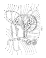
- FIG. 4 is an exploded view of the present invention.
- the upper frame 1 is comprised of two rear vertical members 1 c that terminate in backwardly extending rear handlebars 1 a , two front support members 1 d whose lower ends constitute upper vertical telescoping tubes 1 b , two lower connecting members 1 e to which the seat pad 5 a is attached with retention pins 7 , and two upper connecting members 1 f that connect the front support members 1 d to the rear vertical members 1 c .
- Each of the front support members 1 d is comprised of an upper vertical telescoping tube portion 1 b , a front handlebar 2 a , and a straight central portion that joins the vertical telescoping tube portion and the front handlebar.
- the angle between the vertical telescoping tube portion and the central portion is approximately one hundred thirty-five degrees, as is the angle between the front handlebar and the central portion.
- a rear push bar 2 is removably attached to the rear end of the two upper connecting members 1 f , as shown.
- a spring button 6 allows a person to remove the rear push bar 2 by depressing the spring button.
- a spring button 6 allows the front push bar 8 to be detached from the front handlebars 2 a .
- the front and rear handlebars 2 a , 1 a and the front and rear push bars 8 , 2 are all preferably covered with a foam grip. The foam grips are shown in FIG. 1 but removed from subsequent figure for clarity.
- the upper vertical telescoping tubes 1 b fit into the vertical part of the footrest frame mount 11 c , which forms a receptacle for receiving the upper vertical telescoping tube 1 b .
- the lower vertical telescoping tubes 11 . a extending from the rear of the lower frame 11 fit into receptacles formed by the lower ends of the rear vertical members 1 c (see also FIG. 8 ).
- a joinder bar 11 d connects the two arc-shaped members of the lower frame 11 .
- joinder bar 11 d terminates in a vertical tube 11 e that is held by brackets 11 f adjacent to the vertical part of the footrest frame mount 11 c and secured with a vertical retention pin 7 a .
- the joinder bar 11 d provides added stability to the lower frame 11 .
- FIG. 5A is a side view of the present invention shown with the wheelchair tipped backward so that the caster wheels are on the ground and the skids are up.
- FIG. 5B is a side view of the present invention shown with the wheelchair tipped forward so that the skids are on the ground and the caster wheels are up.
- the central axis of the front wheels 13 acts as a fulcrum about which the entire wheelchair rotates or tilts, depending on how the user places his or her weight. For example, when the user is sitting in the wheelchair, the caster wheels 12 will be in contact with the ground, as shown in FIG. 5A . When the user stands up and places his or her weight on the front push bar 8 , then the wheelchair is in the position shown in FIG.
- the user would lift up on the front push bar 8 so that the skids 15 are no longer in contact with the ground, take a step, and then place the skids 15 back down on the ground to prevent the wheelchair from moving.
- the length and arc of the lower frame 11 are configured so that when someone is sitting in the chair or when no one is sitting in the chair nor placing weight on the front push bar 8 , all four wheels (the two front wheels 13 and the two rear caster wheels 12 ) are in contact with the ground, and the skids 15 are above the ground. As soon as weight is placed onto the front push bar 8 , the chair tilts forward (around the central axis of the front wheels) so that the rear caster wheels 12 are above the ground and the skids 15 are in contact with the ground.
- FIG. 6 is a detail perspective view of the fall restraint assembly.
- the fall restraint assembly is comprised of a safety strap 9 , two loop members 9 a that encircle the front push bar 8 at its left and right ends, a clasp 9 b and a buckle 9 c .
- This figure clearly shows the loop members 9 a and the Y-shaped safety strap 9 , as well as the buckle 9 c on the underside of the seat frame 5 .
- the bottom part of the Y-shaped safety strap will be positioned between the user's two legs so that if he falters, he would not fall to the ground.
- the two strap segments that form the top part of the Y-shaped safety strap will cradle the user's upper body.
- FIGS. 7A, 7B and 7C show the brake assembly of the present invention in a braking, neutral and parking position, respectively.
- the brake assembly comprises a hand brake 10 , brake pad housing 10 a , brake pad 10 b , and brake cable 10 e .
- the user would squeeze on the hand brake 10 , pulling it toward the front support member 1 d . This action would cause the brake pad 10 b to engage with the front wheel 13 , as shown in FIG. 7A .
- the brake assembly will only remain in a braking position as long as the user is squeezing the hand brake 10 ; once pressure on the hand brake is released, the brake system will automatically return to the neutral position, disengaging the brake pad 10 b from the front wheel 13 ( FIG. 7B ).
- the brake assembly To put the brake assembly into a parking position, from the neutral position the user would push the hand brake 10 forward (away from the front support member 1 d ) until the hand brake audibly clicks, at which point the brake pad 10 b would engage with the front wheel 13 (as shown in FIG. 7C ) and remain in that position until the hand brake 10 is once again moved rearward.
- the brake pad 10 b is housed within the brake pad housing 10 a , and the brake pad 10 b is connected to the hand brake 10 via the brake cable 10 c.
- FIG. 8 is a side view of the present invention shown with the upper frame detached from the lower frame.
- the buckle 9 c is attached to the seat frame 5 via a downwardly protruding extension of the seat frame 5 , as shown. This is to facilitate access to the buckle 9 c .
- This figure clearly shows how the upper vertical telescoping tubes 1 b fit into the vertical part of the footrest frame mount 11 c and the lower vertical telescoping tubes 11 a fit into receptacles formed by the lower ends of the rear vertical members 1 c . Both the upper vertical telescoping tubes and the lower vertical telescoping tubes are secured in place with retention pins 7 .
- the fact that the upper frame 1 can be detached from the lower frame 11 by simply unlocking four retention pins and lifting the upper frame off of the lower frame is a distinct advantage of the present invention.
- FIG. 9 is a top perspective view of the present invention shown with the rear push bar detached from the upper frame.
- the rear push bar 2 is removably attached to the rear end of the two upper connecting members 1 f . Having the rear push bar 2 in addition to the rear handlebars 1 a makes it easier for a person to push the wheelchair from behind.
Landscapes
- Health & Medical Sciences (AREA)
- Life Sciences & Earth Sciences (AREA)
- Animal Behavior & Ethology (AREA)
- General Health & Medical Sciences (AREA)
- Public Health (AREA)
- Veterinary Medicine (AREA)
- Epidemiology (AREA)
- Pain & Pain Management (AREA)
- Physical Education & Sports Medicine (AREA)
- Rehabilitation Therapy (AREA)
- Rehabilitation Tools (AREA)
Abstract
A combination wheelchair-walker having an upper frame; a lower frame comprised of two arc-shaped members, in which each arch-shaped member is configured to extend from the front of the device to the back of the device, each of the two arc-shaped members having a front end and a rear end; two front wheels; two rear caster wheels, each of which is attached to the rear end of one of the two arc-shaped members; and two skids, each of which is attached to the front end of one of the two arc-shaped members. The upper frame is configured to be detached from the lower frame by unlocking four retention pins and lifting the upper frame off of the lower frame.
Description
The present invention relates generally to the field of wheelchairs, and more particularly, to a wheelchair that can also be used as a walker.
Current wheelchairs and walkers require the patient to switch between two pieces of equipment. As such, there is a need for a transitional medical device that would offer the functionality of both a wheelchair and a walker so that patients requiring the use of a wheelchair could work on developing or recovering their walking skills without leaving the wheelchair. A fear of falling often prevents individuals from attempting to use a walker. When individuals lose their mobility, they may become depressed as a result of their increased dependence on others. With a device that could be used both as a wheelchair and as a walker, more patients might be willing to attempt walking, which would improve their health and quality of life.
U.S. Pat. No. 3,584,890 (Presty, 1971) discloses a wheelchair with removable armrests that can be attached to the wheelchair frame in such a manner that the armrests act as extensible and removable supports that are engageable with the floor. In one embodiment, the supports include ground-engaging wheels, which allow the device to be used as a walker.
U.S. Pat. No. 3,719,390 (Haney, 1973) provides a wheelchair with a pivoting seat and an auxiliary frame that is coupled telescopically to the wheelchair main frame to allow the user to stand in an erect position. The auxiliary frame has a pair of vertically oriented legs that engage with the floor and that are connected by a lifting-bar. The purpose of the lifting-bar is to allow the operator to position the seat of the wheelchair relative to a toilet and hoist himself (with the use of the lifting-bar) into a standing position to gain access to the toilet.
U.S. Pat. No. 4,759,562 (Vinyard et al., 1988) discloses a kit for converting a wheelchair into a walker. The kit includes a seat for replacing the wheelchair bottom, a base for mounting the seat to the wheelchair, and an inverted U-shaped support bar. The support bar retains the patient between the sides of the wheelchair and seat.
U.S. Pat. No. 4,948,156 (Fortner, 1990) provides a frame that can be attached to a wheelchair to enable the user to move from a seated position in a wheelchair to a standing position without assistance from another person. The device incorporates a manually operated worm gear mechanism to facilitate lifting and prevent reverse movement of the lifting means when under load.
U.S. Pat. No. 5,320,122 (Jacobson, II et al., 1994) discloses a combined walker and wheelchair in which the seat assembly is slidably attached to the frame between a raised position and a lowered position. A spring causes the seat assembly to return to a raised position when weight is removed from the seat, and the seat pivotally returns to a lowered position when force (or weight) is applied to the seat. The frame assembly includes wheels that allow it to be moved along a floor surface. The chair is not self-propelled when the user is in the sitting position.
U.S. Pat. No. 5,419,571 (Vaughan, 1995) provides a collapsible wheelchair with a telescopically extending walker. In order to utilize the walker, the patient must push forward on the handrails and/or footrests to move each side of the walker forward until they are secured in an extended position. The patient would need assistance in order to convert the walker back into a wheelchair. The chair seat is configured so that it can be flipped up when not in use.
U.S. Pat. No. 5,451,193 (Pickard, 1995) discloses a combined wheelchair and walker with a braking device that is operatively associated with the seat. In a preferred embodiment, the brakes are not engaged with the wheels when the seat is in a raised position (walker mode). In an alternate embodiment, the brake is manually activated by the user whether the device is in wheelchair mode or walker mode.
U.S. Pat. No. 5,741,020 (Harroun, 1998) provides a collapsible combination chair-walker. The device includes a front rail and detachable safety strap. The chair has caster wheels but is not self-propelling (that is, it does not incorporate the larger rear wheels typically seen on a self-propelled wheelchair). The front rail is movable between a closed and locked position for normal operation and an open position for permitting ingress to and egress from the chair.
U.S. Pat. No. 6,338,493 (Wohlgemuth el al., 2002) discloses an apparatus that is convertible between a walker and a wheelchair. The rear pair of wheels is continuously engaged with the ground, and the front pair of wheels can be rotated upward (together with the footrests) to use the device as a walker. The seat also pivots upward when the device is in walker mode. The user cannot, however, simply stand up from the wheelchair seat into the walker; instead, the user would need to stand up without handrail assistance, turn around, and face in the other direction in order to use the walker. The user of this device could not simply sit down if he or she tired of walking.
U.S. Pat. No. 8,998,244 (Purdue, 2015) provides a wheelchair with a detachable walker. The walker is mechanically attached to the wheelchair by securing downwardly directed members into attachment sockets; according to the inventor, this procedure is performed by the caregiver (col. 2, lines 26-28). Presumably, a caregiver would be required to detach the walker from the wheelchair as well.
U.S. Patent Application Pub. No. 20110006494 (Walker) discloses a wheelchair with an extendable walker. The walker portion of the apparatus extends telescopically forward from the main wheelchair frame. As with Vaughan (referenced above), the user could not easily retract the walker back into the wheelchair without assistance. Furthermore, this device requires a mechanical conversion between wheelchair and walker modes, which the present invention does not.
It is an object of the present invention to provide a wheelchair that can also be used for walking with or without assistance. It is another object of the present invention to provide a wheelchair that is either self-propelled or that can be propelled by an aide. It is yet another object of the present invention to provide a wheelchair with safety features such as hand brakes, skids and safety straps to prevent falling and to alleviate the fear of falling. It is yet another object of the present invention to provide a wheelchair that can be disassembled for transport. Finally, it is an object of the present invention to provide a wheelchair that can be used as a walker without requiring the patient to stand up and physically convert the wheelchair into a walker.
The present invention is a combination wheelchair-walker device with a front and a back comprising: an upper frame; a lower frame comprised of two arc-shaped members, wherein each arch-shaped member is configured to extend from the front of the device to the back of the device, each of the two arc-shaped members having a front end and a rear end; two front wheels; two rear caster wheels, each of which is attached to the rear end of one of the two arc-shaped members; and two skids, each of which is attached to the front end of one of the two arc-shaped members. The invention preferably further comprises a seat frame, a seat pad, and a back pad.
In a preferred embodiment, the invention further comprises two footrests, each of which is attached to a footrest frame mount; wherein the footrest frame mount is comprised of a horizontal part and a vertical part joined together at a ninety-degree angle; and wherein the vertical part is attached to a wheel mount that is fixedly attached to one of the two front wheels. The invention preferably further comprises two push rails, each of which is spaced apart from and outwardly of one of the two front wheels; wherein each of the two front wheels comprises a front wheel frame; and wherein the push rail is connected to the front wheel frame of one of the two front wheels.
In a preferred embodiment, the invention further comprises a front push bar that is U-shaped; wherein each end of the U-shaped push bar terminates in a tube member; wherein each of the tube members fits telescopically into a front handlebar; and wherein the front handlebars extend forwardly from the upper frame. Preferably, the invention further comprises a fall restraint assembly; wherein the fall restraint assembly comprises a safety strap, two loop members that encircle the front push bar, a clasp and a buckle; wherein the safety strap is Y-shaped and extends from the two loop members to a central point where the safety strap continues as a single strap to the clasp; and wherein the buckle is located on an underside of the seat frame, and the claps fits into the buckle.
In a preferred embodiment, the upper frame is comprised of two rear vertical members that terminate in backwardly extending rear handlebars, two front support members with lower ends that constitute upper vertical telescoping tubes, two lower connection members to which the seat pad is attached, and two upper connecting members that connect the front support members to the rear vertical members; and wherein each of the front support members is comprised of an upper vertical telescoping tube portion, a front handlebar, and a straight central portion that joins the vertical telescoping tube portion and the front handlebar. Preferably, the invention further comprises two armrests that are situated on top of the upper connecting members. The invention preferably further comprises a rear push bar that is removably attached to a rear end of each of the two upper connecting members.
In a preferred embodiment, the invention further comprising two footrests, each of which is attached to a footrest frame mounts; wherein the footrest frame mount is comprised of a horizontal part and a vertical part joined together at a ninety-degree angle; wherein the vertical part of the footrest frame mount is attached to a wheel mount that is fixedly attached to one of the two front wheels; wherein the upper vertical telescoping tubes are configured to fit into the vertical part of the footrest frame mount; wherein the vertical part of the footrest frame mount is configured to form a receptacle for receiving the upper vertical telescoping tube; and wherein a lower vertical telescoping tube extends upwardly from a rear end of each of the two arc-shaped members and is configured to fit into a receptacle formed by a lower end of one of the two rear vertical members. Preferably, the invention further comprises a joinder bar that connects the two arc-shaped members; wherein each end of the joinder bar terminates in a vertical tube that is secured adjacent to the vertical part of the footrest frame mount.
In a preferred embodiment, the invention further comprises a brake assembly; wherein the brake assembly comprises a hand brake, a brake pad housing, a brake pad, and a brake cable. In another preferred embodiment, the upper frame is configured to be detached from the lower frame by unlocking four retention pins and lifting the upper frame off of the lower frame, two of the four retention pins being used to secure the upper vertical telescoping tubes into the vertical part of the footrest frame mounts, and the remaining two of the four retention pins being used to secure the lower vertical telescoping tubes into the receptacles formed by the lower ends of the rear vertical members.
-
- 1 Upper frame
- 1 a Rear handlebar
- 1 b Upper vertical telescoping tube
- 1 c Rear vertical member
- 1 d Front support member
- 1 e Lower connecting member
- 1 f Upper connecting member
- 2 Rear push bar
- 2 a Front handlebar
- 3 Armrest
- 4 Seat back pad
- 5 Seat frame
- 5 a Seat pad
- 6 Spring button
- 7 Retention pin
- 7 a Vertical retention pin
- 8 Front push bar
- 8 a Telescoping member (long)
- 8 b Telescoping member (short)
- 9 Fall restraint safety strap
- 9 a Loop member
- 9 b Clasp
- 9 c Buckle
- 10 Hand brake
- 10 a Brake pad housing
- 10 b Brake pad
- 10 c Brake cable
- 11 Lower frame
- 11 a Lower vertical telescoping tube
- 11 b Wheel mount
- 11 c Footrest frame mount
- 11 d Joinder bar
- 11 e Vertical tube
- 11 f Bracket
- 12 Rear caster wheel
- 13 Front wheel
- 13 a Front wheel push rail
- 13 b Front wheel bolt
- 14 Footrest
- 15 Skid
When the chair is assembled, armrests 3 are situated on top of the upper connecting members 1 f. A rear push bar 2 is removably attached to the rear end of the two upper connecting members 1 f, as shown. A spring button 6 allows a person to remove the rear push bar 2 by depressing the spring button. Similarly, a spring button 6 allows the front push bar 8 to be detached from the front handlebars 2 a. The front and rear handlebars 2 a, 1 a and the front and rear push bars 8, 2 are all preferably covered with a foam grip. The foam grips are shown in FIG. 1 but removed from subsequent figure for clarity.
As shown in this figure, when the chair is assembled, the upper vertical telescoping tubes 1 b fit into the vertical part of the footrest frame mount 11 c, which forms a receptacle for receiving the upper vertical telescoping tube 1 b. Similarly, the lower vertical telescoping tubes 11.a extending from the rear of the lower frame 11 fit into receptacles formed by the lower ends of the rear vertical members 1 c (see also FIG. 8 ). A joinder bar 11 d connects the two arc-shaped members of the lower frame 11. Each end of the joinder bar 11 d terminates in a vertical tube 11 e that is held by brackets 11 f adjacent to the vertical part of the footrest frame mount 11 c and secured with a vertical retention pin 7 a. The joinder bar 11 d provides added stability to the lower frame 11.
The length and arc of the lower frame 11 are configured so that when someone is sitting in the chair or when no one is sitting in the chair nor placing weight on the front push bar 8, all four wheels (the two front wheels 13 and the two rear caster wheels 12) are in contact with the ground, and the skids 15 are above the ground. As soon as weight is placed onto the front push bar 8, the chair tilts forward (around the central axis of the front wheels) so that the rear caster wheels 12 are above the ground and the skids 15 are in contact with the ground.
To put the brake assembly into a parking position, from the neutral position the user would push the hand brake 10 forward (away from the front support member 1 d) until the hand brake audibly clicks, at which point the brake pad 10 b would engage with the front wheel 13 (as shown in FIG. 7C ) and remain in that position until the hand brake 10 is once again moved rearward. Note that the brake pad 10 b is housed within the brake pad housing 10 a, and the brake pad 10 b is connected to the hand brake 10 via the brake cable 10 c.
Although the preferred embodiment of the present invention has been shown and described, it will be apparent to those skilled in the art that many changes and modifications may be made without departing from the invention in its broader aspects. The appended claims are therefore intended to cover all such changes and modifications as fall within the true spirit and scope of the invention.
Claims (13)
1. A combination wheelchair-walker device with a front and a back comprising:
(a) an upper frame;
(b) a lower frame comprised of two upwardly curved arc-shaped members, wherein each arc-shaped member is configured to extend from the front of the device to the back of the device, each of the two arc-shaped members having a front end and a rear end;
(c) two front wheels, wherein at least one of the two front wheels are directly attached to at least one footrest frame mount;
(d) two rear caster wheels, each of which is attached to the rear end of one of the two arc-shaped members; and
(e) two skids, each of which is attached to the front end of one of the two arc-shaped members.
2. The combination wheelchair-walker device of claim 1 , further wherein the at least one footrest frame mount comprises two footrest frame mounts, wherein a footrest is attached to each of the footrest frame mounts; and wherein each footrest frame mount is comprised of a horizontal part and a vertical part joined together at a ninety-degree angle; and
wherein the vertical part is attached to a wheel mount that is fixedly attached to one of the two front wheels.
3. The combination wheelchair-walker device of claim 2 , further comprising a joinder bar that connects the two arc-shaped members;
wherein each end of the joinder bar terminates in a vertical tube that is secured adjacent to the vertical part of the footrest frame mount.
4. The combination wheelchair-walker device of claim 1 , further comprising a seat frame, a seat pad, and a back pad.
5. The combination wheelchair-walker device of claim 4 , further comprising a front push bar that is U-shaped;
wherein each end of the U-shaped push bar terminates in a tube member;
wherein each of the tube members fits telescopically into a front handlebar; and
wherein the front handlebars extend forwardly from the upper frame.
6. The combination wheelchair-walker device of claim 5 , further comprising a fall restraint assembly;
wherein the fall restraint assembly comprises a safety strap, two loop members that encircle the front push bar, a clasp and a buckle;
wherein the safety strap is Y-shaped and extends from the two loop members to a central point where the safety strap continues as a single strap to the clasp; and
wherein the buckle is located on an underside of the seat frame, and the claps fits into the buckle.
7. The combination wheelchair-walker device of claim 4 , wherein the upper frame is comprised of two rear vertical members that terminate in backwardly extending rear handlebars, two front support members with lower ends that constitute upper vertical telescoping tubes, two lower connection members to which the seat pad is attached, and two upper connecting members that connect the front support members to the rear vertical members; and
wherein each of the front support members is comprised of an upper vertical telescoping tube portion, a front handlebar, and a straight central portion that joins the vertical telescoping tube portion and the front handlebar.
8. The combination wheelchair-walker device of claim 7 , further comprising two armrests that are situated on top of the upper connecting members.
9. The combination wheelchair-walker device of claim 7 , further comprising a rear push bar that is removably attached to a rear end of each of the two upper connecting members.
10. The combination wheelchair-walker device of claim 7 , further comprising two footrests, each of which is attached to a footrest frame mounts;
wherein the footrest frame mount is comprised of a horizontal part and a vertical part joined together at a ninety-degree angle;
wherein the vertical part of the footrest frame mount is attached to a wheel mount that is fixedly attached to one of the two front wheels;
wherein the upper vertical telescoping tubes are configured to fit into the vertical part of the footrest frame mount;
wherein the vertical part of the footrest frame mount is configured to form a receptacle for receiving the upper vertical telescoping tube; and
wherein a lower vertical telescoping tube extends upwardly from a rear end of each of the two arc-shaped members and is configured to fit into a receptacle formed by a lower end of one of the two rear vertical members.
11. The combination wheelchair-walker device of claim 10 , wherein the upper frame is configured to be detached from the lower frame by unlocking four retention pins and lifting the upper frame off of the lower frame, two of the four retention pins being used to secure the upper vertical telescoping tubes into the vertical part of the footrest frame mounts, and the remaining two of the four retention pins being used to secure the lower vertical telescoping tubes into the receptacles formed by the lower ends of the rear vertical members.
12. The combination wheelchair-walker device of claim 1 , further comprising a brake assembly;
wherein the brake assembly comprises a hand brake, a brake pad housing, a brake pad, and a brake cable.
13. The combination wheelchair-walker device of claim 1 , further comprising two push rails, each of which is spaced apart from and outwardly of one of the two front wheels;
wherein each of the two front wheels comprises a front wheel frame; and
wherein the push rail is connected to the front wheel frame of one of the two front wheels.
Priority Applications (1)
| Application Number | Priority Date | Filing Date | Title |
|---|---|---|---|
| US15/657,179 US9962303B1 (en) | 2017-07-23 | 2017-07-23 | Combination wheelchair-walker device |
Applications Claiming Priority (1)
| Application Number | Priority Date | Filing Date | Title |
|---|---|---|---|
| US15/657,179 US9962303B1 (en) | 2017-07-23 | 2017-07-23 | Combination wheelchair-walker device |
Publications (1)
| Publication Number | Publication Date |
|---|---|
| US9962303B1 true US9962303B1 (en) | 2018-05-08 |
Family
ID=62046575
Family Applications (1)
| Application Number | Title | Priority Date | Filing Date |
|---|---|---|---|
| US15/657,179 Active US9962303B1 (en) | 2017-07-23 | 2017-07-23 | Combination wheelchair-walker device |
Country Status (1)
| Country | Link |
|---|---|
| US (1) | US9962303B1 (en) |
Cited By (8)
| Publication number | Priority date | Publication date | Assignee | Title |
|---|---|---|---|---|
| CN109350466A (en) * | 2018-12-13 | 2019-02-19 | 南通大学附属医院 | A walker for cardiothoracic surgery nursing |
| US10399588B1 (en) | 2018-08-31 | 2019-09-03 | Albert Gallatin Grantham, IV | Retractable wheelchair handlebars |
| US20200206067A1 (en) * | 2018-12-28 | 2020-07-02 | Participant Assistive Products | Modular mobility systems |
| US11633322B1 (en) * | 2022-07-08 | 2023-04-25 | Leo Harden | Convertible wheelchair |
| US20230190567A1 (en) * | 2021-12-17 | 2023-06-22 | Pamela Hill-Williams | Go along sturdy walker |
| US11963921B2 (en) | 2022-07-08 | 2024-04-23 | Leo Harden | Convertible walker |
| US12121482B1 (en) | 2024-01-04 | 2024-10-22 | Naun Galvan | Apparatus for coupling a wheelchair and a walker |
| US20240415724A1 (en) * | 2023-05-31 | 2024-12-19 | Xianhe Yang | Four-wheel walker with large front wheel and small rear wheel |
Citations (35)
| Publication number | Priority date | Publication date | Assignee | Title |
|---|---|---|---|---|
| US865514A (en) * | 1906-12-04 | 1907-09-10 | Paul Muellenmeister | Sick and invalid carriage. |
| US1739260A (en) * | 1929-12-10 | Invalid chair | ||
| US2427161A (en) * | 1944-11-01 | 1947-09-09 | Colson Corp | Invalid chair |
| US2694437A (en) * | 1952-06-30 | 1954-11-16 | William P Glaser | Combination wheel chair and stretcher |
| US2701005A (en) * | 1954-06-23 | 1955-02-01 | Nat Foundation For Infantile P | Curb climbing wheel chair |
| US3111331A (en) * | 1962-03-05 | 1963-11-19 | Burton H Locke | Stair-climbing wheel chair |
| US3216738A (en) * | 1963-05-01 | 1965-11-09 | Charles R Bockus | Chairs for non-ambulatory persons |
| US3584890A (en) | 1969-04-01 | 1971-06-15 | Delta Physical Therapy Associa | Convertible wheelchair construction |
| US3719390A (en) | 1971-01-22 | 1973-03-06 | M Haney | Wheel chair |
| US4268054A (en) * | 1979-06-27 | 1981-05-19 | Twitchell Brent L | Child transport vehicle |
| US4620714A (en) * | 1984-05-23 | 1986-11-04 | Davis Daniel W | Ambulatory wheelstand |
| US4744578A (en) * | 1987-02-09 | 1988-05-17 | Luconex, Inc. | User inclinable prone stander type wheelchair |
| US4759562A (en) | 1986-05-09 | 1988-07-26 | Vinyard Lillian L | Walker conversions for wheel chairs |
| US4948156A (en) | 1989-03-13 | 1990-08-14 | Legg-On | Standing lift and support for wheelchair user |
| US5020817A (en) * | 1987-10-30 | 1991-06-04 | Rober K. Leib | Wheelchair |
| US5286046A (en) * | 1991-11-25 | 1994-02-15 | Homecrest Industries Incorporated | Geriatric chair |
| US5320122A (en) | 1991-07-03 | 1994-06-14 | II Julius H. Jacobson | Combined walker and wheelchair |
| US5419571A (en) | 1993-03-08 | 1995-05-30 | Vaughan; Jack N. | Wheel chair with provisions for patient walker |
| US5451193A (en) | 1992-08-12 | 1995-09-19 | Pickard; Raleigh H. | Combined wheelchair and walker |
| US5702326A (en) * | 1996-05-21 | 1997-12-30 | Versatex Inc. | Walking assistance device |
| US5741020A (en) | 1994-08-31 | 1998-04-21 | Mary M. Harroun | Collapsable combination chair walker |
| US6024369A (en) * | 1998-01-05 | 2000-02-15 | Bernard Goldstein | Specialized wheelchair for a paraplegic fencer |
| US6276704B1 (en) * | 1997-09-23 | 2001-08-21 | Charles J. Suiter | Adjustable wheelchair having a tilting and reclining seat |
| US6338493B1 (en) | 2000-04-19 | 2002-01-15 | Eli Wohlgemuth | Walker chair |
| US6484829B1 (en) * | 2000-07-03 | 2002-11-26 | Kenneth Ray Cox | Battery powered stair-climbing wheelchair |
| US6733018B2 (en) * | 2002-01-24 | 2004-05-11 | Eli Razon | Adjustable leg support and seated to stand up walker |
| US20040135326A1 (en) * | 2001-03-09 | 2004-07-15 | Goran Palmers | Device for facilitating driving a rollable walker and a rollable walker provided with such a device |
| JP2004202264A (en) * | 2004-03-05 | 2004-07-22 | Kazuo Saito | Wheelchair |
| US6902178B2 (en) * | 2003-04-28 | 2005-06-07 | O-Matic Corp. | Transport chair for a patient |
| US20070012526A1 (en) * | 2005-07-18 | 2007-01-18 | Steven Holub | Wheelchair inboard disk brakes |
| US20110006494A1 (en) | 2009-07-13 | 2011-01-13 | Evaret Walker | Wheelchair with extendable walker |
| US8151812B2 (en) * | 2010-07-02 | 2012-04-10 | Eli Razon | Sit down and stand up walker with seat assembly |
| US20140300071A1 (en) | 2011-11-18 | 2014-10-09 | Carole PURDUE | Wheelchair with detachable walker |
| US8864151B1 (en) * | 2010-10-29 | 2014-10-21 | Evolution Technologies Inc. | Foldable walker apparatus |
| US9398988B1 (en) * | 2015-06-01 | 2016-07-26 | Jackdrive™ Wheelchair System, Llc. | Human powered wheelchair with jackdrive™ propulsion system |
-
2017
- 2017-07-23 US US15/657,179 patent/US9962303B1/en active Active
Patent Citations (36)
| Publication number | Priority date | Publication date | Assignee | Title |
|---|---|---|---|---|
| US1739260A (en) * | 1929-12-10 | Invalid chair | ||
| US865514A (en) * | 1906-12-04 | 1907-09-10 | Paul Muellenmeister | Sick and invalid carriage. |
| US2427161A (en) * | 1944-11-01 | 1947-09-09 | Colson Corp | Invalid chair |
| US2694437A (en) * | 1952-06-30 | 1954-11-16 | William P Glaser | Combination wheel chair and stretcher |
| US2701005A (en) * | 1954-06-23 | 1955-02-01 | Nat Foundation For Infantile P | Curb climbing wheel chair |
| US3111331A (en) * | 1962-03-05 | 1963-11-19 | Burton H Locke | Stair-climbing wheel chair |
| US3216738A (en) * | 1963-05-01 | 1965-11-09 | Charles R Bockus | Chairs for non-ambulatory persons |
| US3584890A (en) | 1969-04-01 | 1971-06-15 | Delta Physical Therapy Associa | Convertible wheelchair construction |
| US3719390A (en) | 1971-01-22 | 1973-03-06 | M Haney | Wheel chair |
| US4268054A (en) * | 1979-06-27 | 1981-05-19 | Twitchell Brent L | Child transport vehicle |
| US4620714A (en) * | 1984-05-23 | 1986-11-04 | Davis Daniel W | Ambulatory wheelstand |
| US4759562A (en) | 1986-05-09 | 1988-07-26 | Vinyard Lillian L | Walker conversions for wheel chairs |
| US4744578A (en) * | 1987-02-09 | 1988-05-17 | Luconex, Inc. | User inclinable prone stander type wheelchair |
| US5020817A (en) * | 1987-10-30 | 1991-06-04 | Rober K. Leib | Wheelchair |
| US4948156A (en) | 1989-03-13 | 1990-08-14 | Legg-On | Standing lift and support for wheelchair user |
| US5320122A (en) | 1991-07-03 | 1994-06-14 | II Julius H. Jacobson | Combined walker and wheelchair |
| US5286046A (en) * | 1991-11-25 | 1994-02-15 | Homecrest Industries Incorporated | Geriatric chair |
| US5451193A (en) | 1992-08-12 | 1995-09-19 | Pickard; Raleigh H. | Combined wheelchair and walker |
| US5419571A (en) | 1993-03-08 | 1995-05-30 | Vaughan; Jack N. | Wheel chair with provisions for patient walker |
| US5741020A (en) | 1994-08-31 | 1998-04-21 | Mary M. Harroun | Collapsable combination chair walker |
| US5702326A (en) * | 1996-05-21 | 1997-12-30 | Versatex Inc. | Walking assistance device |
| US6276704B1 (en) * | 1997-09-23 | 2001-08-21 | Charles J. Suiter | Adjustable wheelchair having a tilting and reclining seat |
| US6024369A (en) * | 1998-01-05 | 2000-02-15 | Bernard Goldstein | Specialized wheelchair for a paraplegic fencer |
| US6338493B1 (en) | 2000-04-19 | 2002-01-15 | Eli Wohlgemuth | Walker chair |
| US6484829B1 (en) * | 2000-07-03 | 2002-11-26 | Kenneth Ray Cox | Battery powered stair-climbing wheelchair |
| US20040135326A1 (en) * | 2001-03-09 | 2004-07-15 | Goran Palmers | Device for facilitating driving a rollable walker and a rollable walker provided with such a device |
| US6733018B2 (en) * | 2002-01-24 | 2004-05-11 | Eli Razon | Adjustable leg support and seated to stand up walker |
| US6902178B2 (en) * | 2003-04-28 | 2005-06-07 | O-Matic Corp. | Transport chair for a patient |
| JP2004202264A (en) * | 2004-03-05 | 2004-07-22 | Kazuo Saito | Wheelchair |
| US20070012526A1 (en) * | 2005-07-18 | 2007-01-18 | Steven Holub | Wheelchair inboard disk brakes |
| US20110006494A1 (en) | 2009-07-13 | 2011-01-13 | Evaret Walker | Wheelchair with extendable walker |
| US8151812B2 (en) * | 2010-07-02 | 2012-04-10 | Eli Razon | Sit down and stand up walker with seat assembly |
| US8864151B1 (en) * | 2010-10-29 | 2014-10-21 | Evolution Technologies Inc. | Foldable walker apparatus |
| US20140300071A1 (en) | 2011-11-18 | 2014-10-09 | Carole PURDUE | Wheelchair with detachable walker |
| US8998244B2 (en) | 2011-11-18 | 2015-04-07 | Carole PURDUE | Wheelchair with detachable walker |
| US9398988B1 (en) * | 2015-06-01 | 2016-07-26 | Jackdrive™ Wheelchair System, Llc. | Human powered wheelchair with jackdrive™ propulsion system |
Cited By (10)
| Publication number | Priority date | Publication date | Assignee | Title |
|---|---|---|---|---|
| US10399588B1 (en) | 2018-08-31 | 2019-09-03 | Albert Gallatin Grantham, IV | Retractable wheelchair handlebars |
| CN109350466A (en) * | 2018-12-13 | 2019-02-19 | 南通大学附属医院 | A walker for cardiothoracic surgery nursing |
| CN109350466B (en) * | 2018-12-13 | 2021-11-26 | 南通大学附属医院 | Walking aid for cardiothoracic surgery nursing |
| US20200206067A1 (en) * | 2018-12-28 | 2020-07-02 | Participant Assistive Products | Modular mobility systems |
| US11839584B2 (en) * | 2018-12-28 | 2023-12-12 | Participant Assistive Products | Modular mobility systems |
| US20230190567A1 (en) * | 2021-12-17 | 2023-06-22 | Pamela Hill-Williams | Go along sturdy walker |
| US11633322B1 (en) * | 2022-07-08 | 2023-04-25 | Leo Harden | Convertible wheelchair |
| US11963921B2 (en) | 2022-07-08 | 2024-04-23 | Leo Harden | Convertible walker |
| US20240415724A1 (en) * | 2023-05-31 | 2024-12-19 | Xianhe Yang | Four-wheel walker with large front wheel and small rear wheel |
| US12121482B1 (en) | 2024-01-04 | 2024-10-22 | Naun Galvan | Apparatus for coupling a wheelchair and a walker |
Similar Documents
| Publication | Publication Date | Title |
|---|---|---|
| US9962303B1 (en) | Combination wheelchair-walker device | |
| US6338493B1 (en) | Walker chair | |
| US3104112A (en) | Stair climbing wheel chair | |
| US4572501A (en) | Exercise device for attachment to a wheelchair | |
| US6651994B2 (en) | Walker with movable carry basket | |
| CA2097170C (en) | Mobility aid for physically disabled people | |
| US4744578A (en) | User inclinable prone stander type wheelchair | |
| US6412795B1 (en) | Assembly of nestable wheelchairs and wheelchair for use in such an assembly | |
| US4342465A (en) | Safety walker | |
| US2596055A (en) | Detachable wheel chair walking apparatus | |
| US20050156395A1 (en) | Rolling walker with arm rest platforms | |
| US5884929A (en) | Invalid transport | |
| US5058912A (en) | Combination chair/walker | |
| US7673888B2 (en) | Combined wheelchair, walker, and sitting chair | |
| US5378215A (en) | Rehabilitation apparatus for ambulatory patients | |
| US20080185797A1 (en) | Armrest rolling walker with removable utility tray | |
| US7364184B2 (en) | Mobility assist devices | |
| US4695072A (en) | Athlete carrier | |
| US20100140893A1 (en) | Walker apparatus | |
| US6220620B1 (en) | Wheeled height-adjustable rehabilitation chair | |
| US8177248B2 (en) | Wheelchair with manual lift and methods of using same | |
| JP2001321404A (en) | Wheelchair combined with walking frame | |
| GB2127705A (en) | Invalid's walking frame | |
| WO1998015250A1 (en) | A transfer aid | |
| CN119174692A (en) | Walking frame with seat and backrest |
Legal Events
| Date | Code | Title | Description |
|---|---|---|---|
| STCF | Information on status: patent grant |
Free format text: PATENTED CASE |
|
| MAFP | Maintenance fee payment |
Free format text: PAYMENT OF MAINTENANCE FEE, 4TH YR, SMALL ENTITY (ORIGINAL EVENT CODE: M2551); ENTITY STATUS OF PATENT OWNER: SMALL ENTITY Year of fee payment: 4 |
|
| MAFP | Maintenance fee payment |
Free format text: PAYMENT OF MAINTENANCE FEE, 8TH YR, SMALL ENTITY (ORIGINAL EVENT CODE: M2552); ENTITY STATUS OF PATENT OWNER: SMALL ENTITY Year of fee payment: 8 |