US995988A - Coin-controlled ticket-vending machine. - Google Patents
Coin-controlled ticket-vending machine. Download PDFInfo
- Publication number
- US995988A US995988A US47329009A US1909473290A US995988A US 995988 A US995988 A US 995988A US 47329009 A US47329009 A US 47329009A US 1909473290 A US1909473290 A US 1909473290A US 995988 A US995988 A US 995988A
- Authority
- US
- United States
- Prior art keywords
- wheel
- plate
- shaft
- arm
- coin
- Prior art date
- Legal status (The legal status is an assumption and is not a legal conclusion. Google has not performed a legal analysis and makes no representation as to the accuracy of the status listed.)
- Expired - Lifetime
Links
- 239000011111 cardboard Substances 0.000 description 18
- 238000005520 cutting process Methods 0.000 description 8
- 230000007246 mechanism Effects 0.000 description 7
- 230000003534 oscillatory effect Effects 0.000 description 6
- 230000010355 oscillation Effects 0.000 description 4
- 230000002093 peripheral effect Effects 0.000 description 4
- 230000005484 gravity Effects 0.000 description 3
- 239000011435 rock Substances 0.000 description 3
- 238000010008 shearing Methods 0.000 description 3
- 241000220010 Rhode Species 0.000 description 2
- 240000007582 Corylus avellana Species 0.000 description 1
- 241000283986 Lepus Species 0.000 description 1
- 239000003086 colorant Substances 0.000 description 1
- 238000010276 construction Methods 0.000 description 1
- 230000003028 elevating effect Effects 0.000 description 1
- 230000008676 import Effects 0.000 description 1
- OWFXIOWLTKNBAP-UHFFFAOYSA-N isoamyl nitrite Chemical compound CC(C)CCON=O OWFXIOWLTKNBAP-UHFFFAOYSA-N 0.000 description 1
- 239000000123 paper Substances 0.000 description 1
- 239000000126 substance Substances 0.000 description 1
Images


Classifications
-
- B—PERFORMING OPERATIONS; TRANSPORTING
- B41—PRINTING; LINING MACHINES; TYPEWRITERS; STAMPS
- B41F—PRINTING MACHINES OR PRESSES
- B41F17/00—Printing apparatus or machines of special types or for particular purposes, not otherwise provided for
Definitions
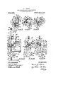
- Figure 1 is a front elevation of my improved ticket vending machine, asv seen on line .r-w of Fig. 3.
- Fig. 2 is a plan view of the cardboard strip, which is to be printed, cut and delivered by said machine.
- Fig. 3 is a view of said machine, partly in elevation and partly in section as seen on line a-e of Fig. 1.
- Fig. ⁇ 4 is a view in elevation of the parts of said machine, seen on line jz/-jl/ of Fig. 3.
- Fig. 5 is a view in elevation of a ratchet wheel and pawl, constituting one of the sto mechanisms of my said invention.
- Fig. 6 1s an elevation of the sprocket ring, which is a part of the feeding mechanism.
- Fig. 6 1s an elevation of the sprocket ring, which is a part of the feeding mechanism.
- FIG. 7 is a front elevation of the cabinet and front plate of my machine, the interior mechanism being indicated by dotted lines.
- Fig. 8 shows in side elevation the coin-actuated device, which is the motive apparatus of said machine, as seen in its normal inoperative position.
- Fig. 9 is a front elevation of said coin device, as seen in its normal inoperative position, the section being yonline o-#v' of Fig. 8.
- Fig. 10 is a front elevation of said device, as seen on line o-fv of Fig. S at the end of the cutting operation, when the coin is discharged therefrom.
- Fig. 10 is a front elevation of said device, as seen on line o-fv of Fig. S at the end of the cutting operation, when the coin is discharged therefrom.
- FIG. 11 shows an elevation of the cutting'mechanismfor dividing said indicate like vcardl'iorird strip into separate ticketsto be delivered, said mechanism being represented in its normal inoperative position, as seen on line fw-w of Fig. 1.
- Fig. 12 is an elevation of the cutting mechanism, on said line fw-w as seen at the instant-when the cutter is to begin its said operation.
- Fig.l 13 is an eleration of the cutting mechanism as seen on said line w-fw at. the instant when the cutter has finished its operation and the ticket has been completely severed from the cardboard strip.
- My invention relates to coin-contro1led Specification of Letters Patent. Patented J une 20, 1911, Application med January ao, 1909.
- vending machines adapted to print, cut and deliver tickets; and it consists of the novel construction and combination of the several parts as hereinafter described and set forth in the claims.
- FIG. 1 designates the front plate of the machine, and 2 the back plate thereof.
- a cabinet or case 3 has the hasel 4 and a top or cover 5.
- the front side 6 of the case 3 is detachable, and is fastened by a lock 7, whose bolt 8 enters a. mortise in the top or cover 5 an ⁇ d is operated by a key inserted in the key hole 9.
- the front plate 1 has a window or aperture 10, through which the ticket is delivered upon a shelf 11.
- the front side 6 of the cabinet is cut to givearectangular opening, as indicated by solid lines in Fig. 7, behind which aperture, so made, the front plate 1 extends and is secured.
- a crank or oper ating handle 12 extends through the front plate.
- the crank 12' has a knob 13.
- the stop pin 14., 1, limits the i pward movement of the crank l2, and the stop pin 15, projecting from the front plate 1, limits the downward movement. of the crank 12.
- the extent of the movement of the crank 12 is 72, that is, one-fifth of one revolution.
- the front plate 1 has a coin aperture 16, as shown in Fig. 7.
- the back plate 2 has the feet 17, upon which the machine is supported wit-hin the ease
- a standard or post 18 has a fianged hase 19 and is mounted upon the upper portion of the back plate 2 and secured thereto by bolts 20.
- the up er end of the ost or standard 18 is bent ike an inverte L, as represented by dotted line 21 in Fig. 1, and supports two parallel bars or arms 22, 23, the latter being shown in Fig. 1, as broken olf, -near one end thereof, in order to 'represent such parallel arrangement.
- the said bars 22, 23 and the said horizontal portion of the standard 18 have each a tubular hub or bearing 24.
- a fixed shaft 25 extends through said three bearings, 24 and is secured and held from rotation therein by a set screw 26.
- a spool 27 is loosely mounted on the shaft 25, between the arms 22, 23, and a. strip of cardboard is coiled upon the spoolV 27, as shown at 28.
- a weight/ed arm 29, has a bearing 30, secured thereto at one end by means of the screws 31, and a pivot rejecting from the front plateloosely mounted on the shaft 91, and is normally held in forcible contact with the card board strip (hereinafter described) upon the sprocket wheel 64, by means of the spring 105, one end of which is hooked into a hole in said arm 103, and the opposite end of which is looped upon a pin or stud 106 on the boss or journal 100.
- a collar 107 which is fast upon the shaft 99, has a radial arm 108, Whose outer end is formed with an eye.
- the lower end of the link bar 61 is hooked in saideye in order to engage with the radial arm 108.
- a collar 109 is mounted on the shaft 99 and is held fast thereon by means of a set screw 110.
- An integral wedge-shaped cani 111 upon the collar 109 has an oscillatory movement with the shaft 99.
- Said cam cooperateswith a toe 112, which extends from the stop pawl 92, as illustrated in Figs. 1 and 4.
- a printing wheel 113 has a hub 114 and is mounted on a shaft 115.
- the shaft 115 has a head 116 at its front end, and its rear end is threaded and passes through the back plate Vand is held in position by means of a nut 117.
- the shaft 115 is shouldered, as shown at 118 in Fig. 3.
- a Ilat circular ring 119 is fastened by lscrews 120 to the front face of the printing wheel 113.
- the printing wheel 113 is driven by a gear 121, which is fastened by screws 122, passing into said wheel.
- the sprockets 79 engage with said wheel in sockets 123 thereof, as shown in Figs. 1 and 3.
- the type upon the Wheel 113 is shown at ⁇ 124 in Fig. 3. It is in the form of a stereotyped strip, which has beveled edges, as s own.
- the ring 119 has its outer edge provided with a beveled lip to engage the front edge ofthe type strip 124, as seen in Fig.
- the printingr wheel 113 has a rear flange 125 provided with a cam edge, and also cairries ar cam plate 126 concentric therewith and fastened by the screws 122 to said wheel.
- An arm 127 has a hub 128, by which it is mounted loosely on the rod or shaft 88.
- An arm 129 has a hub 1.30, by which it is mounted loosely onthe-rod or shaft 90, as seen in Figs. 1 and 4.
- the arm 127 has at its outer end a stud or pin 131, on which a roller 132 is rotatably mounted, said roller traveling along the peri hery of the cam 125.
- the arm 129 has at ,lts outer end a stud or pin 133, on which a roller 134 is rotatably mounted to travel along the )eriphery of the earn plate 126.
- the arm 1217 has a post 135 "hanger 149.
- a spiral spring 137 has its ends. hooked into said posts 135 and 136, respective-ly. l
- An ihk roller 138 is rotatably mounted on the stud or pin 131 (which is preferably a screw, having a screw head 139) and an ink roller 140 is rotatably mounted on the stud or in 133 (which is preferably a screw, havlng a screw head 141).
- the strip of card board which is to be rinted,cut and delivered by this machine 1s,designated as 1.42 and is shown in plan view in Fig. 2. On each edge it has a series of equi-spaced semicircular. notches 143; those of one edge being exactly opposite those of the otheredge seriatm.
- the dotted lines in Fig. 2 denote the lines of the cutting of the strip 142 into separate tickets, such as that marked 80 in Fig. 13.
- a guide Wheel 144 is rotatably mounted on the rod or shaft 87 and is provided with two opposite annular flanges, as shown in Fig. 1.
- a bracket 145 projects from the back plate 2.
- a curved spring 146 is fastened by screws 147 to the bracket 145 and is bent to conform to the curvature of the wheel 144. Said spring extends between the flanges of the wheel 144 and serves to press the strip 142 to the wheel, as illustrated in Fig. 1.
- a bracket 148 extends from the back plate 2 and has a downwardly extending end or hanger 149.
- a guide plate 150 is fastenedV by screws 151. upon the bracket 148 and has a passage through it for the feed of the strip of cardboard to the cutting mechanism, as shown in Figs. 1, 11 and 12.
- a fixed blade 152 is fastened by screws 153 to the hanger 149.4
- a movable blade 154 is mounted on a screw pivot 155, which passes into the The blade 154 has the recess 156 and shoulder 157.
- the beveled sharp edge of the blade 154 h as a shearing contact with the fixed blade 152, as shown.
- the shaft 99 is a sleeve or tube 158 held thereon by a set screw 159.
- a radial arm 160 extends from the sleeve or tube 158.
- a link bar 161 is pivotally mounted on the end of the arm 160, as shown at 162.
- the link bar 161 has an eye 163 and the back plate2has a stud or pin 164.
- Aspiral spring 165 is secured at one end to the eye 163 and at its opposite end to the stud or pin 164.
- the lilik bar 161 has a longitudinal slot- 166, which terminates at its upper end in a horizontal recess or socket 167. 1t also has a cani edge 169 and a shoulder or oii'set 170.
- the back plate 2 is a tixed cam 181 against which the earn edge 169 of the link bar 161 operates.
- This tix-ed cam is reprethrough the slot 166 of the ⁇ link bar 101., and a nut 173 is mounted on the end et said bol-t.
- the lever arm 171 has a stud of pin 174 and the back plate 2 has a stud or pin 175.
- a spiral spring 170 is fastened at one end to the stud or pin 174v and at the opposite end to the stud or pin 175.
- the back plate 2 has a stud or stop pin 177 (see Fig, 13), with which the shoulder 157 of the movable blade or cutter 15-1 is adapted to Contact as seen in Fig. 11.
- lll are movable together in the direction indieated by the arrow ltilin an are ol' oseil- ⁇ lation limited by the :stop pinsl l-l and l5 (see llig. 9). but the toe tr maintains its normal position so that no movement is eoninnniirated by said erank l! and its eonneeted parta to the other portions ⁇ ol" the, meehanisin. Mben. however. a roin 1S is inserted through the eoin anerture lt'. said roin prartieally locks the parts so that they more together.
- the feed pawl 56 mounted on the projection 58 of said plate yengages that ratchet tooth of the ratchet wheel (54, which is then adjacent thereto, and pushes the ratchet wheel (i4 in the direc- ⁇ tion indicated by the arrow 185 in vlfigs.4 1 and 4 one fifth of one revolution.
- the ratchet wheel Get is connected by thesrews 76 to the sprocket wheel G8, one lot' the sprockets 79 engages with one of the sockets ll of the printing 'wheel 113, as illustrated in Figs. 3 and f1.
- lever 92 serves to seatthe stop pawl 93 in engagement, with a ratchet; tooth 81 and said toe derives its motion for this purpose by means ot the cam 111 on the sleeve or tnbe 109, which is mounted on and ⁇ turns with the shaft 99, Said shaft 99 being roeked by the radial arm 108 (in the direction indicated by the arrow 187 in Fig. 8) wllieh extends from the sleeve or tube 107 on said shaft and operated by the link bar 61.
- The. bent lever 92 is retracted by the springr 90. which tends to seat the stop pawl 94 thev recess (i7 of the ratchet wheel (14.
- the stop pawl 91 prevents overl'otation.
- the iaproeket wheel (1S has a pad, or several layersv ot" paper. or other yielding substance, A upon its periphery, between the flanges, as illustrated at ⁇ 18S in Fig'. 3. rlhe cardboard strip lli. ln passing between the vprintingA wheel H1171 and the sprocket ⁇ wheel GS, lis printed by the type 1&21 ot' the wheel '1.123 against the yieldingf .surface 19S' of the sprol'ket wheel (iS.
- roller 134 of the arm 129 travels in the direction indicated by the arrow 19() in Fig. 4, along the periphery of the cam plate 126, and as the roller 134 passes over and along the high places of the cam plate 126, the ink roll 140 1s lifted away from the type 124 of the printing wheel 113.
- the spring 137 tends to -draw the arms 127, 129, 1n the directions indicated b the arrows 191, 192, in Fig. 4 and so hol s the rollers 132, 134 in constant contact with the cam 125 and the cam plate 126.
- the purpose of printing the card board strip 142 in two colors is that the date of the ticket may be distinctive and readily attract the eye, or some other distinguishing mark may be made thereon.
- the me able blade 154 has its recess 156 and shouder 157 in forcible contact with the stop pin 177 of the back plate 2, being held to said position by the spiral spring 165, which extends from the eye 163 of the link bar 161 to the stud or pin 164 of the back plate ⁇ 2.
- bar 61 moves the radial arm 108 of the sleeve or tube 107 in the direction indicated by lthe arrow 187 in Fig. 8, so rocking the shaft 99, the oscillation of the shaft 99 moves the radial arm 160 in the direction indicated by the arrow 193 in Fig. l1. This movement ulls down the link bar 161 in the direction indicated by the arrow 194 in Fig. 12.
- the link bar 161 thus travels along the slot 166 in contact with the bolt 172, which passes through said slot, until said bolt comes into alinement with the horizontal slot 167, whereupon said link bar, under the inlluence of the diagonally extending spiral sprinUr 165, seats the link bar 161 by its slot 164 u on the bolt 172, as represented in Fig. 12. Tlhen, when the link bar 161 begins to move upward as indicated by the arrow 195 in Fig.
- the spring 165 is the main spring of the entire machine.
- cutter 154 in its cutting function illustrated in Fig. 13; it returns the shaft 99 (and its tubes or sleeves 107 and 109) to the normal position, thus putting the ⁇ stop pawl 93 into ockin engagement with the rear ratchet wheel 5, and at the same time pulls down It operates the movable the link bar 61 and so returns the paw] plate 55 and the toe 63 from the position shown in Fig. 10 to the position shown in Fig.
- the spring 165 is much stronger than the other sp1-ings in the machine.
- the sleeves 105;) ⁇ and 158 ⁇ are adjustably set upon the shaft 99 by experiment in order to time the different operations correctly and are held in Such adjusted position by the set screws ⁇ 11 0jand 159, respectively.
- the link bar 161 gets almost back ⁇ - to its normal position the movable cutter descends and rises again by the respective action ⁇ of the springs 1.76 and 165.
- binrttioniofn pivotally mounted plate means forimpsirtingan oscillatory movement to the plate-:ma: rock4 shaft; ⁇ an arm projectingy radially from the shaft; a feed .Wheel stripwof cardboard; a ratchet -Wl'ie'el ifastened fon the feed Wheel coneentricailly therewibhffafpawl pivotally mounted on the plete pand engageabl-efwith the ratchet ⁇ Wheel; a
- link bar pivotally connected at one end with the plate and at the oppoeite end with the radial arm; e printing' Wheel rotatably mountedpn a support and adapted to print the cardboard stri) which passes between the feed Wheel and printing wheel; means intermitteiit the feed wheel and printing wheel adapted to import rotary movement from the 'former to the latter; n fixed blade; an oscillatingr blade pivotelly mounted on a support and adapted to cooperate with the fixed blade as shears to sever said strip at intervals; a .collar fastened on the rock shaft; an arm extending;r radially from the collar; and a spring-actuzttcd link bar pivotally connected at one end with the oscillating; blade and at the opposite end with the second named radial arm.
- a ticket vending' machine the combination of a pivotolly mounted plate; means for imparting' an oscillatory movement to the plate: a rock shaft; an arm projecting' radially from the shaft: a linl; bar pivotally cmuiected at one end with thtl plate and at the opposite end with said arm; a feed wheel having a series ot sprockets on its periphery; means intermediate said plate and wheel adapted to impart rotary more ⁇ ment to the Wheel from the plate; and a printingr Wheel mounted rotatably on a sup- ⁇ port and provided with' peripheral sockets adapted to engage salentini with said sprockets of the feed wheel to feed a curdbrmrd strip.
- a pirotally momitediptate means for impartingl an 'oscillatory movement to the plate; a roch shaft; an. arm projecting radially from said shaft; a link bar pivotally connected at one end with :said plate and atthe opposite end with said arm: a feed 'Wheel haring :i series of sprockets on its periphery; means intermediate said plate and wheel adapted to impart rotary movement to the wheel from the plate; a printing Wheel mounted rotatably on a supportI and provided with peripheral sockets adapted to engage selotz'm withv said sprockets of the A feed Wheel to feed a ⁇ cardboard strip, a spring-pulled arm loosely mounted on ⁇ e shaft; and an im( roll upon the last named 'arm for supplying ink to the printing wheel.
- a rotatably mounted feed wheel having a series of peripheral sprockets and adapted to gire longitudinal movement to a cardboard strip thereon; means adapted to rotate said Wheel; a rotatably mounted printingr wheel having aiseries of peripheral.
Landscapes
- Labeling Devices (AREA)
Description
F. J. ROWSE. GOIN ONTROLLED TICKET YENDING MACHINE. ArPLIUATxox FILED un. 2o. 1909.
995,988. Patented June 20, 1911.
3 SHEETS-H HEBT 1.
f7 if 7 6,
,f7 .M /E Esf ML, fr l'l- /Nl/Ef/TDR: M? f .ZM/fm KM@ @mwN/eac.
F. J. ROWSE.
GOIN GONTROLLED TIGKBT VENDING MACHINE.
APPLIDATION FILED JAB.2o,19o9.
f Patented Jllll 20, 1911.
3 SHEETS-SHEET 2. [57116 l? 140 F15 l5 25H5 Izq/:H 7
l l? y IJ). 1.3.5' l37 [36 2 :E l 'i mmmunmmnummmu 7n F, J. ROWSB. GOIN GONTROLLED-TICKET VENDING MACHINE.
APPLIOATIDN FILED JAN. 20,1909. 995,988 Patented June 20, 1911 3 SHEETS-SHEET 3A UNITED STATES PATENT oFFIoE.
FRANK J'. ROWSE, 0F PAWTUCKB'I, RHODE ISLAND.
COIN-CONTBOLLED TICKET-VENDING MACHINE.
To all 'whom it may concern.'
Be it known that I, FRANK J. Rowan, a
citizen of the United States, residing at Pawtucket, in the county of Providence and State of Rhode Island, have invented certain new and useful Improvements in (`oin-(`ontrolled Ticket-Vending Machines, of which the following is a specification, ref erence being had therein to the accompanyin fr drawings.
iike reference numerals parts,
Figure 1 is a front elevation of my improved ticket vending machine, asv seen on line .r-w of Fig. 3. Fig. 2 is a plan view of the cardboard strip, which is to be printed, cut and delivered by said machine. Fig. 3 is a view of said machine, partly in elevation and partly in section as seen on line a-e of Fig. 1. Fig.` 4 is a view in elevation of the parts of said machine, seen on line jz/-jl/ of Fig. 3. Fig. 5 is a view in elevation of a ratchet wheel and pawl, constituting one of the sto mechanisms of my said invention. Fig. 6 1s an elevation of the sprocket ring, which is a part of the feeding mechanism. Fig. 7 is a front elevation of the cabinet and front plate of my machine, the interior mechanism being indicated by dotted lines. Fig. 8 shows in side elevation the coin-actuated device, which is the motive apparatus of said machine, as seen in its normal inoperative position. Fig. 9 is a front elevation of said coin device, as seen in its normal inoperative position, the section being yonline o-#v' of Fig. 8. Fig. 10 is a front elevation of said device, as seen on line o-fv of Fig. S at the end of the cutting operation, when the coin is discharged therefrom. Fig. 11 shows an elevation of the cutting'mechanismfor dividing said indicate like vcardl'iorird strip into separate ticketsto be delivered, said mechanism being represented in its normal inoperative position, as seen on line fw-w of Fig. 1. Fig. 12 is an elevation of the cutting mechanism, on said line fw-w as seen at the instant-when the cutter is to begin its said operation. Fig.l 13 is an eleration of the cutting mechanism as seen on said line w-fw at. the instant when the cutter has finished its operation and the ticket has been completely severed from the cardboard strip.
My invention relates to coin-contro1led Specification of Letters Patent. Patented J une 20, 1911, Application med January ao, 1909.
Serial No. 473,290.
vending machines, adapted to print, cut and deliver tickets; and it consists of the novel construction and combination of the several parts as hereinafter described and set forth in the claims.
In the drawings 1 designates the front plate of the machine, and 2 the back plate thereof. A cabinet or case 3 has the hasel 4 and a top or cover 5. The front side 6 of the case 3 is detachable, and is fastened by a lock 7, whose bolt 8 enters a. mortise in the top or cover 5 an`d is operated by a key inserted in the key hole 9.
The front plate 1 has a window or aperture 10, through which the ticket is delivered upon a shelf 11. The front side 6 of the cabinet is cut to givearectangular opening, as indicated by solid lines in Fig. 7, behind which aperture, so made, the front plate 1 extends and is secured. A crank or oper ating handle 12 extends through the front plate. The crank 12' has a knob 13. The stop pin 14., 1, limits the i pward movement of the crank l2, and the stop pin 15, projecting from the front plate 1, limits the downward movement. of the crank 12. The extent of the movement of the crank 12 is 72, that is, one-fifth of one revolution. The front plate 1 has a coin aperture 16, as shown in Fig. 7. The back plate 2 has the feet 17, upon which the machine is supported wit-hin the ease A standard or post 18 has a fianged hase 19 and is mounted upon the upper portion of the back plate 2 and secured thereto by bolts 20. The up er end of the ost or standard 18 is bent ike an inverte L, as represented by dotted line 21 in Fig. 1, and supports two parallel bars or arms 22, 23, the latter being shown in Fig. 1, as broken olf, -near one end thereof, in order to 'represent such parallel arrangement. The said bars 22, 23 and the said horizontal portion of the standard 18 have each a tubular hub or bearing 24. A fixed shaft 25 extends through said three bearings, 24 and is secured and held from rotation therein by a set screw 26.` A spool 27 is loosely mounted on the shaft 25, between the arms 22, 23, and a. strip of cardboard is coiled upon the spoolV 27, as shown at 28. A weight/ed arm 29, has a bearing 30, secured thereto at one end by means of the screws 31, and a pivot rejecting from the front plateloosely mounted on the shaft 91, and is normally held in forcible contact with the card board strip (hereinafter described) upon the sprocket wheel 64, by means of the spring 105, one end of which is hooked into a hole in said arm 103, and the opposite end of which is looped upon a pin or stud 106 on the boss or journal 100. V
An oscillatory movement is given to the shaft 99 by means of the link bar 61. A collar 107, which is fast upon the shaft 99, has a radial arm 108, Whose outer end is formed with an eye. The lower end of the link bar 61 is hooked in saideye in order to engage with the radial arm 108.
A collar 109 is mounted on the shaft 99 and is held fast thereon by means of a set screw 110. An integral wedge-shaped cani 111 upon the collar 109 has an oscillatory movement with the shaft 99. Said cam cooperateswith a toe 112, which extends from the stop pawl 92, as illustrated in Figs. 1 and 4.
A printing wheel 113 has a hub 114 and is mounted on a shaft 115. The shaft 115 has a head 116 at its front end, and its rear end is threaded and passes through the back plate Vand is held in position by means of a nut 117. The shaft 115 is shouldered, as shown at 118 in Fig. 3. A Ilat circular ring 119 is fastened by lscrews 120 to the front face of the printing wheel 113. The printing wheel 113 is driven by a gear 121, which is fastened by screws 122, passing into said wheel. The sprockets 79, engage with said wheel in sockets 123 thereof, as shown in Figs. 1 and 3.
The type upon the Wheel 113 is shown at` 124 in Fig. 3. It is in the form of a stereotyped strip, which has beveled edges, as s own. The ring 119 has its outer edge provided with a beveled lip to engage the front edge ofthe type strip 124, as seen in Fig.
The printingr wheel 113 has a rear flange 125 provided with a cam edge, and also cairries ar cam plate 126 concentric therewith and fastened by the screws 122 to said wheel. An arm 127 has a hub 128, by which it is mounted loosely on the rod or shaft 88. An arm 129 has a hub 1.30, by which it is mounted loosely onthe-rod or shaft 90, as seen in Figs. 1 and 4. The arm 127 has at its outer end a stud or pin 131, on which a roller 132 is rotatably mounted, said roller traveling along the peri hery of the cam 125. The arm 129 has at ,lts outer end a stud or pin 133, on which a roller 134 is rotatably mounted to travel along the )eriphery of the earn plate 126. The arm 1217 has a post 135 "hanger 149.
and 'the arm 129 has a post 136. A spiral spring 137 has its ends. hooked into said posts 135 and 136, respective-ly. l
An ihk roller 138 is rotatably mounted on the stud or pin 131 (which is preferably a screw, having a screw head 139) and an ink roller 140 is rotatably mounted on the stud or in 133 (which is preferably a screw, havlng a screw head 141).
The strip of card board, which is to be rinted,cut and delivered by this machine 1s,designated as 1.42 and is shown in plan view in Fig. 2. On each edge it has a series of equi-spaced semicircular. notches 143; those of one edge being exactly opposite those of the otheredge seriatm. The dotted lines in Fig. 2 denote the lines of the cutting of the strip 142 into separate tickets, such as that marked 80 in Fig. 13.
A guide Wheel 144 is rotatably mounted on the rod or shaft 87 and is provided with two opposite annular flanges, as shown in Fig. 1. A bracket 145 projects from the back plate 2. A curved spring 146 is fastened by screws 147 to the bracket 145 and is bent to conform to the curvature of the wheel 144. Said spring extends between the flanges of the wheel 144 and serves to press the strip 142 to the wheel, as illustrated in Fig. 1.
A bracket 148 extends from the back plate 2 and has a downwardly extending end or hanger 149. A guide plate 150 is fastenedV by screws 151. upon the bracket 148 and has a passage through it for the feed of the strip of cardboard to the cutting mechanism, as shown in Figs. 1, 11 and 12. A fixed blade 152 is fastened by screws 153 to the hanger 149.4
A movable blade 154 is mounted on a screw pivot 155, which passes into the The blade 154 has the recess 156 and shoulder 157. The beveled sharp edge of the blade 154 h as a shearing contact with the fixed blade 152, as shown.
0n the shaft 99 is a sleeve or tube 158 held thereon by a set screw 159. A radial arm 160 extends from the sleeve or tube 158.
.A link bar 161 is pivotally mounted on the end of the arm 160, as shown at 162. The link bar 161 has an eye 163 and the back plate2has a stud or pin 164. Aspiral spring 165 is secured at one end to the eye 163 and at its opposite end to the stud or pin 164. The lilik bar 161 has a longitudinal slot- 166, which terminates at its upper end in a horizontal recess or socket 167. 1t also has a cani edge 169 and a shoulder or oii'set 170. 0n the back plate 2 is a tixed cam 181 against which the earn edge 169 of the link bar 161 operates. This tix-ed cam is reprethrough the slot 166 of the` link bar 101., and a nut 173 is mounted on the end et said bol-t. The lever arm 171 has a stud of pin 174 and the back plate 2 has a stud or pin 175. A spiral spring 170 is fastened at one end to the stud or pin 174v and at the opposite end to the stud or pin 175.
The back plate 2 has a stud or stop pin 177 (see Fig, 13), with which the shoulder 157 of the movable blade or cutter 15-1 is adapted to Contact as seen in Fig. 11.
1V hen the ticket 80 has been severed from the stri p 142, it. falls, as indicated by the arrow 178, into a receptacle 179, as shown in Fig. 13, which receptacle is accessible through the window or opening 10 in the front plate 1.
The following is an explanation of the operation of l'ny -said machine: The eardbeard strip 142, haring been wound around the spool 27, is held thereon, against nnveiling', by means of the weighted arm Q9, as shown in Fig. l, and passes from the coil 28 in the direction indicated by the arrow 180 in Fig. 1, partially around the guide wheel 111. along),l over the portion of the spring 140, which lies upon the bracket 14:5 (being held frictionally by said spring against the wheel 144 to be drawn thereby) and thence passes, as indicated by the arrow 182, partially around the sprocket wheel (38, and thence between said wheel 08 and the printinev wheel 1131 thence alongr the shelf or bracket 148, as indicated by the arrow 133 in Fig. 1, and through the guide 150, and is there severed into tiekets by the bladesf152 and 154, beiner cut thereby into lengths (or separate tickets), as indieated by the dotted lines in Fig. 2, and as' will be presently explained.
This machine is etin-controlled, and will not operate unless a proper eoin has been inned in the eoin aperture 10. rl`he side plates 139 and l0 and 'the erank 1;. are nor uially' held in the position lshown in Fie'. 7 by means ot' the .sprintr 49. ln this` position the eoin elnlte lt registers with the eoin aperture lt and allows the ilnertion oi :i eoin lH through said aperture. 'hen there is no eoin in the lnaehine to operate the saine. the-'rrank l! and the side plates Il!) and lll are movable together in the direction indieated by the arrow ltilin an are ol' oseil- `lation limited by the :stop pinsl l-l and l5 (see llig. 9). but the toe tr maintains its normal position so that no movement is eoninnniirated by said erank l! and its eonneeted parta to the other portions` ol" the, meehanisin. Mben. however. a roin 1S is inserted through the eoin anerture lt'. said roin prartieally locks the parts so that they more together. 'l'he coin drops by gravity down through the foin ehnte ll and is held at the vholtoln ot said r-hnte upon thejeoin rests li', as illustrated in Figs. S and 9. 'lhe l'ei/erarin 171. headed bolt 172` extends eolor by the inl: roll 110.
toe 031s then in iforcible',contact ,Witghfthe coin L18 as shown in Fig. 9, and hence,` as the tf1-ani 12 is'tnrned from' the stop pnflt to the stoplpi'n 15, the tube or Ns eeve 5,4 turns with the crank shaft 36, and `Withit the plate This movement carries the linkv bar (S1 from the position shown in Fig. S to the osition shown in Fig. 9. `AsA the plate t lus moves, the feed pawl 56, mounted on the projection 58 of said plate yengages that ratchet tooth of the ratchet wheel (54, which is then adjacent thereto, and pushes the ratchet wheel (i4 in the direc-` tion indicated by the arrow 185 in vlfigs.4 1 and 4 one fifth of one revolution. As the ratchet wheel Get is connected by thesrews 76 to the sprocket wheel G8, one lot' the sprockets 79 engages with one of the sockets ll of the printing 'wheel 113, as illustrated in Figs. 3 and f1. As the WheelsGS and 113 rotate together by means of the gears 73 andv 121, the sprockets 79 ofthe wheel 68 in suc-` cession engage the sockets 123 of the wheel .1121 and said sprocket at the same ,time engage the cardboard strip 142 in the notches` 143. In this manner the strip 142 is drawn ott' from the spool 27 and is adyanced between said wheels and' 152 and 151. The engagement of the sto paw] 93 with the ratchet tooth 81 of the rear ratchet wheel 75, preventsv backwardlnovenient of the wheels GS and 113. The toe 112` of the bent. lever 92 serves to seatthe stop pawl 93 in engagement, with a ratchet; tooth 81 and said toe derives its motion for this purpose by means ot the cam 111 on the sleeve or tnbe 109, which is mounted on and` turns with the shaft 99, Said shaft 99 being roeked by the radial arm 108 (in the direction indicated by the arrow 187 in Fig. 8) wllieh extends from the sleeve or tube 107 on said shaft and operated by the link bar 61. The. bent lever 92 is retracted by the springr 90. which tends to seat the stop pawl 94 thev recess (i7 of the ratchet wheel (14. The stop pawl 91 prevents overl'otation. The iaproeket wheel (1S has a pad, or several layersv ot" paper. or other yielding substance, A upon its periphery, between the flanges, as illustrated at` 18S in Fig'. 3. rlhe cardboard strip lli. ln passing between the vprintingA wheel H1171 and the sprocket `wheel GS, lis printed by the type 1&21 ot' the wheel '1.123 against the yieldingf .surface 19S' of the sprol'ket wheel (iS.
'l'his iuaehine is represented inv the draw# passes to the cntters'-A Y ings as adaptedto print the cardboard strip in two colora. oneeolor being imparted to theI type by the ink-roll lh and the other 'lhe roller 132 of the arm 12T trai'els in the; dirertion indieated by the arrow 189 in Fig. -l. .along the peripher otE the cani 125.', and as the` roller 121; passes over and ahnt;ir the high places o1 the eain 125, the ink roll 1718 is lifted away from .the type 124 of the printing wheel 113. In like manner the roller 134 of the arm 129 travels in the direction indicated by the arrow 19() in Fig. 4, along the periphery of the cam plate 126, and as the roller 134 passes over and along the high places of the cam plate 126, the ink roll 140 1s lifted away from the type 124 of the printing wheel 113. The spring 137 tends to -draw the arms 127, 129, 1n the directions indicated b the arrows 191, 192, in Fig. 4 and so hol s the rollers 132, 134 in constant contact with the cam 125 and the cam plate 126. The purpose of printing the card board strip 142 in two colors is that the date of the ticket may be distinctive and readily attract the eye, or some other distinguishing mark may be made thereon. Vhen the cardboard strip 142 has been so rinted itis moved along to the cutting mec anism to be severed into separate tickets 80 (Fig. 13). This operation is as follows: The oscillation of the shaft 99, caused by the link bar 61, as already described, produces a similar oscillation of the sleeve or tube 158, which is fas tened on said shaft by the set screw 159, as seen in Figs. 1 and 11. The radial arm 160 of the sleeve or tube 158 is pivotally connected at 162 with'thc link arm 161. The normal position of this link arm is shown in Fig. 11. At that time, the me able blade 154 has its recess 156 and shouder 157 in forcible contact with the stop pin 177 of the back plate 2, being held to said position by the spiral spring 165, which extends from the eye 163 of the link bar 161 to the stud or pin 164 of the back plate`2. bar 61 moves the radial arm 108 of the sleeve or tube 107 in the direction indicated by lthe arrow 187 in Fig. 8, so rocking the shaft 99, the oscillation of the shaft 99 moves the radial arm 160 in the direction indicated by the arrow 193 in Fig. l1. This movement ulls down the link bar 161 in the direction indicated by the arrow 194 in Fig. 12. The link bar 161 thus travels along the slot 166 in contact with the bolt 172, which passes through said slot, until said bolt comes into alinement with the horizontal slot 167, whereupon said link bar, under the inlluence of the diagonally extending spiral sprinUr 165, seats the link bar 161 by its slot 164 u on the bolt 172, as represented in Fig. 12. Tlhen, when the link bar 161 begins to move upward as indicated by the arrow 195 in Fig. 13 (such upward movement being caused by 4the movement of the crank 12, from the stop pin 15 to the stop pin 14, and the consequent return oscillation of the shaft 99) the cam ed e 169 of the link bar 161, moving along a xed cam 181 upon the back plate 2, presses the upper end of the linkbar 161 outwardly; thus withdrawing it-frorn its enga ement with the bolt 172 in said slot 167, whereupon said bolt 172 is in As the link'Y `rests 47, and the coin falls forward.
alinement with the slot 166 of thelink bar 161, and then the spring 176 carries the link bar 161 fyom the position shown in Fig. 13 to the position shown in Fig. 11. After the lever arm 171 has been engaged by the bolt 172 in the slot 167 of the link bar 161, the rise of the link bar 161 causes the movable blade 154, while its lever arm 171 continues in such engagement, to move from the 'position shown in Fig. 12 to the position shown in Fig. 13, thus slicing by the eoperation of the movable blade 154 and the fixed blade 152, in a shearing operation, the cardboard strip 142 along the line indicated by dots 143 in Fig. 2, and the ticket 80, so cut oil", drops by gravity in the direction indicated by the arrow 178, into the receptacle 179. The spring 176, which has been expanded by the movement of the blade 154 from the position shown in Fig. 12 to the position shown in Fig. 13, when .free to act, pullsv down the lever arm 171, thus elevating the blade 154 to its former and normal position again. T he cardboard Strip 142, in passing between the sprocket wheel 68 and the printing wheel 113, isengaged by the sprockets 79 of the rinor 71 in the notches 143 of the strip 142. Tlius the strip is fed in proper alinementwith said wheels 68 and 113 and there is no slippage of said wheels thereon, so that the tickets 80 are accurately sheared `oil' on a line extending straight across the strip from one'notch 143 to the notch 143 directly opposif 1 The autolhn'at cfejcction of the coin 48 is illustrated in Fig. lasdvhcn the coin is inserted, as in Fig. 9, it slidesulown upon the sloping surface of the back plate, within the chute, into contact with the coin rests 47, such movement being due to gravity. But when the coin apparatus has been moved from the position shown in Fig. 9 to the position shown in Fig. 10, a distance of 72 in extent, said coin chute 46 is considerably advanced beyond a vertical position, thetoe 63 no longer presses the coin 48 to theeoin The fixed bracket 52, when ,the crank 12 has brought. the slot 43 of the plate 4-2 into such position as to allow said bracket to be received within theslot 43, as illustrated in Fig. l0, lifts anddislodges the coin, which drops into any suitable coin receptacle with in the case.l A
The spring 165 is the main spring of the entire machine. cutter 154 in its cutting function illustrated in Fig. 13; it returns the shaft 99 (and its tubes or sleeves 107 and 109) to the normal position, thus putting the `stop pawl 93 into ockin engagement with the rear ratchet wheel 5, and at the same time pulls down It operates the movable the link bar 61 and so returns the paw] plate 55 and the toe 63 from the position shown in Fig. 10 to the position shown in Fig.
The spring 165 is much stronger than the other sp1-ings in the machine. The sleeves 105;) `and 158` are adjustably set upon the shaft 99 by experiment in order to time the different operations correctly and are held in Such adjusted position by the set screws `11 0jand 159, respectively. Thus just before thefcnm 16901, the link bar 161 gets almost back`- to its normal position the movable cutter descends and rises again by the respective action `of the springs 1.76 and 165.
Instead of slicing.,lr oit the tickets 80 from the Candsboiu'd strip 142 by a shearing action ofhcuttlng blades 152, 154-, such blades may be dispensed with and in that ease the ticket seiZed by the'hand of the vendee may tear d i'zrdiztllyi'i'om said shaft; a feed wheel Y'iiadapted to Irive `longitudinal intermittent movement to a strip of cardboard; a ratchet Wheel niountcdfast on the feed wheel concemtrically therewith; a pawl pivotally mounted von said plate and engageable with tlieratcliet Wheel; and a link bar pirotally mountedat` one end upon said radial arm and'pivotally mounted at the opposite end upon stiid plate. v
2. In a ticket vending machine the combi flnation ofa pivotally mounted plate; means fonimpai'ting an oscillatory movement to said? plate; a rock shaft; an arm projecting radially"f1'om the shaft; a collar mounted fastfon the shaft: a can) on the collar; a feed "vwheel adopted to give longitudinal more meutto a strip of cardboard, a ratchet wheel fastened on one side of the feed Wheel concentrically therewith a second ratchet wheel fastened on the opposite Side of the feed 'Wheel concentrieally therewith; a pawl pivotzrl'ly` mounted on the plate and engageable with therst named ratchet Wheel; a link barpivotally mounted at one end upon said radialarm and at, the opposite end upon "tsaid" plate; and a spring-pressed pivotally motint'edy-slntped lever (which is operable byflsuidfeamfand engageable With the second named ratchet lwheel, one end thereof in alternation with the opposite end thereof.
binrttioniofn pivotally mounted plate; means forimpsirtingan oscillatory movement to the plate-:ma: rock4 shaft; `an arm projectingy radially from the shaft; a feed .Wheel stripwof cardboard; a ratchet -Wl'ie'el ifastened fon the feed Wheel coneentricailly therewibhffafpawl pivotally mounted on the plete pand engageabl-efwith the ratchet `Wheel; a
link bar pivotally connected at one end with the plate and at the oppoeite end with the radial arm; e printing' Wheel rotatably mountedpn a support and adapted to print the cardboard stri) which passes between the feed Wheel and printing wheel; means intermitteiit the feed wheel and printing wheel adapted to import rotary movement from the 'former to the latter; n fixed blade; an oscillatingr blade pivotelly mounted on a support and adapted to cooperate with the fixed blade as shears to sever said strip at intervals; a .collar fastened on the rock shaft; an arm extending;r radially from the collar; and a spring-actuzttcd link bar pivotally connected at one end with the oscillating; blade and at the opposite end with the second named radial arm.
4. ln a ticket vending' machine. the combination of a pivotolly mounted plate; means for imparting' an oscillatory movement to the plate: a rock shaft; an arm projecting' radially from the shaft: a linl; bar pivotally cmuiected at one end with thtl plate and at the opposite end with said arm; a feed wheel having a series ot sprockets on its periphery; means intermediate said plate and wheel adapted to impart rotary more` ment to the Wheel from the plate; and a printingr Wheel mounted rotatably on a sup-` port and provided with' peripheral sockets adapted to engage salentini with said sprockets of the feed wheel to feed a curdbrmrd strip. y,
5. In e ticket vending` machine, the combination of a pirotally momitediptate: means for impartingl an 'oscillatory movement to the plate; a roch shaft; an. arm projecting radially from said shaft; a link bar pivotally connected at one end with :said plate and atthe opposite end with said arm: a feed 'Wheel haring :i series of sprockets on its periphery; means intermediate said plate and wheel adapted to impart rotary movement to the wheel from the plate; a printing Wheel mounted rotatably on a supportI and provided with peripheral sockets adapted to engage selotz'm withv said sprockets of the A feed Wheel to feed a `cardboard strip, a spring-pulled arm loosely mounted on `e shaft; and an im( roll upon the last named 'arm for supplying ink to the printing wheel.
6. In a ticket vending machine` the combination of a rotatably mounted feed wheel having a series of peripheral sprockets and adapted to gire longitudinal movement to a cardboard strip thereon; means adapted to rotate said Wheel; a rotatably mounted printingr wheel having aiseries of peripheral.'
sockets with which seid sprockets of the feed Wheel are engageable consecutively; a cam "on the'printing Wheel concentric therorifithl andhaving one or more'high places; a cam plete concentric with the printingwhe 1 and adlacent to the Seid com and provide with said rollers in constant Contact 'with said @am and Cum plate, respectively. 10 In tes'imouy whereof I ullx my signature iu presenee of two witnesses.
FRANK J. ROWVSE.
one or more high places, which are arranged in alternation with the high places of .said cam; a pirotally mounted arm having a roller in rolling Contact with said cam and provided with un ink roll; a pivot-ally mounted arm having a roller in rolling coutnet with said cam plate and provided with an ink roll; and a spring adapted to keep lVitnesses HOWARD A. LAMPHEY, VARREN R. Feuers.
Priority Applications (1)
| Application Number | Priority Date | Filing Date | Title |
|---|---|---|---|
| US47329009A US995988A (en) | 1909-01-20 | 1909-01-20 | Coin-controlled ticket-vending machine. |
Applications Claiming Priority (1)
| Application Number | Priority Date | Filing Date | Title |
|---|---|---|---|
| US47329009A US995988A (en) | 1909-01-20 | 1909-01-20 | Coin-controlled ticket-vending machine. |
Publications (1)
| Publication Number | Publication Date |
|---|---|
| US995988A true US995988A (en) | 1911-06-20 |
Family
ID=3064320
Family Applications (1)
| Application Number | Title | Priority Date | Filing Date |
|---|---|---|---|
| US47329009A Expired - Lifetime US995988A (en) | 1909-01-20 | 1909-01-20 | Coin-controlled ticket-vending machine. |
Country Status (1)
| Country | Link |
|---|---|
| US (1) | US995988A (en) |
-
1909
- 1909-01-20 US US47329009A patent/US995988A/en not_active Expired - Lifetime
Similar Documents
| Publication | Publication Date | Title |
|---|---|---|
| US2712442A (en) | hanson | |
| US2601062A (en) | Stamp dispensing machine | |
| US2099173A (en) | Recording mechanism for coin-operated machines | |
| US1453867A (en) | Check writer | |
| US1215862A (en) | Vending-machine. | |
| US417994A (en) | And james brady | |
| US750432A (en) | Coin-controlled device for embossing strips of metal | |
| US1928928A (en) | Automatic card printing and vending machine | |
| US716064A (en) | Strip-printing machine. | |
| US1245391A (en) | Coin receiving, registering, and slip-issuing machine. | |
| US345624A (en) | Machine foe printing | |
| US1653679A (en) | Vending machine | |
| US1167733A (en) | Marking, registering, and record-printing machine. | |
| US897217A (en) | Ticket-selling machine. | |
| US687167A (en) | Die-press. | |
| US760694A (en) | Stamping-press. | |
| US1198492A (en) | Cash-register. | |
| US1367186A (en) | howard | |
| US845865A (en) | Coin-freed apparatus for registering letters and the like. | |
| US1737932A (en) | marchthal | |
| US791050A (en) | Fare-registering and transfer-ticket printing and issuing device. | |
| US714228A (en) | Ticket issuing, recording, and printing machine. | |
| US1435171A (en) | X x che check issuing and printing | |
| US334697A (en) | Apparatus for printing tickets | |
| US1108837A (en) | Combined tag affixing and marking machine. |