US9958989B2 - Coordinate input apparatus, control method thereof, and non-transitory computer-readable storage medium - Google Patents
Coordinate input apparatus, control method thereof, and non-transitory computer-readable storage medium Download PDFInfo
- Publication number
- US9958989B2 US9958989B2 US15/012,952 US201615012952A US9958989B2 US 9958989 B2 US9958989 B2 US 9958989B2 US 201615012952 A US201615012952 A US 201615012952A US 9958989 B2 US9958989 B2 US 9958989B2
- Authority
- US
- United States
- Prior art keywords
- light
- coordinate
- receptors
- light receptors
- combination
- Prior art date
- Legal status (The legal status is an assumption and is not a legal conclusion. Google has not performed a legal analysis and makes no representation as to the accuracy of the status listed.)
- Active, expires
Links
Images


Classifications
-
- G—PHYSICS
- G06—COMPUTING OR CALCULATING; COUNTING
- G06F—ELECTRIC DIGITAL DATA PROCESSING
- G06F3/00—Input arrangements for transferring data to be processed into a form capable of being handled by the computer; Output arrangements for transferring data from processing unit to output unit, e.g. interface arrangements
- G06F3/01—Input arrangements or combined input and output arrangements for interaction between user and computer
- G06F3/03—Arrangements for converting the position or the displacement of a member into a coded form
- G06F3/041—Digitisers, e.g. for touch screens or touch pads, characterised by the transducing means
- G06F3/042—Digitisers, e.g. for touch screens or touch pads, characterised by the transducing means by opto-electronic means
- G06F3/0428—Digitisers, e.g. for touch screens or touch pads, characterised by the transducing means by opto-electronic means by sensing at the edges of the touch surface the interruption of optical paths, e.g. an illumination plane, parallel to the touch surface which may be virtual
-
- G—PHYSICS
- G06—COMPUTING OR CALCULATING; COUNTING
- G06F—ELECTRIC DIGITAL DATA PROCESSING
- G06F3/00—Input arrangements for transferring data to be processed into a form capable of being handled by the computer; Output arrangements for transferring data from processing unit to output unit, e.g. interface arrangements
- G06F3/01—Input arrangements or combined input and output arrangements for interaction between user and computer
- G06F3/03—Arrangements for converting the position or the displacement of a member into a coded form
- G06F3/041—Digitisers, e.g. for touch screens or touch pads, characterised by the transducing means
- G06F3/0416—Control or interface arrangements specially adapted for digitisers
Definitions
- the present invention relates to coordinate input apparatuses that optically detect a coordinate location input on a coordinate input surface using a pointing device, such as a finger, for inputting and selecting information.
- the present invention particularly relates to removable and portable coordinate input apparatuses.
- Various coordinate input systems are used in such touch panels, such as panels that employ resistive films, panels that employ ultrasound waves, and so on.
- a system in which a retroreflective material is provided on an outer side of a coordinate input surface, light from a light projector is reflected by the retroreflective material, and a light amount distribution thereof is detected by a light receptor (an optical shielding system) is known as a system that uses light (see Japanese Patent Laid-Open No. 2004-272353, for example).
- This method detects a direction of a light-shielded portion (region) shielded from light by a finger or the like within a coordinate input region, and determines the coordinates of a light-shielded position, or in other words, of a coordinate input position.
- Japanese Patent Laid-Open No. 2014-48960 discloses a system that improves usability by enabling a coordinate input apparatus to be installed in a desired location.
- Integrating this type of coordinate input apparatus with a display device makes it possible to control display states, display trajectories of specified positions as handwriting in the same manner as writing on paper with a pencil, and so on, simply by touching the display screen of the display device.
- flat-panel displays such as liquid crystal display devices, front projectors, and so on are known as display devices.
- display devices such an operational environment can be realized by overlaying the coordinate input apparatus thereon, with a mobile device such as a smartphone being a typical example thereof.
- a mobile device such as a smartphone
- flat-panel displays increase in size, such displays are being combined with large-format touch panels, which are now being introduced in fields such as digital signage, for example.
- CMOS complementary metal oxide semiconductor
- table lookup or conversion such as polynomial approximation is used as a method for converting pixel numbers of pixels detected by the light-receiving device into angle values, but some error will occur in either of those methods.
- a process such as recording a reference angle used in coordinate calculation is carried out.
- this process measures numbers of pixels indicating an angle with the horizontal direction or the like used as a reference when the apparatus is assembled, and records that number in a memory in the apparatus. Measurement error or the like occurs at this time. Furthermore, it is also conceivable that error will occur as placement positions in the apparatus shift due to changes over time. These various causes of error will result in the angles detected by the light-receiving device containing error as well.
- FIG. 13B of Japanese Patent Laid-Open No. 2014-48960 if error is present when ⁇ 17 or ⁇ 18 is an acute angle, error in the calculated coordinates takes on a high value, and the position actually input is shifted relative to the touched position as a result. This can result in a drawing position being shifted, a pointer being shifted, or the like, for example, which in turn can make it impossible to carry out desired operations, such as clicking and selecting objects and so on.
- the present invention provides a technique that enables coordinates to be input accurately.
- a coordinate input apparatus that detects a specified position in a coordinate-input effective area using a light projector that projects light onto a coordinate input surface and a plurality of light receptors that receive the light projected by the light projector, the apparatus comprises a setting unit configured to set a first coordinate system based on a positional relationship between two light receptors constituting a first combination of the plurality of light receptors and a second coordinate system based on a positional relationship between two light receptors constituting a second combination that is different from the first combination, and a conversion unit configured to convert a coordinate value of the specified position detected using the second coordinate system into a coordinate value in the first coordinate system.
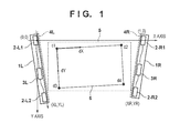
- FIG. 1 is an overall schematic diagram illustrating a coordinate input apparatus according to a first embodiment.
- FIG. 2 is a diagram illustrating operations carried out in a first detection mode of an operation control circuit according to the first embodiment.
- FIG. 3 is a flowchart illustrating an initial setting process according to the first embodiment.
- FIGS. 4A to 4E are diagrams illustrating detection signal waveforms according to the first embodiment.
- FIG. 5 is a diagram illustrating coordinate calculation carried out by sensor units according to the first embodiment.
- FIG. 6 is a diagram illustrating a second coordinate system according to the first embodiment.
- FIG. 7 is a diagram illustrating the calculation of conversion parameters for a coordinate system according to the first embodiment.
- FIGS. 8A and 8B are flowcharts illustrating normal operations and a calibration process according to the first embodiment.
- FIGS. 9A and 9B are diagrams illustrating coordinate calculation according to the first embodiment.
- FIGS. 10A to 10E are diagrams illustrating coordinate calculation according to the first embodiment.
- FIG. 11 is a diagram illustrating coordinate calculation according to the first embodiment.
- FIG. 1 The overall configuration of a coordinate input apparatus according to a first embodiment will be described using FIG. 1 .
- 1 L indicates a sensor bar serving as a housing that includes sensor units 2 -L 1 and 2 -L 2 (a first sensor unit and a second sensor unit), which serve as at least two angle detection sensor units.
- 1 R indicates a sensor bar serving as a housing that includes sensor units 2 -R 1 and 2 -R 2 (a third sensor unit and a fourth sensor unit).
- an image is projected and displayed on a display surface such as a planar whiteboard or the like using a display device such as a front projector or the like.
- a region where the image displayed is indicated as a display area 6 , and this is set to be within a range of a coordinate-input effective area 5 .
- the display surface is not limited to a whiteboard, and may be a wall surface or the like as well.
- the sensor bars 1 L and 1 R (referred to collectively as sensor bars 1 ) are installed on outer sides of the display area 6 by a user.
- the sensor bars 1 contain magnets, for example, and can therefore be attached to the whiteboard.
- Retroreflective portions 4 L and 4 R are, as illustrated in FIG. 1 , mounted on side surfaces on the sensor bars 1 L and 1 R, respectively.
- the configuration is such that the retroreflective portions 4 L and 4 R are capable of recursively reflecting infrared light projected by the sensor units in the sensor bar 1 L or 1 R provided on opposing sides, respectively.
- the sensor units 2 -L 1 and 2 -L 2 are provided in the sensor bar 1 L, and the sensor units 2 -R 1 and 2 -R 2 are provided in the sensor bar 1 R.
- An operation control circuit 3 L provided in the sensor bar 1 L controls the sensor units 2 -L 1 and 2 -L 2 , and along with processing output results thereof, controls an operation control circuit 3 R provided in the sensor bar 1 R.
- the operation control circuit 3 R of the sensor bar 1 R controls the sensor units 2 -R 1 and 2 -R 2 , processes output results thereof, and sends those results to the operation control circuit 3 L of the sensor bar 1 L.
- the operation control circuit 3 L of the sensor bar 1 L then processes the output results from the four sensor units 2 -L 1 , 2 -L 2 , 2 -R 1 , and 2 -R 2 , calculates a specified position (touch position), and outputs a result thereof to an external device such as a personal computer or the like.
- the sensor units 2 -L 1 , 2 -L 2 , 2 -R 1 , and 2 -R 2 each includes a light projector and a light receptor.
- Each light projector is constituted of an optical system, including an infrared LED, a light projecting lens, and so on, that projects light toward a coordinate input surface surrounded by the four sensor units.
- Each light receptor is constituted of an optical system, including a line CCD, a light receiving lens, and so on, that receives incoming light.
- the internal structures and so on of the light projectors and the light receptors are described in detail in, for example, Japanese Patent Laid-Open No. 2014-48960, and thus detailed descriptions thereof will not be given here.
- operation control circuit 3 L of the sensor bar 1 L and the operation control circuit 3 R of the sensor bar 1 R illustrated in FIG. 1 are configured so as to have, for example, functions for communicating wirelessly or the like with each other and use those communication functions to exchange data (a wireless connection), the configuration is not limited thereto.
- the communication may be carried out using wired communication functions as well.
- FIG. 2 is a block diagram illustrating the operation control circuits 3 . Aside from the specifications of their interfaces to the exterior, the operation control circuit 3 L of the sensor bar 1 L and the operation control circuit 3 R of the sensor bar 1 R according to the first embodiment have the same circuit configurations, and carry out control of and operations for the corresponding sensor units 2 connected thereto. FIG. 2 particularly illustrates the configuration of the operation control circuit 3 L of the sensor bar 1 L.
- CCD control signals for the line CCDs of the sensor units 2 -L 1 and 2 -L 2 are outputted from a CPU 61 configured as a single-chip microcomputer or the like, and control the shutter timings, data output, and so on of the line CCDs.
- a CCD clock is sent to the sensor units 2 -L 1 and 2 -L 2 from a clock generating circuit CLK 62 , and is also input into the CPU 61 in order to carry out various types of control in synchronization with the line CCDs.
- LED driving signals for driving infrared LEDs 31 of the sensor units 2 -L 1 and 2 -L 2 are supplied from the CPU 61 .
- Detection signals from the line CCDs of the sensor units 2 -L 1 and 2 -L 2 are input into an A/D converter 63 and converted to digital values under the control of the CPU 61 .
- the digital values obtained from the conversion are stored in a memory 64 and used in angle calculations.
- a geometric specified position is calculated from the calculated angle information and is output to an information processing apparatus such as an external PC or the like through an interface 68 (a USB interface, for example).
- the operation control circuit 3 in each sensor bar 1 controls two sensor units 2 .
- the CPU 61 synchronizes the circuits by sending control signals to the operation control circuit 3 R of the sensor bar 1 R through a serial communication unit 67 . Necessary data is then obtained from the operation control circuit 3 R.
- the operation control circuit 3 L is the master and the operation control circuit 3 R is the slave.
- each operation control circuit can serve as the master or the slave, the master/slave relationship can be switched by inputting a switching signal to a port of the CPU 61 using a switching unit such as a dip switch or the like (not shown).
- the control signal is sent to the operation control circuit 3 R of the slave through the serial communication unit 67 from the operation control circuit 3 L of the sensor bar 1 L serving as the master.
- the angle information obtained by the sensor units 2 -R 1 and 2 -R 2 is calculated and sent to the operation control circuit 3 L on the master side through the serial communication unit 67 .
- the interface 68 is provided in the operation control circuit 3 L on the master side.
- 66 indicates an infrared light receptor for when a dedicated stylus (not shown) that emits infrared is used as a pointing device.
- 65 indicates a sub CPU for decoding signals from the dedicated stylus.
- the dedicated stylus has a switch that detects when a tip of the stylus has been pressed against an input surface, various switches on a side area of the stylus housing, and so on. Operating states of the dedicated stylus can be detected by sending states of the switches, stylus identification information, and so on using an infrared light emitting unit provided in the dedicated stylus.
- FIG. 3 is a flowchart illustrating an initial setting process from when power is turned on. Note that this initial setting process is realized by the CPU 61 reading out programs stored in the memory 64 and executing those programs upon the user turning the power of the coordinate input apparatus on.
- the sensor bars 1 are attached to a wall surface by an operator in order to form the rectangular coordinate-input effective area 5 including the entirety of the display area 6 , which is a projected image.
- the sensor bars 1 contain magnets, for example, and can therefore be attached to the wall surface.
- the CPU 61 starts the initial setting process, making various types of initialization operations for the coordinate input apparatus such as setting input and output ports, setting a timer, and so on, and also initializes the line CCD by eliminating excess charges remaining in photoelectric conversion elements (S 102 ).
- This coordinate input apparatus has a first coordinate detection mode that detects an instruction (a touch) made by a pointing device such as a finger in the coordinate-input effective area 5 , and a second coordinate detection mode for detecting an installation position of the coordinate input apparatus.
- the sensor units 2 -L 1 and 2 -L 2 of the sensor bar 1 L directly detect infrared light of the infrared LEDs, emitted from the sensor units 2 -R 1 and 2 -R 2 of the opposing sensor bar 1 R.
- the sensor units 2 -R 1 and 2 -R 2 of the sensor bar 1 R directly detect infrared light of the infrared LEDs, emitted from the sensor units 2 -L 1 and 2 -L 2 of the opposing sensor bar 1 L.
- the CPU 61 carries out operation settings for setting predetermined initial values such as an open shutter time for the line CCDs, a lighting time for the infrared LEDs, and so on, or a driving current of the infrared LEDs or the like (S 103 ).
- the purpose of the operation settings is to derive relative positional relationship between the four sensor units 2 in a state of operations where light is directly received from the opposing sensor units 2 (the second detection mode).
- the CPU 61 captures an output signal from the line CCD (S 104 ). The CPU 61 then determines whether or not light has been successfully detected by checking the positions of the sensor units (S 105 ).
- FIG. 4E A signal waveform output from the line CCD at this time is illustrated in FIG. 4E .
- a state in which two peaks are formed can be called a normal state.
- the sensor units 2 in opposing positions are not positioned in a visual field range of the light receptors of the sensor units 2 .
- the CPU 61 checks a waveform level of the detection signal (S 107 ).
- the process returns to S 103 , where settings such as reducing an exposure time are made again.
- the detection signal waveform will have a lower optical intensity.
- at least part of the detection signal waveform is less than or equal to the predetermined threshold (YES in S 107 )
- it is determined that that signal level is appropriate.
- the above operations are executed for each sensor unit (four, in the first embodiment), and when all of the signals have been optimized, the CPU 61 executes a positional relationship calculation process that calculates the relative positional relationship between the sensor units 2 (S 108 ).
- FIG. 5 An example of a method for calculating the position of each sensor unit, carried out in S 108 , will be described using FIG. 5 .
- ⁇ 1 to ⁇ 4 indicated in FIG. 5 are calculated on the basis of the waveforms of the detection signals obtained by the sensor units.
- pixel numbers corresponding to the two peaks are converted into angle values.
- Table lookup, a conversion formula, or the like is used to convert from pixel numbers into angle values.
- a conversion formula can ensure accuracy by using a higher-order polynomial expression, for example, but the order and the like should be determined in light of computational capabilities, accuracy specifications, and so on.
- a case where a fifth-order polynomial expression is used will be described as an example.
- a relationship between the pixel numbers and angles of the sensor units is measured when assembling the apparatus or the like.
- Coefficient data for converting the pixel numbers into angle values using fifth-order polynomial approximation is then calculated from the measurement results.
- the coefficient data is then stored in the memory 64 , which is a non-volatile memory or the like, within the apparatus. Six pieces of coefficient data are necessary in the case where a fifth-order polynomial expression is used, and thus that coefficient data may be stored in the memory 64 when the apparatus is shipped or the like.
- the pixel numbers corresponding to the two respective peaks are converted into angle values through Formula (1). Differences between the two angle values resulting from the conversion are taken as ⁇ 1 to ⁇ 4 , respectively. For example, a difference between the two angle values calculated from the detection waveform of the sensor unit 2 -L 1 is ⁇ 1 .
- a direction connecting the origin to the sensor unit 2 -R 1 by a straight line is taken as an X axis, and the direction perpendicular to the X axis is taken as a Y axis.
- a coordinate value of the sensor unit 2 -R 1 is set to (1,0), and a coordinate system based on the relative positional relationship between the sensor units is set.
- the coordinate system based on the combination of the sensor unit 2 -R 1 and the sensor unit 2 -L 1 is taken as a first coordinate system (a coordinate system defined by the X axis and the Y axis in FIG. 5 ).
- This coordinate input apparatus is designed so that an angle formed between an optical axis of the sensor unit 2 -L 1 and a straight line connecting the center of the optical axis of the sensor unit 2 -L 1 and the center of an optical axis of the sensor unit 2 -L 2 is a predetermined angle ( ⁇ /2[rad]), as illustrated in FIG. 5 .
- This value is stored as reference angle information in the memory 64 (a reference angle information storage unit).
- the reference angle information is stored, for example, through an operation for measuring the reference angle and storing the information in the memory 64 , such as when the apparatus is assembled at a factory or the like. Pixel numbers in the optical axis directions of the respective sensor units are measured in advance and stored in the memory 64 .
- the coordinates of the sensor unit 2 -L 2 and the sensor unit 2 -R 2 are calculated using ⁇ 1 to ⁇ 5 .
- the coordinates of the sensor unit 2 -L 2 are represented by (XL,YL) and the coordinates of the sensor unit 2 -R 2 are represented by (XR,YR)
- the following formulae hold true in the case of FIG. 5 .
- YL XL *tan( ⁇ 1+ ⁇ 5)
- YL (1 ⁇ XL )*tan ⁇ 3
- YR XR *tan ⁇ 1 (5)
- YR ⁇ YL ( XR ⁇ XL )*tan( ⁇ 2 ⁇ 3) (6)
- XL is calculated using Formula (7). Then, YL is calculated using the calculated XL and Formula (3). Next, XR is calculated using the calculated XL, YL, and Formula (8). Then, YR is calculated using the calculated XR and Formula (5).
- the coordinates (XL,YL) of the sensor unit 2 -L 2 and the coordinates (XR,YR) of the sensor unit 2 -R 2 are thus calculated through the stated procedure.
- the method of calculating the coordinate values (positions) of the sensor units described here is merely an example, and the calculations may of course be carried out using other formulae, procedures, and so on.
- a second coordinate system different from the XY coordinate system illustrated in FIG. 5 , is used in order to improve the accuracy of the calculated coordinates.
- the second coordinate system takes the sensor unit 2 -L 2 as an origin, the coordinate values of the sensor unit 2 -R 2 as (1,0), and the direction perpendicular to the X axis as the Y axis.
- the CPU 61 calculates conversion parameters necessary for the coordinate conversion (S 109 ). Specifically, as illustrated in FIG. 7 , a distance Lb between the sensor unit 2 -L 2 and the sensor unit 2 -R 2 in the first coordinate system, and an angle ⁇ b formed between the X axis direction and a line connecting the sensor unit 2 -L 2 and the sensor unit 2 -R 2 , are calculated as the conversion parameters.
- Lb SQRT(( XR ⁇ XL ) 2 +( YR ⁇ YL ) 2 ) (9)
- ⁇ b ARCTAN(( YR ⁇ YL )/( XR ⁇ XL )) (10)
- SQRT( ) represents a function for finding a square root
- ARCTAN( ) represents an arc tangent function.
- the CPU 61 then saves Lb and ⁇ b, which are the conversion parameters, in the memory 64 (S 110 ).
- the CPU 61 optimizes signal levels obtained when infrared light projected by the sensor units 2 is retroreflected by the retroreflective portions 4 provided on the opposing sensor bars 1 and that light is detected by the sensor bars 1 ′ own light receptors 40 .
- the positioning of the sensor bars 1 is not absolute, and optimizing the detection levels in accordance with the positioning is carried out in order to obtain stable signals.
- the items to be set including the open shutter time of the line CCDs, the lighting time of the infrared LEDs, and so on, or the driving current of the infrared LEDs, are set through the operation settings carried out in the first detection mode (S 111 ). Assuming the operation settings have been set so that the maximum amount of light is obtained for the first time (S 111 ), the CPU 61 captures the output signals from the line CCDs at that time (S 112 ).
- the captured output signals correspond to illumination data, and have waveforms such as those indicated in FIG. 4B .
- Level A indicates that the amount of detected light is at a maximum level
- a level B is a level where no light is being detected. If the light is too intense, the light will exceed the dynamic range of the line CCD and the output will saturate, and it will become difficult to calculate the angles accurately. Accordingly, the CPU 61 checks the waveform levels of the detection signals (S 113 ). If it is determined as a result of the check that the waveforms of the detection signal are unsuitable (NO in S 113 ), the process returns to S 111 , where settings are carried out again so that the waveforms (waveform levels) of the detection signals decrease.
- the retroreflected light is detected, and thus settings are made to significantly increase the amount of light projected as compared to when the light projected by the sensor units 2 is detected directly by the light receptors 40 in the processes of S 103 to S 107 (in other words, in the second detection mode).
- the CPU 61 A/D-converts the outputs of the line CCDs using the A/D converter 63 in a state where the light projectors of the sensor units are not emitting light.
- the CPU 61 then stores those values as Base_Data[N] in the memory 64 (S 114 ).
- Base_Data[N] This is data containing variation due to bias in the line CCDs and the like, and is data near the level B indicated in FIG. 4A .
- [N] indicates the CCD pixel number of the line CCD, and a pixel number corresponding to an active input range is used.
- the CPU 61 obtains a light amount distribution in a state where light is projected from the light projectors of the sensor units. This is data indicated by the solid line in FIG. 4B , and the CPU 61 stores this data as Ref_Data[N] in the memory 64 (S 115 ).
- the CPU 61 executes the initial setting process illustrated in FIG. 3 (S 101 ). Then, as normal capturing operations (the first detection mode), the CPU 61 detects signals obtained when infrared light projected by the sensor units 2 is retroreflected by the retroreflective portions 4 provided on the opposing sensor bars 1 and that light is detected by the sensor bars 1 ′ own light receptors 40 (S 201 ). The data at that time is Norm_data[N], and assuming that a touch operation is made on the input surface in the coordinate-input effective area 5 and the optical path is blocked, the sensor unit will be unable to detect an optical signal around a pixel number Nc, as indicated in FIG. 4C , for example.
- the CPU 61 determines whether or not such a light-shielded portion has been produced by any of the sensor units 2 , or in other words, whether or not an input has been made (S 202 ). In the case where it is determined that no input has been made (NO in S 202 ), the process returns to S 201 , where the sampling is repeated. On the other hand, in the case where it is determined that an input has been made (YES in S 202 ), the CPU 61 selects the sensor unit for which a light-shielded portion has been produced in the output signal (S 203 ). Using the selected sensor unit, the CPU 61 calculates the respective directions (angles) in which the light-shielded portion is produced (S 204 ). Here, the sample data obtained in a state where that light projector is emitting light is defined as the Norm_Data[N].
- the CPU 61 can calculate the direction of the touch position, or to rephrase, the angle, using the signals indicated in FIGS. 4A to 4C .
- the CPU 61 first determines whether or not an input has been made using a pointing device, and whether or not a light-shielded portion is present, using the Base_Data[N] and the Ref_Data[N] stored in the memory 64 . First, to specify the light-shielded portion, an amount of change in the data at each pixel is calculated and compared with a pre-set threshold Vtha.
- Norm_Data0 [N ] Norm_Data[ N ] ⁇ Ref_Data[ N] (11)
- Norm_Data 0 [N] represents an absolute amount of change in the light amount at each pixel; by comparing with the threshold, error caused by noise or the like is prevented and a predetermined amount of definite change is detected. Then, in the case where data exceeding the threshold has occurred for greater than or equal to a predetermined number of consecutive pixels, for example, it is determined that a touch operation has been made. This process is simply a comparison that finds a difference, and thus the computation can be made in a short time, and whether or not an input has been made can therefore be determined quickly.
- Norm_Data R[N ] Norm_Data0 [N ]/(Base_Data[ N ] ⁇ Ref_Data[ N ]) (12)
- a different threshold Vthr is applied to this pixel data (light amount distribution). Then, on the basis of the pixel numbers at a rise point and a fall point in a light amount variation area corresponding to the light-shielded portion in the light amount distribution, which correspond to points where that threshold Vthr is crossed, the angle is calculated by taking the center between the two pixel numbers as a pixel corresponding to the input made using the pointing device.
- FIG. 4D illustrates an example of calculating the ratio of change in the pixel data. It is assumed here that when detecting on the basis of the threshold Vthr, the rise area of the light-shielded portion reaches a level Ls at an Ns-th pixel and exceeds the threshold Vthr. Furthermore, it is assumed that the level drops to a level Lt at an Nt-th pixel and drops below the threshold Vthr.
- a pixel number Np of the line CCD that is to be output may be calculated as a median value of the pixel numbers of the rise area and the fall area as indicated in Formula (13), but doing so means that the pixel interval of the line CCD will be the resolution of the output pixel number.
- Np (( Ns ⁇ 1)+ Nt )/2 (13)
- an estimated pixel number where the threshold Vthr will be crossed is calculated using the data levels of the respective pixels and the data levels of the adjacent pixels previous thereto.
- Nsv Ns ⁇ 1+( Vthr ⁇ Ls ⁇ 1)/( Ls ⁇ Ls ⁇ 1)
- Ntv Nt ⁇ 1+( Vthr ⁇ Lt ⁇ 1)/( Lt ⁇ Lt ⁇ 1)
- a higher-resolution detection can be realized by calculating the virtual estimated pixel numbers where the threshold Vthr at a predetermined level is crossed from pixel numbers of the pixels whose data levels exceed the threshold Vthr and the pixel numbers adjacent thereto, and from the data levels thereof, in this manner.
- FIGS. 9A and 9B an example of expressing a position on the screen when a light-shielded portion (a shadow) is produced by a touch will be described with reference to FIGS. 9A and 9B .
- an angle of the light-shielded portion detected by the sensor unit 2 -L 1 is represented by ⁇ 6 and an angle of the light-shielded portion detected by the sensor unit 2 -R 1 is represented by ⁇ 7 .
- FIG. 9B an angle of the light-shielded portion detected by the sensor unit 2 -L 2 is represented by ⁇ 8 and an angle of the light-shielded portion detected by the sensor unit 2 -R 2 is represented by ⁇ 9 .
- ⁇ 8 and ⁇ 9 are angles obtained when a direction parallel to the X axis and the respective sensor units (a direction indicated by the dotted line) is taken as a reference.
- the direction parallel to the sensor unit 2 -L 2 and the X axis is calculated as a direction (angle) obtained by rotating the direction when the sensor unit 2 -R 1 is detected by the sensor unit 2 -L 2 by ⁇ 3 , when the relative coordinates of each sensor unit are calculated, as indicated in FIG. 5 .
- the same applies to the sensor unit 2 -R 2 where the direction parallel to the X axis is calculated as a direction (angle) obtained by rotating the direction when the sensor unit 2 -L 1 is detected by the sensor unit 2 -R 2 by ⁇ 1 .
- the CPU 61 calculates the coordinates of the specified position in the relative coordinate system on the basis of these calculated angles (S 205 ). The process of calculating the coordinates of the specified position is carried out as described hereinafter.
- FIGS. 10A to 10E are diagrams illustrating positional relationships with screen coordinates.
- Visual field ranges of the sensor unit 2 -L 1 and the sensor unit 2 -L 1 of the sensor bar 1 L are ranges between the two arrows indicated for each of those sensor units. Accordingly, based on the visual field ranges of the sensor unit 2 -L 1 and the sensor unit 2 -L 2 , a specified position P can only be calculated in the case where the specified position P is within the range indicated by the hatching in FIG. 10A . In the case where the specified position is not within that range, the combination of the sensors units used in the calculation is changed as indicated in FIGS.
- the sensor units needed to calculate the coordinates are selected on the basis of whether or not there is a light-shielded direction detected by the respective sensor units 2 and those light-shielding directions, and the coordinates of the specified position are calculated.
- the specified position P can be calculated by combining the sensor units in the states indicated in FIG. 10A or FIG. 10B .
- the visual field range of the sensor unit 2 -L 2 and the visual field range of the sensor unit 2 -R 1 are set so as to overlap in the direction of an opposing corner line in the coordinate-input effective area 5 .
- the coordinates can be calculated according to a plurality of sensor unit combinations. In this case, an average value of the coordinate values calculated through the two combinations may be output as final coordinates.
- a light-shielded portion in the area indicated in FIG. 10A is detected by the sensor unit 2 -L 1 and the sensor unit 2 -L 2 .
- x is calculated from Formula (21), and furthermore, y is calculated from the calculated x and Formula (17).
- x is calculated from Formula (22), and furthermore, y is calculated from the calculated x and Formula (17).
- x is calculated from Formula (23), and furthermore, y is calculated from the calculated x and Formula (18).
- x is calculated from Formula (24), and furthermore, y is calculated from the calculated x and Formula (19).
- the direction parallel to the X axis for the sensor unit 2 -L 2 is calculated as a direction (angle) obtained by rotating the direction when the sensor unit 2 -R 1 is detected by the sensor unit 2 -L 2 by ⁇ 3 , as indicated in FIG. 5 .
- the same applies to the sensor unit 2 -R 2 where the direction parallel to the X axis is calculated as a direction (angle) obtained by rotating the direction when the sensor unit 2 -L 1 is detected by the sensor unit 2 -R 2 by ⁇ 1 .
- error arises due to a variety of factors in an actual coordinate input apparatus.
- table lookup or polynomial approximation is used for the conversion, and error also arises at that time.
- the aforementioned reference angle information is measured when, for example, the apparatus is assembled at a factory or the like, and measurement error occurs at that time. Further still, if, for example, attachment positions in sensor unit, optical systems therein, and so on shift over time, further error will occur.
- the calculated angle values will contain error due to these various factors.
- ⁇ 1 or ⁇ 3 contain error due to error in the angular characteristics of the sensor units, the direction that is expected to be parallel to the X axis (the direction indicated by the dotted line in FIG. 5 ) will become shifted.
- ⁇ 8 and ⁇ 9 are calculated using the direction parallel to the X axis as a reference, and thus angular error in ⁇ 1 and ⁇ 3 will also be added directly to ⁇ 8 and ⁇ 9 as error.
- x is calculated from Formula (27), and y is then calculated from the calculated x and Formula (25).
- the calculated coordinate values in the second coordinate system are converted into coordinate values in the first coordinate system.
- the coordinate conversion can be carried out as indicated in the following formulae, using the conversion parameters calculated in S 109 (the distance Lb and the angle of rotation ⁇ b).
- this coordinate value conversion includes at least one of coordinate value rotation, enlargement of the coordinate values in a predetermined direction, and parallel movement (offset) of the coordinate values.
- the conversion parameter is an angle of rotation in that rotation process.
- the conversion parameter is an enlargement rate used in that enlargement process. Furthermore, in the case where the coordinate values are converted through parallel movement (offset) of the coordinate values, the conversion parameter is an offset amount used in that offset process.
- ⁇ 10 and ⁇ 11 in Formula (27) are angles measured using, as a reference, directions in which light from the opposing sensor units is detected in the aforementioned process for detecting the installation position of the apparatus. As indicated by Formula (24), no angular error is added to ⁇ 1 and ⁇ 3 , and thus the angle error can be suppressed to a low amount.
- the CPU 61 calculates the relative coordinate values (x,y) of the specified position in the relative coordinate system for the specified position, and converts the calculated relative coordinate values of the specified position into coordinate values in a display coordinate system (S 206 ).
- Projection conversion or the like can be given as a method for converting the calculated relative coordinate values of the specified position into the coordinate values in the display coordinate system. Because this is a typical coordinate conversion method, detailed descriptions thereof will not be given here. However, a process for obtaining parameters necessary for this coordinate conversion will be described later.
- the CPU 61 then outputs (sends) the coordinate values resulting from the conversion to an external device such as a personal computer or the like (S 207 ).
- a touch-down signal/touch-up signal indicating whether or not the input screen is being touched, may also be output.
- the optical path is blocked 100% when the touch surface is touched, but small amounts of light progressively pass as the pointing device is lifted from the touch state. Accordingly, calculating the degree to which the light is blocked makes it possible to determine, by setting a threshold, whether the state is a touch state, or a state in which the surface is not being touched but the optical path is blocked (that is, a state in which angles can be calculated and the position thereof can also be calculated even in such a state).
- the display coordinate system is a linear, two-dimensional coordinate system that takes d 1 as an origin and has a dX axis and a dY axis.
- Information indicating a positional relationship between the relative coordinate system and the display coordinate system is necessary in order to set the parameters for the coordinate conversion.
- a process called calibration is carried out in order to obtain the necessary information.
- a dedicated application is installed in a personal computer (PC) that is carrying out the display control.
- PC personal computer
- an indicator such as a plus-shaped cross or the like is displayed in the display screen, and the user is then prompted to touch the position of that indicator.
- Coordinate system conversion is then carried out so that coordinate values in the relative coordinate system obtained by repeating that operation a predetermined number of times in different positions match coordinate values in the display coordinate system at positions where the indicator is displayed.
- the calibration is realized by touching the four corners of the display screen, rather than displaying an indicator using application software and having the user touch the position thereof.
- Employing such configuration provides a useful effect in that the apparatus can be used immediately by connecting to a nearby PC, without installing any special software.
- This calibration mode is transited to by, for example, manipulating a switching unit such as a switch or the like provided in the coordinate input apparatus.
- a flowchart for this calibration mode is indicated in FIG. 8B , and details of the processing will be described next.
- the calibration mode is executed immediately after the sensor bars 1 have been installed, or in the case where the position of the display has shifted for some reason after the installation has already been completed.
- the CPU 61 carries out the initial setting process (S 101 ). This is done assuming a case where the positions of the sensor bars have shifted during use, so as to optimize the optical output and correct for positional shifting in the sensors.
- S 201 and S 202 are carried out to allow the user to touch the four corners of the display area 6 , and the CPU 61 determines whether one of those positions has been touched.
- the CPU 61 calculates the necessary angle information.
- the CPU 61 then makes a notification that the data has been successfully obtained (S 301 ). This notification is carried out by, for example, outputting a beep sound indicating that the obtainment is complete.
- the CPU 61 determines whether or not the information has been obtained for all four corners of the display area 6 (S 302 ). The process returns to S 201 in the case where the obtainment is not complete (NO in S 302 ). However, in the case where the obtainment is complete (YES in S 302 ), the CPU 61 calculates the parameters for converting from the relative coordinate system to the display coordinate system (S 303 ). Coordinate values at four corresponding locations are obtained from both the relative coordinate system and the display coordinate system, and thus the coordinate conversion can be carried out through a method such as projection conversion, and the necessary parameters (values of elements in a transformation matrix or the like) can be calculated.
- the calibration mode is completed through the aforementioned processing, and the operations then return to normal operations (that is, the process advances to S 201 in FIG. 8A ).
- the parameters calculated in the calibration mode are then used in the coordinate conversion carried out in S 206 .
- Positions in the display screen relative to the installation position of the apparatus are associated through the aforementioned calibration processing, and thus at this time, it is possible to examine whether or not the display screen is in the effective range of the apparatus. For example, in the case where it is determined that the display screen is outside of the effective range as a result of examining the effective range, a process may be carried out that prompts the user to readjust the display screen by emitting a beep sound, audio, or the like, for example.
- driver software is run in advance on a connected PC for carrying out screen adjustment.
- information indicating an amount by which the display screen is shifted from the effective range is sent to the driver software.
- the driver software can receive this information and automatically adjust the display screen.
- the accuracy of coordinates calculated for a touch position can be improved.
- the first embodiment describes a configuration in which touch coordinates are calculated by varying the combinations of sensor units used in the calculation for the areas indicated in FIGS. 10A to 10D .
- error tends to exceed a predetermined value particularly in areas near the bottom side of the coordinate-input effective area 5 , and thus the accuracy of the coordinates calculated for the touch position is improved by calculating the coordinates in the area indicated in FIG. 10D using a different method.
- a second embodiment describes another example of a coordinate calculation process carried out for the area indicated in FIG. 10D , executed in S 205 of FIG. 8A .
- the configuration of the apparatus and so on is the same as in the first embodiment, and thus descriptions thereof will be omitted.
- coordinates are calculated in the first coordinate system for the area indicated in FIG. 10D .
- x is calculated from Formula (24), and furthermore, y is calculated from the calculated x and Formula (19).
- the calculated coordinate values are represented by (x1,y1).
- Y 0 MIN( YL,YR )*0.6 (30)
- Y 1 MIN( YL,YR )*0.8 (31)
- MIN( ) represents a function that returns the minimum value among the arguments.
- the positions of Y0 and Y1 are as indicated in FIG. 11 , for example.
- YR ⁇ YL and thus Y0 and Y1 are values equivalent to 0.6 ⁇ and 0.8 ⁇ the value of YR, respectively.
- the values of 0.6, 0.8, and so on are set in advance as fixed values, in consideration of the range in which the average calculation is carried out.
- (x3,y3) are calculated as follows, depending on the magnitude relationship between y2, and Y0 and Y1.
- a weighted average of both may be taken in the area where Y0 ⁇ y2 ⁇ Y1, in order to connect the borders between areas in a smooth manner.
- the process becomes one in which a single border is set and one of (x1,y1) and (x2,y2) is selected; as such, Formulae (34) and (35) are not used, which makes it possible to simplify the calculations.
- the processing is not limited to y2; for example, y0 may be used, a value obtained by averaging y0 and y2 may be used, and so on.
- different processes may be carried out in the x direction by further using the value of x. The way in which the areas are divided may be determined in consideration of the tendency of errors to arise.
- the coordinates are calculated in accordance with a distance of the touch position from the bottom end of the coordinate-input effective area 5 , by examining the calculated y coordinate.
- the accuracy of the coordinates in areas near the lower side, where the coordinate calculation error in particular is greater than in other areas, can be improved.
- the sensor units include infrared LEDs as light projectors and line CCD sensors as light receptors in the aforementioned embodiments, the invention is not limited thereto.
- the aforementioned embodiments can also be applied in a system that uses cameras, which are image capturing devices.
- the sensor units 2 -L 1 , 2 -L 2 , 2 -R 1 , and 2 -R 2 include cameras. Each camera captures an image in the direction of the coordinate-input effective area 5 , and angles at which the other cameras are positioned are detected through an image recognition process such as matching or the like. Using the mutually-detected angles, the position in which the coordinate input apparatus is installed can be detected in the same manner as in the first embodiment.
- a method that detects input from a finger or the like using image recognition processing a method that uses a stylus, and so on can be given as methods for detecting touches using cameras.
- a method that uses a stylus for example, an LED is provided in the tip of the stylus, the LED is caused to emit light during a touch, and the angle of the input is detected by the camera detecting that emitted light. The coordinate values of that touch position can then be calculated on the basis of the detected angles.
- Embodiments of the present invention can also be realized by a computer of a system or apparatus that reads out and executes computer executable instructions (e. g., one or more programs) recorded on a storage medium (which may also be referred to more fully as a ‘non-transitory computer-readable storage medium’) to perform the functions of one or more of the above-described embodiments and/or that includes one or more circuits (e.
- the computer may comprise one or more processors (e. g., central processing unit (CPU), micro processing unit (MPU)) and may include a network of separate computers or separate processors to read out and execute the computer executable instructions.
- the computer executable instructions may be provided to the computer, for example, from a network or the storage medium.
- the storage medium may include, for example, one or more of a hard disk, a random-access memory (RAM), a read only memory (ROM), a storage of distributed computing systems, an optical disk (such as a compact disc (CD), digital versatile disc (DVD), or Blu-ray Disc (BD)TM), a flash memory device, a memory card, and the like.
- RAM random-access memory
- ROM read only memory
- BD Blu-ray Disc
Landscapes
- Engineering & Computer Science (AREA)
- General Engineering & Computer Science (AREA)
- Theoretical Computer Science (AREA)
- Human Computer Interaction (AREA)
- Physics & Mathematics (AREA)
- General Physics & Mathematics (AREA)
- Position Input By Displaying (AREA)
Abstract
Description
θ=((((L5*Npr+L4)*Npr+L3)*Npr+L2)*Npr+L1)*Npr+L0 (1)
The pixel numbers corresponding to the two respective peaks are converted into angle values through Formula (1). Differences between the two angle values resulting from the conversion are taken as θ1 to θ4, respectively. For example, a difference between the two angle values calculated from the detection waveform of the sensor unit 2-L1 is θ1.
θ5=π/2−(θj−θk) (2)
YL=XL*tan(θ1+θ5) (3)
YL=(1−XL)*tan θ3 (4)
YR=XR*tan θ1 (5)
YR−YL=(XR−XL)*tan(θ2−θ3) (6)
XL=tan θ3/(tan(θ1+θ5)+tan θ3) (7)
XR=(YL−XL*tan(θ2−θ3))/(tan θ1−tan(θ2−θ3)) (8)
Lb=SQRT((XR−XL)2+(YR−YL)2) (9)
θb=ARCTAN((YR−YL)/(XR−XL)) (10)
Norm_Data0[N]=Norm_Data[N]−Ref_Data[N] (11)
Norm_DataR[N]=Norm_Data0[N]/(Base_Data[N]−Ref_Data[N]) (12)
Np=((Ns−1)+Nt)/2 (13)
Nsv=Ns−1+(Vthr−Ls−1)/(Ls−Ls−1) (14)
Ntv=Nt−1+(Vthr−Lt−1)/(Lt−Lt−1) (15)
Through these formulae, estimated pixel numbers based on the output levels, or in other words, pixel numbers that are finer than the pixel numbers of the line CCD, can be obtained. An estimated center pixel Npv of the estimated pixel numbers Nsv and Ntv is then determined through Formula (16).
Npv=(Nsv+Ntv)/2 (16)
y=x*tan θ6 (17)
y=(1−x)*tan θ7 (18)
YL−y=(x−XL)*tan θ8 (19)
YR−y=(XR−x)*tan θ9 (20)
x=(YL+XL*tan θ8)/(tan θ6+tan θ8) (21)
x=tan θ7/(tan θ6+tan θ7) (22)
x=(tan θ7+XR*tan θ9−YR)/(tan θ7+tan θ9) (23)
x=(XL*tan θ8+XR*tan θ9+YL−YR)/(tan θ8+tan θ9) (24)
y=−x*tan θ10 (25)
y=−(1−x)*tan θ11 (26)
x=tan θ11/(tan θ10+tan θ11) (27)
x′=(x*cos θb−y*sin θb)*Lb+XL (28)
y′=(x*sin θb−y*cos θb)*Lb+YL (29)
Y0=MIN(YL,YR)*0.6 (30)
Y1=MIN(YL,YR)*0.8 (31)
x3=x1 (32)
y3=y1 (33)
x3=((y1−Y0)*x2+(Y1−y1)*x1)/(Y1−Y0)) (34)
y3=((y1−Y0)*y2+(Y1−y1)*y1)/(Y1−Y0)) (35)
x3=x2 (36)
y3=y2 (37)
Claims (12)
Applications Claiming Priority (2)
| Application Number | Priority Date | Filing Date | Title |
|---|---|---|---|
| JP2015-021490 | 2015-02-05 | ||
| JP2015021490A JP2016143400A (en) | 2015-02-05 | 2015-02-05 | Coordinate input device and control method thereof |
Publications (2)
| Publication Number | Publication Date |
|---|---|
| US20160231867A1 US20160231867A1 (en) | 2016-08-11 |
| US9958989B2 true US9958989B2 (en) | 2018-05-01 |
Family
ID=56565417
Family Applications (1)
| Application Number | Title | Priority Date | Filing Date |
|---|---|---|---|
| US15/012,952 Active 2036-06-04 US9958989B2 (en) | 2015-02-05 | 2016-02-02 | Coordinate input apparatus, control method thereof, and non-transitory computer-readable storage medium |
Country Status (2)
| Country | Link |
|---|---|
| US (1) | US9958989B2 (en) |
| JP (1) | JP2016143400A (en) |
Citations (9)
| Publication number | Priority date | Publication date | Assignee | Title |
|---|---|---|---|---|
| US5304988A (en) * | 1990-08-03 | 1994-04-19 | Canon Kabushiki Kaisha | Character processing method |
| US20040021645A1 (en) * | 2002-07-30 | 2004-02-05 | Canon Kabushiki Kaisha | Coordinate input apparatus, control method thereof, and program |
| JP2004272353A (en) | 2003-03-05 | 2004-09-30 | Canon Inc | Coordinate input device |
| US20080284987A1 (en) * | 2004-10-20 | 2008-11-20 | Sharp Kabushiki Kaisha | Image Projecting Method, Projector, and Computer Program Product |
| US20110210979A1 (en) * | 2010-02-26 | 2011-09-01 | Seiko Epson Corporation | Correction information calculator, image correction device, image display system, correction information calculation method |
| US20130234955A1 (en) * | 2012-03-08 | 2013-09-12 | Canon Kabushiki Kaisha | Coordinate input apparatus |
| US20130257814A1 (en) * | 2012-03-30 | 2013-10-03 | Canon Kabushiki Kaisha | Coordinate input apparatus |
| US20140062963A1 (en) | 2012-08-31 | 2014-03-06 | Canon Kabushiki Kaisha | Coordinate input apparatus, control method therefor, and computer-readable medium |
| US20150205437A1 (en) * | 2014-01-23 | 2015-07-23 | Kyocera Document Solutions Inc. | Electronic Device, Method, and Program for Supporting Touch Panel Operation |
-
2015
- 2015-02-05 JP JP2015021490A patent/JP2016143400A/en active Pending
-
2016
- 2016-02-02 US US15/012,952 patent/US9958989B2/en active Active
Patent Citations (10)
| Publication number | Priority date | Publication date | Assignee | Title |
|---|---|---|---|---|
| US5304988A (en) * | 1990-08-03 | 1994-04-19 | Canon Kabushiki Kaisha | Character processing method |
| US20040021645A1 (en) * | 2002-07-30 | 2004-02-05 | Canon Kabushiki Kaisha | Coordinate input apparatus, control method thereof, and program |
| JP2004272353A (en) | 2003-03-05 | 2004-09-30 | Canon Inc | Coordinate input device |
| US20080284987A1 (en) * | 2004-10-20 | 2008-11-20 | Sharp Kabushiki Kaisha | Image Projecting Method, Projector, and Computer Program Product |
| US20110210979A1 (en) * | 2010-02-26 | 2011-09-01 | Seiko Epson Corporation | Correction information calculator, image correction device, image display system, correction information calculation method |
| US20130234955A1 (en) * | 2012-03-08 | 2013-09-12 | Canon Kabushiki Kaisha | Coordinate input apparatus |
| US20130257814A1 (en) * | 2012-03-30 | 2013-10-03 | Canon Kabushiki Kaisha | Coordinate input apparatus |
| US20140062963A1 (en) | 2012-08-31 | 2014-03-06 | Canon Kabushiki Kaisha | Coordinate input apparatus, control method therefor, and computer-readable medium |
| JP2014048960A (en) | 2012-08-31 | 2014-03-17 | Canon Inc | Coordinate input device, method for controlling the same and program |
| US20150205437A1 (en) * | 2014-01-23 | 2015-07-23 | Kyocera Document Solutions Inc. | Electronic Device, Method, and Program for Supporting Touch Panel Operation |
Also Published As
| Publication number | Publication date |
|---|---|
| JP2016143400A (en) | 2016-08-08 |
| US20160231867A1 (en) | 2016-08-11 |
Similar Documents
| Publication | Publication Date | Title |
|---|---|---|
| US9335865B2 (en) | Coordinate input apparatus, control method therefor, and computer-readable medium | |
| JP5973849B2 (en) | Coordinate input device and sensor bar used for coordinate input device | |
| CN102841710B (en) | sensing method and device | |
| US8941622B2 (en) | Coordinate input apparatus | |
| US8791925B2 (en) | Coordinate input apparatus, control method therefor and program | |
| US9377897B2 (en) | Control of coordinate input apparatus based on light distribution and moving amounts of sensor units | |
| TW201617790A (en) | Corner generation in a projector display area | |
| US9958989B2 (en) | Coordinate input apparatus, control method thereof, and non-transitory computer-readable storage medium | |
| US9436319B2 (en) | Coordinate input apparatus, method thereof, and storage medium | |
| JP6334980B2 (en) | Coordinate input device, control method therefor, and program | |
| JP5950767B2 (en) | Coordinate input device, control method therefor, and program | |
| US20170052642A1 (en) | Information processing apparatus, information processing method, and storage medium | |
| JP5969794B2 (en) | Coordinate input device | |
| JP2016018282A (en) | Coordinate input device, control method thereof, and program | |
| TW201201078A (en) | Optical touch panel | |
| JP2017139012A (en) | Input device, aerial image interaction system, and input method | |
| JP2015156115A (en) | coordinate input device | |
| JP2017041078A (en) | Coordinate input device, information processing method, and program | |
| JP2015230562A (en) | Coordinate input device, control method therefor, and program | |
| JP2015022577A (en) | Coordinate input device, control method of coordinate input device, and program | |
| CN102541359A (en) | Positioning system, positioning device and coordinate positioning method of indicating light point | |
| JP2016058046A (en) | Coordinate input device, control method thereof, program, coordinate input system, and control method thereof | |
| JP2015207063A (en) | Coordinate input device, control method and program for coordinate input device | |
| JP2017045152A (en) | Coordinate input device, information processing method, and program | |
| JP2017045336A (en) | Input device and detection method |
Legal Events
| Date | Code | Title | Description |
|---|---|---|---|
| AS | Assignment |
Owner name: CANON KABUSHIKI KAISHA, JAPAN Free format text: ASSIGNMENT OF ASSIGNORS INTEREST;ASSIGNOR:MATSUSHITA, AKIHIRO;REEL/FRAME:038629/0731 Effective date: 20160115 |
|
| STCF | Information on status: patent grant |
Free format text: PATENTED CASE |
|
| MAFP | Maintenance fee payment |
Free format text: PAYMENT OF MAINTENANCE FEE, 4TH YEAR, LARGE ENTITY (ORIGINAL EVENT CODE: M1551); ENTITY STATUS OF PATENT OWNER: LARGE ENTITY Year of fee payment: 4 |
|
| FEPP | Fee payment procedure |
Free format text: MAINTENANCE FEE REMINDER MAILED (ORIGINAL EVENT CODE: REM.); ENTITY STATUS OF PATENT OWNER: LARGE ENTITY |