US995699A - Bearing for sugar-cane-crushing mills. - Google Patents
Bearing for sugar-cane-crushing mills. Download PDFInfo
- Publication number
- US995699A US995699A US53151109A US1909531511A US995699A US 995699 A US995699 A US 995699A US 53151109 A US53151109 A US 53151109A US 1909531511 A US1909531511 A US 1909531511A US 995699 A US995699 A US 995699A
- Authority
- US
- United States
- Prior art keywords
- bearing
- cap
- sugar
- cane
- mills
- Prior art date
- Legal status (The legal status is an assumption and is not a legal conclusion. Google has not performed a legal analysis and makes no representation as to the accuracy of the status listed.)
- Expired - Lifetime
Links
- 238000012856 packing Methods 0.000 description 8
- 239000010985 leather Substances 0.000 description 7
- 239000007788 liquid Substances 0.000 description 4
- 240000000111 Saccharum officinarum Species 0.000 description 2
- 235000007201 Saccharum officinarum Nutrition 0.000 description 2
- 238000010276 construction Methods 0.000 description 2
- 230000004048 modification Effects 0.000 description 2
- 238000012986 modification Methods 0.000 description 2
- 229910001369 Brass Inorganic materials 0.000 description 1
- 239000010951 brass Substances 0.000 description 1
- 150000001875 compounds Chemical class 0.000 description 1
- 230000008878 coupling Effects 0.000 description 1
- 238000010168 coupling process Methods 0.000 description 1
- 238000005859 coupling reaction Methods 0.000 description 1
- 230000001105 regulatory effect Effects 0.000 description 1
- 230000000284 resting effect Effects 0.000 description 1
Images


Classifications
-
- F—MECHANICAL ENGINEERING; LIGHTING; HEATING; WEAPONS; BLASTING
- F16—ENGINEERING ELEMENTS AND UNITS; GENERAL MEASURES FOR PRODUCING AND MAINTAINING EFFECTIVE FUNCTIONING OF MACHINES OR INSTALLATIONS; THERMAL INSULATION IN GENERAL
- F16C—SHAFTS; FLEXIBLE SHAFTS; ELEMENTS OR CRANKSHAFT MECHANISMS; ROTARY BODIES OTHER THAN GEARING ELEMENTS; BEARINGS
- F16C27/00—Elastic or yielding bearings or bearing supports, for exclusively rotary movement
- F16C27/04—Ball or roller bearings, e.g. with resilient rolling bodies
Definitions
- This invention relates to sugar-cane crushing mills and the object thereof is to provide improved bearings for the rollers of mills of this class, or one of said rollers, a further object being to provide bearings of the class specified which employ hydraulic pressure to hold the roller or rollers up to their Work; and my invention particularly relates to means for preventing the leakage of the liquid used in such bearings for pro ducing the hydraulic pressure required.
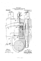
- FIG. 1 is a sectional elevation of my improved bearing construction.
- Fig. 2. a sectional plan view thereof.
- Fig. 3. a View similar to Fig. 1 but showing a modification, and Fig. 4. another view similar to Fig. 1 but showing another modification.
- 0 represents the body or principal part of the cap, which is held down to a frame or standard 8, in the usual manner by bolts 1;.
- the body of the cap 0 is, in each case, bored out to receive a brass liner n, in which a hydraulic ram or plunger device m has an accurate sliding fit.
- ram or plunger device m bears directly upon a block 70, which in turn bears upon the upper half of a bearing g, the latter resting on the shaft 1 of a crushing roll.
- the liquid or hydraulic pressure medium is introduced through a pipe h which passes through the cap o and communicates with a hydraulic pressure chamber 7L and in order to prevent leakage of pressure liquid from bet-ween the liner n and the ram or plunger device m, the ram or plunger device is constructed with three U-shaped leather packing rings 10 11, and a of these the lower leather ring a is held in position by the junk ring Z, and the two upper leather rings a and u by the plate 6 secured to the body of the ram or plunger device m and junk ring Z by screws 25.
- Each of the leather packing rings may be further provided with a metallic ring as shown at c, in Figs. 1 and 4, for the purpose of assisting to maintain the leather rings in position.
- I either provide the cap 0 with a cover as shown at o, Figs. 1 and 2; or, I provide the bearing-cap with a slab cover as shown at a, Fig. 4;; in either of these forms of bearing-cap I provide the underside of the cover with a leather packing ring U-shaped in cross section and retaining plate as shown at u and e, to prevent leakage.
- a hydraulic pressure bearing for crushing mills comprising a cylindrical pressure chamber open at one end and closed at the other, the closed end being provided with a central inlet, a plunger movable in the open end of said chamber and the inner end of which is provided with a central projection, a junk ring mounted on said central projection and a cap plate secured to said projection and holding said junk ring in position, said junk ring being provided in its outer face with annular concentric grooves, and annular packing-s placed in said grooves and held in place by said cap plate, one of said packing rings bearing on the wall of said chamber and the other on the central projection of the plunger, the body of the plunger being also provided with an annular groove in which is placed an annular packingwhich is held in position by the junk ring and which bears on the wall of said chamber.
- a hydraulic pressure bearing for CI'llSh'. ing mills comprising a body portion having a cylindrical pressure chamber open at one end and closed at the other by a capsecured I to the body portion, a plunger movable in i the open end of said chamber and the inner end of which is provided with a central projection, a junk ring mounted on said projection and held in place by a cap plate secured to said projection, said junk ring being provided with annular concentric grooves in which are placed annular packings held in position by said cap plate, and one of which bears on the wall of said chamber and the other on the projection of the plunger, the body of the plunger being also provided with an annular groove in which is placed an annular packing which is held in position by the junk ring and which bears on the Wall of said chamber and the cap which closes one end of said chamber being provided with an annular groove in which is placed an annular packing held in position by a plate secured to said cap and which bears on the wall of said chamber, and said cap being also provided with a
Landscapes
- Engineering & Computer Science (AREA)
- General Engineering & Computer Science (AREA)
- Mechanical Engineering (AREA)
- Coloring Foods And Improving Nutritive Qualities (AREA)
Description
W. MAXWELL. BEARING FOR SUGAR CANE URUSHING MILLS.
APPLICATION FILED 1330.6 1909. 995,699. I
w fl! M W MAXWELL BEARING FOR SUGAR CANE GRUSHING MILLS.
APPLICATION FILED DEC. 6, 1909.
Patented June 20, 1911.
3 SHEETS-SHEET 2.
, W. MAXWELL.
BEARING FOR SUGAR CANE GRUSHING MILLS.
APPLICATION FILED DEC. 6, 1909.
995,699, Patented June 20,1911.
3 SHEBTS-SHEBT 3.
llll
imrrn BEARING FOR SUGAR-CANE-CRUSHING MILLS.
To all whom t-t may concern:
Be it known that I, WVILLIAM MAXWELL, a subject of the King of Great Britain, and residing at Sydenham, in the county of Surrey, England, have invented certain new and useful Improvements in Bearings for Sugarcane-Crushing Mills, of which the following is a specification, such as will enable those skilled in the art to which it appcrtains to make and use the same.
This invention relates to sugar-cane crushing mills and the object thereof is to provide improved bearings for the rollers of mills of this class, or one of said rollers, a further object being to provide bearings of the class specified which employ hydraulic pressure to hold the roller or rollers up to their Work; and my invention particularly relates to means for preventing the leakage of the liquid used in such bearings for pro ducing the hydraulic pressure required.
In my improvement I accomplish the desired object by the use of an improved construction of bearing-cap having a hydraulic ram or plunger device as a means for regulating the pressure it is required to exercise on one or more of the crushing rollers used in a mill of the class specified, and I prevent leakage of the pressure liquid from such bearing by the employment of an improved form of hydraulic ram or plunger device having a compound or multiple series of U-shaped packing rings preferably composed of leather and suitably held in position.
The invention is fully disclosed in the following specification of which the accompanying drawing forms a part, in which the separate parts of my improvement are des ignated by suitable reference characters in each of the views, and in which Figure 1 is a sectional elevation of my improved bearing construction. Fig. 2. a sectional plan view thereof. Fig. 3. a View similar to Fig. 1 but showing a modification, and Fig. 4. another view similar to Fig. 1 but showing another modification.
In each of the three modified forms of bearing-cap as shown in Figs. 1, 2, 3, and 4:, 0 represents the body or principal part of the cap, which is held down to a frame or standard 8, in the usual manner by bolts 1;. The body of the cap 0 is, in each case, bored out to receive a brass liner n, in which a hydraulic ram or plunger device m has an accurate sliding fit. The lower end of the Specification of Letters'Patent.
Application filed December 6, 1909.
Patented June 20, 1911.
Serial No. 531,511.
ram or plunger device m bears directly upon a block 70, which in turn bears upon the upper half of a bearing g, the latter resting on the shaft 1 of a crushing roll.
The liquid or hydraulic pressure medium is introduced through a pipe h which passes through the cap o and communicates with a hydraulic pressure chamber 7L and in order to prevent leakage of pressure liquid from bet-ween the liner n and the ram or plunger device m, the ram or plunger device is constructed with three U-shaped leather packing rings 10 11, and a of these the lower leather ring a is held in position by the junk ring Z, and the two upper leather rings a and u by the plate 6 secured to the body of the ram or plunger device m and junk ring Z by screws 25. Each of the leather packing rings may be further provided with a metallic ring as shown at c, in Figs. 1 and 4, for the purpose of assisting to maintain the leather rings in position.
To facilitate the removal of the bearing ram or plunger device m, I either provide the cap 0 with a cover as shown at o, Figs. 1 and 2; or, I provide the bearing-cap with a slab cover as shown at a, Fig. 4;; in either of these forms of bearing-cap I provide the underside of the cover with a leather packing ring U-shaped in cross section and retaining plate as shown at u and e, to prevent leakage.
In cases where it is not desirable to use a cover as shown at Q), or a in Figs. 1, 2 and 4, for the removal of the ram or plunger device, I construct the body of the bearing-cap c as shown in Fig. 3. In this form of bearing-cap I provide the liner n with a neck extension n, which is continued up through the body 0 of the bearing-cap to form a connection with the pressure supply pipe h by means of a union coupling 11. I, however, prefer to connect up the pressure supply in the manner shown at h in Figs. 1, 2 and 1.
I am aware that prior to my invention, sugar-cane crushing mills have been made with compensating bearings by which it has been possible to hold the rolls up to one another by pressure controllable by a hydraulic ram or plunger device; but
Having fully described my invention what I claim as new, and desire to secure by Letters Patent is 1. A hydraulic pressure bearing for crushing mills, comprising a cylindrical pressure chamber open at one end and closed at the other, the closed end being provided with a central inlet, a plunger movable in the open end of said chamber and the inner end of which is provided with a central projection, a junk ring mounted on said central projection and a cap plate secured to said projection and holding said junk ring in position, said junk ring being provided in its outer face with annular concentric grooves, and annular packing-s placed in said grooves and held in place by said cap plate, one of said packing rings bearing on the wall of said chamber and the other on the central projection of the plunger, the body of the plunger being also provided with an annular groove in which is placed an annular packingwhich is held in position by the junk ring and which bears on the wall of said chamber.
2. A hydraulic pressure bearing for CI'llSh'. ing mills, comprising a body portion having a cylindrical pressure chamber open at one end and closed at the other by a capsecured I to the body portion, a plunger movable in i the open end of said chamber and the inner end of which is provided with a central projection, a junk ring mounted on said projection and held in place by a cap plate secured to said projection, said junk ring being provided with annular concentric grooves in which are placed annular packings held in position by said cap plate, and one of which bears on the wall of said chamber and the other on the projection of the plunger, the body of the plunger being also provided with an annular groove in which is placed an annular packing which is held in position by the junk ring and which bears on the Wall of said chamber and the cap which closes one end of said chamber being provided with an annular groove in which is placed an annular packing held in position by a plate secured to said cap and which bears on the wall of said chamber, and said cap being also provided with a central inlet.
In testimony that I claim the foregoing as my invention I have signed my name in presence of the subscribing witnesses this i 5th day of November 1909.
WILLIAM MAXWELL.
WVitnesses FRANCIS MAXWELL, MARIUS MAXWELL.
Copies of this patent may be obtained for five cents each, by addressing the Commissioner of Patents. Washington, D. G.
Priority Applications (1)
| Application Number | Priority Date | Filing Date | Title |
|---|---|---|---|
| US53151109A US995699A (en) | 1909-12-06 | 1909-12-06 | Bearing for sugar-cane-crushing mills. |
Applications Claiming Priority (1)
| Application Number | Priority Date | Filing Date | Title |
|---|---|---|---|
| US53151109A US995699A (en) | 1909-12-06 | 1909-12-06 | Bearing for sugar-cane-crushing mills. |
Publications (1)
| Publication Number | Publication Date |
|---|---|
| US995699A true US995699A (en) | 1911-06-20 |
Family
ID=3064031
Family Applications (1)
| Application Number | Title | Priority Date | Filing Date |
|---|---|---|---|
| US53151109A Expired - Lifetime US995699A (en) | 1909-12-06 | 1909-12-06 | Bearing for sugar-cane-crushing mills. |
Country Status (1)
| Country | Link |
|---|---|
| US (1) | US995699A (en) |
-
1909
- 1909-12-06 US US53151109A patent/US995699A/en not_active Expired - Lifetime
Similar Documents
| Publication | Publication Date | Title |
|---|---|---|
| US995699A (en) | Bearing for sugar-cane-crushing mills. | |
| US4291447A (en) | Controlled deflection roll | |
| US775923A (en) | Thrust-bearing. | |
| US223029A (en) | Improvement in adjustable bearings | |
| US775572A (en) | Tool for finishing flanged pipe. | |
| US1101757A (en) | Hydraulic pressure-regulator. | |
| US602287A (en) | Thomas w | |
| US705839A (en) | Thrust-bearing. | |
| US1100403A (en) | Lubricating journal-box. | |
| US444517A (en) | Hub-attaching device for vehicle-axles | |
| US385266A (en) | Anti-friction journal-bearing | |
| US628314A (en) | Thrust-bearing for grinding-mills. | |
| US206622A (en) | Improvement in cane-mills | |
| US48686A (en) | Improvement in metallic packing-boxes | |
| US1071646A (en) | Sugar-cane and like mill. | |
| US698944A (en) | Roller-bearing. | |
| US703542A (en) | Pulverizer. | |
| US23704A (en) | Journal-box | |
| US117217A (en) | Improvement in journal-boxes and axle-bearings | |
| US587248A (en) | William j | |
| US1023355A (en) | Bearing for mill-rolls. | |
| US637327A (en) | Rolls. | |
| US759497A (en) | Quartz-mill. | |
| US617550A (en) | Johannes appel | |
| US584893A (en) | Roller-bearing |