US9950396B2 - Method and apparatus for repairing conveyor chain - Google Patents

Method and apparatus for repairing conveyor chain Download PDF

Info

Publication number
US9950396B2
US9950396B2 US14/732,535 US201514732535A US9950396B2 US 9950396 B2 US9950396 B2 US 9950396B2 US 201514732535 A US201514732535 A US 201514732535A US 9950396 B2 US9950396 B2 US 9950396B2
Authority
US
United States
Prior art keywords
chain
repair
track
anvil
punch
Prior art date
Legal status (The legal status is an assumption and is not a legal conclusion. Google has not performed a legal analysis and makes no representation as to the accuracy of the status listed.)
Active, expires
Application number
US14/732,535
Other versions
US20160354876A1 (en
Inventor
Charles C. Frost
Charles J. Deschaine
Keith Miller
Current Assignee (The listed assignees may be inaccurate. Google has not performed a legal analysis and makes no representation or warranty as to the accuracy of the list.)
Frost Tech LLC
Original Assignee
Frost Tech LLC
Priority date (The priority date is an assumption and is not a legal conclusion. Google has not performed a legal analysis and makes no representation as to the accuracy of the date listed.)
Filing date
Publication date
Application filed by Frost Tech LLC filed Critical Frost Tech LLC
Priority to US14/732,535 priority Critical patent/US9950396B2/en
Assigned to FROST TECH LLC reassignment FROST TECH LLC ASSIGNMENT OF ASSIGNORS INTEREST (SEE DOCUMENT FOR DETAILS). Assignors: DESCHAINE, CHARLES J, FROST, CHARLES C, MILLER, KEITH
Publication of US20160354876A1 publication Critical patent/US20160354876A1/en
Application granted granted Critical
Publication of US9950396B2 publication Critical patent/US9950396B2/en
Active legal-status Critical Current
Adjusted expiration legal-status Critical

Links

Images

Classifications

    • BPERFORMING OPERATIONS; TRANSPORTING
    • B23MACHINE TOOLS; METAL-WORKING NOT OTHERWISE PROVIDED FOR
    • B23PMETAL-WORKING NOT OTHERWISE PROVIDED FOR; COMBINED OPERATIONS; UNIVERSAL MACHINE TOOLS
    • B23P6/00Restoring or reconditioning objects
    • YGENERAL TAGGING OF NEW TECHNOLOGICAL DEVELOPMENTS; GENERAL TAGGING OF CROSS-SECTIONAL TECHNOLOGIES SPANNING OVER SEVERAL SECTIONS OF THE IPC; TECHNICAL SUBJECTS COVERED BY FORMER USPC CROSS-REFERENCE ART COLLECTIONS [XRACs] AND DIGESTS
    • Y10TECHNICAL SUBJECTS COVERED BY FORMER USPC
    • Y10TTECHNICAL SUBJECTS COVERED BY FORMER US CLASSIFICATION
    • Y10T29/00Metal working
    • Y10T29/49Method of mechanical manufacture
    • Y10T29/49718Repairing
    • Y10T29/49721Repairing with disassembling
    • Y10T29/49723Repairing with disassembling including reconditioning of part

Definitions

  • Overhead conveyor chains are used in numerous manufacturing and processing industries. They comprise links joined by link pins, and include bearing wheels which ride on supporting tracks. They may extend for several hundred to several thousand feet. A typical cost of a new chain is $60 per foot. Accordingly, manufacturers and processors like to maintain the useful life of a chain as much as possible. 14 years is a typical chain life.
  • Chains suffering from link pin wear are often repaired by using a “come along” secured at its opposite ends to spaced portions on the conveyor chain.
  • the “come along” is tightened against the take up force applied to the chain. This loosens the chain between the come along securing points, allowing the removal and replacement of worn parts.
  • the entire chain may be removed from its track. Worn pins, wheels or other components are removed and replaced with new counterparts.
  • the cost to remove and either repair or replace chain is significant, e.g. $10-$12 per foot.
  • the process typically takes 24 hours, 12 hours to remove, and 12 hours or more to repair or replace with a new chain, and if repaired, 12 hours more to replace the repaired chain.
  • 36 hours of production down time means 36 hours of lost profit.
  • the present invention comprises a method and apparatus for repairing overhead conveyor chain by removing a section of track, locating a mobile repair station under the exposed chain, and effecting the needed repair on the chain by cycling the intact chain past the mobile repair station and repairing it as it passes.
  • a chain can be repaired at about 20% of the cost of removing an old chain and replacing it with a new chain, and can be accomplished in about 1 ⁇ 3 of the time it takes to remove and replace an old chain.
  • FIG. 1 is an elevation of a portion of a conveyor chain moving along its track, with a section of track removed and a repair station positioned underneath the unsupported section of chain;
  • FIG. 2 is an enlarged perspective view of a small section of conveyor chain
  • FIG. 3 is an elevated perspective view of a repair station with a swaging unit positioned on the repair table;
  • FIG. 4 is a plan view of the repair station of FIG. 3 ;
  • FIG. 5 is an enlarged side elevational view of the re-swaging unit
  • FIG. 6 is a cross sectional view taken along plane VI-VI of FIG. 5 ;
  • FIG. 7 is a cross sectional view taken along plane VII-VII of FIG. 5 ;
  • FIG. 8 is a cross sectional view taken along plane VIII-VIII on FIG. 5 ;
  • FIG. 9 is a cross sectional view taken along plane IX-IX of FIG. 8 ;
  • FIG. 10 is a perspective view of a link repair station
  • FIG. 11 is a top plan view of a portion of a link repair station with a conveyor chain passing through the repair station;
  • FIG. 12 is a top plan view of a portion of the link repair station.
  • FIG. 13 is a perspective view of a chain clamp of the link repair station.
  • a section 10 a of conveyor track 10 is removed, leaving a section of conveyor chain 20 exposed ( FIG. 1 ).
  • a repair table 30 is placed under chain 20 where track section 10 a has been removed. The chain is cycled passed repair table 30 and repaired, without having to remove the chain from track 10 .
  • the “components list” (Table 1) sets forth the various components and their identifying numbers which will be described in further detail:
  • Track 10 shown herein is of an I-beam configuration, with each section having a flange 11 which is bolted to the flange 11 of the next adjacent track section ( FIG. 1 ).
  • the track sections are 5-10 feet in length.
  • Conveyor chains come in various configurations as well.
  • the particular conveyor chain illustrated in the present embodiments comprises a plurality of center links 21 joined to adjacent side links 22 by means of link pins 23 ( FIG. 2 ).
  • the link pins 23 shown in these embodiments include upstanding mounts 24 for mounting other items, such as supporting platforms for conveyed articles.
  • a wheel 26 is positioned on each side of a center link 21 , with an axle 26 a passing through each of the load bearing wheels 26 and through center link 21 .
  • a horizontally oriented guide wheel 25 is positioned between each pair of opposed side links 22 .
  • Each load bearing wheel 26 comprises a center axle 26 a , an inner race 26 b carried on axle 26 a , an outer race 26 c , and a plurality of bearing rollers or balls 26 d carried between the races.
  • the outer rim of wheel 26 is mounted on outer race 26 c .
  • the inner races 26 b are swaged to axle 26 a by pressing the hub ends of the axle between a punch and an anvil. The punch creates a small indentation 26 e on one hub end of axle 26 a , as shown in FIG. 2 .
  • link pins 23 become worn through engagement with the center links 21 and their adjacent side links 22 , and require replacement from time to time.
  • the wear life of link pins 23 can be extended by using repositionable link pins as shown for example in U.S. Pat. No. 7,726,469. These pins can be “repaired” by rotating them between three different positions and three different wear surfaces, as each wear surface has become overly worn.
  • Repair station 30 of the preferred embodiment comprises a repair table 31 having a work surface 31 a mounted atop telescoping legs 32 ( FIG. 3 ). Legs 32 may optionally be provided with casters or wheels to enhance the mobility of the repair station. A supporting roller 33 is optionally positioned at one or each end of work surface 31 . A repair unit, such as swage repair unit 40 shown in FIG. 3 or pin repair unit 70 as shown in FIGS. 10-13 , is positioned on top of repair station work surface 31 .
  • Repair station 30 may also comprise spaced mobile supports 34 ( FIG. 10 ), each comprising a base 34 a , underlying wheels or casters 34 b , upstanding telescoping legs 34 c , a top platform 34 d and locator blocks 34 e .
  • spaced mobile supports 34 can be used alone or in conjunction with repair table 31 .
  • Swage repair unit 40 comprises a pair of spaced slides 41 mounted between end blocks 41 a ( FIG. 3 ).
  • a swage unit mounting platform 42 is slidably carried on slides 41 such that unit 40 can be repositioned along the length of the slides 41 .
  • a sturdy upwardly opening “U” shaped mounting bracket 43 is mounted to platform 42 .
  • One of the upturned legs of bracket 43 terminates in a sturdy circular mounting band 43 a , which surrounds and firmly holds cylinder 51 of swage punch 50 in place.
  • the opposite upturned leg of bracket 43 terminates in a semi-circular mounting band 43 b , which embraces and supports swage anvil unit 60 ( FIGS. 3 and 4 ).
  • a section of track support 44 having sloping end portions 44 a ( FIGS.
  • end plates 45 are mounted on the upturned legs of bracket 43 , and are held against spreading movement by tie bars 46 passing through and between them, and secured in place by nuts 47 on either end of tie bars 46 ( FIGS. 4, 5 and 7 ).
  • Swaging punch unit 50 comprises a punch cylinder 51 which contains a piston 52 having a punch insert 53 mounted in the end thereof ( FIGS. 5, 6, 8 and 9 ).
  • Punch insert 53 includes a projecting tip 53 a which actually does the swaging work of punch unit 50 .
  • Punch unit 50 also includes a sliding wheel locating sleeve 54 which can be manually slid along the outside of punch cylinder 51 and into position with its end portion 54 a capturing a load bearing wheel 26 , as shown in FIG. 9 .
  • Anvil unit 60 comprises a cylindrically shaped anvil base 63 ( FIGS. 5, 7, 8 and 9 ), which is mounted in, and is securely held in place, by the semi-circular anvil mounting band 43 b , which comprises the upper end of one of the upstanding legs of mounting bracket 43 . This anchors anvil unit 60 in its place.
  • a mounting plate 62 abuts and is secured to the face of anvil base 63 .
  • Anvil plate 61 abuts and is secured to mounting plate 62 ( FIGS. 5, 7, 8 and 9 ).
  • Mounting plate 62 extends down below anvil plate 61 and provides a mount for chain track 44 ( FIG. 5 ).
  • Chain track 44 is mounted to and projects from the face of mounting plate 62 . It is also mounted to the bottom of anvil plate 61 , which it passes beneath.
  • Anvil insert 61 a is positioned in anvil plate 61 ( FIGS. 7, 8 and 9 ).
  • Anvil insert 61 a includes a circular projection 61 b which actually engages the hub end of a wheel axel 26 a during the re-swaging operation.
  • Projection 61 b projects slightly beyond the face of anvil insert 61 a and anvil plate 61 , such that it projects into the slight recess in the center outside face of wheel 26 , where the hub end of wheel axel 26 a is located. It also helps keep a small space between anvil plate 61 and wheel 26 during the re-swaging “punch,” minimizing the possibility of damage to wheel 26 ( FIG. 9 ).
  • Spaced push pins 64 are slideably positioned in a bore which passes through anvil plate 61 , mounting plate 62 , and into anvil base 63 ( FIGS. 7, 8 AND 9 ).
  • the bore is slightly large in diameter in mounting plate 62 and anvil base 63 , so as to accommodate the enlarged “hat” end of push pins 64 .
  • Pins 64 are biased outwardly by springs 65 positioned behind them, such that they project out from the face of anvil plate 61 , and extend slightly into the space above chain track 64 .
  • the enlarged hat ends on pins 64 keep them from being pushed out too far, or altogether.
  • repair station 30 In operation, track section 10 a is removed and repair station 30 with swaging unit 40 attached is positioned beneath the now exposed section of chain 20 .
  • Repair station 40 is located such that chain 20 rests on chain support track 44 of swage repair unit 40 , between swaging punch 50 and swaging anvil 60 ( FIGS. 4, 8 and 9 ).
  • a wheel 26 to be re-swaged is approximately located by moving chain 20 . Wheel 26 can be more precisely positioned in re-swaging position by sliding swage repair unit 40 back or forth along slides 41 ( FIGS. 3, 4 ).
  • wheel locating sleeve 54 is slid forward on cylinder 51 until its end portion 54 a captures wheel 26 and holds it in place as shown in FIG. 9 .
  • the end portion 54 a of sleeve 54 is cut away at 54 b , such that it is easier for an operator to see that wheel 26 is properly located as sleeve 54 is slid forward over wheel 26 .
  • the projecting anvil push pins 64 help keep wheels 26 and center link 21 properly aligned as one of the wheels 26 is captured by wheel capturing sleeve 54 . Once a link 21 and its opposed wheels 26 are thus located ( FIG.
  • punch piston 52 is driven forward so that punch tip 53 a strikes hard against the hub end of axle 26 a .
  • the projecting portions of said anvil and said punch which engage the opposite ends of an axel to be re-swaged, project far enough out from said punch and said anvil that the surrounding portions of said anvil and said punch do not compress the wheel being repaired except at said axel to be swaged.
  • the pin repair unit 70 comprises an elongated upwardly opening C-shaped channel 71 , through which chain 20 passes ( FIGS. 10-12 ).
  • Repair station 70 can be used alone as shown in FIG. 10 , or in conjunction with repair table 31 . Swaging unit 40 would be removed from table 31 , and chain channel 71 would rest on and pass over roller of rollers 33 on repair table 31 .
  • Channel 71 includes an open slot 72 in its bottom wall, through which the heads of pins can pass as chain 20 passes through channel 71 .
  • the slots 72 extend from each end and open into an enlarged opening 73 which facilitates greater access to the link pins 23 of chain 20 .
  • the end portions 71 a of the sidewalls of channel 71 are flared outwardly to define a funneling end which helps feed chain 20 into and out of channel 71 as it passes.
  • a pair of latches 75 are located generally at each end of the enlarged open area 73 in the bottom of channel 72 .
  • a clamping plate 75 b is pivotally mounted on a clamp mounting block 75 a , which in turn is mounted to the sidewall of track channel 71 .
  • chain 20 is advanced through channel 71 a portion at a time, with each portion covering the distance between clamps 75 .
  • Chain 26 is clamped in place by closing clamps 75 as shown in FIG. 11 .
  • the link pins between clamps 75 are either rotated to new wear positions or removed and replaced with new pins.
  • the chain is then advanced until another portion of chain 20 which has not yet been serviced is locked in position between clamps 75 .

Landscapes

  • Engineering & Computer Science (AREA)
  • Mechanical Engineering (AREA)
  • Automatic Assembly (AREA)

Abstract

A method and apparatus for repairing overhead conveyor chain by removing a section of track, locating a mobile repair station under the exposed track, and effecting the needed repair on the chain by cycling the intact chain past the mobile repair station and repairing it as it passes. Repair embodiments include re-swaging and repair, replacement or rotation of chain links.

Description

FIELD OF THE INVENTION
The present invention relates to the field of repairing overhead conveyor chains
BACKGROUND OF THE INVENTION
Overhead conveyor chains are used in numerous manufacturing and processing industries. They comprise links joined by link pins, and include bearing wheels which ride on supporting tracks. They may extend for several hundred to several thousand feet. A typical cost of a new chain is $60 per foot. Accordingly, manufacturers and processors like to maintain the useful life of a chain as much as possible. 14 years is a typical chain life.
One limiting factor on chain life is loosening of the swage connection of the bearing wheel axel to the inner race of the bearing wheel on either side of a chain link. This requires replacement of the affected wheels. Another limiting factor is wear on the link pins, which eventually have to be replaced.
Chains suffering from link pin wear are often repaired by using a “come along” secured at its opposite ends to spaced portions on the conveyor chain. The “come along” is tightened against the take up force applied to the chain. This loosens the chain between the come along securing points, allowing the removal and replacement of worn parts.
Where extensive repairs are required, the entire chain may be removed from its track. Worn pins, wheels or other components are removed and replaced with new counterparts. The cost to remove and either repair or replace chain is significant, e.g. $10-$12 per foot. The process typically takes 24 hours, 12 hours to remove, and 12 hours or more to repair or replace with a new chain, and if repaired, 12 hours more to replace the repaired chain. In addition, 36 hours of production down time means 36 hours of lost profit.
SUMMARY OF THE INVENTION
The present invention comprises a method and apparatus for repairing overhead conveyor chain by removing a section of track, locating a mobile repair station under the exposed chain, and effecting the needed repair on the chain by cycling the intact chain past the mobile repair station and repairing it as it passes. As a result of this invention, a chain can be repaired at about 20% of the cost of removing an old chain and replacing it with a new chain, and can be accomplished in about ⅓ of the time it takes to remove and replace an old chain.
These and other aspects, advantages and features of the invention will be more fully understood and appreciated by reference to the written description of the preferred embodiments and appended drawings.
BRIEF DESCRIPTION OF THE DRAWINGS
FIG. 1 is an elevation of a portion of a conveyor chain moving along its track, with a section of track removed and a repair station positioned underneath the unsupported section of chain;
FIG. 2 is an enlarged perspective view of a small section of conveyor chain;
FIG. 3 is an elevated perspective view of a repair station with a swaging unit positioned on the repair table;
FIG. 4 is a plan view of the repair station of FIG. 3;
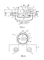
FIG. 5 is an enlarged side elevational view of the re-swaging unit;
FIG. 6 is a cross sectional view taken along plane VI-VI of FIG. 5;
FIG. 7 is a cross sectional view taken along plane VII-VII of FIG. 5;
FIG. 8 is a cross sectional view taken along plane VIII-VIII on FIG. 5;
FIG. 9 is a cross sectional view taken along plane IX-IX of FIG. 8;
FIG. 10 is a perspective view of a link repair station;
FIG. 11 is a top plan view of a portion of a link repair station with a conveyor chain passing through the repair station;
FIG. 12 is a top plan view of a portion of the link repair station; and
FIG. 13 is a perspective view of a chain clamp of the link repair station.
DESCRIPTION OF THE PREFERRED EMBODIMENTS
In the preferred embodiments, a section 10 a of conveyor track 10 is removed, leaving a section of conveyor chain 20 exposed (FIG. 1). A repair table 30 is placed under chain 20 where track section 10 a has been removed. The chain is cycled passed repair table 30 and repaired, without having to remove the chain from track 10. The “components list” (Table 1) sets forth the various components and their identifying numbers which will be described in further detail:
TABLE 1
Components List
Conveyor track
10
Conveyor track section 10a
Coveyor chain 20
Center link 21
Side links 22
Link pins 23
Link pin mounting extension 24
Guide wheels 25
Load wheels 26
Axel 26a
Inner race 26b
Outer race 26c
Bearings
26d
Swaging detent
26e
Mobile Repair Station 30
Repair table 31
Table work surface 31a
Telescoping legs 32
Roller 33
Mobile supports 34
Base 34a
Wheels 34b
Telescoping legs 34c
Top platform 34d
Locator blocks
34e
Swage repair unit 40
Slides 41
Slide end blocks 41a
Swage platform
42
Mounting bracket 43
Punch mounting band 43a
Anvil mounting band 43b
Chain track
44
End plates 45
Tie bars 46
nuts 47
Punch unit 50
Punch cylinder 51
Punch piston 52
Punch insert 53
Punch tip 53a
Wheel capture sleeve 54
End portion 54a
Anvil unit 60
Anvil plate 61
Anvil insert 61a
Anvil projection 61b
Mounting plate 62
Anvil base 63
Push pins 64
Push pin springs 65
Pin repair unit 70
Chain support channel 71
Funneled end 71a
Bottom slot 72
Bottom opening 73
Chain clamps 75
The tracks used in overhead conveyor systems have various configurations. Track 10 shown herein is of an I-beam configuration, with each section having a flange 11 which is bolted to the flange 11 of the next adjacent track section (FIG. 1). Typically, the track sections are 5-10 feet in length.
Conveyor chains come in various configurations as well. The particular conveyor chain illustrated in the present embodiments comprises a plurality of center links 21 joined to adjacent side links 22 by means of link pins 23 (FIG. 2). The link pins 23 shown in these embodiments include upstanding mounts 24 for mounting other items, such as supporting platforms for conveyed articles. A wheel 26 is positioned on each side of a center link 21, with an axle 26 a passing through each of the load bearing wheels 26 and through center link 21. In chain 20 shown in the present embodiments, a horizontally oriented guide wheel 25 is positioned between each pair of opposed side links 22.
Each load bearing wheel 26 comprises a center axle 26 a, an inner race 26 b carried on axle 26 a, an outer race 26 c, and a plurality of bearing rollers or balls 26 d carried between the races. The outer rim of wheel 26 is mounted on outer race 26 c. The inner races 26 b are swaged to axle 26 a by pressing the hub ends of the axle between a punch and an anvil. The punch creates a small indentation 26 e on one hub end of axle 26 a, as shown in FIG. 2.
Over time, the swaged connection between axel 26 a and inner race 26 b can become loosened, creating wear between inner race 26 b and axle 26 a, and ultimately leading to disintegration of the wheel. Similarly as noted above, the link pins 23 become worn through engagement with the center links 21 and their adjacent side links 22, and require replacement from time to time. The wear life of link pins 23 can be extended by using repositionable link pins as shown for example in U.S. Pat. No. 7,726,469. These pins can be “repaired” by rotating them between three different positions and three different wear surfaces, as each wear surface has become overly worn.
Repair station 30 of the preferred embodiment comprises a repair table 31 having a work surface 31 a mounted atop telescoping legs 32 (FIG. 3). Legs 32 may optionally be provided with casters or wheels to enhance the mobility of the repair station. A supporting roller 33 is optionally positioned at one or each end of work surface 31. A repair unit, such as swage repair unit 40 shown in FIG. 3 or pin repair unit 70 as shown in FIGS. 10-13, is positioned on top of repair station work surface 31.
Repair station 30 may also comprise spaced mobile supports 34 (FIG. 10), each comprising a base 34 a, underlying wheels or casters 34 b, upstanding telescoping legs 34 c, a top platform 34 d and locator blocks 34 e. Such spaced mobile supports 34 can be used alone or in conjunction with repair table 31.
Swage repair unit 40 comprises a pair of spaced slides 41 mounted between end blocks 41 a (FIG. 3). A swage unit mounting platform 42 is slidably carried on slides 41 such that unit 40 can be repositioned along the length of the slides 41. A sturdy upwardly opening “U” shaped mounting bracket 43 is mounted to platform 42. One of the upturned legs of bracket 43 terminates in a sturdy circular mounting band 43 a, which surrounds and firmly holds cylinder 51 of swage punch 50 in place. The opposite upturned leg of bracket 43 terminates in a semi-circular mounting band 43 b, which embraces and supports swage anvil unit 60 (FIGS. 3 and 4). A section of track support 44 having sloping end portions 44 a (FIGS. 5, 7, 8 and 9) extends from anvil unit 60 into the space between anvil unit 60 and punch unit 50, for supporting chain 20 as it passes by. A depression 44 b is formed in track 44 in the space adjacent punch unit 50 (FIGS. 3, 8 and 9). This leaves the punch side wheel 26 unsupported and free for capture by the end portion 54 a of capture sleeve 54 (FIGS. 5, 8 and 9).
To help reinforce and hold the punch unit 50 and anvil unit 60 from spreading when punch 50 is activated, end plates 45 are mounted on the upturned legs of bracket 43, and are held against spreading movement by tie bars 46 passing through and between them, and secured in place by nuts 47 on either end of tie bars 46 (FIGS. 4, 5 and 7).
Swaging punch unit 50 comprises a punch cylinder 51 which contains a piston 52 having a punch insert 53 mounted in the end thereof (FIGS. 5, 6, 8 and 9). Punch insert 53 includes a projecting tip 53 a which actually does the swaging work of punch unit 50. Punch unit 50 also includes a sliding wheel locating sleeve 54 which can be manually slid along the outside of punch cylinder 51 and into position with its end portion 54 a capturing a load bearing wheel 26, as shown in FIG. 9.
Anvil unit 60 comprises a cylindrically shaped anvil base 63 (FIGS. 5, 7, 8 and 9), which is mounted in, and is securely held in place, by the semi-circular anvil mounting band 43 b, which comprises the upper end of one of the upstanding legs of mounting bracket 43. This anchors anvil unit 60 in its place.
A mounting plate 62 abuts and is secured to the face of anvil base 63. Anvil plate 61 abuts and is secured to mounting plate 62 (FIGS. 5, 7, 8 and 9). Mounting plate 62 extends down below anvil plate 61 and provides a mount for chain track 44 (FIG. 5). Chain track 44 is mounted to and projects from the face of mounting plate 62. It is also mounted to the bottom of anvil plate 61, which it passes beneath.
Anvil insert 61 a is positioned in anvil plate 61 (FIGS. 7, 8 and 9). Anvil insert 61 a includes a circular projection 61 b which actually engages the hub end of a wheel axel 26 a during the re-swaging operation. Projection 61 b projects slightly beyond the face of anvil insert 61 a and anvil plate 61, such that it projects into the slight recess in the center outside face of wheel 26, where the hub end of wheel axel 26 a is located. It also helps keep a small space between anvil plate 61 and wheel 26 during the re-swaging “punch,” minimizing the possibility of damage to wheel 26 (FIG. 9).
Spaced push pins 64 are slideably positioned in a bore which passes through anvil plate 61, mounting plate 62, and into anvil base 63 (FIGS. 7, 8 AND 9). The bore is slightly large in diameter in mounting plate 62 and anvil base 63, so as to accommodate the enlarged “hat” end of push pins 64. Pins 64 are biased outwardly by springs 65 positioned behind them, such that they project out from the face of anvil plate 61, and extend slightly into the space above chain track 64. The enlarged hat ends on pins 64 keep them from being pushed out too far, or altogether.
In operation, track section 10 a is removed and repair station 30 with swaging unit 40 attached is positioned beneath the now exposed section of chain 20. Repair station 40 is located such that chain 20 rests on chain support track 44 of swage repair unit 40, between swaging punch 50 and swaging anvil 60 (FIGS. 4, 8 and 9). A wheel 26 to be re-swaged is approximately located by moving chain 20. Wheel 26 can be more precisely positioned in re-swaging position by sliding swage repair unit 40 back or forth along slides 41 (FIGS. 3, 4).
With a wheel 26 located directly between swaging punch 50 and swaging anvil 60, wheel locating sleeve 54 is slid forward on cylinder 51 until its end portion 54 a captures wheel 26 and holds it in place as shown in FIG. 9. The end portion 54 a of sleeve 54 is cut away at 54 b, such that it is easier for an operator to see that wheel 26 is properly located as sleeve 54 is slid forward over wheel 26. The projecting anvil push pins 64 help keep wheels 26 and center link 21 properly aligned as one of the wheels 26 is captured by wheel capturing sleeve 54. Once a link 21 and its opposed wheels 26 are thus located (FIG. 8), punch piston 52 is driven forward so that punch tip 53 a strikes hard against the hub end of axle 26 a. This forces the opposite end of axle 26 a hard against anvil projection 61 b, and forces push pins 46 inwardly such that wheel 26 is hard against the end of anvil projection 61 b (FIG. 9). The projecting portions of said anvil and said punch which engage the opposite ends of an axel to be re-swaged, project far enough out from said punch and said anvil that the surrounding portions of said anvil and said punch do not compress the wheel being repaired except at said axel to be swaged.
This re-swages axle 26 to the inner races 26 b of wheels 26. With the wheels 26 thus reswaged, piston 52 withdraws and push pins 64 push wheel 26 away from anvil projection 61 b. Chain 20 is then advanced until the next set of wheels 26 are located approximately between anvil unit 60 and punch unit 53, and the operation afore described is repeated.
The pin repair unit 70 comprises an elongated upwardly opening C-shaped channel 71, through which chain 20 passes (FIGS. 10-12). Repair station 70 can be used alone as shown in FIG. 10, or in conjunction with repair table 31. Swaging unit 40 would be removed from table 31, and chain channel 71 would rest on and pass over roller of rollers 33 on repair table 31.
Channel 71 includes an open slot 72 in its bottom wall, through which the heads of pins can pass as chain 20 passes through channel 71. The slots 72 extend from each end and open into an enlarged opening 73 which facilitates greater access to the link pins 23 of chain 20. The end portions 71 a of the sidewalls of channel 71 are flared outwardly to define a funneling end which helps feed chain 20 into and out of channel 71 as it passes.
A pair of latches 75 are located generally at each end of the enlarged open area 73 in the bottom of channel 72. A clamping plate 75 b is pivotally mounted on a clamp mounting block 75 a, which in turn is mounted to the sidewall of track channel 71. When a chain 20 is moved into position for removing or rotating one or more link pins 23 positioned above opening 73, clamps 75 are rotated from their opened position as shown in FIG. 12 to their clamping position as shown in FIG. 11, where the generally V-shaped end 75 c of clamping plate 75 b engages a guide roller 25 of chain 20. With chain 20 thus locked in place, link pins 23 which are positioned between chain clamps 75 can be removed without losing control of the rest of chain 20.
In use, chain 20 is advanced through channel 71 a portion at a time, with each portion covering the distance between clamps 75. Chain 26 is clamped in place by closing clamps 75 as shown in FIG. 11. The link pins between clamps 75 are either rotated to new wear positions or removed and replaced with new pins. The chain is then advanced until another portion of chain 20 which has not yet been serviced is locked in position between clamps 75.
It will be understood that the forgoing is a description of preferred embodiments of the invention, and that various changes and alterations can be made without departing from the spirit of the invention.

Claims (12)

The invention claimed is:
1. A method for repairing overhead conveyor chain carried on an overhead track comprising: removing a section of track from said overhead track, thereby leaving a portion of said chain exposed; locating a repair station adjacent said exposed chain; and effecting the needed repairs on the chain by cycling said chain past the mobile repair station and repairing said chain as said chain passes.
2. The method of claim 1 in which said repair station comprises a telescoping base, and said step of locating includes adjusting the height of said repair station such that said repair station is adjacent said exposed chain.
3. The method of claim 1 in which said chain is carried on load bearing wheels as it travels on said overhead track, said load bearing wheels including an inner race fixed to a wheel axle by swaging; said step of locating a repair station includes providing said repair station with a swage repair unit; and said step of effecting repairs comprises re-swaging said connection between said wheel axle and said inner race.
4. The method of claim 3 in which said swage repair unit is provided with an anvil, a punch facing said anvil, and a chain support track positioned between said anvil and said punch; said step of effecting repair including positioning a load bearing wheel on said track between said anvil and said punch, and activating said punch to re-swage said wheel.
5. The method of claim 1 in which said chain includes links joined by link pins; said step of said step of locating a repair station includes providing said repair station with a link pin repair unit; and said step of effecting repairs comprises repairing, replacing or rotating said link pins.
6. The method of claim 1 in which said repair station includes a repair unit mounted on a slide, said slide being oriented parallel to the direction of travel of said chain; said method further including moving said chain such that a portion to be prepared is located approximately at said repair unit: and sliding said repair unit left or right on said slide to more precisely align said repair unit with said portion of said chain to be repaired.
7. The method of claim 1 in which said repair station includes a repair track for supporting chain to be repaired; said step of locating said repair station including positioning said repair track such that said repair track supports said exposed portion of said chain; providing said repair track with an opening which allows access to a portion of said chain to be repaired; and said step of effecting repair of said chain including repairing said chain through said opening in said track.
8. The method of claim 1 in which said repair station includes a repair track for supporting chain to be repaired; said step of locating said repair station including positioning said repair track such that said repair track supports said exposed portion of said chain; providing said repair track with at least two clamps spaced along the length of said track for clamping said chain against movement; said step of effecting repair of said chain including closing said clamps to clamp said chain against movement, and temporarily dismantling and repairing said chain at a location or locations between said clamps.
9. The method of claim 1 in which said chain is carried on load bearing wheels as it travels on said overhead track, said load bearing wheels including an inner race fixed to a wheel axle by swaging; said step of locating a repair station includes providing said repair station with a swage repair unit; said swage repair unit being provided with an anvil, a punch facing said anvil, and a chain support track positioned between said anvil and said punch; said swage unit being mounted on a slide, said slide being oriented parallel to the direction of travel of said chain; said method further including moving said chain such that a portion to be prepared is located approximately at said repair unit: and sliding said repair unit left or right on said slide to more precisely align said anvil and said punch with a load bearing wheel to be repaired; and said step of effecting repairs comprises activating said punch to re-swage said wheel.
10. A method for repairing conveyor chain of the type carried on a supporting track by load bearing wheels which include an inner race fixed to a wheel axle by swaging, said method comprising; re-swaging said wheels when said inner race has become loosened from said wheel axle, by placing a wheel between an anvil and a punch and activating said punch to re-swage said inner race to said wheel axle.
11. The method of claim 10 in which said wheels are affixed to chain links, and are re-swaged while they are still attached to a chain link.
12. The method of claim 11 which includes providing a repair station with a swage repair unit; said swage repair unit being provided with an anvil, a punch facing said anvil, and a chain support track positioned between said anvil and said punch; said re-swaging step including locating a chain link and associated wheel on said chain support track, such that said load bearing wheel is located between said anvil and said punch; and activating said punch to re-swage said wheel.
US14/732,535 2015-06-05 2015-06-05 Method and apparatus for repairing conveyor chain Active 2036-05-09 US9950396B2 (en)

Priority Applications (1)

Application Number Priority Date Filing Date Title
US14/732,535 US9950396B2 (en) 2015-06-05 2015-06-05 Method and apparatus for repairing conveyor chain

Applications Claiming Priority (1)

Application Number Priority Date Filing Date Title
US14/732,535 US9950396B2 (en) 2015-06-05 2015-06-05 Method and apparatus for repairing conveyor chain

Publications (2)

Publication Number Publication Date
US20160354876A1 US20160354876A1 (en) 2016-12-08
US9950396B2 true US9950396B2 (en) 2018-04-24

Family

ID=57450860

Family Applications (1)

Application Number Title Priority Date Filing Date
US14/732,535 Active 2036-05-09 US9950396B2 (en) 2015-06-05 2015-06-05 Method and apparatus for repairing conveyor chain

Country Status (1)

Country Link
US (1) US9950396B2 (en)

Cited By (1)

* Cited by examiner, † Cited by third party
Publication number Priority date Publication date Assignee Title
CN112122875A (en) * 2019-06-25 2020-12-25 山东华光光电子股份有限公司 Device and method for quickly correcting positioning ring of tube seat of semiconductor laser

Families Citing this family (4)

* Cited by examiner, † Cited by third party
Publication number Priority date Publication date Assignee Title
CN109894798B (en) * 2017-12-07 2020-05-22 中冶宝钢技术服务有限公司 Method for overhauling conveyor chain
US11046526B1 (en) * 2020-06-24 2021-06-29 Frost Tech Llc Conveyor guide wheel
DE102020130151B4 (en) 2020-11-16 2023-05-11 Dr. Ing. H.C. F. Porsche Aktiengesellschaft Mobile maintenance device
CN116652872B (en) * 2023-07-24 2025-09-09 宣化钢铁集团有限责任公司 High-speed line PF transmission chain replacement method

Citations (2)

* Cited by examiner, † Cited by third party
Publication number Priority date Publication date Assignee Title
US7726469B2 (en) 2002-03-08 2010-06-01 Frost Links, Inc. Conveyor chain
US20110016843A1 (en) * 2009-07-27 2011-01-27 Steven Richard Scott Vehicle chain repair device

Patent Citations (2)

* Cited by examiner, † Cited by third party
Publication number Priority date Publication date Assignee Title
US7726469B2 (en) 2002-03-08 2010-06-01 Frost Links, Inc. Conveyor chain
US20110016843A1 (en) * 2009-07-27 2011-01-27 Steven Richard Scott Vehicle chain repair device

Cited By (2)

* Cited by examiner, † Cited by third party
Publication number Priority date Publication date Assignee Title
CN112122875A (en) * 2019-06-25 2020-12-25 山东华光光电子股份有限公司 Device and method for quickly correcting positioning ring of tube seat of semiconductor laser
CN112122875B (en) * 2019-06-25 2022-05-10 山东华光光电子股份有限公司 Device and method for quickly correcting positioning ring of tube seat of semiconductor laser

Also Published As

Publication number Publication date
US20160354876A1 (en) 2016-12-08

Similar Documents

Publication Publication Date Title
US9950396B2 (en) Method and apparatus for repairing conveyor chain
US3255943A (en) Apparatus for fabricating wooden structures
US20190031258A1 (en) Track mounting tool
PL393489A1 (en) Method and apparatus for laser welding of metal post stems
AU2007221749B2 (en) Retrofit jig system for a truss assembly table
CN116637958B (en) Aluminum alloy profile cutting equipment
KR100596565B1 (en) Method of assembling motor vehicle body
US20030061697A1 (en) Pre-plating of wooden railroad ties
KR100943802B1 (en) Track shoe notch mold fittings device
CN106150406A (en) Pipe injector apparatus and method continuously
KR100596564B1 (en) Method of assembling motor vehicle body
JP2006263925A (en) Processing apparatus of plate to be processed
CN104108023B (en) Speed reducer assembly line
SE520106C2 (en) Feeding device
WO2015133042A1 (en) Method for assembling vehicle body of automobile
CN203945069U (en) A kind of stacker-reclaimer cylinder parts welding and experimental rig
US4167058A (en) Conveyor and shoe lifting assembly for tractor tracks
US20060207444A1 (en) Automotive leather cutting station
CN105964822A (en) Steel sheet conveying machine
CN106862962A (en) A kind of base clamping device
CN102756262B (en) Press fitting tooling for wheel connecting pin
CN213672761U (en) Automatic kludge of two knot pipes
CN104289640B (en) The Automatic-clamping bar reinforced bar device of conveying bar reinforcing bar equipment
CN209740679U (en) lifting device of cutting fluid transport trolley
CN107138600A (en) Steel pipe sleeve pipe perforating device and its method of work

Legal Events

Date Code Title Description
AS Assignment

Owner name: FROST TECH LLC, MICHIGAN

Free format text: ASSIGNMENT OF ASSIGNORS INTEREST;ASSIGNORS:FROST, CHARLES C;DESCHAINE, CHARLES J;MILLER, KEITH;REEL/FRAME:036320/0306

Effective date: 20150715

STCF Information on status: patent grant

Free format text: PATENTED CASE

MAFP Maintenance fee payment

Free format text: PAYMENT OF MAINTENANCE FEE, 4TH YR, SMALL ENTITY (ORIGINAL EVENT CODE: M2551); ENTITY STATUS OF PATENT OWNER: SMALL ENTITY

Year of fee payment: 4

FEPP Fee payment procedure

Free format text: MAINTENANCE FEE REMINDER MAILED (ORIGINAL EVENT CODE: REM.); ENTITY STATUS OF PATENT OWNER: SMALL ENTITY