US994896A - Sprocket-wheel. - Google Patents
Sprocket-wheel. Download PDFInfo
- Publication number
- US994896A US994896A US37039307A US1907370393A US994896A US 994896 A US994896 A US 994896A US 37039307 A US37039307 A US 37039307A US 1907370393 A US1907370393 A US 1907370393A US 994896 A US994896 A US 994896A
- Authority
- US
- United States
- Prior art keywords
- wheel
- rim
- cable
- tooth
- section
- Prior art date
- Legal status (The legal status is an assumption and is not a legal conclusion. Google has not performed a legal analysis and makes no representation as to the accuracy of the status listed.)
- Expired - Lifetime
Links
Images

Classifications
-
- F—MECHANICAL ENGINEERING; LIGHTING; HEATING; WEAPONS; BLASTING
- F16—ENGINEERING ELEMENTS AND UNITS; GENERAL MEASURES FOR PRODUCING AND MAINTAINING EFFECTIVE FUNCTIONING OF MACHINES OR INSTALLATIONS; THERMAL INSULATION IN GENERAL
- F16H—GEARING
- F16H55/00—Elements with teeth or friction surfaces for conveying motion; Worms, pulleys or sheaves for gearing mechanisms
- F16H55/32—Friction members
- F16H55/52—Pulleys or friction discs of adjustable construction
- F16H55/54—Pulleys or friction discs of adjustable construction of which the bearing parts are radially adjustable
-
- Y—GENERAL TAGGING OF NEW TECHNOLOGICAL DEVELOPMENTS; GENERAL TAGGING OF CROSS-SECTIONAL TECHNOLOGIES SPANNING OVER SEVERAL SECTIONS OF THE IPC; TECHNICAL SUBJECTS COVERED BY FORMER USPC CROSS-REFERENCE ART COLLECTIONS [XRACs] AND DIGESTS
- Y10—TECHNICAL SUBJECTS COVERED BY FORMER USPC
- Y10S—TECHNICAL SUBJECTS COVERED BY FORMER USPC CROSS-REFERENCE ART COLLECTIONS [XRACs] AND DIGESTS
- Y10S33/00—Geometrical instruments
- Y10S33/14—Spline and gear
Definitions
- Patented J1me 13,1911 discloses a patented J1me 13,1911.
- This invention relates to power transmitting apparatus in which a wire rope or cable is employed as the endless traveling element, and it consists of improvements in the wheels with which the cable engages.
- the advantages incidentto the use of cables, in lieu of chains for instance, have long been recognized, but they are subject to this disadvantage, that the length of the cable is liable to considerable variation, owing to the stretching thereof under conditions of severe and long continued use.
- Such changes of course affect the pitch of the cable, and un less the pitch of the wheel with which it engages is correspondingly changed, the cable and wheel do not work well together.
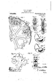
- Figure 1 is a side elevation of a wheel'provided with one form of my invention, certain of the adjustable rim portions and sprocket teeth of the wheel being omitted.
- Fig. 2 is a section taken on the line 2-2 of Fig. 1.
- Fig. 3 is a section taken on the line 33 of Fig. 1.
- Fig. .t is a detached view in side elevation of one of the members of the adjustable rim, section that forms a seat for the cable.
- Fig. 5 is an end view of the parts represented in Fig. 4.
- Fig. 6 is a detached view of one of the yielding sprocket teeth of the wheel adapted for use on a driving wheel.
- 'Fi g. 7 is a view of a tooth adapted to be used on a driven wheel.
- Fig. 8 is a view showing a slightly different form of the invention.
- Fig. 9 is a side view of a wheel embodying still another form of the invention.
- A represents a wire rope c1 strand cable
- B the contact members or 'vided with or carries a set of j ections.
- the wheel with which the cable engages comprises essentially a central portion D adapted to be secured to a shaft, radiating spokes E and a rim F, these parts being preferably formed of cast metal and of integral construction.
- the wheel is progrooved, preferably toothed, adjustable rim sections, with which the cable A engages, these adjustable rim sections being separated by gaps G.
- the rim. F of the wheel is formed, adjacent to each gap G, with outward extending peripheral lugs or projections H, H.
- the portion f of the wheel rim situated between the two projections that serve as supports for a single adjustable rim section is preferably depressed, as compared with th other parts of the wheel rim, and lies below a space I separating the pro-
- the rim is formed on its outer face with a centrally disposed longitudinal rib f for a purpose to be described.
- each lug or projection is prefa centrally disposed longitudinal rib 71/, and its inner face is curved, as represented at it, to form a seat against which rests a part of one of the adjustable cable-engaging rim sections.
- Each adjustable rim section is comprised of two parts that are duplicates of each other, one
- Figs. 4 and5 each section, considered as a whole, is of ap noximately segmental shape and is provided with a series of staggered teeth j, j, between which is the groove 7', in which the cable isadapted to lie.
- Each of the parts J is formed at its inner end with a perforated lug 2 through which passes a bolt 3, uniting these two parts.
- the perforation through the lug is preferably somewhat elongated, as indicated in Fig. 1, to allow for the necessary adjustments and relative movcmei'its of the parts to be hereafter described.
- nojcciiou 5 is longitudinally slotted, as indi'cated at 8, this slot being adapted to be brought into register with an aperture 9 formed in the projectionor lug H.
- a bolt 10 upon the screw-threaded end of which is mounted a nut 11, these two parts, the boltand nut, constituting the means for clamping the adjustable section 'J to the wheel rim.
- a screw-threaded bolt 12 which passes through the portion f of the Wheel ,r rim and as" ts end bear againstthe inner end of the? pi ojection 5, pgcferably between the flanges 7 at the bifurcated end thereof.
- the projection 13 constitutes a seat and means ofattachment for a wyielding sprocket tooth, the tooth that is 1 adapted to engage with the blocks B, B, se-' fcured to the cable.
- the parts of myad ustable cable-engaging run section are of such construction that a wheel to which they are applied may drive or be driven in both directions, so that I make provision for attaching a. yielding sprocket tooth to either end of each section as may be desired.
- Each yielding tooth has a- V-shaped portion j that is adaptedto engage with the blocks or sprockets of the cable, and a supporting shank or stem 16.
- the latter is preferably in the form of a curved plate that is adapted to enter a socket 17 formed in the part J T of the adjustable rim section.
- a yielding tooth K is employed.
- the tooth differs from the yielding tooth K only in having the stud 21 at the outer rather than at the inner end of the arcuate slot formed in the shank 16 of the tooth, the spring 20 beingreversed in its position, as will be clear from a comparison of Figs. (5 and 7. If the wheel were to be driven in the same direction as when it was the driving member, these teeth K would be mounted in the ends of the rim sections opposite those 111 which the teeth K are mounted in Fig. 1. Otherwise, the teeth K would be substituted for the teeth K. In either case, the pivot pins or bolts 19 are passed through the innermostholes 18 of the rimsections. lVhcn thus mounted thesprings ot the yielding teeth operate to force the teeth outward. (See Fig. 9.) 7
- a driving wheel or a driven wheel may be provided with yielding teeth at both ends of each of the ring sections, the wheel then being titted, without any change of the teeth, to turn in either direction.
- Fig. 9 I have shown an embodiment of my invention diii'ering in some of its details from that already described but retaining the principal features of advantage.
- the two parts J", J of the ad justable rim section are not only united to each other, but are connected by the same bolt that unites them, with a partof the wheel body, such part being for conven- L of one of the spokes of
- the construction as shown in this figure embodies the yielding teeth K which, as has been previously noted, adaptthe wheel to be driven by the cable.
- a sprocket wheel for power transnrission purposes comprising a sprockct-carrying adjustable rim section, such Section be ing formed of two parts flexibly connected together with which an endless cable engages, means for adjusting substantially radially the. rim section, and means tor holding it in place after adjustment,substantially asset t'orth.
- a wheel for power transmission pur poses having an adjustable rim section with which an endless cable engages, such adjustable section comprising two parts,mcans t'or adjusting each of the said parts substantially radiallyindependentlyof theother part, mcans tor holding each part. securely in position at'tcr adjustment, and means for connecting together the two parts ol' the rim scotion so as to pcrlnit them to move relatively to each othcr,substantially as set torth.
- a wheel for power transmission purposes consisting of a wheel body having outward extending projections formed with curved bearing t'aces /z adjustable rim sections with which a cable engages, each formed of two parts J,J, united by a con- I each part having a bearing extension with a curved face adapted to lie against a face b, means for adjusting the parts of the sections substantially radially ot' the wheel, and means tor clamping the sections against the supporting faces substantially as set forth.
- a wheel for power transmission purposes having a series of segmental rim sections, each comprising an element pivotally supported at one end and adjustable inward and outward at its other end, and means for securing said sections in adjusted position,-
- a wheel for power transmission pur- poses having a series of segmental rim'seca yielding sprocket tooth 'mounted on the.
Landscapes
- Engineering & Computer Science (AREA)
- General Engineering & Computer Science (AREA)
- Mechanical Engineering (AREA)
- Gears, Cams (AREA)
Description
W. W. WILLSON.
SBBOGKBT WHEELY APPLIUATIONIILED M11526, 1907.
Patented J1me 13,1911.
2 BHEETS-SHBET 2.
WILLIAM W. WILLSON, .OF COLUMBUS, OHIO, ASSIGNOR,
BY MESNE ASSIGNMENTS, TO
THE JEFFREY MANUFACTURING COMPANY, A CORPORATION OF OHIO.
SPROCKET-WHEEL.
Specification of Letters Patent.
season,
Patented June 13, 1911.
'Application filed April 26, 1907. Serial No. 370,383.
' v To all whom it may concern:
Be it known that I, WILLIAM W. VViLLsoN, a citizen of the United States, residing at Columbus, in the county of. Franklin and State of Ohio, have invented certain new and useful Improvements in Sprocket- Wheels, of which the following is a specification, reference being had therein to the acmpanying drawing.
' This invention relates to power transmitting apparatus in which a wire rope or cable is employed as the endless traveling element, and it consists of improvements in the wheels with which the cable engages. The advantages incidentto the use of cables, in lieu of chains for instance, have long been recognized, but they are subject to this disadvantage, that the length of the cable is liable to considerable variation, owing to the stretching thereof under conditions of severe and long continued use. Such changes of course affect the pitch of the cable, and un less the pitch of the wheel with which it engages is correspondingly changed, the cable and wheel do not work well together. It is the object of my invention to produce a wheel for use in power transmission systems wherein awire rope or cable is em ploycd, that is simple in construction, is adapted to have its pitch changed by simple mechanism and in an expeditious manner, and is provided with yielding teeth'that are arranged to engage directly with the sprocket blocks carried by the cable.
In the accompanying drawings-Figure 1 is a side elevation of a wheel'provided with one form of my invention, certain of the adjustable rim portions and sprocket teeth of the wheel being omitted. Fig. 2 is a section taken on the line 2-2 of Fig. 1. Fig. 3 is a section taken on the line 33 of Fig. 1. Fig. .t is a detached view in side elevation of one of the members of the adjustable rim, section that forms a seat for the cable. Fig. 5 is an end view of the parts represented in Fig. 4. Fig. 6 is a detached view of one of the yielding sprocket teeth of the wheel adapted for use on a driving wheel. 'Fi g. 7 is a view of a tooth adapted to be used on a driven wheel. Fig. 8 is a view showing a slightly different form of the invention. Fig. 9 is a side view of a wheel embodying still another form of the invention.
.In the drawings, A represents a wire rope c1 strand cable, B the contact members or 'vided with or carries a set of j ections.
cra'bly formed with blocks that are applied thereto, and C flights or other conveying attachments secured to the blocks B. The wheel with which the cable engages comprises essentially a central portion D adapted to be secured to a shaft, radiating spokes E and a rim F, these parts being preferably formed of cast metal and of integral construction. The wheel is progrooved, preferably toothed, adjustable rim sections, with which the cable A engages, these adjustable rim sections being separated by gaps G.
Referring particularly to the form of my invention illustrated in Fig. 1, it will beobserved that the rim. F of the wheel is formed, adjacent to each gap G, with outward extending peripheral lugs or projections H, H. The portion f of the wheel rim situated between the two projections that serve as supports for a single adjustable rim section is preferably depressed, as compared with th other parts of the wheel rim, and lies below a space I separating the pro- The rim is formed on its outer face with a centrally disposed longitudinal rib f for a purpose to be described. The outer face of each lug or projection is prefa centrally disposed longitudinal rib 71/, and its inner face is curved, as represented at it, to form a seat against which rests a part of one of the adjustable cable-engaging rim sections. Each adjustable rim section is comprised of two parts that are duplicates of each other, one
of these being represented in Figs. 4 and5, and it being designated as an entirety by J. Each section, considered as a whole, is of ap noximately segmental shape and is provided with a series of staggered teeth j, j, between which is the groove 7', in which the cable isadapted to lie. Each of the parts J is formed at its inner end with a perforated lug 2 through which passes a bolt 3, uniting these two parts. The perforation through the lug is preferably somewhat elongated, as indicated in Fig. 1, to allow for the necessary adjustments and relative movcmei'its of the parts to be hereafter described. 5 represents an inward extending projection having a curved face 6 adapted to lie against the face it of one of the projcctions or lugs H. The lower end of this projection is preferably bifurcated, as indicated at 7, so as to straddlethe rib f. The
nojcciiou 5 is longitudinally slotted, as indi'cated at 8, this slot being adapted to be brought into register with an aperture 9 formed in the projectionor lug H. In this aperture, and extending through the slot 8, is a bolt 10, upon the screw-threaded end of which is mounted a nut 11, these two parts, the boltand nut, constituting the means for clamping the adjustable section 'J to the wheel rim. In order to effect a substantially radial adjustment of the section I employ a screw-threaded bolt 12, which passes through the portion f of the Wheel ,r rim and as" ts end bear againstthe inner end of the? pi ojection 5, pgcferably between the flanges 7 at the bifurcated end thereof.
The parts formed'as thus described being assembled as indicated in Fig. 1, that is to say thetwo parts J being united by the connecting-pin or bolt 3, and the inward extending projections 1") resting against the shoulders or hearing faces h of the wheel body,.-it will be readily seen how adjustments may be effected in order to vary the pitch of thewheel. Let it be supposed that the cable has stretched so that the distance between the blocks B has increased snfli.
ciently to make-it desirable to increasethe pitch of the wheel. To accomplish this it is only necessary to loosen the nuts 11 and turn the screws 12.so as to force outward,
beyond the positions indicated in Fig. 1, the
parts of the wheel.
parts J of the adjustable cable-engaging After-the proper outward adjustments have been effected, the
sections J are tightly secured in place against the projections of the wheel body by means of the nuts 11 andbolts 10.
I prefer to form the seats h and the faces 6-of the projections that engage therewith as represented in Fig. 1, that isrurved, as, by so doing I am able to preserve the desired curvature of the cable-engaging parts of the rim under all adjustments, it'being understood that the twoparts of each adjustable rim section rock with reference to g each other upon the pivot or bolt '3 whenever an ad ustment is made.
However,
manyof the desirable features of. the invention will be preserved even should the en- 1 made plain, as indicated in Fig. 8.
is forme gaging faces of the projections H and 5 be Each I witha-n outward extension 13 projecting beyond .the bearing extension 5 and arranged tooverlie the projection H, and preferably tostraddle the rib h thereof, the
1 .end surface'ofi this projection being channeled or grooved, as indicated'at 14, for wthat purposefiThe projection 13 constitutes a seat and means ofattachment for a wyielding sprocket tooth, the tooth that is 1 adapted to engage with the blocks B, B, se-' fcured to the cable.
In my Patent No. 649,563, dated'May 15, 1900, I have described and set forth the adgart J of the adjustable rim section the section when the wheel is being driven.
The parts of myad ustable cable-engaging run section are of such construction that a wheel to which they are applied may drive or be driven in both directions, so that I make provision for attaching a. yielding sprocket tooth to either end of each section as may be desired. Each yielding tooth has a- V-shaped portion j that is adaptedto engage with the blocks or sprockets of the cable, and a supporting shank or stem 16. The latter is preferably in the form of a curved plate that is adapted to enter a socket 17 formed in the part J T of the adjustable rim section.
'lhe walls of the part J constituting the sides of the chamber 17 in which the stem of the yielding sprocket tooth lies, are perforated, asindicated at 18, 18', and through one or the other of the perforations. passes the bolt or pin 19 constituting the fulcrum about which the yielding' sproekct tooth turns or slides. A spring 20 is arranged between a centering stud 21 carried by the stem of the sprocket tooth and an abutment piece .22 mounted upon the .pin 19. This spring serves to maintain the sprocket tooth in its proper normal'position; When the tooth K is upon the'driving wheel it is situated, as already statcd, at the. forward end ofthe ad ustable rim section of the wheel,
and the pin 19 is passed through the outermost set of holes 18 ,the sprmg being then arranged. between ,t e abutment 22 and a stud 21 located near theinner en( l of the stem 16, the result being that the spring normally holds the yielding tooth close down upon the outer edge of the extension 13. This position is maintained by the yielding tooth as it is carried around by the wheel in engagement with one of the cable blocks until it reaches apoint Where the cable leaves Y the Wheel along tangential lines. Here the tooth begins to swing outward under the action of its frictional engagement with the cable block and in opposition to the tension of its spring, the pressure between the tooth and cable block gradually diminishing until th'e tooth is free to bere'tracted by its spring. Thus the cable leaves the wheel quietly and'without being subjected I to the jerking and snapping action which is characteristic of cable drives when Wheels with rigid sprocket teeth are employed.
ieuce an extension 'the wheel.
994,ses
When the wheelis to be driven by the cable, a yielding. tooth K is employed. The tooth differs from the yielding tooth K only in having the stud 21 at the outer rather than at the inner end of the arcuate slot formed in the shank 16 of the tooth, the spring 20 beingreversed in its position, as will be clear from a comparison of Figs. (5 and 7. If the wheel were to be driven in the same direction as when it was the driving member, these teeth K would be mounted in the ends of the rim sections opposite those 111 which the teeth K are mounted in Fig. 1. Otherwise, the teeth K would be substituted for the teeth K. In either case, the pivot pins or bolts 19 are passed through the innermostholes 18 of the rimsections. lVhcn thus mounted thesprings ot the yielding teeth operate to force the teeth outward. (See Fig. 9.) 7
it is obvious that either a driving wheel or a driven wheel may be provided with yielding teeth at both ends of each of the ring sections, the wheel then being titted, without any change of the teeth, to turn in either direction.
In Fig. 9 I have shown an embodiment of my invention diii'ering in some of its details from that already described but retaining the principal features of advantage. In this construction the two parts J", J of the ad justable rim section are not only united to each other, but are connected by the same bolt that unites them, with a partof the wheel body, such part being for conven- L of one of the spokes of The construction as shown in this figure embodies the yielding teeth K which, as has been previously noted, adaptthe wheel to be driven by the cable.
What i claim is:
l. A sprocket wheel for power transnrission purposes, comprising a sprockct-carrying adjustable rim section, such Section be ing formed of two parts flexibly connected together with which an endless cable engages, means for adjusting substantially radially the. rim section, and means tor holding it in place after adjustment,substantially asset t'orth.
2. A wheel for power transmission pur poses, having an adjustable rim section with which an endless cable engages, such adjustable section comprising two parts,mcans t'or adjusting each of the said parts substantially radiallyindependentlyof theother part, mcans tor holding each part. securely in position at'tcr adjustment, and means for connecting together the two parts ol' the rim scotion so as to pcrlnit them to move relatively to each othcr,substantially as set torth.
3. in a wheel l'or power transmission purposcs,'thc combination of a wheel body pro vided with outward extending projections, adjustable rim sections with I necting bolt and cable engages, each section being formed of two parts connected together so as to permit,
them to move freely independently, and each part having a bearing against aprojection carried by the body of the wheel, means for adjusting the sections substantially radially of the wheel, and means for clamping the parts of the adjustable sections to the projections of the wheel body after they have been adjusted, substantially as set forth.
4. A wheel for power transmission purposes, consisting of a wheel body having outward extending projections formed with curved bearing t'aces /z adjustable rim sections with which a cable engages, each formed of two parts J,J, united by a con- I each part having a bearing extension with a curved face adapted to lie against a face b, means for adjusting the parts of the sections substantially radially ot' the wheel, and means tor clamping the sections against the supporting faces substantially as set forth.
5. The combination with a st and cable and 'contactblocks carried thereby, of a wheel body, a rim section carried by, the wheel body with which the cable engages, the rim section at each of its ends being constructed to receive a sepa able yieldin' sprocket tooth. a separable yielding sprocket tooth arranged to be applied to either end of the said rim section of the wheel, and means for securing the said'yelding sprocket tooth in place on the said drum section, substantially as set forth.
6. The combination with an endless strand cable and contact-blocks carried thereby, of a wheel body; separable rim sections with which the cable engages fitted to the wheel body, such rim sections being constructed toreceive and support at either end a yielding sprocket tooth, means for adjusting the rim sections substantially radially of the wheel, a yielding sprocket tooth for engaging with the blocks on the cable. adapted to be applied to either end ol each of the said adjustablc rim sections, and means for securing the yielding sprockettccth to the rim sec tions, substantially as set forth.
poses, ha ring a stu'ies ot rim sections separate From each other, with which a cable is adapted to engage, each section being provided at cachcnd with a seat tor a yielding sprocket and with two sets of bolt holes Its, lb", intcrchangcable yielding sprocket teeth titted to the said seats in the rim sections. and bolts t'or uniting the viclding sprockets with the rim sections arranged to enter the bolt holes 18 or 1H, acctn'dingly as the. wheel is to be driven whccl. substantially as set forth.
8. it wheel for power transmission purposes having a series ol' segmental rim secwhichali'cll'tlless''t'ioiisf clicli 'rim section being constructed at? 7. A" wheel for power transmission purused as a driving or u 1 each 'end to receive a separable yieldingsprocket tooth, a separable yielding sprocket tooth on each of the said rim sections, and means for securing the said tooth to the rim sections, substantially as set forth.
9. A wheel for power transmission purposes having a series of segmental rim sections, each comprising an element pivotally supported at one end and adjustable inward and outward at its other end, and means for securing said sections in adjusted position,-
substantially as set forth.
10. A wheel for power transmission pur- =poses having a series of segmental rim'seca yielding sprocket tooth 'mounted on the. I
swinging end of each of the said rim elements, substantially as set forth.
In testimony whereof I aflix my signature, in presenceof two witnesses.
I WILLIAM w. WILLS ON. Witnesses: i
FRANK T. TALBOT,
' B. ALEXANDER.
Priority Applications (1)
| Application Number | Priority Date | Filing Date | Title |
|---|---|---|---|
| US37039307A US994896A (en) | 1907-04-26 | 1907-04-26 | Sprocket-wheel. |
Applications Claiming Priority (1)
| Application Number | Priority Date | Filing Date | Title |
|---|---|---|---|
| US37039307A US994896A (en) | 1907-04-26 | 1907-04-26 | Sprocket-wheel. |
Publications (1)
| Publication Number | Publication Date |
|---|---|
| US994896A true US994896A (en) | 1911-06-13 |
Family
ID=3063229
Family Applications (1)
| Application Number | Title | Priority Date | Filing Date |
|---|---|---|---|
| US37039307A Expired - Lifetime US994896A (en) | 1907-04-26 | 1907-04-26 | Sprocket-wheel. |
Country Status (1)
| Country | Link |
|---|---|
| US (1) | US994896A (en) |
Cited By (4)
| Publication number | Priority date | Publication date | Assignee | Title |
|---|---|---|---|---|
| US2561533A (en) * | 1946-05-31 | 1951-07-24 | John J Parker | Adjustable tooth gauge |
| US3230788A (en) * | 1963-08-15 | 1966-01-25 | Alvin L Henley | Adjustable circumference pulley |
| US4257519A (en) * | 1979-05-03 | 1981-03-24 | Leach John M | Frictionless entry and release sprocket |
| US5443425A (en) * | 1993-02-10 | 1995-08-22 | Stork R.M.S. B.V. | Adjustable chain wheel and components thereof |
-
1907
- 1907-04-26 US US37039307A patent/US994896A/en not_active Expired - Lifetime
Cited By (4)
| Publication number | Priority date | Publication date | Assignee | Title |
|---|---|---|---|---|
| US2561533A (en) * | 1946-05-31 | 1951-07-24 | John J Parker | Adjustable tooth gauge |
| US3230788A (en) * | 1963-08-15 | 1966-01-25 | Alvin L Henley | Adjustable circumference pulley |
| US4257519A (en) * | 1979-05-03 | 1981-03-24 | Leach John M | Frictionless entry and release sprocket |
| US5443425A (en) * | 1993-02-10 | 1995-08-22 | Stork R.M.S. B.V. | Adjustable chain wheel and components thereof |
Similar Documents
| Publication | Publication Date | Title |
|---|---|---|
| US740445A (en) | Sprocket-wheel. | |
| US717976A (en) | Sprocket-wheel for drive-chains. | |
| US1740087A (en) | Sheave structure | |
| US1244383A (en) | Sprocket-wheel. | |
| US1141869A (en) | Driving-chain for transmitting power. | |
| US810490A (en) | Sand-reel. | |
| US1493863A (en) | Sprocket wheel | |
| US691908A (en) | Axle for automobiles or other power-vehicles. | |
| US747250A (en) | Wheel or pulley. | |
| US649563A (en) | Cable sprocket-wheel. | |
| US616072A (en) | Chain and sprocket-wheel | |
| US960756A (en) | Sprocket-wheel. | |
| US1202395A (en) | Differential gear. | |
| US1027002A (en) | Driving-chain. | |
| US948385A (en) | Sprocket-wheel. | |
| US669211A (en) | Split gear-wheel. | |
| US397654A (en) | Split pulley | |
| US581689A (en) | James a | |
| US564752A (en) | Pulley | |
| US388317A (en) | Ealph john | |
| US522880A (en) | Sectional cam for ore-batteries | |
| US569216A (en) | Sprocket-wheel | |
| US466204A (en) | Wrought-metal pulley | |
| US429009A (en) | Harrison t | |
| US661021A (en) | Drive-chain and wheel therefor. |