US994270A - Massage apparatus. - Google Patents
Massage apparatus. Download PDFInfo
- Publication number
- US994270A US994270A US56757010A US1910567570A US994270A US 994270 A US994270 A US 994270A US 56757010 A US56757010 A US 56757010A US 1910567570 A US1910567570 A US 1910567570A US 994270 A US994270 A US 994270A
- Authority
- US
- United States
- Prior art keywords
- base
- hand
- tubular
- vibrator
- elastic
- Prior art date
- Legal status (The legal status is an assumption and is not a legal conclusion. Google has not performed a legal analysis and makes no representation as to the accuracy of the status listed.)
- Expired - Lifetime
Links
- 210000003813 thumb Anatomy 0.000 description 10
- 210000000707 wrist Anatomy 0.000 description 7
- 210000003811 finger Anatomy 0.000 description 4
- 210000004932 little finger Anatomy 0.000 description 4
- 239000006071 cream Substances 0.000 description 2
- 239000004519 grease Substances 0.000 description 2
- 239000002184 metal Substances 0.000 description 2
- 229920001875 Ebonite Polymers 0.000 description 1
- 241000283986 Lepus Species 0.000 description 1
- 230000004075 alteration Effects 0.000 description 1
- 230000007547 defect Effects 0.000 description 1
- 230000002950 deficient Effects 0.000 description 1
- 239000000463 material Substances 0.000 description 1
- 210000002435 tendon Anatomy 0.000 description 1
Images
Classifications
-
- A—HUMAN NECESSITIES
- A61—MEDICAL OR VETERINARY SCIENCE; HYGIENE
- A61H—PHYSICAL THERAPY APPARATUS, e.g. DEVICES FOR LOCATING OR STIMULATING REFLEX POINTS IN THE BODY; ARTIFICIAL RESPIRATION; MASSAGE; BATHING DEVICES FOR SPECIAL THERAPEUTIC OR HYGIENIC PURPOSES OR SPECIFIC PARTS OF THE BODY
- A61H23/00—Percussion or vibration massage, e.g. using supersonic vibration; Suction-vibration massage; Massage with moving diaphragms
- A61H23/02—Percussion or vibration massage, e.g. using supersonic vibration; Suction-vibration massage; Massage with moving diaphragms with electric or magnetic drive
-
- Y—GENERAL TAGGING OF NEW TECHNOLOGICAL DEVELOPMENTS; GENERAL TAGGING OF CROSS-SECTIONAL TECHNOLOGIES SPANNING OVER SEVERAL SECTIONS OF THE IPC; TECHNICAL SUBJECTS COVERED BY FORMER USPC CROSS-REFERENCE ART COLLECTIONS [XRACs] AND DIGESTS
- Y10—TECHNICAL SUBJECTS COVERED BY FORMER USPC
- Y10T—TECHNICAL SUBJECTS COVERED BY FORMER US CLASSIFICATION
- Y10T74/00—Machine element or mechanism
- Y10T74/18—Mechanical movements
- Y10T74/18544—Rotary to gyratory
- Y10T74/18552—Unbalanced weight
Definitions
- ur invention relates to improvements in massage apparatus, the object of the invention being' to provide an improved elect-ri cally operated vibrator, with improved mechanism for clampingthe same onto the hand, whereby vibrations willbe imparted to the thumb and all of thefingers and the operator may, with perfect freedom of all of his fingers, massage the face or body of the patient without any part of the apparatus or its holding' means coming,r in contact with the flesh of the patient, thereby rendering ⁇ the apparatus ⁇ a sanitary one, which the primary object of our invention.
- a further object is to provide improved means'for clampingthe vibrator on the. back of the hand, which enables the same to be easily and quickly attached and detached, and which when in position exerts an approximately equal vibrating,Y action on each of the fingers and tluunb.
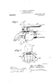
- Figure 1 is a view in side elevation illustrating our improvements in position on a hand.
- F ig. 2 is an end view of Fig'. 1.
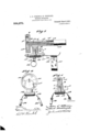
- Fig is a view in longitudinal section of the device removed.
- Fig. 4 is a view in end elevation with the cap of the vibrator rei'noved, and
- Fig. 5 is a view in vertical cross section through the pointed out in the Specification of Letters Patent.
- Our improved vibrator comprises a base 1having a tubular standard 2 thereon in the center of which an opening' 3 is provided.
- the vibrator proper comprises a circular casing;V et, integral with a tubular ex tension V a stud G, secured within the tubular standard 2 by means of a screw itL located in the opening 3 and screwed into a threaded socket 7 in the lower end of stud 6.
- the circular casing 4 is externally screwthreaded and is closed by cap 8, having an internally screw-threaded annular flange 9 screwed onto the casing 4.
- the tubular extension' has a tubular bushing ⁇ 10, in which a tubular shaft 11 is mounted to turn, and on this tubular shaft 11, within the casing 4, a segmental iveight 12 is provided, so that when the shaft is rapidly revolved, the weight will cause a vibration of the mechanism, as is well understood.
- Vhile of course, our improved mechanism is in no wise limited to the particular means for driving the same, we preferably employ a iiexible shaft 13 inclosed in a easing 14, screwed onto a threaded extension 15 on the end of tube with the shaft 13 projecting into and tightly engagingl the tubular shaft 11.
- This shaft 13 is preferably driven by an electric motor, but may of course, be driven by any means.
- an elongated metal plate 16 is secured by screws 17, and lies longitudinally of the back of the hand and extends from a point adjacentth knuckles to the wrist,.as illustrated more clearly in Fig. 1.
- a strip of elastic 19 is positioned and is provided at its ends with rings Q0, and 21, respectively, ring 2O being preferably smaller than ring 21 and adapted to receive the little finger of the hand, while the larger ring 21 receives the thumb.
- the rear end of plate 16 is slotted to recelve a band of elasticQQ, which is provided with a suitable catch 23, so as to secure the same around the wristy of the user.
- the rings Q0, and 2l are preteralily ot metal, hardrubber, or some other material, which will not absorb any moisture, and as tl'iey are the. only parts ot the attachment which could by any possibilitycontact with the flesh, they can be maintained perfectly clean, however, in ordinary massage these rings would never touch the patient, and our attachn'ient may be used over and over again without becoming soiled by ⁇ -any sort of grease or cream that may be used.
- a novice ol the character described comprising a ⁇ base, a vibrator on the base, said base adapted to be positioned on the back of the hand, a wrist strap at one end of said base, transversely projecting elastic connected with said base and rings on the 'tree ends olf said elastic, one ring adapted to be positioned on the little finger and the other on the thumb ot the operator, said vibrator solely secured to the baci( of the vhand by said wrist strap and said thuinb and little finger rings, sul'istantially as described.
- a device of the character described comprising a base, a tubular standard on the base, a circular vibrator easing, a removable cap on said casing'. a tubular extension ou said casing, a stud on said tubular evlension secured in ,said slainlard, a tubular sha l ⁇ t in said extension, a segmental weight on the cnd oi, said sha't't in the easing', nnans tor transmitting motion to said shaft, and :means tor securing' said standard on the haelt ot 'the hand ot the operator,l said means romprising a wrist. band and an elastic strap provided with rings to receive the thumb and little linger, said vibrator solely secured to the back ot the hand by said wrist .strap and said thumb and .little tinger rings, substanliall)Y as described.
- a device of the character described comprising a base, a tubular standard on the base, a circular vibrator casing, a removable ⁇ cap on said casing, a tubular extension on said casing, a stud on said tubular erdension, secured in said standard, a tubular shaft in said extension, a segmental weight ou the end ot said shat't in the. easing'. means For transmitting motion to said shaft, a plate secured to the bottoni of said base, a.
Landscapes
- Health & Medical Sciences (AREA)
- Epidemiology (AREA)
- Pain & Pain Management (AREA)
- Physical Education & Sports Medicine (AREA)
- Rehabilitation Therapy (AREA)
- Life Sciences & Earth Sciences (AREA)
- Animal Behavior & Ethology (AREA)
- General Health & Medical Sciences (AREA)
- Public Health (AREA)
- Veterinary Medicine (AREA)
- Percussion Or Vibration Massage (AREA)
Description
J. P. OBRIEN & H.STODDARD. MASSAGE APPARATUS. APPLIOATION HLED JUNE 18, 1910.
. Patented June 6,1911] 2 SHEETS-SHEET 1.
gud/wicca! 170211 Z 012212, aff fad J. P. BRIEN & H. STODDABD. MASSAGE APYARATUS. APPLICATION FILED 3mm 18,1910.
994,270,- Pamd nine 6,1911. z SHEETS-SHEET 2.
Nag/1f aq if A5.
TTED STATES PATEN T FFICE.
JOHN P. OBRIEN AND HART STODDARD, OF PHILADELPHIA, PENNSYLVANIA; SAID STODDARD ASSIGNOR TO SAID OBRIEN.
MASSAGE APPARATUS.
To all whom it may concern.' l
lie it known thatwe, JOHN 1. Olhincn,l and Haar S'ronnilm; citizens of the United States, residing` at Philadelphia, county of `Philadelphia, and State of Pennsylvania, have invented certain new and useful 1mprovements in Massage Apparatus, of which the following is a specification.
(ur invention relates to improvements in massage apparatus, the object of the invention being' to provide an improved elect-ri cally operated vibrator, with improved mechanism for clampingthe same onto the hand, whereby vibrations willbe imparted to the thumb and all of thefingers and the operator may, with perfect freedom of all of his fingers, massage the face or body of the patient without any part of the apparatus or its holding' means coming,r in contact with the flesh of the patient, thereby rendering` the apparatus `a sanitary one, which the primary object of our invention.
A further object is to provide improved means'for clampingthe vibrator on the. back of the hand, which enables the same to be easily and quickly attached and detached, and which when in position exerts an approximately equal vibrating,Y action on each of the fingers and tluunb.
lleretotore, many devices have been devised for imparting to the hand vibrations, so that the hand may be effectually used in massaging. These devices have been defective, either for the reason that they do not impart to all of the fingers and thumb the necessary vibrations, or thatthey are so connected with the hand that they quickly become unsanitary and unfit for use. Our invention was devised with a view to overcoming these defects, and will now be described in detail. vVith these and other 'objects in view, the invention consists in certain novel features of constrlnftion and combinationsand arrangements of parts.v as will be more fully hereinafter described and claims.
In the accompanying drawings: Figure 1, is a view in side elevation illustrating our improvements in position on a hand. F ig. 2, is an end view of Fig'. 1. Fig, isa view in longitudinal section of the device removed. Fig. 4, is a view in end elevation with the cap of the vibrator rei'noved, and Fig. 5, is a view in vertical cross section through the pointed out in the Specification of Letters Patent.
l Application .ned June 1s, 1910.
Patented June 6, '1911. serial No. 567,570.
g pivotal connection between the vibrator and its mount.
Our improved vibrator comprises a base 1having a tubular standard 2 thereon in the center of which an opening' 3 is provided. The vibrator proper comprises a circular casing;V et, integral with a tubular ex tension V a stud G, secured within the tubular standard 2 by means of a screw itL located in the opening 3 and screwed into a threaded socket 7 in the lower end of stud 6.
The circular casing 4 is externally screwthreaded and is closed by cap 8, having an internally screw-threaded annular flange 9 screwed onto the casing 4. The tubular extension' has a tubular bushing` 10, in which a tubular shaft 11 is mounted to turn, and on this tubular shaft 11, within the casing 4, a segmental iveight 12 is provided, so that when the shaft is rapidly revolved, the weight will cause a vibration of the mechanism, as is well understood.
Vhile, of course, our improved mechanism is in no wise limited to the particular means for driving the same, we preferably employ a iiexible shaft 13 inclosed in a easing 14, screwed onto a threaded extension 15 on the end of tube with the shaft 13 projecting into and tightly engagingl the tubular shaft 11. This shaft 13 is preferably driven by an electric motor, but may of course, be driven by any means.
To the lower face of base 1, an elongated metal plate 16 is secured by screws 17, and lies longitudinally of the back of the hand and extends from a point adjacentth knuckles to the wrist,.as illustrated more clearly in Fig. 1.
A cushion 18, preferably of rubber, is positioned around the plate 16 below base 1, and is adapted to cushion the device ont-he back of the hand. Between this cushion 1S, and the base 1, a strip of elastic 19 is positioned and is provided at its ends With rings Q0, and 21, respectively, ring 2O being preferably smaller than ring 21 and adapted to receive the little finger of the hand, while the larger ring 21 receives the thumb. The rear end of plate 16 is slotted to recelve a band of elasticQQ, which is provided with a suitable catch 23, so as to secure the same around the wristy of the user.
o, and the latter is provided witlr .It will be noted that with ourimproved attachment, the cushion 18 will engage the three central tendons in the back of the hand, While thethumh and little linger are 'directly connected with the attachment by means ol the `elastic 191 vibrations ot the mitted to the thumb and all et the lingers alike, so that the operator may manipulate his hand over the Hash ot the patient, and -t'rom each and every one of his fingers the :vibrations will be imparted to the flesh. Furthermore, it will be noted that in doing so, no part ot the attachment comes into Contact with the flesh of the patient, for in massaging of this character, especiallj)7 where greases and creams are used, it is very essential that no party of the apparatus should contact 'with the flesh of the patient, for if it should, it would soon become impregnated iv'th dirt and grease, and the device would be absoluteli7 unsanitary and unfit for use.
The rings Q0, and 2l, are preteralily ot metal, hardrubber, or some other material, which will not absorb any moisture, and as tl'iey are the. only parts ot the attachment which could by any possibilitycontact with the flesh, they can be maintained perfectly clean, however, in ordinary massage these rings would never touch the patient, and our attachn'ient may be used over and over again without becoming soiled by `-any sort of grease or cream that may be used.
Various slight changes might be made in the general form and arrangement ot parts described Without departing from our invention, and hence we do not limitourselves to the precise. details set forth, but consider ourselves at liberty to make such changes and alterations as fairly tall within the spirit and scope ot the appended claims.
llavingv thus described our invention, what we claim as new and desire to secure by Letters patent is:
l. A novice ol the character described, comprising a` base, a vibrator on the base, said base adapted to be positioned on the back of the hand, a wrist strap at one end of said base, transversely projecting elastic connected with said base and rings on the 'tree ends olf said elastic, one ring adapted to be positioned on the little finger and the other on the thumb ot the operator, said vibrator solely secured to the baci( of the vhand by said wrist strap and said thuinb and little finger rings, sul'istantially as described.
9. device ot the character described, comprisin,Y a base, a vibra-tor having rotary Therefore, the
attachment 'are trans? mountingron the hase, a plate secured to the under face ot' the base and adapted to extend longitudinally of the back of a hand, a cushion below said plate, an elastic band connected to said base, rings on the tree ends of said elastic band adapted to be positioned on the little linger and thumb ot' the operator, and an elastic Wrist band connected to said plate and Secured around the u'rist olf the operator, said vibnxtorlsolelj7 secured to the baekot' the hand by said elastic wrist band and said thumb and.little finger. rings, substantially as described,
3. A device of the character described, comprising a base, a tubular standard on the base, a circular vibrator easing, a removable cap on said casing'. a tubular extension ou said casing, a stud on said tubular evlension secured in ,said slainlard, a tubular sha l`t in said extension, a segmental weight on the cnd oi, said sha't't in the easing', nnans tor transmitting motion to said shaft, and :means tor securing' said standard on the haelt ot 'the hand ot the operator,l said means romprising a wrist. band and an elastic strap provided with rings to receive the thumb and little linger, said vibrator solely secured to the back ot the hand by said wrist .strap and said thumb and .little tinger rings, substanliall)Y as described.
Ll. A device of the character described, comprising a base, a tubular standard on the base, a circular vibrator casing, a removable `cap on said casing, a tubular extension on said casing, a stud on said tubular erdension, secured in said standard, a tubular shaft in said extension, a segmental weight ou the end ot said shat't in the. easing'. means For transmitting motion to said shaft, a plate secured to the bottoni of said base, a. cushion on said plat i adapted lo be positioned on the back ot' thc hand, an elastic band positioned between said plate and said base, rings ou the tree ends oll .said elastic baud adapted lo engage over the little linger and thumb oll the operator, and au elastic baud connected lo said plate and adapted lo be positioned around the u'rist ol` the operator, subslauw lially as described.
lu testimoniy whereof ivo have signed our naines to this sperilicalion in the presence ot two subscribing \\'ituossos.
JOHN l). (Vllt ll,\lt'l` S'l`()l)l)A Wil nesses: l
ll, ll. Karmann, (l. ll. lo'r'l'S.
un'. tuo`
Priority Applications (1)
| Application Number | Priority Date | Filing Date | Title |
|---|---|---|---|
| US56757010A US994270A (en) | 1910-06-18 | 1910-06-18 | Massage apparatus. |
Applications Claiming Priority (1)
| Application Number | Priority Date | Filing Date | Title |
|---|---|---|---|
| US56757010A US994270A (en) | 1910-06-18 | 1910-06-18 | Massage apparatus. |
Publications (1)
| Publication Number | Publication Date |
|---|---|
| US994270A true US994270A (en) | 1911-06-06 |
Family
ID=3062603
Family Applications (1)
| Application Number | Title | Priority Date | Filing Date |
|---|---|---|---|
| US56757010A Expired - Lifetime US994270A (en) | 1910-06-18 | 1910-06-18 | Massage apparatus. |
Country Status (1)
| Country | Link |
|---|---|
| US (1) | US994270A (en) |
Cited By (6)
| Publication number | Priority date | Publication date | Assignee | Title |
|---|---|---|---|---|
| US2703571A (en) * | 1953-11-13 | 1955-03-08 | Thomas Jack | Massaging machine attachment |
| US2829527A (en) * | 1956-05-10 | 1958-04-08 | Burritt G Fleming | Power operated vibrators |
| US2918055A (en) * | 1957-03-11 | 1959-12-22 | Henry E Meltzer | Hand massager |
| US3063443A (en) * | 1959-12-03 | 1962-11-13 | Wahl Clipper Corp | Base assembly for massage device |
| US6267736B1 (en) | 1997-08-19 | 2001-07-31 | Wahl Clipper Corporation | Articulated multi-directional hand-held massage apparatus |
| US20130218058A1 (en) * | 2010-10-29 | 2013-08-22 | Bosco System Lab S.P.A. | Apparatus for transmitting localised vibrations, in particular to muscles of a user |
-
1910
- 1910-06-18 US US56757010A patent/US994270A/en not_active Expired - Lifetime
Cited By (6)
| Publication number | Priority date | Publication date | Assignee | Title |
|---|---|---|---|---|
| US2703571A (en) * | 1953-11-13 | 1955-03-08 | Thomas Jack | Massaging machine attachment |
| US2829527A (en) * | 1956-05-10 | 1958-04-08 | Burritt G Fleming | Power operated vibrators |
| US2918055A (en) * | 1957-03-11 | 1959-12-22 | Henry E Meltzer | Hand massager |
| US3063443A (en) * | 1959-12-03 | 1962-11-13 | Wahl Clipper Corp | Base assembly for massage device |
| US6267736B1 (en) | 1997-08-19 | 2001-07-31 | Wahl Clipper Corporation | Articulated multi-directional hand-held massage apparatus |
| US20130218058A1 (en) * | 2010-10-29 | 2013-08-22 | Bosco System Lab S.P.A. | Apparatus for transmitting localised vibrations, in particular to muscles of a user |
Similar Documents
| Publication | Publication Date | Title |
|---|---|---|
| US2181282A (en) | Vibrator | |
| US2648787A (en) | Motor-driven toothbrush | |
| US1520908A (en) | Brush for cleaning nasal passages | |
| US2113444A (en) | Vibrating motor | |
| US1822631A (en) | Revolving toothbrush and nail polisher | |
| US1658801A (en) | Nasal-cleaning device | |
| US2250975A (en) | Mechanical brushing device | |
| US859424A (en) | Vibrator for massage purposes. | |
| US2018046A (en) | Vibrator | |
| US505745A (en) | Wrist and finger exercising apparatus | |
| US1134047A (en) | Cam-movement for jig-polishers. | |
| US2034758A (en) | Power driven rotary kneader and massager | |
| US807299A (en) | Vibrator for medical use. | |
| US2054849A (en) | Massage appliance or the like | |
| US1622182A (en) | Meat-block cleaner | |
| US855342A (en) | Movement-cure device. | |
| US920814A (en) | Apparatus for dermal treatment. | |
| US761856A (en) | Glove-form. | |
| US735713A (en) | Automatic screen-brush. | |
| US690166A (en) | Finger-manipulator. | |
| US1774402A (en) | Exercising machine | |
| US1481891A (en) | Rotary toothbrush | |
| US1371044A (en) | Massage-tool | |
| US2533807A (en) | Oscillating rack actuated drive | |
| US1270137A (en) | Pasteurizer-coil brush. |