US9942072B1 - Communications device with adaptive demodulator for PSK and FSK modulations and related methods - Google Patents
Communications device with adaptive demodulator for PSK and FSK modulations and related methods Download PDFInfo
- Publication number
- US9942072B1 US9942072B1 US15/417,450 US201715417450A US9942072B1 US 9942072 B1 US9942072 B1 US 9942072B1 US 201715417450 A US201715417450 A US 201715417450A US 9942072 B1 US9942072 B1 US 9942072B1
- Authority
- US
- United States
- Prior art keywords
- modulation type
- received signal
- psk
- amplitude information
- classify
- Prior art date
- Legal status (The legal status is an assumption and is not a legal conclusion. Google has not performed a legal analysis and makes no representation as to the accuracy of the status listed.)
- Active
Links
Images


Classifications
-
- H—ELECTRICITY
- H04—ELECTRIC COMMUNICATION TECHNIQUE
- H04L—TRANSMISSION OF DIGITAL INFORMATION, e.g. TELEGRAPHIC COMMUNICATION
- H04L27/00—Modulated-carrier systems
- H04L27/18—Phase-modulated carrier systems, i.e. using phase-shift keying
- H04L27/22—Demodulator circuits; Receiver circuits
-
- H—ELECTRICITY
- H04—ELECTRIC COMMUNICATION TECHNIQUE
- H04L—TRANSMISSION OF DIGITAL INFORMATION, e.g. TELEGRAPHIC COMMUNICATION
- H04L27/00—Modulated-carrier systems
- H04L27/10—Frequency-modulated carrier systems, i.e. using frequency-shift keying
- H04L27/14—Demodulator circuits; Receiver circuits
Definitions
- the present invention relates to the field of wireless communications, and, more particularly, to demodulation of signals and related methods.
- the data to be transmitted which at its most basic level comprises 1s and 0s, may be encoded into a modulation waveform.
- a transmitter device changes the transmitted signal based upon the modulation waveform.
- a typical modulation waveform may include M-ary frequency-shift keying (M-FSK), which is a frequency modulation scheme transmitting digital information through discrete frequency changes of a carrier wave.
- M-FSK frequency-shift keying
- a rudimentary example of the M-FSK modulation waveform is the binary FSK (BFSK or 2-FSK), which includes using a single pair of discrete frequencies to transmit digital data.
- Other modulation waveforms may include, for example, Gaussian minimum shift keying (GMSK), M-ary pulse amplitude modulation (M-PAM), M-ary phase shift keying (M-PSK), and M-ary quadrature amplitude modulation (M-QAM).
- GMSK Gaussian minimum shift keying
- M-PAM M-ary pulse amplitude modulation
- M-PSK M-ary phase shift keying
- M-QAM M-ary quadrature amplitude modulation
- the choice of the modulation waveform may depend on the performance demands of the system, for example, throughput and the type of data services being transmitted. For example, some modulation waveforms may be better suited for transmitting voice services rather than pure data services.
- a wireless communications device may include a wireless receiver, and an adaptive demodulator coupled to the wireless receiver.
- the adaptive demodulator may be configured to apply first and second bandpass filters to amplitude information of a received signal at first and second frequency bands, respectively, and classify the received signal as one of a first phase-shift keying (PSK) modulation type, a second PSK modulation type, and a third frequency-shift keying (FSK) modulation type based upon whether a tone exists in the amplitude information of the received signal in at least one of the first and second frequency bands.
- PSK phase-shift keying
- FSK frequency-shift keying
- the adaptive demodulator may be configured to adjust at least one demodulating parameter based upon a classified modulation type of the received signal.
- the adaptive demodulator may be configured to classify the received signal as the first PSK modulation type when the tone exists at the first frequency band, classify the received signal as the second PSK modulation type when the tone exists at the second frequency band, and classify the received signal as the third FSK modulation type when the tone does not exist at both of the first frequency band and the second frequency band.
- the adaptive demodulator may be configured to determine whether the tone exists in the amplitude information of the received signal at the first and second frequency bands by comparing the amplitude information of the received signal at the first and second frequency bands to a threshold.
- the first and second PSK modulation types may comprise quadrature phase shift keying (QPSK) modulation types at different symbol rates
- the third FSK modulation type may comprise a compatible 4-level frequency (C4FM) modulation type.
- the at least one demodulating parameter may comprise a demodulation filter bandwidth, or a phase difference calculation over a symbol, for example.
- the adaptive demodulator may be configured to determine a plurality of phase difference values when the received signal is the third FSK modulation type, the plurality of phase difference values being integrated over a symbol interval.
- the adaptive demodulator may be configured to determine a single phase difference value at a symbol rate when the received signal is one of the first and second PSK modulation types.
- the adaptive demodulator may be configured to apply the first and second bandpass filters, and determine whether the tone exists in the amplitude information of the received signal at the first and second frequency bands using first and second parallel processing paths.
- the wireless communications device may include a housing, an antenna carried by the housing, a wireless receiver carried by the housing and coupled to the antenna, and an adaptive demodulator carried by the housing and coupled to the wireless receiver.
- the adaptive demodulator may be configured to apply first and second bandpass filters to amplitude information of a received signal at first and second frequency bands, respectively, and classify the received signal as one of a first PSK modulation type, a second PSK modulation type, and a third FSK modulation type based upon whether a tone exists in the amplitude information of the received signal in at least one of the first and second frequency bands.
- the adaptive demodulator may be configured to adjust at least one demodulating parameter based upon a classified modulation type of the received signal.
- the wireless communication system may include a transmitter device configured to transmit a signal of unknown modulation type selected from one of a first PSK modulation type, a second PSK modulation type, and a third FSK modulation type.
- the wireless communication system may comprise a receiver device comprising a wireless receiver, and an adaptive demodulator coupled to the wireless receiver and configured to apply first and second bandpass filters to amplitude information of the signal at first and second frequency bands, respectively, and classify the signal as one of a first PSK modulation type, a second PSK modulation type, and a third FSK modulation type based upon whether a tone exists in the amplitude information of the signal in at least one of the first and second frequency bands.
- the adaptive demodulator may be configured to adjust at least one demodulating parameter based upon a classified modulation type of the signal.
- the method may include operating an adaptive demodulator to apply first and second bandpass filters to amplitude information of a received signal at first and second frequency bands, respectively, and operating the adaptive demodulator to classify the received signal as one of a first PSK modulation type, a second PSK modulation type, and a third FSK modulation type based upon whether a tone exists in the amplitude information of the received signal in at least one of the first and second frequency bands.
- the method may include operating the adaptive demodulator to adjust at least one demodulating parameter based upon a classified modulation type of the received signal.
- FIG. 1 is a schematic diagram of a wireless communication system, according to the present disclosure.
- FIG. 2 is a diagram of bit error rate with varying bandwidth with C4FM and wide eye pattern-compatible quadrature phase shift keying (WCQPSK) modulation waveforms.
- WCQPSK quadrature phase shift keying
- FIGS. 3A and 3B are diagrams of bit error rate difference for static and faded signals at 30 Hz Doppler frequency, respectively, for the C4FM modulation waveform.
- FIG. 4 is a flowchart illustrating operation of the adaptive demodulator of the wireless communication system of FIG. 1 .
- FIG. 5 is a schematic diagram of the adaptive demodulator of the wireless communication system of FIG. 1 .
- FIG. 6 is a diagram of modulation detector output in the wireless communication system of FIG. 1 .
- FIGS. 7A-7B are constellation diagrams for 9.6 kbps C4FM and 9.6 kbps WCQPSK, respectively, in the wireless communication system of FIG. 1 .
- FIGS. 8A-8B are a spectrum diagram and a constellation diagram, respectively for 9.6 kbps C4FM, in the wireless communication system of FIG. 1 .
- FIGS. 9A-9B are a spectrum diagram and a constellation diagram, respectively for 9.6 kbps WCQPSK, in the wireless communication system of FIG. 1 .
- FIGS. 10A-10B are a spectrum diagram and a constellation diagram, respectively for 12 kbps Harmonized Differential Quadrature Phase Shift Keying (HDQPSK).
- HDQPSK Harmonized Differential Quadrature Phase Shift Keying
- FIGS. 11A-11C are spectrum diagrams for the C4FM, WCQPSK, and HDQPSK modulation waveforms, respectively, in the wireless communication system of FIG. 1 .
- FIGS. 12A-12B are soft symbol decision diagrams with integration of multiple phase differences over a symbol period calculations and single phase difference calculations over a symbol period, respectively, with a faded weak signal in the wireless communication system of FIG. 1 .
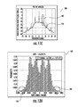
- FIGS. 13A-13B are soft symbol decision diagrams with integration of multiple phase differences over a symbol period calculations and single phase difference calculations over a symbol period, respectively, with a signal at the coverage threshold in the wireless communication system of FIG. 1 .
- the wireless communication system 20 includes a transmitter device 21 comprising a wireless transmitter 22 , and an antenna 23 coupled thereto and configured to transmit a signal of unknown modulation type selected from one of a first PSK modulation type, a second PSK modulation type, and a third FSK modulation type.
- the transmitter device 21 illustratively includes a wireless receiver 56 , and an antenna 57 coupled thereto for receiving signals.
- the wireless communication system 20 may deploy the Project 25 (P25 or Association of Public-Safety Communications Officials-International (APCO)-25) digital radio communication standard.
- the first and second PSK modulation types may comprise differential quadrature phase shift keying (DQPSK) modulation types at different symbol rates (e.g. ⁇ /4 DQPSK/WCQPSK at 9.6 kbps and ⁇ /4 DQPSK/HDQPSK at 12 kbps), and the third FSK modulation type may comprise a compatible 4-level frequency (C4FM) modulation type at 9.6 kbps.
- the received signal is carried within the control channel of the operational spectrum of the wireless communication system 20 .
- other modulation types could be used in other embodiments.
- diagrams 80 , 82 show the frequency spectrum 81 and the constellation diagram 83 , respectively for the C4FM modulation type at 9.6 kbps.
- Diagrams 84 , 86 show the frequency spectrum 85 and the constellation diagram 87 , respectively for the WCQPSK modulation type at 9.6 kbps.
- Diagrams 88 , 90 show the frequency spectrum 89 and the constellation diagram 91 , respectively for the HDQPSK modulation type at 12 kbps.
- the wireless communication system 20 includes a receiver device 24 comprising a wireless receiver 25 , an adaptive demodulator 26 coupled to the wireless receiver, and an antenna 27 coupled to the wireless receiver.
- the receiver device 24 illustratively includes a wireless transmitter 29 , and an antenna 39 coupled thereto for transmitting signals.
- the receiver device 24 illustratively includes a housing 28 carrying the antennas 27 , 39 , the wireless receiver 25 , the adaptive demodulator 26 , the wireless transmitter 29 , and any other necessary circuitry.
- the housing 28 may comprise a ruggedized portable housing (e.g. rubber or plastic material), but in other embodiments, the housing may be more suited for a fixed placement (e.g. rigid metallic box).
- wireless transmitters 22 , 29 and the wireless receivers 56 , 25 are depicted as separate blocks for illustrative purposes, it should be appreciated that these components may be part of integrated transceiver circuits. Similarly, separate antennas 23 , 57 , 27 , 39 are shown for illustrative purposes, the skilled person will appreciate that a common transmit-receive antenna could be used. Also, the adaptive demodulator 26 may comprise a general purpose processing device in some embodiments, or an application-specific integrated circuit (ASIC) in other embodiments.
- ASIC application-specific integrated circuit
- the receiver device 24 may demodulate the received signal without a priori knowledge of the modulation type (i.e. the modulation waveform).
- the receiver device 24 may use a single demodulation process (e.g. generic linear demodulation process) for the received signal regardless of the modulation type.
- the demodulation is usually suboptimal since the demodulation is generically derived to be functional for more than one modulation type. Indeed, in applications where the received signal may use modulation types of varying symbol rates, the generic demodulation may not be possible.
- diagram 30 shows the bit error rate (BER) plots 31 , 32 for C4FM and WCQPSK, respectively, as a bandwidth for the demodulation filter (i.e. the In-phase/Quadrature filter) is varied.
- the modulation types have different optimal bandwidths.
- diagrams 33 , 36 shown the BER plots for the C4FM modulation type with linear processing 34 , 37 and optimized C4FM demodulation processing 35 , 38 . As shown, when the generic linear processing is used, the BER is approximately 1.5 dB greater.
- the adaptive demodulator 26 is configured to apply first and second bandpass filters to amplitude information (i.e. absolute value of the signal) of the signal at first and second frequency bands, respectively, and classify the signal (i.e. a received signal) as one of a first PSK modulation type, a second PSK modulation type, and a third FSK modulation type based upon whether a tone exists in the amplitude information of the signal in at least one of the first and second frequency bands, i.e. either one of the first and second frequency bands (Diagram 55 , and Blocks 50 - 54 ).
- the adaptive demodulator 26 illustratively includes an initial absolute value block 41 ingesting the amplitude information of the received signal and splitting the received signal between first and second parallel processing paths.
- the first processing path illustratively includes the first bandpass filter 42 (e.g. the illustrated 100 Hz tone filter centered at 4.8 kHz), a first absolute value block 43 downstream from the first bandpass filter, a first low pass filter 44 downstream from the first bandpass filter, and a first threshold comparison block 45 downstream from the first low pass filter.
- the second processing path illustratively includes the second bandpass filter 46 (e.g.
- each of the first and second processing paths has a specified bandwidth configured respectively for the first and second PSK modulation types.
- the adaptive demodulator 26 is configured to classify the received signal as the first PSK modulation type (i.e. ⁇ /4 DQPSK/WCQPSK at 9.6 kbps) when the tone exists at the amplitude information of the first frequency band (4.8 kHz ⁇ 50 Hz).
- the adaptive demodulator 26 is configured to classify the received signal as the second PSK modulation type (i.e. ⁇ /4 DQPSK/HDQPSK at 12 kbps) when the tone exists at the amplitude information of the second frequency band (6 kHz ⁇ 50 Hz), and classify the received signal as the third FSK modulation type (i.e.
- the adaptive demodulator 26 is configured to determine whether the tone exists in the amplitude information of the received signal at the first and second frequency bands by comparing the amplitude information of the received signal at the first and second frequency bands to a threshold via the first and second comparison blocks 45 , 49 .
- the third FSK modulation type has a frequency spectrum 96 without tones.
- the frequency spectrums 98 , 101 of the first and second PSK modulation types have detectable tones 99 , 102 .
- the threshold comparison processing is illustrated.
- the threshold 66 is at amplitude value 0.1.
- Curves 61 , 62 depict the WCQPSK4p8 and HDQPSK6 modulation types, which exceed the threshold 66 .
- Curves 63 , 64 , 65 depict the WCQPSK6, C4FM4p8, and HDQPSK4p8 modulation types, which do not exceed the threshold 66 .
- the adaptive demodulator 26 is configured to adjust at least one demodulating parameter based upon a classified modulation type of the received signal. In other words, the adaptive demodulator 26 optimizes the demodulation processing based upon the detected modulation type.
- At least one demodulating parameter may comprise a demodulation filter bandwidth.
- the demodulation filter bandwidth may be optimized based upon the data in diagram 30 ( FIG. 2 ).
- the at least one demodulating parameter may comprise a phase difference calculation over a symbol.
- diagram 70 which shows the constellation diagram 71 of C4FM at 9.6 kbps
- the adaptive demodulator 26 is configured to determine a plurality of phase difference values 72 a - 72 g when the received signal is the third FSK modulation type, the plurality of phase difference values being integrated over a symbol interval. This may help to prevent 2 n phase wraps in weak signal (e.g. signal has fade or noise) environments.
- the adaptive demodulator 26 is configured to determine a single phase difference value 75 a - 75 b at a symbol rate when the received signal is one of the first and second PSK modulation types (i.e. the linear modulations).
- the adaptive demodulator 26 is configured to sample at peak energy points of the received signal.
- the wireless communications device 24 includes a housing 28 , an antenna 27 carried by the housing, a wireless receiver 25 carried by the housing and coupled to the antenna, and an adaptive demodulator 26 carried by the housing and coupled to the wireless receiver.
- the adaptive demodulator 26 is configured to apply first and second bandpass filters to amplitude information of a received signal at first and second frequency bands, respectively, and classify the received signal as one of a first PSK modulation type, a second PSK modulation type, and a third FSK modulation type based upon whether a tone exists in the amplitude information of the received signal in at least one of (i.e. either one of the first and second frequency bands) the first and second frequency bands.
- the adaptive demodulator 26 is configured to adjust at least one demodulating parameter based upon a classified modulation type of the received signal.
- the method includes operating an adaptive demodulator 26 to apply first and second bandpass filters to amplitude information of a received signal at first and second frequency bands, respectively, and operating the adaptive demodulator to classify the received signal as one of a first PSK modulation type, a second PSK modulation type, and a third FSK modulation type based upon whether a tone exists in the amplitude information of the received signal in at least one of the first and second frequency bands (i.e. either one of the first and second frequency bands).
- the method includes operating the adaptive demodulator 26 to adjust at least one demodulating parameter based upon a classified modulation type of the received signal.
- diagram 103 shows the BER when the adaptive demodulator 26 is configured to integrate multiple phase differences over a symbol period.
- the diagram 103 illustratively includes portions 104 - 105 that show the received signal demodulated correctly when integrating multiple phase differences, i.e. a BER of approximately 13.7%.
- Diagram 110 shows the received signal demodulated when calculating a single phase difference over the symbol period integrating multiple phase differences, i.e. a BER of approximately 15.6%.
- diagram 115 shows the BER when the adaptive demodulator 26 is configured to integrate multiple phase differences over a symbol period.
- the diagram 115 illustratively includes portions 116 - 117 that show the received signal demodulated correctly when integrating multiple phase differences, i.e. a BER of approximately 2.16%.
- Diagram 118 shows the received signal demodulated when calculating a single phase difference over the symbol period integrating multiple phase differences, i.e. a BER of approximately 2.42%.
- the wireless communication system 20 may provide for a simple tone detection method for determining modulation type and symbol rate. Also, the wireless communication system 20 may adapt filter bandwidth based on modulation type to improve radio receive sensitivity, and adapt the phase difference demodulator method using one difference over a symbol for ⁇ /4 DQPSK modulations or integrating several phase differences over a symbol for C4FM modulation to increase radio performance. Moreover, the wireless communication system 20 deploys an algorithm that may improve existing P25 Phase 1&2 terminal performance for allowing devices to operate in a P25 conventional simulcast system, and may enhance radio sensitivity, which will improve voice quality and enhance overall user experience.
Landscapes
- Engineering & Computer Science (AREA)
- Computer Networks & Wireless Communication (AREA)
- Signal Processing (AREA)
- Digital Transmission Methods That Use Modulated Carrier Waves (AREA)
Abstract
Description
Claims (23)
Priority Applications (1)
| Application Number | Priority Date | Filing Date | Title |
|---|---|---|---|
| US15/417,450 US9942072B1 (en) | 2017-01-27 | 2017-01-27 | Communications device with adaptive demodulator for PSK and FSK modulations and related methods |
Applications Claiming Priority (1)
| Application Number | Priority Date | Filing Date | Title |
|---|---|---|---|
| US15/417,450 US9942072B1 (en) | 2017-01-27 | 2017-01-27 | Communications device with adaptive demodulator for PSK and FSK modulations and related methods |
Publications (1)
| Publication Number | Publication Date |
|---|---|
| US9942072B1 true US9942072B1 (en) | 2018-04-10 |
Family
ID=61801594
Family Applications (1)
| Application Number | Title | Priority Date | Filing Date |
|---|---|---|---|
| US15/417,450 Active US9942072B1 (en) | 2017-01-27 | 2017-01-27 | Communications device with adaptive demodulator for PSK and FSK modulations and related methods |
Country Status (1)
| Country | Link |
|---|---|
| US (1) | US9942072B1 (en) |
Citations (7)
| Publication number | Priority date | Publication date | Assignee | Title |
|---|---|---|---|---|
| US20030090367A1 (en) * | 2000-12-20 | 2003-05-15 | Carroll Gary Thomas | Indentification reader |
| USRE44352E1 (en) | 2002-12-21 | 2013-07-09 | Electronics And Telecommunications Research Institute | Method for adaptively allocating resources in communication system |
| US8718737B2 (en) | 1997-04-14 | 2014-05-06 | Masimo Corporation | Method and apparatus for demodulating signals in a pulse oximetry system |
| US8731293B2 (en) | 2011-04-06 | 2014-05-20 | The Research Foundation for State University of New York | Representing signals for classification |
| US8769601B2 (en) | 1994-10-12 | 2014-07-01 | J. Carl Cooper | Program viewing apparatus and method |
| US9001724B2 (en) | 2010-02-05 | 2015-04-07 | Sharp Kabushiki Kaisha | Transmission device, reception device, wireless communication system, transmission control method, reception control method, and processor |
| US9143087B2 (en) | 2013-11-19 | 2015-09-22 | Qualcomm Incorporated | Adaptive FM demodulator supporting multiple modes |
-
2017
- 2017-01-27 US US15/417,450 patent/US9942072B1/en active Active
Patent Citations (7)
| Publication number | Priority date | Publication date | Assignee | Title |
|---|---|---|---|---|
| US8769601B2 (en) | 1994-10-12 | 2014-07-01 | J. Carl Cooper | Program viewing apparatus and method |
| US8718737B2 (en) | 1997-04-14 | 2014-05-06 | Masimo Corporation | Method and apparatus for demodulating signals in a pulse oximetry system |
| US20030090367A1 (en) * | 2000-12-20 | 2003-05-15 | Carroll Gary Thomas | Indentification reader |
| USRE44352E1 (en) | 2002-12-21 | 2013-07-09 | Electronics And Telecommunications Research Institute | Method for adaptively allocating resources in communication system |
| US9001724B2 (en) | 2010-02-05 | 2015-04-07 | Sharp Kabushiki Kaisha | Transmission device, reception device, wireless communication system, transmission control method, reception control method, and processor |
| US8731293B2 (en) | 2011-04-06 | 2014-05-20 | The Research Foundation for State University of New York | Representing signals for classification |
| US9143087B2 (en) | 2013-11-19 | 2015-09-22 | Qualcomm Incorporated | Adaptive FM demodulator supporting multiple modes |
Similar Documents
| Publication | Publication Date | Title |
|---|---|---|
| US11936509B2 (en) | Dual-modulation transmission in a wireless communication system | |
| KR100661028B1 (en) | Signaling Using Phase Rotation Technique in Digital Communication Systems | |
| US20080260072A1 (en) | Apparatus for receiving and recovering frequency shift keyed symbols | |
| TWI425796B (en) | Systems, devices, and method for training sequence transmission and reception | |
| US7949075B2 (en) | Data slicer circuit, demodulation stage, receiving system and method for demodulating shift key coded signals | |
| JP2001313685A (en) | Digital wireless communication system | |
| US7471743B2 (en) | Systems and methods for high-efficiency transmission of information through narrowband channels | |
| US6385254B1 (en) | Transmission method and radio system | |
| US9106485B1 (en) | System and method for FSK demodulation | |
| US7154956B2 (en) | OFDM receiver for detecting FSK modulated signals | |
| US8644425B2 (en) | Wireless communications device having waveform banks with frequency offset and related methods | |
| Brenig | Data transmission for mobile radio | |
| US9942072B1 (en) | Communications device with adaptive demodulator for PSK and FSK modulations and related methods | |
| JP2005045329A (en) | Receiver | |
| US7729441B2 (en) | Method and system for data transmission with decreased bit error rate | |
| US20080031377A1 (en) | Method and system for data transmission with decreased bit error rate | |
| US7016650B2 (en) | Multi-path adaptive receiver apparatus and method for the reception of frequency shift keyed signals | |
| KR100219773B1 (en) | Decision method of optimal threshold for m-cpfsk receiver | |
| US8223907B2 (en) | Method for deriving parasitic signals from modulated digital signals | |
| Prameela et al. | Comparison between Coherent and Non Coherent Technique for GMSK and MSK Signals | |
| US6269105B1 (en) | Use of features to represent independent bit streams or groups of bits in data transmission systems | |
| IBRAHIM | Adaptive Equalization of Digital Modulation | |
| KR20120007867A (en) | Zero Cross Demodulation Based Receiver and Its Driving Method |
Legal Events
| Date | Code | Title | Description |
|---|---|---|---|
| AS | Assignment |
Owner name: HARRIS CORPORATION, FLORIDA Free format text: ASSIGNMENT OF ASSIGNORS INTEREST;ASSIGNORS:HARTLESS, MAC LAMAR;WYNN, STEPHEN ROBERT;KELLAM, III, GEORGE W.;REEL/FRAME:041143/0130 Effective date: 20170125 |
|
| STCF | Information on status: patent grant |
Free format text: PATENTED CASE |
|
| MAFP | Maintenance fee payment |
Free format text: PAYMENT OF MAINTENANCE FEE, 4TH YEAR, LARGE ENTITY (ORIGINAL EVENT CODE: M1551); ENTITY STATUS OF PATENT OWNER: LARGE ENTITY Year of fee payment: 4 |
|
| AS | Assignment |
Owner name: L3HARRIS TECHNOLOGIES, INC., FLORIDA Free format text: CHANGE OF NAME;ASSIGNOR:HARRIS CORPORATION;REEL/FRAME:060876/0671 Effective date: 20190629 |
|
| MAFP | Maintenance fee payment |
Free format text: PAYMENT OF MAINTENANCE FEE, 8TH YEAR, LARGE ENTITY (ORIGINAL EVENT CODE: M1552); ENTITY STATUS OF PATENT OWNER: LARGE ENTITY Year of fee payment: 8 |