US993734A - Knife-sharpener. - Google Patents
Knife-sharpener. Download PDFInfo
- Publication number
- US993734A US993734A US58529310A US1910585293A US993734A US 993734 A US993734 A US 993734A US 58529310 A US58529310 A US 58529310A US 1910585293 A US1910585293 A US 1910585293A US 993734 A US993734 A US 993734A
- Authority
- US
- United States
- Prior art keywords
- base
- ball
- channel
- channels
- knife
- Prior art date
- Legal status (The legal status is an assumption and is not a legal conclusion. Google has not performed a legal analysis and makes no representation as to the accuracy of the status listed.)
- Expired - Lifetime
Links
- 230000006835 compression Effects 0.000 description 2
- 238000007906 compression Methods 0.000 description 2
- 238000010276 construction Methods 0.000 description 2
- 230000000717 retained effect Effects 0.000 description 2
- 230000000630 rising effect Effects 0.000 description 2
- 238000006073 displacement reaction Methods 0.000 description 1
- 230000000694 effects Effects 0.000 description 1
- 229910001651 emery Inorganic materials 0.000 description 1
- 239000000463 material Substances 0.000 description 1
- 239000002023 wood Substances 0.000 description 1
Images


Classifications
-
- B—PERFORMING OPERATIONS; TRANSPORTING
- B24—GRINDING; POLISHING
- B24B—MACHINES, DEVICES, OR PROCESSES FOR GRINDING OR POLISHING; DRESSING OR CONDITIONING OF ABRADING SURFACES; FEEDING OF GRINDING, POLISHING, OR LAPPING AGENTS
- B24B41/00—Component parts such as frames, beds, carriages, headstocks
- B24B41/06—Work supports, e.g. adjustable steadies
- B24B41/066—Work supports, e.g. adjustable steadies adapted for supporting work in the form of tools, e.g. drills
Definitions
- This invention relates to improvements in devices for sharpening knives and for like purposes, and has for one of its objects to provide a simply constructed device whereby kitchen knives and like implements may be accurately and readily sharpened by any person without previous skill or knowledge.
- Another object of the invention is to provide a device of this character which is readily adjusted to knives of various sizes and shapes.
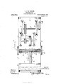
- Figure l is a side elevation of the improved device.
- Fig. 2 is a plan view of the same, with the knife holding device detached.
- Fig. 3 is a sectional detail illustrating the manner of reversing the knives to enable both sides to be actuated upon.
- Fig. 4 is an enlarged detail partly in section, illustrating the construction of the knife holding portion of the device.
- Fig. 5 is a sectional detail on the line 5 5 of Fig. 4.
- the improved device comprises a base l0 of any suitable material, but is preferably of wood and provided with vertical handles 11-12 at the ends to facilitate the trans portation of the device.
- a transverse stop member 13 Connected to the base 10 and spaced from one end is a transverse stop member 13 which thus forms a receptacle 14 at one end of the base for all of the knives except the one in the holder', and which is being acted upon.
- guard plate 28 Bearing upon the upper face of the base 10 and projecting partially over the channel 26 at one side is a guard plate 28, while similar guard plates 29--30 are arranged to project partly over the opposite side of the channel. Similar guard plates 31--32 are also arranged to project partly over the channel 27.
- the two channels 26- ⁇ 27 are thus in constant communication, as shown.
- a ball 33 Movably disposed in the channels 26-27 is a ball 33, and rising from the ball 33 is a standard orrod 34, the rod extending between the plates 28--30 and 31 32, as will be obvious.
- a standard orrod 34 By this means the ball 33 and the rod 34 may be freely moved within the channels 26-27 to any required extent, as hereinafter explained.
- stop devices preferably inthe form of detachable hooks as shown at 35--36, to pre vent the accidental displacement' of the ball 33, while at the same time providing means for the removal of the ball and its standard when required.
- a stock 37 Extending upwardly from the standard 34 is a stock 37 having its lower portion longitudinally bored to form a sleeve 38 and with a slot 39 through the bored portion, and which is slidable over the standard, and with a spring 40 between the standard and the inner end of the bore, the spring operating to maintain the stock 37 yieldably in its outward position.
- a pin 4l extends through the standard 34 and likewise through the slots 39 and thus limits the movement of the stock in one direction.v
- Operating handles 4.2-43 are arranged to project in opposite directions from the stock 37 to enable the latter to be manually adjusted as hereinafter explained.
- a jaw member 44 Connected to the upper end of the stock 37 is a jaw member 44, the jaw member being rigidly coupled as at 45 to the stock.V
- the jaws 44 and 47 are provided with transverse slots 50-51, and pivoted at 52 in the slot 51 is a clamp bolt 53, the bolt extending through the other slot 50 and provided with a wing nut 54 operating against the outer face of the jaw 47.
- a clamp bolt 53 the bolt extending through the other slot 50 and provided with a wing nut 54 operating against the outer face of the jaw 47.
- the operator can thus grind one side of the blade by moving it back and forth in contact with the grinding wheel, the channel 26 serving to support the lower end of the knife carrying mechanism in position, and insuring a uniform action upon the knife blade.
- the blade will move vertically as required to insure the requisite grinding effect, the longitudinal movement of the stock 37 thus permitting any required adjustment to secure any required grinding efl'ect.
- the blade supporting members 34-37 are moved i-nto a vertical position and the ball posite face of the blade will be toward theA l.
- a base having a plurality of communicating channels formed in its upper surface, a frame carried by said base, a grinding wheel mounted in said frame, means to rotate said wheel, a yieldable work-supporting pillar, a ball-end on said pillar adapted to slide in said channels, and
- a base having a channel formed in its upper surface and a second channel perpendicular to and intersecting the first, a frame carried by said base, a grinding wheel mounted in said frame with its axis parallel to one of said channels, means to rotate said wheel, a yieldable work-supporting pillar, a ball end on said pillar adapt/ed to slide in the channels, and means for retaining said ball in said channels.
- a device for sharpening edged tools comprising a base having a channel formed in its upper surface and a second channel perpendicular to and intersecting the first., a frame carried by said base, a grinding wheel mounted in said frame with its axis parallel to the first of said channels, a telescoping work supporting pillar normally retained in extended position by a compression spring housed within the telescoping members, a ball end on said pillar adapted to slide in said channels, means for retaining said ball in said channels, and means for rotating said grinding wheel.
- a device for sharpening edged tools comprising a base having a channel formed in its upper surface and a second channel perpendicular to and intersecting the first, a frame carried by said base, a grinding wheel mounted in said frame with its axis parallel to the first of said channels, a telescoping work-supporting pillar normally retained in extended position by a compression spring housed within the telesooping members, a pair of clamp jaws secured to the upper end of said pillar, a ball base on said pillar adapted to slide in said channels, means for retaining said ball in said channels, and means for rotating said grinding In testimony whereof, I aiix my signature in presence of two witnesses.
Landscapes
- Engineering & Computer Science (AREA)
- Mechanical Engineering (AREA)
- Finish Polishing, Edge Sharpening, And Grinding By Specific Grinding Devices (AREA)
Description
3 SHEETS-SHEET 1.
.Patented May 3o, 1911.
B. A.-T1IIELEMANN. KNIFE SHARPBNER.
APPLIUATION FILED co1'. 4, 1910.'
- 993,734. Patented May 30,1911.
hm/M301,
f4 gie /ema/f/l.
vnl Naam: Plfnu w.. wAsmNuvoN. n. c`
E. A. THIELEMANN.
KNIFE SHABPBNEB.
APPLIUATION FILED 0012.4, 1910.
993,734. 4 Patented May 30, 1911.
3 SHEETS-SHEET 3.
UNiTED srnras PATENT ernten.
vERNEST A. THIELEMANN, OF ALMORAH CRESCENT, JERSEY, ENGLAND.
KNIFE-SHARPENER.
Patented May 30, 1911.
9'9734, Specication of Letters Patent.
Application filed October 4, 1910. Serial No. 585,293.
To all whom it may concern:
Be it known `that I, ERNEST ALBERT THIELEMANN, a subject of the Emperor of Germany, residing at Almorah Crescent, Jersey, Channel Islands, England, have invented certain new and` useful Improvements in Knife-Sharpeners; and I do hereby declare the following to be a full, clear, and exact description of the invention, such as will enable others skilled in the art to which it appertains to make and use the same.
This invention relates to improvements in devices for sharpening knives and for like purposes, and has for one of its objects to provide a simply constructed device whereby kitchen knives and like implements may be accurately and readily sharpened by any person without previous skill or knowledge.
Another object of the invention is to provide a device of this character which is readily adjusted to knives of various sizes and shapes.
With these and other objects in View, the invention consists in certain novel features of construction as hereinafter shown and. described; and, then specifically pointed out in the claims, and in the drawings illustrative of the preferred embodiment of the invention, Figure l is a side elevation of the improved device. Fig. 2 is a plan view of the same, with the knife holding device detached. Fig. 3 is a sectional detail illustrating the manner of reversing the knives to enable both sides to be actuated upon. Fig. 4 is an enlarged detail partly in section, illustrating the construction of the knife holding portion of the device. Fig. 5 is a sectional detail on the line 5 5 of Fig. 4.
The improved device comprises a base l0 of any suitable material, but is preferably of wood and provided with vertical handles 11-12 at the ends to facilitate the trans portation of the device.
Connected to the base 10 and spaced from one end is a transverse stop member 13 which thus forms a receptacle 14 at one end of the base for all of the knives except the one in the holder', and which is being acted upon.
will preferably be an emery wheel or the like. Rising from the base 10 are two other brackets 20-21 which support another shaft 22 having an operating crank 23 and a belt pulley 24. The pulleys 19-24 are arranged in ahnement and connected by an operating belt 25. By this means it will be obvious that the shaft 22 is rotatable by the crank 23, and its motion communicated by the pulleys and' belt to the shaft 17 and the C grinding wheel, and at a greatly increased speed. Formed in the upper face of the ba se 10 is a channel 26, while a shorter longitudinal channel 27 is likewise formed in the upper face of the base and centrally thereof and communicates with the channel 26, as shown. Bearing upon the upper face of the base 10 and projecting partially over the channel 26 at one side is a guard plate 28, while similar guard plates 29--30 are arranged to project partly over the opposite side of the channel. Similar guard plates 31--32 are also arranged to project partly over the channel 27. The two channels 26-` 27 are thus in constant communication, as shown.
Movably disposed in the channels 26-27 is a ball 33, and rising from the ball 33 is a standard orrod 34, the rod extending between the plates 28--30 and 31 32, as will be obvious. By this means the ball 33 and the rod 34 may be freely moved within the channels 26-27 to any required extent, as hereinafter explained. Connected to the base l0 at the opposite ends of the channel 26 are stop devices preferably inthe form of detachable hooks as shown at 35--36, to pre vent the accidental displacement' of the ball 33, while at the same time providing means for the removal of the ball and its standard when required.
Extending upwardly from the standard 34 is a stock 37 having its lower portion longitudinally bored to form a sleeve 38 and with a slot 39 through the bored portion, and which is slidable over the standard, and with a spring 40 between the standard and the inner end of the bore, the spring operating to maintain the stock 37 yieldably in its outward position. A pin 4l extends through the standard 34 and likewise through the slots 39 and thus limits the movement of the stock in one direction.v Operating handles 4.2-43 are arranged to project in opposite directions from the stock 37 to enable the latter to be manually adjusted as hereinafter explained. Y,
Connected to the upper end of the stock 37 is a jaw member 44, the jaw member being rigidly coupled as at 45 to the stock.V
beyond the jaws, as represented in Fig. 3.
At their free ends the jaws 44 and 47 are provided with transverse slots 50-51, and pivoted at 52 in the slot 51 is a clamp bolt 53, the bolt extending through the other slot 50 and provided with a wing nut 54 operating against the outer face of the jaw 47. By this means an efficient clamping device is provided whereby the jaws may be firmly clamped against the knife blade represented at 55.
"With a device thus constructed, the operation is as follows: The wing nut 54 is loosened to enable the bolt 53 to be swung around free from the slot 50 so that the jaw 47 may be swung outwardly to enable the knife blade to be inserted therein as shown in Fig. 3. The jaw 47 is 'then clamped against the knife blade by means of the bolt 53 and the wing nut 54. The spring 40 operates to maintain the cutting edge of the knife blade at the highest point relative to the grinding wheel 18, and the operator holds the blade against the cutting wheel and moves it over the same by sliding the ball 33 in the channel 26. The operator can thus grind one side of the blade by moving it back and forth in contact with the grinding wheel, the channel 26 serving to support the lower end of the knife carrying mechanism in position, and insuring a uniform action upon the knife blade. By downward pressure applied to the handle 42 or 43, as the case may be, the blade will move vertically as required to insure the requisite grinding effect, the longitudinal movement of the stock 37 thus permitting any required adjustment to secure any required grinding efl'ect. When one edge of the blade has been properly ground the blade supporting members 34-37 are moved i-nto a vertical position and the ball posite face of the blade will be toward theA l. A device for` sharpening edged tools,.
comprising a base having a plurality of communicating channels formed in its upper surface, a frame carried by said base, a grinding wheel mounted in said frame, means to rotate said wheel, a yieldable work-supporting pillar, a ball-end on said pillar adapted to slide in said channels, and
means for retaining said ball in said channels.
2. ln a device for sharpening edged tools,-
including a base and a frame supported thereby, the combination with a grinding wheel mounted in the frame and means to rotate said wheel of an extensible worksupporting pillar, means operated by a spring for retaining the pillar at a fixed eX- tension, and a ball end formed on said pillar and slidable in a channel in said base.
3. A device for sharpening edged tools,
comprising a base having a channel formed in its upper surface and a second channel perpendicular to and intersecting the first, a frame carried by said base, a grinding wheel mounted in said frame with its axis parallel to one of said channels, means to rotate said wheel, a yieldable work-supporting pillar, a ball end on said pillar adapt/ed to slide in the channels, and means for retaining said ball in said channels.
4. A device for sharpening edged tools, comprising a base having a channel formed in its upper surface and a second channel perpendicular to and intersecting the first., a frame carried by said base, a grinding wheel mounted in said frame with its axis parallel to the first of said channels, a telescoping work supporting pillar normally retained in extended position by a compression spring housed within the telescoping members, a ball end on said pillar adapted to slide in said channels, means for retaining said ball in said channels, and means for rotating said grinding wheel. l
5. A device for sharpening edged tools, comprising a base having a channel formed in its upper surface and a second channel perpendicular to and intersecting the first, a frame carried by said base, a grinding wheel mounted in said frame with its axis parallel to the first of said channels, a telescoping work-supporting pillar normally retained in extended position by a compression spring housed within the telesooping members, a pair of clamp jaws secured to the upper end of said pillar, a ball base on said pillar adapted to slide in said channels, means for retaining said ball in said channels, and means for rotating said grinding In testimony whereof, I aiix my signature in presence of two witnesses.
ERNEST A. THIELEMANN.
Witnesses ALLREANT, HERBERT M. GnsAU'r.
Copies of this patent may be obtained for five cents each, by addressing the Commissioner of Patents, Washington, D. O.
Priority Applications (1)
| Application Number | Priority Date | Filing Date | Title |
|---|---|---|---|
| US58529310A US993734A (en) | 1910-10-04 | 1910-10-04 | Knife-sharpener. |
Applications Claiming Priority (1)
| Application Number | Priority Date | Filing Date | Title |
|---|---|---|---|
| US58529310A US993734A (en) | 1910-10-04 | 1910-10-04 | Knife-sharpener. |
Publications (1)
| Publication Number | Publication Date |
|---|---|
| US993734A true US993734A (en) | 1911-05-30 |
Family
ID=3062067
Family Applications (1)
| Application Number | Title | Priority Date | Filing Date |
|---|---|---|---|
| US58529310A Expired - Lifetime US993734A (en) | 1910-10-04 | 1910-10-04 | Knife-sharpener. |
Country Status (1)
| Country | Link |
|---|---|
| US (1) | US993734A (en) |
Cited By (1)
| Publication number | Priority date | Publication date | Assignee | Title |
|---|---|---|---|---|
| US2593847A (en) * | 1947-11-26 | 1952-04-22 | Clark John Wesley | Toolholder |
-
1910
- 1910-10-04 US US58529310A patent/US993734A/en not_active Expired - Lifetime
Cited By (1)
| Publication number | Priority date | Publication date | Assignee | Title |
|---|---|---|---|---|
| US2593847A (en) * | 1947-11-26 | 1952-04-22 | Clark John Wesley | Toolholder |
Similar Documents
| Publication | Publication Date | Title |
|---|---|---|
| US2782570A (en) | Grinding guide and carrier | |
| US719880A (en) | Grinding or sharpening device. | |
| US845487A (en) | Scissors-sharpener. | |
| US1801802A (en) | Cutlery sharpener | |
| US700562A (en) | Knife-sharpening device. | |
| US1141095A (en) | Sharpener for hair-clippers. | |
| US620021A (en) | Device for sharpening scissors or other tools | |
| US152422A (en) | Improvement in machines for cutting cork | |
| US193748A (en) | Improvement-in devices for | |
| US600947A (en) | Sharpening device | |
| US537411A (en) | Machine for concaving razors | |
| US2747341A (en) | Grinding machine | |
| US739028A (en) | Abrading-tool. | |
| US1817506A (en) | Sharpener for shears and scissors blades | |
| US653240A (en) | Grinding attachment for sewing-machines. | |
| US450191A (en) | Grindstone attachment | |
| US328375A (en) | Hay-knife grinder | |
| US929785A (en) | Sharpening apparatus. | |
| US293628A (en) | byron | |
| US616478A (en) | Scissors-sharpener | |
| US241750A (en) | Burnishing knife-blades | |
| US409337A (en) | Scarfing-machine | |
| US265577A (en) | Knife polisher and grinder | |
| US2435672A (en) | Sharpening device for knives | |
| US402465A (en) | Device to facilitate grinding sections of mowing-machines |