US993658A - Safety razor-guard. - Google Patents
Safety razor-guard. Download PDFInfo
- Publication number
- US993658A US993658A US59394010A US1910593940A US993658A US 993658 A US993658 A US 993658A US 59394010 A US59394010 A US 59394010A US 1910593940 A US1910593940 A US 1910593940A US 993658 A US993658 A US 993658A
- Authority
- US
- United States
- Prior art keywords
- razor
- guard
- blade
- extension
- bar
- Prior art date
- Legal status (The legal status is an assumption and is not a legal conclusion. Google has not performed a legal analysis and makes no representation as to the accuracy of the status listed.)
- Expired - Lifetime
Links
Images
Classifications
-
- B—PERFORMING OPERATIONS; TRANSPORTING
- B26—HAND CUTTING TOOLS; CUTTING; SEVERING
- B26B—HAND-HELD CUTTING TOOLS NOT OTHERWISE PROVIDED FOR
- B26B21/00—Razors of the open or knife type; Safety razors or other shaving implements of the planing type; Hair-trimming devices involving a razor-blade; Equipment therefor
- B26B21/02—Razors of the open or knife type; Safety razors or other shaving implements of the planing type; Hair-trimming devices involving a razor-blade; Equipment therefor involving unchangeable blades
Definitions
- the attaching member 9 BEVERLY DEUEL, OF LAPORTE, INDIANA.
- This invention relates to improvements in safety guardsfor razor blades and the lead ing object of the invention is to provide a device of this character which will guard the cutting edge of a razor blade and permit the razor to be stropped while the same is attached to the razor blade.
- Another object of the invention is to pro- Vide a safety guard for razor blades which may be readily attached to the blades of ordinary razors having pivoted handles and which while guarding the cutting edge of the razor blade will not interfere with close shaving.
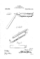
- FIG. 1 is a side elevation of a razor blade provided with the improved guard.
- Fig. 2 is a perspective view showing the guard detached from the razor blade.
- Fig. 3 is a plan view of an attachment for the back of the razor blade.
- 5 denotes a razor blade of the conventional type having the usual ground cutting edge 6 and an extension 7 on which the handle 8 is ivoted.
- an attaching member 9 is secured, said member being stamped out of sheet metal and formed into a semi-cylindrical body to resiliently engage the razor blade.
- the outer end of is formed with a small circular or disk portion 10 which is adapted to engage the terminal of the blade back and which is formed with a centrally disposed opening.
- the circular or disk portion 10 serves as a support for the pivot 11 of the uard arm 12 which arm is formed with a fiifurcated extension 13 that receives the end edge of the blade 5.
- the (guard arm 12 is integral with the longitu inall extendin and sinuousl curved guar bar 14:, w ich guard bar is ada ted to lie adjacent the e e 6 of the bla e 5.
- the guard bar 14 is ormed integral with a second arm 15 which terminates in a pivot extension 16 and is assed through the bearing 17, which is sol ered or otherwise fixed to the extension 7 of the blade 5.
- the bearin 7 so that t e arm 15, which is curved to corres 0nd with the curvature of the rear end e ge of the blade 5, will be held away from said blade.
- the sides of the bifurcated extension or stop 13 are spaced apart a sufficient distance to allow for a swinging movement of the guard bar14.
- the attachin member 9 may be secured to any razor bl lengthwise on the back thereof until the end member or bearing 10 will occupy a position adjacent to the endof the blade ack.
- the extension 16 will have engaged the member 17 for pivotal movement therein and the bifurcated extensions 13 ositioned astride the end of the razor bla e, thus allowing lateral swinging movement of the guard bar 14.
- the arms 12 and 15 may be connected to the bearings 17 and 10 and the bifurcated extension 13 dplaced astride the end edge of the razor bla e.
- a razor guard consisting of a corrugated bar, said bar being provided with an offset adapted to enter a securing device arranged adjacent the heel of a razor, offsets formed inte ral with the other end of said bar, said 0 sets being adapted to embrace the end portion of said razor, and a tubular member embracing the back of said razor, the end ortion of said member forming a bearing fdr the end portion of said bar.
- a razor guard consisting of a tubular member formed from a single piece of sheet metal and adapted to embrace the back of a razor, a corrugated bar havin one of its ends bent upwardly and pivotal y connected to the tubular member, said end being proade by sliding the same 17 is located on the extension 7 vided with bifurcated extensions for strad- In testimony whereof, I aflix my signedl'i'ng the end of the blade and its other end ture, in presence of two witnesses. terminating in an extension adapted to piv- BEVERLY DEUEL otally engage a, securing device formed ad- 5- jacent the heel of the razor, whereby the witnesseses:
- corrugated bar has a limited lateral swing JUENE DORLAND, ing movement. BEssm L. MORRISON.
Landscapes
- Life Sciences & Earth Sciences (AREA)
- Forests & Forestry (AREA)
- Engineering & Computer Science (AREA)
- Mechanical Engineering (AREA)
- Professional, Industrial, Or Sporting Protective Garments (AREA)
Description
B. DEUBL.
SAFETY RAZOR GUARD.
APPLICATION FILED 11011.23. 1910.
993,658. Patented May 30,1911.
awe/whoa:
Hawk/ y 04 09/.
alumina .the attaching member 9 BEVERLY DEUEL, OF LAPORTE, INDIANA.
SAFETY RAZOR-GUARD.
Specificationof Letters Patent.
Patented May 30, 1911.
Application filed November 23, 1910. Serial No. 593,940.
i To all whom it may concern:
Be it known that I, BEVERLY DEUEL, a citizen of the United States, residin at Laporte, in the county of Laporte, gtate of Indiana, have invented certain new and useful Im rovements in Safety Razor-Guards; and I o hereby declare the following to be a full, clear, and exact description of the invention, such as will enable others skilled in the art to which it appertains to make and use the same.
This invention relates to improvements in safety guardsfor razor blades and the lead ing object of the invention is to provide a device of this character which will guard the cutting edge of a razor blade and permit the razor to be stropped while the same is attached to the razor blade.
Another object of the invention is to pro- Vide a safety guard for razor blades which may be readily attached to the blades of ordinary razors having pivoted handles and which while guarding the cutting edge of the razor blade will not interfere with close shaving.
With the above and other objects in view the invention consists in certain constructions, combinations and arrangements of parts, clearly described in the following specification and clearly illustrated in the accompanying drawings, in which Figure 1 is a side elevation of a razor blade provided with the improved guard. Fig. 2 is a perspective view showing the guard detached from the razor blade. Fig. 3 is a plan view of an attachment for the back of the razor blade.
Referring to the accompanying drawings, 5 denotes a razor blade of the conventional type having the usual ground cutting edge 6 and an extension 7 on which the handle 8 is ivoted.
n the thickened edge of the blade 5 an attaching member 9 is secured, said member being stamped out of sheet metal and formed into a semi-cylindrical body to resiliently engage the razor blade. The outer end of is formed with a small circular or disk portion 10 which is adapted to engage the terminal of the blade back and which is formed with a centrally disposed opening. The circular or disk portion 10 serves as a support for the pivot 11 of the uard arm 12 which arm is formed with a fiifurcated extension 13 that receives the end edge of the blade 5.
The (guard arm 12 is integral with the longitu inall extendin and sinuousl curved guar bar 14:, w ich guard bar is ada ted to lie adjacent the e e 6 of the bla e 5. The guard bar 14 is ormed integral with a second arm 15 which terminates in a pivot extension 16 and is assed through the bearing 17, which is sol ered or otherwise fixed to the extension 7 of the blade 5. The bearin 7 so that t e arm 15, which is curved to corres 0nd with the curvature of the rear end e ge of the blade 5, will be held away from said blade. The sides of the bifurcated extension or stop 13 are spaced apart a sufficient distance to allow for a swinging movement of the guard bar14.
The attachin member 9 may be secured to any razor bl lengthwise on the back thereof until the end member or bearing 10 will occupy a position adjacent to the endof the blade ack. During this operation the extension 16 will have engaged the member 17 for pivotal movement therein and the bifurcated extensions 13 ositioned astride the end of the razor bla e, thus allowing lateral swinging movement of the guard bar 14. The arms 12 and 15 may be connected to the bearings 17 and 10 and the bifurcated extension 13 dplaced astride the end edge of the razor bla e.
I claim 1. A razor guard consisting of a corrugated bar, said bar being provided with an offset adapted to enter a securing device arranged adjacent the heel of a razor, offsets formed inte ral with the other end of said bar, said 0 sets being adapted to embrace the end portion of said razor, and a tubular member embracing the back of said razor, the end ortion of said member forming a bearing fdr the end portion of said bar.
2. A razor guard consisting of a tubular member formed from a single piece of sheet metal and adapted to embrace the back of a razor, a corrugated bar havin one of its ends bent upwardly and pivotal y connected to the tubular member, said end being proade by sliding the same 17 is located on the extension 7 vided with bifurcated extensions for strad- In testimony whereof, I aflix my signedl'i'ng the end of the blade and its other end ture, in presence of two witnesses. terminating in an extension adapted to piv- BEVERLY DEUEL otally engage a, securing device formed ad- 5- jacent the heel of the razor, whereby the Witnesses:
corrugated bar has a limited lateral swing JUENE DORLAND, ing movement. BEssm L. MORRISON.
Priority Applications (1)
| Application Number | Priority Date | Filing Date | Title |
|---|---|---|---|
| US59394010A US993658A (en) | 1910-11-23 | 1910-11-23 | Safety razor-guard. |
Applications Claiming Priority (1)
| Application Number | Priority Date | Filing Date | Title |
|---|---|---|---|
| US59394010A US993658A (en) | 1910-11-23 | 1910-11-23 | Safety razor-guard. |
Publications (1)
| Publication Number | Publication Date |
|---|---|
| US993658A true US993658A (en) | 1911-05-30 |
Family
ID=3061991
Family Applications (1)
| Application Number | Title | Priority Date | Filing Date |
|---|---|---|---|
| US59394010A Expired - Lifetime US993658A (en) | 1910-11-23 | 1910-11-23 | Safety razor-guard. |
Country Status (1)
| Country | Link |
|---|---|
| US (1) | US993658A (en) |
-
1910
- 1910-11-23 US US59394010A patent/US993658A/en not_active Expired - Lifetime
Similar Documents
| Publication | Publication Date | Title |
|---|---|---|
| US1533039A (en) | Multipower shears | |
| US2276556A (en) | Windshield wiper | |
| US1831579A (en) | Safety razor | |
| US1436603A (en) | Pruning device | |
| US1920954A (en) | Combination fish scaler and knife | |
| US851341A (en) | Safety-razor. | |
| US2033216A (en) | Shears | |
| US1959841A (en) | Safety razor | |
| US1470417A (en) | Shears or scissors | |
| US2399437A (en) | Blade sharpener for lawn mowers | |
| US928335A (en) | Hoof-nippers. | |
| US1701036A (en) | Distbict | |
| US2203714A (en) | Blade holder | |
| US2703450A (en) | Hair-tapering attachment for clippers | |
| US1973366A (en) | Windshield wiper | |
| US340053A (en) | Andeew jackson lytle | |
| US1057644A (en) | Safety-razor. | |
| US1513826A (en) | Blade movement for electric razors | |
| US1446383A (en) | Hair-cutting device | |
| US443773A (en) | Christian feiedeicii laufee | |
| US1275107A (en) | Hair-clipper. | |
| US1574232A (en) | Combined ax and blade guard therefor | |
| US408482A (en) | Horatio p | |
| US1758963A (en) | Safety razor | |
| US1395159A (en) | Safety-razor |