US9935438B2 - Door chime assembly - Google Patents
Door chime assembly Download PDFInfo
- Publication number
- US9935438B2 US9935438B2 US15/584,683 US201715584683A US9935438B2 US 9935438 B2 US9935438 B2 US 9935438B2 US 201715584683 A US201715584683 A US 201715584683A US 9935438 B2 US9935438 B2 US 9935438B2
- Authority
- US
- United States
- Prior art keywords
- electrical box
- transformer
- bracket
- assembly
- wall
- Prior art date
- Legal status (The legal status is an assumption and is not a legal conclusion. Google has not performed a legal analysis and makes no representation as to the accuracy of the status listed.)
- Expired - Fee Related
Links
Images





Classifications
-
- H—ELECTRICITY
- H02—GENERATION; CONVERSION OR DISTRIBUTION OF ELECTRIC POWER
- H02G—INSTALLATION OF ELECTRIC CABLES OR LINES, OR OF COMBINED OPTICAL AND ELECTRIC CABLES OR LINES
- H02G3/00—Installations of electric cables or lines or protective tubing therefor in or on buildings, equivalent structures or vehicles
- H02G3/02—Details
- H02G3/08—Distribution boxes; Connection or junction boxes
- H02G3/12—Distribution boxes; Connection or junction boxes for flush mounting
-
- G—PHYSICS
- G10—MUSICAL INSTRUMENTS; ACOUSTICS
- G10K—SOUND-PRODUCING DEVICES; METHODS OR DEVICES FOR PROTECTING AGAINST, OR FOR DAMPING, NOISE OR OTHER ACOUSTIC WAVES IN GENERAL; ACOUSTICS NOT OTHERWISE PROVIDED FOR
- G10K1/00—Devices in which sound is produced by striking a resonating body, e.g. bells, chimes or gongs
- G10K1/06—Devices in which sound is produced by striking a resonating body, e.g. bells, chimes or gongs the resonating devices having the shape of a bell, plate, rod, or tube
- G10K1/08—Details or accessories of general applicability
- G10K1/26—Mountings; Casings
-
- H—ELECTRICITY
- H01—ELECTRIC ELEMENTS
- H01F—MAGNETS; INDUCTANCES; TRANSFORMERS; SELECTION OF MATERIALS FOR THEIR MAGNETIC PROPERTIES
- H01F27/00—Details of transformers or inductances, in general
- H01F27/06—Mounting, supporting, or suspending transformers, reactors, or choke coils not being of the signal type
-
- H—ELECTRICITY
- H02—GENERATION; CONVERSION OR DISTRIBUTION OF ELECTRIC POWER
- H02G—INSTALLATION OF ELECTRIC CABLES OR LINES, OR OF COMBINED OPTICAL AND ELECTRIC CABLES OR LINES
- H02G15/00—Cable fittings
- H02G15/02—Cable terminations
- H02G15/06—Cable terminating boxes, frames or other structures
Definitions
- Door chimes typically include a chime, a transformer and at least one switch.
- the switch is operably connected to the chime through a wired or wireless connection such that the switch can be actuated remotely from the chime to operate the chime and produce a chime sound.
- the switch is commonly mounted at an exterior location proximate to a door, while the chime is mounted within an interior space such that occupants within the building can hear the chime sound.
- the chime is connected to a power source, for example, utility power servicing a house via a transformer, which lowers the voltage of the house power to an appropriate voltage for the chime.
- the transformer is frequently installed proximate to a junction box for the building, which is typically mounted away from the interior spaces most frequently occupied by occupants. As such, the wiring between the transformer and the chime can be routed a considerable distance.
- certain door chime assemblies position the transformer proximate to the chime to avoid challenges, time, and expense in routing the wiring, which can be particularly cumbersome in existing construction. While the close proximity of the transformer and chime reduces the requirement of extending wiring between the transformer and chime, the close proximity presents different challenges including: safely positioning the transformer and chime in close proximity, mounting the transformer and chime within the same or proximate wall or supporting structure and wiring the switch to the chime around the added bulk of the transformer.
- FIG. 1 is an exploded front perspective view of a door chime assembly according to an example of the present disclosure.
- FIG. 2 is a schematic diagram of a door chime assembly according to an example of the present invention.
- FIG. 3 is a rear perspective view of a transformer assembly according to an example of the present disclosure.
- FIG. 4 is a front view of the transformer assembly depicted in FIG. 3 .
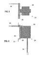
- FIG. 5 is a top view of the transformer assembly depicted in FIG. 3 .
- FIG. 6 is a side view of the transformer assembly depicted in FIG. 3 .
- FIG. 7 is a front perspective view of an electrical box according to an example of the present disclosure.
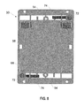
- FIG. 8 is a front view of the electrical box depicted in FIG. 7 .
- FIG. 9 is a top view of the electrical box depicted in FIG. 7 .
- FIG. 10 is a side view of the electrical box depicted in FIG. 7 .
- FIG. 11 is an exploded front perspective view of a door chime assembly according to an example of the present disclosure.
- FIG. 12 is a rear perspective view of a transformer assembly according to an example of the present disclosure.
- FIG. 13 is a top view of the transformer assembly depicted in FIG. 12 .
- FIG. 14 is a side view of the transformer assembly depicted in FIG. 12 .
- FIG. 15 is a front perspective view of an electrical box according to an example of the present disclosure.
- FIG. 16 is a front view of the electrical box depicted in FIG. 15 .
- FIG. 17 is a top view of the electrical box depicted in FIG. 15 .
- FIG. 18 is a side view of the electrical box depicted in FIG. 15 .
- FIG. 19 is a perspective view of a deployable tab according to an example of the present disclosure.
- Examples according to this disclosure are directed to, inter alia, challenges associated with proximately mounting a transformer and a door chime to avoid having to wire the chime to the transformer from a remote location.
- the present subject matter includes a door chime assembly including an electrical box mountable to a frame of a wall (e.g., a joist or stud), or the construction sheeting covering the wall frame (e.g., drywall, which is sometimes referred to as gypsum board).
- the door chime assembly can also include a transformer releasably coupled to a bracket.
- the transformer can be inserted into the electrical box through an opening in the box such that the bracket at least partially covers the opening to isolate the transformer within the electrical box and such that a low voltage portion and a high voltage portion of the transformer are disposed behind the bracket within the electrical box.
- the chime can be mounted proximate the bracket opposite the transformer.
- the transformer can include at least one high voltage input wire connected to the high voltage portion of the transformer behind the bracket and inserted through an inlet port in the box wall of the electrical box.
- the transformer can also include at least one low voltage output wire connected to the low voltage portion of the transformer behind the bracket and extending through a port in the bracket such that the chime can be wired to the transformer while isolated from the high voltage input wires by the bracket.
- the bracket can include at least one cover positioned over the port for the low voltage output wires to deflect the output wires exiting through the port in the bracket.
- the bracket can also include at least one clip for retaining a portion of the low voltage output wires against the bracket. The covers and clips can cooperate to position the ends of the output wires for coupling with the chime without slack portions.
- a door chime assembly 20 can include a chime 22 , a transformer assembly 24 and an electrical box 26 .
- the transformer assembly 24 can further include a bracket 28 and a transformer 30 releasably coupled to the bracket 28 .
- the transformer 30 includes a low voltage portion 30 a and a high voltage portion 30 b .
- the electrical box 26 can be mounted within a wall and can include a box wall 32 defining an interior space having at least one opening in the box wall 32 .
- the transformer 30 can be inserted into the interior space of the electrical box 26 through the opening such that the bracket 28 is positioned over or adjacent the opening.
- the chime 22 can be mounted proximate the bracket 28 opposite the transformer 30 such that the bracket 28 substantially separates and isolates the transformer 30 within the electrical box 28 .
- the bracket 28 and the box wall 32 cooperate to isolate the transformer 30 from the chime 22 and the surrounding wall structure.
- the transformer assembly 24 can include the bracket 28 and the transformer 30 .
- the transformer 30 can further include at least one high voltage input wire 34 that can be connected to the high voltage portion 30 b of the transformer 30 and wired to the house power and at least one low voltage output wire 36 that can be connected to the low voltage portion 30 a of the transformer 30 and wired to the chime 22 .
- the bracket 28 can define at least one outlet port 38 through which an end of each low voltage wire 36 can be inserted through the bracket 28 such that the bracket 28 isolates the inserted ends of the low voltage wires 36 from the transformer 30 and the high voltage input wires 34 .
- the bracket 28 can include at least one port cover 40 for deflecting at least one output wire 36 exiting through the outlet port 38 .
- the bracket 28 can include at least one clip 42 for retaining at least one output wire 36 against the bracket 28 .
- the bracket 28 can have various combinations of covers 40 and clips 42 , including no covers 40 and/or clips 42 , cooperating to position the inserted ends of the output wires 36 proximate to the input connectors of the chime 22 .
- the covers 40 and clips 42 can also cooperate to retain the output wires 36 to avoid slack in the output wires 36 that can become snagged during installation.
- the transformer 30 can further include at least one mounting element 44 .
- the bracket 28 can further include at least one transformer mount 46 corresponding to at least one of the mounting elements 34 .
- Each mounting element 44 can be releasably coupled to a corresponding transformer mount 46 to secure the transformer 30 to the bracket 28 .
- the transformer assembly 24 can include at least two pairs of mounting elements 44 and transformer mounts 46 that cooperate to engage the transformer 30 to the bracket 28 and prevent rotation of the transformer 30 relative to the bracket 28 .
- the mounting element 44 can include a clip releasably connected to the transformer 30 and the transformer mount 46 can include a planar element, for example, a pocket in a face of the bracket 28 sized to be engaged by the releasable clip as depicted in FIG. 4 .
- electrical box 26 can include a box wall 32 defining an interior space having at least one opening.
- the electrical box 26 can include an flange feature 48 proximate the opening and extending approximately perpendicular to the box wall 32 .
- the flange feature 48 extends from the two discrete portions of the box wall 32 , for example, the top and bottom of the box wall 32 .
- the electrical box could include a flange on different portions of the box wall, for example, the left and right sides, or a flange that extends around the periphery of the box wall.
- the flange feature 48 can be configured to seat the electrical box 26 on a wall of a house when the box is mounted within a hole in the wall, for example, within a hole in drywall.
- the transformer 30 is inserted through the opening of the electrical box 26 such that the bracket 28 is positioned over or adjacent the opening.
- a portion of the bracket 28 engages the inner flange feature 48 .
- the bracket 28 may seat within the opening such that the outward facing side of the bracket 28 lies substantially flush with the flange feature 48 .
- the bracket 28 can include a recessed portion 49 and a flanged portion 51 engagable to the inner flange feature 48 .
- the recessed portion 49 can receive a portion of the chime 22 to reduce protrusion of the chime 22 out from the wall.
- At least one fastener 50 is inserted through the bracket 28 and a portion of the electrical box to secure the bracket 28 to the electrical box 26 .
- the bracket 28 can define a notch 52 or bore hole for receiving the fastener 50 .
- the electrical box 26 can include a bore hole 54 corresponding to the notch 52 , wherein the fastener 50 can be inserted through the notch 52 and into the bore hole 54 to secure the bracket 28 to the box 26 .
- the bracket 28 can be sized to approximate the size of the opening of the electrical box 26 .
- the bracket 28 and the box wall 32 cooperate the isolate the transformer 30 within the interior space of the box wall 32 .
- the box wall 32 can include an inlet port 68 through which the high voltage input wires 34 can be inserted to reach the transformer 30 .
- the box wall 32 can define at least one wiring channel 56 on an exterior portion of the box wall 32 and a corresponding chime port 58 positioned at an end of the wiring channel 56 .
- the chime port 58 can be positioned proximate to the opening of the electrical box 26 such that wiring 59 for the chime 22 from a remotely positioned switch 61 can be threaded through the wiring channel 56 and the chime port 58 to exit through the opening of the electrical box 26 .
- the bracket 28 can include at least one notch 60 or opening corresponding to the chime port 58 .
- the notch 60 aligns with the chime port 58 when the bracket 28 is positioned within the opening of the electrical box 26 such that the switch wiring 59 can be threaded through the bracket 28 upon exiting the chime port 58 .
- the switch wiring 59 for the chime 22 is also isolated from the transformer 30 and the high voltage input wires 34 .
- the electrical box 26 can include at least one fastener feature 62 for receiving at least one stud fastener 64 .
- the stud fastener 64 is packaged and/or purchased separately from chime assembly 20 and electrical box 26 .
- the stud fastener 64 can be of a variety of standard construction nails and fastener feature 62 can be configured to receive such nails at the time of installation of chime assembly 20 .
- the electrical box 26 can include a plurality of fastener features 66 aligned linearly to guide the stud fastener 64 along a linear insertion axis.
- the linear insertion axis can be oriented to mount the electrical box 26 to a frame or stud.
- the stud fastener 64 can comprise a screw, a nail or a partially threaded nail.
- the electrical box 26 can be mounted such that the opening is positioned adjacent the frame or stud.
- the electrical box 26 can include at least one drywall engagement assembly 70 .
- Each engagement assembly 70 includes a stem 72 and a retention tab 74 .
- Each retention tab 74 is rotatable by rotating stem 72 between a retracted position in which the tab 74 is flush with the outside of box wall 32 and a deployed position in which the tab 74 extends transversely from the box wall 32 .
- the electrical box 26 can be inserted through an opening in an existing wall with the retention tabs 74 positioned in the retracted position. After the electrical box 26 is positioned within the wall, the tabs 74 are rotated into the deployed position by turning the stem 72 to retain the electrical box 26 within the wall.
- Stem 72 can, in some examples, be a threaded fastener like a screw, which can threadably engage tab 74 .
- the position of the tab 74 relative to flange feature 48 of electrical box 26 can be set by the length of stem 72 and the amount stem 72 is threadably engaged with tab 74 (e.g. axial length of stem 72 within bore in tab 74 ).
- the offset between the tab 74 and the flange feature 48 is set to accommodate a number of thicknesses of drywall in existing construction homes or other buildings.
- the offset between the tab 74 and the flange feature 48 may be set to in a range from approximately 0.75 inches to approximately 1.5 inches.
- the offset between the tab 74 and the flange feature 48 is in a range from approximately 0.5 to approximately 1 inch.
- the box wall 32 can include a stop 76 corresponding to each retention tab 74 .
- the stop 76 engages the corresponding tab 74 when the tab 74 is rotated into the deployed position to prevent rotation of the tab 74 past the deployed position.
- the stem 72 is threaded such that continued rotation of the stem 72 when the retention tab 74 is rotated into the deployed position and into engagement with the stop 76 causes the tab 74 to move axially relative to the stem 72 .
- the retention tab 74 can be moved axially into engagement with the inside of the existing wall to retain the electrical box 30 within the existing wall.
- the door chime assembly 20 can further include an alternative drywall engagement assembly 80 for installation of the door chime assembly 20 .
- retention tabs 84 are decoupled from the electrical box 26 before positioning the box in a hole in the wall and are coupled to the box 26 in a deployed position after the box is positioned in the hole in the wall.
- the engagement assembly 80 includes a threaded stem 82 and a deployable tab 84 having a threaded element 86 and a wall engagement portion 88 .
- the threaded element 86 defines a threaded bore hole for receiving the threaded stem 82 such that wall engagement portion 88 extends radially from the threaded stem 82 .
- rotation of the threaded stem 82 can operate to move the deployable tab 84 axially along the threaded stem 82 .
- the threaded stem 82 can be rotated to move deployable tab 84 axially until a portion of the wall is secured between the deployable tab 84 and the flange feature 48 of the electrical box 26 .
- the engagement assembly 80 can further include a guide element 90 .
- the electrical box 26 can define at least one slot 92 for receiving a corresponding guide element 90 to maintain the deployable tab 84 along a predetermined radial axis as the threaded stem 82 is rotated to move the deployable tab 84 axially.
- the slot 92 can receive guide element 90 to maintain the deployable tab 84 in a deployed position approximately perpendicular to box wall 32 and the threaded stem 82 can be rotated to move the deployable tab 84 axially.
- Slot 92 in box wall 32 of electrical box 26 terminates at a prescribed distance away from, for example, the opening in the box 26 .
- slot 92 may also function to stop deployable tab 84 from being pushed back when threaded stem 82 is initially threaded into threaded element 86 after deployable tab 84 has been inserted through box wall 32 of the electrical box 26 positioned in a hole in a wall.
- deployable tabs 84 may not be used and thus may even be discarded prior to installation.
- bracket 28 can include protrusions 94 positioned and shaped to cover the holes/slots in the box wall 32 of the electrical box 26 through which deployable tabs 84 are configured to be inserted.
- Example 1 is a door chime assembly comprising: an electrical box comprising a wall defining an interior space and an opening; and a transformer assembly coupled to the electrical box, the transformer assembly comprising: a bracket coupled to the electrical box; and a transformer releasably coupled to the bracket, the bracket at least partially covering the opening of the electrical box to isolate the transformer in the interior space of the electrical box.
- Example 2 the door chime assembly of Example 1, wherein the transformer comprises a low voltage portion and a high voltage portion disposed behind the bracket in the interior space of the electrical box.
- Example 3 the door chime assembly of Example 1 or 2, wherein the electrical box comprises an attachment element for attaching the electrical box to a frame element in a wall of a building.
- Example 4 the door chime assembly of any one of Examples 1-3, wherein the electrical box comprises an attachment element for attaching the electrical box to construction sheeting of a wall of a building.
- Example 5 the door chime assembly of Example 1 or 2, wherein the electrical box comprises: an attachment element for attaching the electrical box to a frame element in a wall of a building; and an attachment element for attaching the electrical box to construction sheeting of a wall of a building.
- Example 6 the door chime assembly of Example 1 or 2, wherein the electrical box comprises an attachment element for receiving a fastener for attaching the electrical box to a frame element in a wall of a building.
- Example 7 the door chime assembly of Example 1 or 2, wherein the electrical box comprises: an attachment element for receiving a fastener for attaching the electrical box to a frame element in a wall of a building; and an attachment element for attaching the electrical box to construction sheeting of a wall of a building.
- Example 8 the door chime assembly of any one of Examples 1-7, further comprising a door chime coupled to the bracket, the transformer being coupled to a first side of the bracket and the door chime being coupled to a second side of the bracket opposite the first side.
- Example 9 the door chime assembly of Example 8, further comprising a switch electrically connected to the door chime via at least one low voltage wire.
- Example 10 the door chime assembly of any one of Examples 1-9, further comprising at least one low voltage input wire and at least one high voltage input wire coupled to the transformer, the at least one low voltage input wire extending from the transformer through an aperture in the bracket.
- Example 11 the door chime assembly of Example 10, the bracket comprising a cover aligned with one side of the aperture and configured to deflect the at least one low voltage input wire extending through the aperture.
- Example 12 the door chime assembly of Example 11, the bracket comprising at least one clip retaining a portion of the at least one low voltage input wire extending through the aperture.
- the terms “a” or “an” are used, as is common in patent documents, to include one or more than one, independent of any other instances or usages of “at least one” or “one or more.”
- the term “or” is used to refer to a nonexclusive or, such that “A or B” includes “A but not B,” “B but not A,” and “A and B,” unless otherwise indicated.
Landscapes
- Engineering & Computer Science (AREA)
- Power Engineering (AREA)
- Physics & Mathematics (AREA)
- Acoustics & Sound (AREA)
- Multimedia (AREA)
- Architecture (AREA)
- Civil Engineering (AREA)
- Structural Engineering (AREA)
- Casings For Electric Apparatus (AREA)
Abstract
Description
Claims (11)
Priority Applications (1)
| Application Number | Priority Date | Filing Date | Title |
|---|---|---|---|
| US15/584,683 US9935438B2 (en) | 2014-08-15 | 2017-05-02 | Door chime assembly |
Applications Claiming Priority (3)
| Application Number | Priority Date | Filing Date | Title |
|---|---|---|---|
| US201462037985P | 2014-08-15 | 2014-08-15 | |
| US14/825,708 US20160049233A1 (en) | 2014-08-15 | 2015-08-13 | Door chime assembly |
| US15/584,683 US9935438B2 (en) | 2014-08-15 | 2017-05-02 | Door chime assembly |
Related Parent Applications (1)
| Application Number | Title | Priority Date | Filing Date |
|---|---|---|---|
| US14/825,708 Continuation US20160049233A1 (en) | 2014-08-15 | 2015-08-13 | Door chime assembly |
Publications (2)
| Publication Number | Publication Date |
|---|---|
| US20170237247A1 US20170237247A1 (en) | 2017-08-17 |
| US9935438B2 true US9935438B2 (en) | 2018-04-03 |
Family
ID=55302656
Family Applications (2)
| Application Number | Title | Priority Date | Filing Date |
|---|---|---|---|
| US14/825,708 Abandoned US20160049233A1 (en) | 2014-08-15 | 2015-08-13 | Door chime assembly |
| US15/584,683 Expired - Fee Related US9935438B2 (en) | 2014-08-15 | 2017-05-02 | Door chime assembly |
Family Applications Before (1)
| Application Number | Title | Priority Date | Filing Date |
|---|---|---|---|
| US14/825,708 Abandoned US20160049233A1 (en) | 2014-08-15 | 2015-08-13 | Door chime assembly |
Country Status (2)
| Country | Link |
|---|---|
| US (2) | US20160049233A1 (en) |
| CA (1) | CA2938555C (en) |
Families Citing this family (2)
| Publication number | Priority date | Publication date | Assignee | Title |
|---|---|---|---|---|
| CA3009295A1 (en) * | 2016-01-11 | 2017-07-20 | Ssb Wind Systems Gmbh & Co. Kg | Electrical switchgear cabinet |
| US12113341B2 (en) * | 2022-11-01 | 2024-10-08 | Reliance Controls Corporation | Power inlet box with circuit protection |
Citations (25)
| Publication number | Priority date | Publication date | Assignee | Title |
|---|---|---|---|---|
| US5574256A (en) * | 1994-12-08 | 1996-11-12 | Cottone; Thomas E. | Recessed transformer electrical outlet box with integral telephone line connection |
| US5596174A (en) | 1994-10-04 | 1997-01-21 | Sapienza; Joseph | Expandable electrical outlet box |
| US5600093A (en) | 1994-04-08 | 1997-02-04 | Herth; Greg B. | Dual purpose electrical box |
| US5603424A (en) | 1995-08-01 | 1997-02-18 | Thomas & Betts Corporation | Wall mounting assembly attachable to an electrical box |
| US6194657B1 (en) * | 1998-10-24 | 2001-02-27 | Arlington Industries, Inc. | Mounting device |
| US6207895B1 (en) * | 1999-03-24 | 2001-03-27 | Lucent Technologies Inc. | Device box for wall mounted communications apparatus |
| US6520363B1 (en) | 2001-08-30 | 2003-02-18 | Joseph Sullivan | Temporary protective cover for electrical outlet receptacle |
| US6533225B1 (en) | 2001-12-03 | 2003-03-18 | Dana Innovations | Wall-mounted audio control housing and receptacle therefor |
| US6573446B1 (en) | 1999-11-23 | 2003-06-03 | George H. Umstead | Apparatus for mounting an electrical component on a structure |
| US6737576B1 (en) * | 2003-05-16 | 2004-05-18 | Thomas & Betts International, Inc. | Electrical box assembly |
| US6818823B2 (en) | 2002-07-24 | 2004-11-16 | R. Lloyd Barnes | Quick installing, electric chime and back box |
| US6837726B1 (en) * | 2001-08-23 | 2005-01-04 | E.G.L. Company, Inc. | Holder for discharge lamp |
| US6940016B1 (en) * | 2003-08-06 | 2005-09-06 | Desa Ip, Llc | Electrical rough-in box for low voltage transformer |
| US6956168B2 (en) | 2003-07-19 | 2005-10-18 | Greg Herth | Horizontal electrical box |
| US7075004B1 (en) | 2003-06-07 | 2006-07-11 | Arlington Industries, Inc. | Integral low voltage/high voltage electrical box |
| US7129411B2 (en) | 2004-12-17 | 2006-10-31 | Bump Jeffrey A | Fastening system |
| US7394019B2 (en) | 2004-09-28 | 2008-07-01 | Rick Gesue | Compact flush-mount self-contained receptacle (SCR) |
| US7816604B1 (en) | 2004-06-09 | 2010-10-19 | Arlington Industries, Inc. | Recessed low voltage mounting assembly |
| US7842884B2 (en) | 2009-01-07 | 2010-11-30 | Johnson Richard A | Device and method for mounting an electrical box in drywall |
| US8076575B1 (en) | 2009-06-12 | 2011-12-13 | Arlington Industries, Inc. | Electrical box assembly for mounting and supporting a security camera or fixture |
| US8242360B2 (en) | 2010-05-29 | 2012-08-14 | Bercy Sr Rowland | Electrical junction box |
| US8344249B1 (en) | 2009-07-31 | 2013-01-01 | Hubbell Incorporated | Provisions for securement of an electrical box |
| US8389855B2 (en) * | 2003-12-12 | 2013-03-05 | Gary Dean Plankell | Recessed signal-receiver mounting system for a building structure and associated methods |
| US8720156B2 (en) | 2012-09-14 | 2014-05-13 | Charles Porter | Wall panel attachment system |
| US9392711B2 (en) * | 2012-10-03 | 2016-07-12 | Hayward Industries, Inc. | Electrical junction box with built-in isolation transformer |
-
2015
- 2015-08-13 US US14/825,708 patent/US20160049233A1/en not_active Abandoned
-
2016
- 2016-08-11 CA CA2938555A patent/CA2938555C/en active Active
-
2017
- 2017-05-02 US US15/584,683 patent/US9935438B2/en not_active Expired - Fee Related
Patent Citations (25)
| Publication number | Priority date | Publication date | Assignee | Title |
|---|---|---|---|---|
| US5600093A (en) | 1994-04-08 | 1997-02-04 | Herth; Greg B. | Dual purpose electrical box |
| US5596174A (en) | 1994-10-04 | 1997-01-21 | Sapienza; Joseph | Expandable electrical outlet box |
| US5574256A (en) * | 1994-12-08 | 1996-11-12 | Cottone; Thomas E. | Recessed transformer electrical outlet box with integral telephone line connection |
| US5603424A (en) | 1995-08-01 | 1997-02-18 | Thomas & Betts Corporation | Wall mounting assembly attachable to an electrical box |
| US6194657B1 (en) * | 1998-10-24 | 2001-02-27 | Arlington Industries, Inc. | Mounting device |
| US6207895B1 (en) * | 1999-03-24 | 2001-03-27 | Lucent Technologies Inc. | Device box for wall mounted communications apparatus |
| US6573446B1 (en) | 1999-11-23 | 2003-06-03 | George H. Umstead | Apparatus for mounting an electrical component on a structure |
| US6837726B1 (en) * | 2001-08-23 | 2005-01-04 | E.G.L. Company, Inc. | Holder for discharge lamp |
| US6520363B1 (en) | 2001-08-30 | 2003-02-18 | Joseph Sullivan | Temporary protective cover for electrical outlet receptacle |
| US6533225B1 (en) | 2001-12-03 | 2003-03-18 | Dana Innovations | Wall-mounted audio control housing and receptacle therefor |
| US6818823B2 (en) | 2002-07-24 | 2004-11-16 | R. Lloyd Barnes | Quick installing, electric chime and back box |
| US6737576B1 (en) * | 2003-05-16 | 2004-05-18 | Thomas & Betts International, Inc. | Electrical box assembly |
| US7075004B1 (en) | 2003-06-07 | 2006-07-11 | Arlington Industries, Inc. | Integral low voltage/high voltage electrical box |
| US6956168B2 (en) | 2003-07-19 | 2005-10-18 | Greg Herth | Horizontal electrical box |
| US6940016B1 (en) * | 2003-08-06 | 2005-09-06 | Desa Ip, Llc | Electrical rough-in box for low voltage transformer |
| US8389855B2 (en) * | 2003-12-12 | 2013-03-05 | Gary Dean Plankell | Recessed signal-receiver mounting system for a building structure and associated methods |
| US7816604B1 (en) | 2004-06-09 | 2010-10-19 | Arlington Industries, Inc. | Recessed low voltage mounting assembly |
| US7394019B2 (en) | 2004-09-28 | 2008-07-01 | Rick Gesue | Compact flush-mount self-contained receptacle (SCR) |
| US7129411B2 (en) | 2004-12-17 | 2006-10-31 | Bump Jeffrey A | Fastening system |
| US7842884B2 (en) | 2009-01-07 | 2010-11-30 | Johnson Richard A | Device and method for mounting an electrical box in drywall |
| US8076575B1 (en) | 2009-06-12 | 2011-12-13 | Arlington Industries, Inc. | Electrical box assembly for mounting and supporting a security camera or fixture |
| US8344249B1 (en) | 2009-07-31 | 2013-01-01 | Hubbell Incorporated | Provisions for securement of an electrical box |
| US8242360B2 (en) | 2010-05-29 | 2012-08-14 | Bercy Sr Rowland | Electrical junction box |
| US8720156B2 (en) | 2012-09-14 | 2014-05-13 | Charles Porter | Wall panel attachment system |
| US9392711B2 (en) * | 2012-10-03 | 2016-07-12 | Hayward Industries, Inc. | Electrical junction box with built-in isolation transformer |
Non-Patent Citations (2)
| Title |
|---|
| "U.S. Appl. No. 14/825,708: Non-Final Office Action dated Sep. 23, 2016". |
| "U.S. Appl. No. 14/825,708: Response to Non-Final Office Action filed Dec. 22, 2016". |
Also Published As
| Publication number | Publication date |
|---|---|
| CA2938555C (en) | 2021-10-26 |
| US20160049233A1 (en) | 2016-02-18 |
| US20170237247A1 (en) | 2017-08-17 |
| CA2938555A1 (en) | 2017-02-13 |
Similar Documents
| Publication | Publication Date | Title |
|---|---|---|
| US5221069A (en) | Telescoping support bracket | |
| US9705295B1 (en) | Slip conduit connector and system and method of installing electrical conduit with a slip conduit connector | |
| US7044318B2 (en) | Electrical box with recessed faceplate | |
| US8371465B2 (en) | Electrical box extension sleeve | |
| US6533225B1 (en) | Wall-mounted audio control housing and receptacle therefor | |
| US8076575B1 (en) | Electrical box assembly for mounting and supporting a security camera or fixture | |
| US7307213B1 (en) | Horizontal electrical box with internal mounting arrangement | |
| US8748744B2 (en) | Electrical box extender assembly | |
| US20080156510A1 (en) | Electrical junction box with a built-in fitting insert | |
| US20110290550A1 (en) | Electrical snap-in connector | |
| US20100032180A1 (en) | Add-a-depth ring and cover plate assembly | |
| US8044300B1 (en) | Two-gang low voltage mounting bracket with front plate and retractable clamp arms for rapid mounting using hole saw | |
| CA2938555C (en) | Door chime assembly | |
| US20080093099A1 (en) | Electrical Box Ring and Method for Manufacturing The Same | |
| JP6321721B2 (en) | Mounting device for mounting equipment and mounting method of mounting device | |
| US5853098A (en) | Repositioning backplate for an electrical outlet box | |
| US7282646B2 (en) | Wire support | |
| AU2008205446B2 (en) | Mounting box for electrical wiring accessories and assemblies and installations including such mounting box | |
| US20060131046A1 (en) | Fastening system | |
| US8076573B1 (en) | Electrical box hanger | |
| US20050093764A1 (en) | System and method for securing an antenna | |
| EP2716859B1 (en) | Tubular motor with support for a fixing element | |
| US8563857B2 (en) | Old construction box | |
| US8631955B2 (en) | Electrical service assembly and connecting system for mounting same in building structure wall | |
| US11705705B2 (en) | Mounting sleeve |
Legal Events
| Date | Code | Title | Description |
|---|---|---|---|
| AS | Assignment |
Owner name: BROAN-NUTONE LLC, WISCONSIN Free format text: ASSIGNMENT OF ASSIGNORS INTEREST;ASSIGNORS:JONAS, KENNETH JOHN;KARST, DANIEL L.;REEL/FRAME:044942/0500 Effective date: 20150826 |
|
| STCF | Information on status: patent grant |
Free format text: PATENTED CASE |
|
| AS | Assignment |
Owner name: U.S. BANK NATIONAL ASSOCIATION, AS COLLATERAL AGENT, TENNESSEE Free format text: SECURITY INTEREST;ASSIGNORS:BROAN-NUTONE LLC;NORTEK AIR SOLUTIONS, LLC;NORTEK GLOBAL HVAC, LLC;AND OTHERS;REEL/FRAME:056650/0303 Effective date: 20210621 Owner name: GOLDMAN SACHS BANK USA, AS COLLATERAL AGENT, NEW YORK Free format text: SECURITY INTEREST;ASSIGNORS:BROAN-NUTONE LLC;NORTEK AIR SOLUTIONS, LLC;NORTEK GLOBAL HVAC, LLC;AND OTHERS;REEL/FRAME:056647/0868 Effective date: 20210621 |
|
| MAFP | Maintenance fee payment |
Free format text: PAYMENT OF MAINTENANCE FEE, 4TH YEAR, LARGE ENTITY (ORIGINAL EVENT CODE: M1551); ENTITY STATUS OF PATENT OWNER: LARGE ENTITY Year of fee payment: 4 |
|
| FEPP | Fee payment procedure |
Free format text: MAINTENANCE FEE REMINDER MAILED (ORIGINAL EVENT CODE: REM.); ENTITY STATUS OF PATENT OWNER: LARGE ENTITY |
|
| LAPS | Lapse for failure to pay maintenance fees |
Free format text: PATENT EXPIRED FOR FAILURE TO PAY MAINTENANCE FEES (ORIGINAL EVENT CODE: EXP.); ENTITY STATUS OF PATENT OWNER: LARGE ENTITY |
|
| STCH | Information on status: patent discontinuation |
Free format text: PATENT EXPIRED DUE TO NONPAYMENT OF MAINTENANCE FEES UNDER 37 CFR 1.362 |
|
| FP | Lapsed due to failure to pay maintenance fee |
Effective date: 20260403 |