US993477A - Machine for finishing heels and soles for boots and shoes. - Google Patents
Machine for finishing heels and soles for boots and shoes. Download PDFInfo
- Publication number
- US993477A US993477A US10642402A US1902106424A US993477A US 993477 A US993477 A US 993477A US 10642402 A US10642402 A US 10642402A US 1902106424 A US1902106424 A US 1902106424A US 993477 A US993477 A US 993477A
- Authority
- US
- United States
- Prior art keywords
- work
- actuator
- members
- machine
- axis
- Prior art date
- Legal status (The legal status is an assumption and is not a legal conclusion. Google has not performed a legal analysis and makes no representation as to the accuracy of the status listed.)
- Expired - Lifetime
Links
- 230000002093 peripheral effect Effects 0.000 description 3
- 230000001788 irregular Effects 0.000 description 2
- 239000000463 material Substances 0.000 description 2
- 239000011435 rock Substances 0.000 description 2
- 230000015572 biosynthetic process Effects 0.000 description 1
- 230000006835 compression Effects 0.000 description 1
- 238000007906 compression Methods 0.000 description 1
- 238000010276 construction Methods 0.000 description 1
Images
Classifications
-
- A—HUMAN NECESSITIES
- A43—FOOTWEAR
- A43D—MACHINES, TOOLS, EQUIPMENT OR METHODS FOR MANUFACTURING OR REPAIRING FOOTWEAR
- A43D95/00—Shoe-finishing machines
- A43D95/20—Machines for burnishing soles or heels
Definitions
- This invention relates to means designed specifically for finishing heels, but is applicable to many other uses, and the object of the invention is to provide an improved means for this purpose.
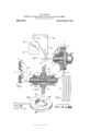
- FIG. 1 is an end elevation
- Fig. 2 is a section on line 2 of Fig. 1
- Fig. 3 is a view similar to Fig. 2 showing a plurality of work-members.
- Fig. 4c is a development of the acting face of the tool provided with a plurality of work-members, as shown in Fig. 3.
- Figs. 5 and 6 are perspective views, Fig. 6 being in section, of one of the work-members of Figs. 3 and 4 and illustrate the angular arrangement or oblique disposition of the body portion of the work-member with relation to its hub and its axis of rotation.
- the actuator 2 shown in the present instance as consisting of a shaft, may be journaled and revolved by power suitably applied thereto in any convenient manner.
- a medium 8 shown in this instance as composed of a metallic wire coiled spirally, and held under compression between the collars 3 and t for rotation with the actuator.
- a work-member 10 On the medium 8 is mounted a work-member 10, 2), its periphery 12 constituting a work-rubbing face.
- the screws 14 enter chamber 16 in member 10, thereby causing it to revolve with the actuator.
- the medium 8 is raised from the surface 20 of actuator 2 which is below or subjacent to the work-member whereby to permit yielding toward the actuator, thereby respending to the pressure of work on member 10.
- the chambers 16 are larger than the size of screws 14:. Said movement of the member 10, it will be observed, is made to take place in lines approximately perpendicular to the axis of the actuator 2, and
- the combination permits such movement to take place in all directions.
- a tool comprising a plurality of work-members 13, 15, 17 and 19, which are mounted side by side upon a yielding medium 8. These work-members are each formed as shown in Figs. 3, 5, and 6 with hubs 30 and with body portions 32.
- the axis of rotation of the tool is indicated by the line a-b and the lines c-d in this figure and a-a in Fig. 3 are perpendicular to the axis of the tool.
- body portion 32 of the work-member is obextend obliquely across the working face of the tool, as is shown in Fig. 4, and the acting face of one portion of any work-member as, for example, the upper portion marked a: in Fig. 3 and in the development shown in Fig. L-covers the space between that work-member and the adjacent work-member at another portion of the too-l--as the lower portion marked y in Figs. 3 and 4.
- the several Work-members are arranged side by side with their axes in alinement and concentric with or parallel to the axis of the actuator, as shown in Fig.
- the work as, for example, a boot or shoe heel
- the work-members In operation of the machine the work, as, for example, a boot or shoe heel, is presented to and pressed against the peripheral face of the work-members and turned for bringing the whole face of the heel to be treated into bearing with the rapidly revolving members.
- the several work-members yield independently of each other, and, shifting position relatively, will conform generally to the transverse curvature of the heel, so that a single turning of the heel longitudinally is sufiicient for the finishing operation.
- a wax-holding reservoir is provided (Fig. 1).
- the wheel 24 is arranged to operate in the melted wax held by said reservoir and, being rotated, lifts the wax on to a flexible ribbon or belt 26 which is made to travel over pulleys 28 and distribute the wax to the working-face of member 10.
- a wax carrier of the ribbon or belt formation a sharp bend is provided to contact with the member 10, thereby allowing of a member being used with small diameter and give ample space for turning the work.
- a machine for the purpose stated comprising a rotary actuator, a cylindrical workmember mounted on the actuator and connected to the actuator for rotation therewith, and a spring arranged between the actuator and the work-member out of contact with the actuator for yieldingly supporting the workmember, said parts being constructed and arranged to permit the work-member to yield freely toward the axis of the actuator as a shoe is pressed against the work-member during the operation of the machine.
- a machine for the purposes stated comprising a rotary actuator, a yielding medium surrounding the actuator, out of contact with the subjacent face of the actuator and a cylindrical workmember mounted on said yielding medium and arranged for free movement toward and from the axis of the actuator and for tipping movement with relation to the axis of the actuator.
- a machine for the purposes stated comprising an actuator and a plurality of separate work-members mounted side by side on said actuator and spaced apart to permit tipping movement of the work-members relatively to the actuator and a single spring arranged intermediate the work-members and the actuator and acting uniformly on the several work-members to maintain them yieldingly in their normal position.
- a machine for the purposes stated comprising a rotary actuator, a plurality of cylindrical work-members independently mounted for movement toward and from the actuator in lines of different direction with relation to the axis of the actuator, and a yielding medium intermediate the actuator and the work-members.
- a machine for the purposes stated com prising a rotary actuator and a plurality of work-members arranged side by side and yieldingly mounted upon the actuator for independent movement relatively thereto in directions angular to the axis of the actuator, and means connecting the work-members to the actuator whereby they are compelled to rotate with the actuator.
- a rotary actuator a plurality of work-members mounted side by side thereon, and having their peripheral edges out of contact and a yielding medium formed of a single piece of material arranged between the actuator and the work-members and spaced from the adjacent face of the actuator.
- a machine for the purposes stated comprising a rotary actuator, a plurality of sepa-' rate disks encircling the actuator, and a yielding medium intermediate the actuator and the disks arranged to permit movement of the disks toward and from the actuator separately in lines of different angularity to the axis of the actuator.
- an actuator a plurality of work-members arranged side by side with their working faces extending obliquely to the plane of movement of the work-members, and a yielding medium arranged between the work-members and the actuator and arranged to permit the Work-members to yield separately for changing the contour of the periphery of the tool.
- a shaft and a plurality of rotary Work-members arranged side by side With their axes in alinement and parallel to the axis of the shaft and their side surfaces extending at an oblique angle to the axis of the shaft.
- a shaft a plurality of cylindrical Work-members arranged side by side on said shaft and spaced apart With their Work-rubbing surfaces extending obliquely with relation to the plane of rotation of the Work-members.
Landscapes
- Forging (AREA)
Description
C. B. TUTTLE.
MACHINE FOR FINISHING HEELS AND sows FO-R BOOTS AND SHOES.
APPLICATION FILED MAY 8, 1902.
Patented May 30, 1911.
hurrah sraa ns ggrnn r orrron.
CALVIN B. TUTTLE, OF LYNN, MASSACHUSETTS, ASSIGNOR TO UNITED-XPEDITE FINISHING COMPANY, OF BERWIOK, MAINE, A CORPORATION OF MAINE.
MACHINE FOR FINISHING HEELS AND SOLES FOR BOOTS AND SHOES.
T 0 all whom it may concern:
Be it known that I, CALVIN B. TUTTLE, of Lynn, county of Essex, and Commonwealth of Massachusetts, have invented certain new and useful Improvements in Machines for Finishing Heels and Soles for Boots and Shoes, of which the following, read in connection with the accompanying drawings, is a specification.
This invention relates to means designed specifically for finishing heels, but is applicable to many other uses, and the object of the invention is to provide an improved means for this purpose.
Of the drawings Figure 1 is an end elevation; Fig. 2 is a section on line 2 of Fig. 1; Fig. 3 is a view similar to Fig. 2 showing a plurality of work-members. Fig. 4c is a development of the acting face of the tool provided with a plurality of work-members, as shown in Fig. 3. Figs. 5 and 6 are perspective views, Fig. 6 being in section, of one of the work-members of Figs. 3 and 4 and illustrate the angular arrangement or oblique disposition of the body portion of the work-member with relation to its hub and its axis of rotation.
The actuator 2, shown in the present instance as consisting of a shaft, may be journaled and revolved by power suitably applied thereto in any convenient manner. On the actuator are collars 3, 4, which are secured adjustably on the actuator by screws 5, 6. Encircling the actuator is a medium 8, shown in this instance as composed of a metallic wire coiled spirally, and held under compression between the collars 3 and t for rotation with the actuator. On the medium 8 is mounted a work-member 10, 2), its periphery 12 constituting a work-rubbing face. The screws 14 enter chamber 16 in member 10, thereby causing it to revolve with the actuator.
The medium 8 is raised from the surface 20 of actuator 2 which is below or subjacent to the work-member whereby to permit yielding toward the actuator, thereby respending to the pressure of work on member 10. To facilitate this yielding movement of member 10 the chambers 16 are larger than the size of screws 14:. Said movement of the member 10, it will be observed, is made to take place in lines approximately perpendicular to the axis of the actuator 2, and
Specification of Letters Patent.
Application filed May 8, 1902.
Patented May 30, 1911.
Serial No. 106,424.
the combination permits such movement to take place in all directions.
It is desirable, at times, for the member 10 to rock laterally in response to pressure applied on one edge of the work-face 12, whereby the member is caused to adjust itself conformably with the irregular con tour of work applied thereto. To this end collar 3 is adjusted to a distance from the member 10 which will permit the required rocking movement to take place. In such movement the member is tipped to a position with its axis slightly angular to the axis of the actuator 2, in which position the medium .8 yieldingly supports the member, still permitting movement of the member toward the actuator. This rocking movement of the work-member may be limited by the member contacting on the collars 3 and 4. As shown, the member 10 encircles the actuator 2 with its axis normally concentric with or parallel to the axis of the actuator. In operation the work, being pressed on the work-member face 12, will primarily start the work-member 10 forwardly in a line perpendicular to the axis of the actuator. In such forward movement the member, if
permitted so to do, may rock laterally, thereby bringing its face into bearing with irregular contours of work applied thereto. In such manner the work-member is accommodated to the inequalities of the boot or shoe heel. The member, being rapidly re-.
volved, possesses a yielding quality incident to the medium 8 on which it is supported.
In Fig. 3 is shown a tool comprising a plurality of work-members 13, 15, 17 and 19, which are mounted side by side upon a yielding medium 8. These work-members are each formed as shown in Figs. 3, 5, and 6 with hubs 30 and with body portions 32. In Fig. 6 the axis of rotation of the tool is indicated by the line a-b and the lines c-d in this figure and a-a in Fig. 3 are perpendicular to the axis of the tool. The
body portion 32 of the work-member is obextend obliquely across the working face of the tool, as is shown in Fig. 4, and the acting face of one portion of any work-member as, for example, the upper portion marked a: in Fig. 3 and in the development shown in Fig. L-covers the space between that work-member and the adjacent work-member at another portion of the too-l--as the lower portion marked y in Figs. 3 and 4. The several Work-members are arranged side by side with their axes in alinement and concentric with or parallel to the axis of the actuator, as shown in Fig. 3 and the opposing side faces of the work-members are parallel but extend at an oblique angle to the axis of the actuator, as will be clear from the drawings. The construction of other parts of the tool shown in Fig. 3 is substantially the same as in Fig. 2. In 0 crating, the work being pressed on the peripheral faces of said members 18, 15, 17, 19, will start the members forwardly in lines perpendicular to the axis of actuator 2 against the tension of medium 8, and, in such movement, the medium 8, yielding endwise, will permit the members to separate and tilt laterally in response to the diflerent contours of the work applied. All creasing of the work incident to the joints between said work-members is avoided by the disposition of the working faces obliquely across the periphery of the tool, as shown in Fig. 3.
In operation of the machine the work, as, for example, a boot or shoe heel, is presented to and pressed against the peripheral face of the work-members and turned for bringing the whole face of the heel to be treated into bearing with the rapidly revolving members. In such operation, the several work-members yield independently of each other, and, shifting position relatively, will conform generally to the transverse curvature of the heel, so that a single turning of the heel longitudinally is sufiicient for the finishing operation.
It is desirable at times to apply wax or other similar material. In this connection a wax-holding reservoir is provided (Fig. 1). The wheel 24 is arranged to operate in the melted wax held by said reservoir and, being rotated, lifts the wax on to a flexible ribbon or belt 26 which is made to travel over pulleys 28 and distribute the wax to the working-face of member 10. By using a wax carrier of the ribbon or belt formation a sharp bend is provided to contact with the member 10, thereby allowing of a member being used with small diameter and give ample space for turning the work.
Having now described my invention I claim 1. A machine for the purpose stated, comprising a rotary actuator, a cylindrical workmember mounted on the actuator and connected to the actuator for rotation therewith, and a spring arranged between the actuator and the work-member out of contact with the actuator for yieldingly supporting the workmember, said parts being constructed and arranged to permit the work-member to yield freely toward the axis of the actuator as a shoe is pressed against the work-member during the operation of the machine.
2. A machine for the purposes stated, comprising a rotary actuator, a yielding medium surrounding the actuator, out of contact with the subjacent face of the actuator and a cylindrical workmember mounted on said yielding medium and arranged for free movement toward and from the axis of the actuator and for tipping movement with relation to the axis of the actuator.
8. A machine for the purposes stated, comprising an actuator and a plurality of separate work-members mounted side by side on said actuator and spaced apart to permit tipping movement of the work-members relatively to the actuator and a single spring arranged intermediate the work-members and the actuator and acting uniformly on the several work-members to maintain them yieldingly in their normal position.
4:. A machine for the purposes stated, comprising a rotary actuator, a plurality of cylindrical work-members independently mounted for movement toward and from the actuator in lines of different direction with relation to the axis of the actuator, and a yielding medium intermediate the actuator and the work-members.
5. A machine for the purposes stated, com prising a rotary actuator and a plurality of work-members arranged side by side and yieldingly mounted upon the actuator for independent movement relatively thereto in directions angular to the axis of the actuator, and means connecting the work-members to the actuator whereby they are compelled to rotate with the actuator.
6. In a machine for the purposes stated a rotary actuator, a plurality of work-members mounted side by side thereon, and having their peripheral edges out of contact and a yielding medium formed of a single piece of material arranged between the actuator and the work-members and spaced from the adjacent face of the actuator.
7. A machine for the purposes stated, comprising a rotary actuator, a plurality of sepa-' rate disks encircling the actuator, and a yielding medium intermediate the actuator and the disks arranged to permit movement of the disks toward and from the actuator separately in lines of different angularity to the axis of the actuator.
8. In a machine for the purposes stated, an actuator, a plurality of work-members arranged side by side with their working faces extending obliquely to the plane of movement of the work-members, and a yielding medium arranged between the work-members and the actuator and arranged to permit the Work-members to yield separately for changing the contour of the periphery of the tool.
9. In a machine of the class described, a shaft and a plurality of rotary Work-members arranged side by side With their axes in alinement and parallel to the axis of the shaft and their side surfaces extending at an oblique angle to the axis of the shaft.
10. In a machine of the class described, a shaft, a plurality of cylindrical Work-members arranged side by side on said shaft and spaced apart With their Work-rubbing surfaces extending obliquely with relation to the plane of rotation of the Work-members.
Signed by me at Lynn this 3rd day of May, 1902.
C. B. TUTTLE.
Witnesses:
A. M. TUTTLE, K. A. BAYNE.
Copies of this patent may be obtained for five cents each, by addressing the Commissioner of Patents, Washington, D. G.
Priority Applications (1)
| Application Number | Priority Date | Filing Date | Title |
|---|---|---|---|
| US10642402A US993477A (en) | 1902-05-08 | 1902-05-08 | Machine for finishing heels and soles for boots and shoes. |
Applications Claiming Priority (1)
| Application Number | Priority Date | Filing Date | Title |
|---|---|---|---|
| US10642402A US993477A (en) | 1902-05-08 | 1902-05-08 | Machine for finishing heels and soles for boots and shoes. |
Publications (1)
| Publication Number | Publication Date |
|---|---|
| US993477A true US993477A (en) | 1911-05-30 |
Family
ID=3061810
Family Applications (1)
| Application Number | Title | Priority Date | Filing Date |
|---|---|---|---|
| US10642402A Expired - Lifetime US993477A (en) | 1902-05-08 | 1902-05-08 | Machine for finishing heels and soles for boots and shoes. |
Country Status (1)
| Country | Link |
|---|---|
| US (1) | US993477A (en) |
-
1902
- 1902-05-08 US US10642402A patent/US993477A/en not_active Expired - Lifetime
Similar Documents
| Publication | Publication Date | Title |
|---|---|---|
| US615089A (en) | Lens-grinding machine | |
| US296535A (en) | Abrading-machine | |
| US663072A (en) | Sole-leveling machine. | |
| US1174042A (en) | Machine for operating upon boot and shoe soles. | |
| US1971478A (en) | Blacking machine | |
| US1148691A (en) | Heel-breast-scouring machine. | |
| US1008298A (en) | Shoe-beating machine. | |
| US1076940A (en) | Machine for use in the manufacture of boots and shoes. | |
| US722889A (en) | Sole-leveling machine. | |
| US369513A (en) | Geoegb h | |
| US426374A (en) | Machine for laying channel-flaps of boot or shoe soles | |
| US278102A (en) | Heel-burnishing machine | |
| US235115A (en) | Heel-burnishing machine | |
| US345063A (en) | Heel-burnishing tool | |
| US286128A (en) | Sole and heel edge burnishing iviachine | |
| US610759A (en) | Buffing-machine | |
| US538209A (en) | Wax-heel-burnishing machine | |
| US334162A (en) | Buffing-roll for boots or shoes | |
| US1080207A (en) | Finishing-machine. | |
| US229517A (en) | Edge-setting machine for boots and shoes | |
| US117955A (en) | Improvement in heel-burnishing machines | |
| US1079017A (en) | Sectional heel-edge finishing and burnishing tool. | |
| US52499A (en) | Improved heel-polishing machine | |
| US456066A (en) | Heel-burnishing machine | |
| US1643556A (en) | Finishing machine |