US9933733B2 - Fixing device and image forming apparatus having a switching portion - Google Patents
Fixing device and image forming apparatus having a switching portion Download PDFInfo
- Publication number
- US9933733B2 US9933733B2 US15/245,610 US201615245610A US9933733B2 US 9933733 B2 US9933733 B2 US 9933733B2 US 201615245610 A US201615245610 A US 201615245610A US 9933733 B2 US9933733 B2 US 9933733B2
- Authority
- US
- United States
- Prior art keywords
- state
- fixing device
- rotating body
- cam
- heating roll
- Prior art date
- Legal status (The legal status is an assumption and is not a legal conclusion. Google has not performed a legal analysis and makes no representation as to the accuracy of the status listed.)
- Active
Links
Images


Classifications
-
- G—PHYSICS
- G03—PHOTOGRAPHY; CINEMATOGRAPHY; ANALOGOUS TECHNIQUES USING WAVES OTHER THAN OPTICAL WAVES; ELECTROGRAPHY; HOLOGRAPHY
- G03G—ELECTROGRAPHY; ELECTROPHOTOGRAPHY; MAGNETOGRAPHY
- G03G15/00—Apparatus for electrographic processes using a charge pattern
- G03G15/20—Apparatus for electrographic processes using a charge pattern for fixing, e.g. by using heat
- G03G15/2003—Apparatus for electrographic processes using a charge pattern for fixing, e.g. by using heat using heat
- G03G15/2014—Apparatus for electrographic processes using a charge pattern for fixing, e.g. by using heat using heat using contact heat
- G03G15/2053—Structural details of heat elements, e.g. structure of roller or belt, eddy current, induction heating
-
- G—PHYSICS
- G03—PHOTOGRAPHY; CINEMATOGRAPHY; ANALOGOUS TECHNIQUES USING WAVES OTHER THAN OPTICAL WAVES; ELECTROGRAPHY; HOLOGRAPHY
- G03G—ELECTROGRAPHY; ELECTROPHOTOGRAPHY; MAGNETOGRAPHY
- G03G15/00—Apparatus for electrographic processes using a charge pattern
- G03G15/20—Apparatus for electrographic processes using a charge pattern for fixing, e.g. by using heat
- G03G15/2003—Apparatus for electrographic processes using a charge pattern for fixing, e.g. by using heat using heat
- G03G15/2014—Apparatus for electrographic processes using a charge pattern for fixing, e.g. by using heat using heat using contact heat
- G03G15/2017—Structural details of the fixing unit in general, e.g. cooling means, heat shielding means
- G03G15/2032—Retractable heating or pressure unit
-
- G—PHYSICS
- G03—PHOTOGRAPHY; CINEMATOGRAPHY; ANALOGOUS TECHNIQUES USING WAVES OTHER THAN OPTICAL WAVES; ELECTROGRAPHY; HOLOGRAPHY
- G03G—ELECTROGRAPHY; ELECTROPHOTOGRAPHY; MAGNETOGRAPHY
- G03G2215/00—Apparatus for electrophotographic processes
- G03G2215/20—Details of the fixing device or porcess
- G03G2215/2003—Structural features of the fixing device
- G03G2215/2016—Heating belt
- G03G2215/2035—Heating belt the fixing nip having a stationary belt support member opposing a pressure member
Definitions
- the present invention relates to a fixing device and an image forming apparatus.
- a fixing device includes a first support portion that supports an endless belt, and relatively moves with respect to a rotating body to press the endless belt against the rotating body, a second support portion that supports the first support portion to be relatively movable, a first member that is supported in the endless belt by the second support portion, a second member that is supported in the endless belt to be capable of approaching and being separated from the first support portion, a first biasing member that is provided in the first support portion, and biases the second member to a rotating body side, a second biasing member that is provided in the second support portion, and biases the first support portion to the rotating body side, and a switching portion that switches between a first state and a second state.
- the endless belt In the first state, the endless belt is pressed against the rotating body by the first member and the second member by moving the second support portion in a direction of approaching the rotating body. In the second state, the endless belt is pressed against the rotating body only by the second member among the first member and the second member by moving the second support portion in a direction of being separated from the rotating body.
- FIG. 1 is a configuration view illustrating an image forming apparatus according to an exemplary embodiment of the invention
- FIG. 2 is a perspective view illustrating a fixing device according to a first exemplary embodiment which is used in the image forming apparatus illustrated in FIG. 1 ;
- FIG. 3 is a perspective view illustrating one end portion in the shaft direction of a fixing belt and a heating roll which are used in the fixing device illustrated in FIG. 2 ;
- FIG. 4 is a perspective view illustrating a configuration of a child lever which supports a guide member of the fixing belt illustrated in FIG. 3 , and a parent lever which supports the child lever to be movable;
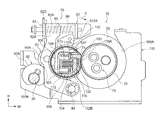
- FIG. 5 is a sectional view illustrating a first state in which the fixing belt is pressed against the heating roll by a pad member and a block member which are used in the fixing device illustrated in FIG. 3 ;
- FIG. 6 is a sectional view illustrating a state where a part near the pad member, the block member, and the heating roll which are illustrated in FIG. 5 is enlarged;
- FIG. 7 is a sectional view taken through a different part from the part through which FIG. 5 is taken and illustrates the parent lever and the block member in a first state illustrated in FIG. 5 ;
- FIG. 8 is a sectional view illustrating a second state where the fixing belt is pressed against the heating roll only by the pad member among the pad member and the block member which are used in the fixing device illustrated in FIG. 3 ;
- FIG. 9 is a sectional view illustrating a state where a part near the pad member, the block member, and the heating roll which are illustrated in FIG. 8 is enlarged;
- FIG. 10 is a sectional view taken through a different part from the part through which FIG. 8 is taken and illustrates the parent lever and the block member in a second state illustrated in FIG. 8 ;
- FIG. 11 is a sectional view illustrating a state where the fixing belt used in the fixing device illustrated in FIG. 3 is separated from the heating roll;
- FIG. 12 is a sectional view taken through a different part from the part through which FIG. 11 is taken and illustrates the parent lever and the block member in a latch release state illustrated in FIG. 11 ;
- FIG. 13 is a schematic view of a modification example of a cam in a fixing device according to a first exemplary embodiment
- FIG. 14 is a sectional view illustrating a fixing device according to a second exemplary embodiment and illustrating the first state where the fixing belt is pressed against the heating roll by the pad member and the block member;
- FIG. 15 is a sectional view illustrating the second state where the fixing belt is pressed against the heating roll only by the pad member among the pad member and the block member of the fixing device illustrated in FIG. 14 ;
- FIG. 16 is a sectional view illustrating a state where the fixing belt of the fixing device illustrated in FIG. 14 is separated from the heating roll;
- FIG. 17 is a sectional view illustrating a fixing device according to a third exemplary embodiment and illustrates the first state where the fixing belt is pressed against the heating roll by the pad member and the block member.
- the direction illustrated by an arrow H is the apparatus height direction
- the direction illustrated by an arrow W is the apparatus width direction
- the direction which is illustrated by an arrow D which is orthogonal to each of the apparatus height direction and the apparatus width direction is the apparatus depth direction (arrow D indicates a near side in the apparatus depth direction).
- an image forming apparatus 10 includes a recording paper accommodating unit 12 which accommodates a recording paper P which is an example of a recording medium, a toner image forming unit 14 , a transport unit 16 , a fixing device 70 , an output unit 20 , and a controller 22 .
- the toner image forming unit 14 is provided with four image forming units 24 Y, 24 M, 24 C, and 24 K, and a transfer unit 26 .
- yellow (Y), magenta (M), cyan (C), and black (K) are examples of toner colors.
- Each of the image forming units 24 Y, 24 M, 24 C, and 24 K is provided with a photoconductor 28 , a charging device 30 , an exposure device 32 , a developing device 34 , and a removing device 36 .
- toner images of each color of yellow (Y), magenta (M), cyan (C), and black (K) are formed on an outer circumferential surface of each photoconductor 28 .
- the photoconductor 28 has a function of holding the toner image developed by the developing device 34 .
- the photoconductor 28 is formed in a cylindrical shape, is provide with a photoconductive layer on a surface thereof, and is driven to rotate in the arrow direction by a driving unit (not illustrated).
- the developing device 34 develops a latent image formed in the photoconductor 28 as the toner image.
- the transfer unit 26 is provided with a transfer belt 38 , a primary transfer roll 40 of each color, a driving roll 42 , and a secondary transfer roll 44 .
- a posture of the transfer belt 38 is determined by four rolls, including the primary transfer roll 40 , a support roll 46 , the driving roll 42 , and a tension applying roll 48 , which are in contact with the inner circumferential surface.
- a cleaning device which is not illustrated is provided on the downstream side of a secondary transfer portion which is in contact with the secondary transfer roll 44 .
- the outer circumferential surface of each photoconductor 28 disposed in each of the image forming units 24 Y, 24 M, 24 C, and 24 K, is in contact with the outer circumferential surface on the lower side of the transfer belt 38 .
- the transport unit 16 is provided with a sending roll which is not illustrated and sends out the recording paper P from the recording paper accommodating unit 12 , and plural transporting roll pairs which are not illustrated along a transporting path, and transports the recording paper P sent out by the sending roll to the secondary transfer portion which is at a position at which the driving roll 42 and the secondary transfer roll 44 oppose each other. Furthermore, the transport unit 16 transports the recording paper P to the fixing device 70 . In the fixing device 70 , the toner image which is secondarily transferred to the recording paper P is fixed to the recording paper P, and further, the recording paper P is transported to the output unit 20 by the transport unit 16 .
- exposure light emitted in accordance with image data of each color from the exposure device 32 is incident on the outer circumferential surface of the photoconductor 28 charged by the charging device 30 , and the latent image which corresponds to the image data of each color is formed on the outer circumferential surface of each photoconductor 28 .
- the latent image formed on the outer circumferential surface of each photoconductor 28 is developed as the toner image of each color by each developing device 34 .
- the toner image of each color of the outer circumferential surface of each photoconductor 28 is primarily transferred to the outer circumferential surface of the transfer belt 38 by each primary transfer roll 40 which opposes each photoconductor 28 .
- the recording paper P is sent out of the recording paper accommodating unit 12 , and is transported to the secondary transfer portion provided with the secondary transfer roll 44 .
- the toner image of each color on the transfer belt 38 is secondarily transferred to the recording paper P.
- the recording paper P to which the toner image is transferred is transported toward the fixing device 70 , is heated in a contact portion between a heating roll 72 and a fixing belt 74 which will be described later, and is pressurized, and the toner image is fixed to the recording paper P, the recording paper P is output to an output unit 20 .
- the fixing device 70 is illustrated in a perspective view, and in FIG. 3 , a state where one end portion side of the fixing device 70 in the longitudinal direction is illustrated in a perspective view.
- the fixing device 70 is provided with the heating roll 72 which is an example of a rotating body, and the fixing belt 74 which is an example of an endless belt that is in contact with or is separated from the heating roll 72 .
- the heating roll 72 and the fixing belt 74 are aligned in the apparatus width direction illustrated by the arrow W.
- the fixing device 70 is provided with a support member 76 and a support unit 78 .
- the support member 76 supports both end portions of the heating roll 72 to be rotatable.
- the support unit 78 supports both end portions of the fixing belt 74 to be rotatable, and relatively moves with respect to the support member 76 to presses the fixing belt 74 against the heating roll 72 .
- the support members 76 are provided in both end portions of the heating roll 72 as a left and right pair, and the support units 78 are provided in both end portions of the fixing belt 74 as a left and right pair (refer to FIG. 2 ).
- the heating roll 72 and the fixing belt 74 are disposed considering the apparatus depth direction illustrated by the arrow D of the image forming apparatus 10 as the shaft direction (longitudinal direction).
- the heating roll 72 has a multilayer structure provided with a thin cylindrical core bar made of a steel material, an elastic layer made of silicone rubber with which the surface of the core bar is coated, and a release layer including a fluororesin with which the surface of the elastic layer is coated.
- a heat source 73 configured with plural halogen lamps (three in the exemplary embodiment) is disposed at an interval with the inner circumferential surface of the heating roll 72 (refer to FIGS. 2 and 5 ).
- the fixing belt 74 has a shape of an endless belt, and the release layer including the fluororesin is provided on the outer circumferential surface of a thin cylindrical base material made of a synthetic resin, such as a polyimide resin or a polyamide-imide resin, as necessary.
- a block member 120 which is an example of a first member and a pad member 122 which is an example of a second member, are provided inside the fixing belt 74 .
- the fixing belt 74 is configured to perform pressurizing by the heating roll 72 nipping the recording paper P (not illustrated), and the toner image on the recording paper P is fixed in the contact portion (nip portion) at which the outer circumferential surface of the heating roll 72 and the outer circumferential surface of the fixing belt 74 is in contact with each other.
- the configuration of the inside of the fixing belt 74 will be described later.
- the support member 76 supports both end portions of the heating roll 72 to be rotatable via a bearing which is not illustrated.
- the support member 76 is supported by a bracket 100 in which an arc-like recessed portion 100 A to which the support member 76 is fitted is formed.
- the support unit 78 is provided with a guide member 102 which guides the fixing belt 74 . Furthermore, the support unit 78 is provided with a child lever 80 and a parent lever 82 .
- the child lever 80 is an example of a first support portion and supports the fixing belt 74 via the guide member 102 .
- the parent lever 82 is an example of a second support portion and supports the child lever 80 to be relatively movable.
- An upper portion 82 A of the parent lever 82 in a plan view of the fixing device 70 is formed in a U shape, and is open toward the support member 76 side of the heating roll 72 .
- An upper portion 80 A of the child lever 80 in a plan view of the fixing device 70 has a U shape, and is open toward the side opposite to the support member 76 .
- the width (width in the apparatus depth direction illustrated by the arrow D) of the child lever 80 is configured to be smaller than the width (width in the apparatus depth direction illustrated by the arrow D) of the parent lever 82 , and the child lever 80 is inserted into the parent lever 82 . In this state, the parent lever 82 and the child lever 80 relatively move.
- the child lever 80 is provided with an inner wall 80 B disposed on the inner side (fixing belt 74 side) in the apparatus depth direction illustrated by the arrow D, and an outer wall 80 C disposed to oppose the outer side (a side opposite to the fixing belt 74 ) of the inner wall 80 B.
- a recessed portion 81 which is recessed in the apparatus width direction (arrow W direction) is formed not to interfere with the fixing belt 74 (refer to FIG. 4 ).
- the parent lever 82 is provided with an inner wall 82 B disposed on the inner side (fixing belt 74 side) in the apparatus depth direction illustrated by the arrow D, and an outer wall 82 C disposed to oppose the outer side (a side opposite to the fixing belt 74 ) of the inner wall 82 B.
- the inner wall 82 B of the parent lever 82 is formed in an L shape not to interfere with the fixing belt 74 (refer to FIG. 4 ).
- the inner wall 80 B and the outer wall 80 C of the child lever 80 are disposed between the inner wall 82 B and the outer wall 82 C of the parent lever 82 , and a shaft portion 84 penetrates a through hole formed in a lower portion of the inner walls 82 B and 80 B and outer walls 80 C and 82 C. Accordingly, the child lever 80 and the parent lever 82 relatively move (in the exemplary embodiment, rotate) around the shaft portion 84 . In other words, the child lever 80 and the parent lever 82 move independently from the support member 76 .
- a hole portion 80 E (refer to FIG. 4 ) is formed, and in a state where a pin member 86 is inserted into the hole portion 80 E, a base end of the pin member 86 is fixed to the wall 80 D (refer to FIGS. 4 and 5 ).
- the shaft direction of the pin member 86 is the direction intersecting the shaft direction of the shaft portion 84 .
- a long hole 82 E is formed (refer to FIG. 3 ).
- the long hole 82 E is formed in the wall 82 D so that a long diameter portion is in the apparatus height direction (H direction).
- the outer diameter of the shaft portion of the pin member 86 is configured to be smaller than a short diameter portion of the long hole 82 E, and in a state where the tip end portion side of the pin member 86 penetrates the long hole 82 E, the pin member 86 can move in the long hole 82 E.
- the tip end portion of the pin member 86 is not fixed to the wall 82 D of the parent lever 82 , and is a free end.
- a spring 96 is attached to the wall 82 D of the parent lever 82 .
- the spring 96 is an example of a second biasing member and biases the wall 80 D of the child lever 80 to the support member 76 side of the heating roll 72 .
- the spring 96 is disposed around the pin member 86 , and in this state, one end of the spring 96 is fixed to the wall 82 D of the parent lever 82 by an attaching tool 88 (refer to FIG. 4 ).
- one pair of projection portions 82 F and 82 G which protrude to the guide member 102 side are provided (refer to FIG. 4 ).
- the projection portions 82 F and 82 G have a plate shape, and the positions of the tip ends of the projection portions 82 F and 82 G are disposed to be parallel to the shaft direction of the fixing belt 74 .
- the block member 120 is fixed to the tip ends of the projection portions 82 F and 82 G of the parent lever 82 by adhesion or the like.
- the parent lever 82 is provided as a left and right pair on both sides in the longitudinal direction of the fixing belt 74 , and the block member 120 bridges between the tip ends of one pair of the left and right projection portions 82 F and 82 G of the parent lever 82 along the longitudinal direction of the fixing belt 74 . Accordingly, the block member 120 is supported by the parent lever 82 in the fixing belt 74 (refer to FIG. 5 ).
- the block member 120 is formed of a synthetic resin.
- the fixing belt 74 is omitted.
- a roll member 90 is disposed, and a shaft portion 90 A of the roll member 90 is supported to be rotatable by the inner wall 82 B and the outer wall 82 C.
- the roll members 90 are respectively provided to one left and right pair of the parent levers 82 .
- a cam 96 is supported by a wall 100 B on the roll member 90 side in the apparatus width direction (arrow W direction) of the bracket 100 , to be rotatable.
- the cam 92 is an example of a switching portion.
- the cams 92 are provided as a left and right pair on both sides of the fixing device 70 in the longitudinal direction, and the left and right pair of cams 92 are configured to be linked to each other by a rotating shaft 94 and to integrally rotate.
- a radius of an outer circumferential surface 92 A from the center portion of the rotating shaft 94 continuously changes in the circumferential direction, and the outer circumferential surface 92 A of the cam 92 is in contact with the outer circumferential surface of the roll member 90 .
- the cam 92 is driven to rotate by a motor (not illustrated) linked to the end portion of the rotating shaft 94 in the shaft direction.
- the parent lever 82 relatively moves in the direction of approaching or being separated from the support member 76 of the heating roll 72 around the shaft portion 84 .
- the guide member 102 is disposed in both end portions of the fixing belt 74 .
- the guide member 102 is provided with a main body portion 102 A disposed along the vertical direction on the outer side of both end portions of the fixing belt 74 in the longitudinal direction, and an arc-like outer guide portion 102 B formed along the outer circumferential surface of both end portions of the fixing belt 74 in the main body portion 102 A (in FIG. 3 , only one end portion of the fixing belt 74 is illustrated, and the other end portion of the fixing belt 74 is omitted).
- the guide member 102 is fixed to the child lever 80 by a fastening tool which is not illustrated. Accordingly, the guide member 102 rotates around the shaft portion 84 integrally with the child lever 80 with respect to the parent lever 82 .
- an ark-like sliding sheet 103 which is disposed along the inner circumferential surface of the fixing belt 74 and allows the fixing belt 74 to slide, is provided.
- the sliding sheets 103 are respectively attached to a first attaching member 104 and a second attaching member 106 which are fixed to the main body portion 102 A of the guide member 102 .
- the first attaching member 104 is a section, but in order to easily grasp the configuration, hatching is omitted.
- the sliding sheet 103 , the first attaching member 104 , and the second attaching member 106 are disposed along the longitudinal direction of the fixing belt 74 .
- the first attaching member 104 is formed in an L shape in a sectional view, and a felt member 108 is fixed to one end portion of the first attaching member 104 by adhesion or the like to be in contact with the inner circumferential surface of the fixing belt 74 .
- Lubricating oil is impregnated into the felt member 108 . When the felt member 108 contacts with the inner circumferential surface of the fixing belt 74 , the lubricating oil is supplied to the inner circumferential surface of the fixing belt 74 .
- a first holding portion 110 formed in an L shape in a sectional view is disposed along the first attaching member 104 , and the first holding portion 110 is fixed to the first attaching member 104 and the main body portion 102 A of the guide member 102 .
- the first holding portion 110 is a section, but in order to easily grasp the configuration, hatching is omitted.
- a hole portion 110 A is formed in one end portion (end portion on the heating roll 72 side) of the first holding portion 110 .
- a second holding portion 112 formed in an L shape in a sectional view is disposed to configure the first holding portion 110 and a rectangular frame body.
- One end portion of the second holding portion 112 is inserted into the hole portion 110 A of the first holding portion 110 , and the other end portion of the second holding portion 112 is in contact with the other end portion of the first holding portion 110 .
- the second holding portion 112 is fixed to the first holding portion 110 .
- a part of the second attaching member 106 is in contact with the outer side of the other end portion of the second holding portion 112 , and the other end portion of the second holding portion 112 is fixed to the second attaching member 106 .
- an attaching portion 106 A having a U shape in a sectional view is formed on the center portion side of the fixing belt 74 , the attaching portion 106 A is disposed to be open to the heating roll 72 side.
- a spring 114 which is an example of a first biasing member is disposed, and one end portion of the spring 114 is fixed to a bottom surface of the attaching portion 106 A.
- a holding portion 116 having an L shape in a sectional view is attached to the other end portion of the spring 114 .
- a recessed surface 116 A is formed toward the heating roll 72 side in the holding portion 116 , and the pad member 122 is fixed to the recessed surface 116 A by adhesion or the like. Accordingly, the pad member 122 is biased to the heating roll 72 side by the spring 114 disposed in the attaching portion 106 A of the second attaching member 106 .
- the second attaching member 106 is fixed to the main body portion 102 A of the guide member 102 , and the pad member 122 is supported to approach and be separated from the main body portion 102 A of the guide member 102 .
- the pad member 122 is formed of a foam resin, such as a silicone resin, and has a softer configuration than that of the block member 120 .
- the pad member 122 has a two-layered structure in which the foam resins having different forming ratios are layered, but the configuration of the pad member 122 can be changed, and for example, may have a single layer structure.
- the pad member 122 is disposed on the upstream side in the transport direction of the recording paper P ( FIG. 1 ) which passes through the contact portion (nip portion) between the heating roll 72 and the fixing belt 74 , and the block member 120 is disposed further on the downstream side in the transport direction of the recording paper P ( FIG. 1 ) than the pad member 122 .
- the pad member 122 is disposed on the upstream side in the transport direction of the recording paper P which passes through the contact portion (nip portion) between the heating roll 72 and the fixing belt 74 with respect to the block member 120 .
- the transporting path of the recording paper P is disposed along the vertical direction
- the pad member 122 is disposed on the lower side of the vertical direction
- the block member 120 is disposed on the upper side of the vertical direction.
- the pad member 122 and the block member 120 are disposed at a position at which the pad member 122 and the block member 120 are near or adjacent to each other.
- the child lever 80 is supported to be rotatable around the shaft portion 84 with respect to the parent lever 82 , and the shaft portion 84 is disposed on the upstream side in the transport direction of the recording paper P with respect to the contact portion between the heating roll 72 and the fixing belt 74 . Therefore, when the child lever 80 rotates around the shaft portion 84 with respect to the parent lever 82 , the block member 120 which is positioned far from the shaft portion 84 is more largely displaced in the direction of approaching or being separated from the heating roll 72 than the pad member 122 which is positioned to be close to the shaft portion 84 .
- the parent lever 82 of the support unit 78 and the heating roll 72 (support member 76 ) are relatively moved in the direction of approaching or being separated from each other.
- FIGS. 5 and 6 when a part having a large radius of the outer circumferential surface 92 A of the cam 92 comes into contact with the roll member 90 , as the parent lever 82 rotates (rotates clockwise illustrated by the arrow A in FIG. 5 ) around the shaft portion 84 , the parent lever 82 relatively moves in the direction of approaching the heating roll 72 . In other words, in FIGS. 5 and 6 , the parent lever 82 moves to a first position that is close to heating roll 72 .
- the cam 92 is configured so as to switch between a first state and a second state by moving the parent lever 82 of the support unit 78 between the first position and the second position.
- the fixing belt 74 In the first state, the fixing belt 74 is pressed against the heating roll 72 by the block member 120 and the pad member 122 (refer to FIGS. 5 and 6 ).
- the fixing belt 74 In the second state, the fixing belt 74 is pressed against the heating roll 72 only by the pad member 122 (refer to FIGS. 8 and 9 ).
- the block member 120 is fixed to the tip ends of the projection portions 82 F and 82 G of the parent lever 82 , and the block member 120 moves to the heating roll 72 side.
- the fixing belt 74 is pressed against the heating roll 72 by the block member 120 and the pad member 122 (refer to FIGS. 5 and 6 ).
- a latch release mode is achieved.
- the parent lever 82 rotates around the shaft portion 84 , the parent lever 82 relatively moves in the direction of being separated from the heating roll 72 .
- the parent lever 82 moves to a third position which is the most separated from the heating roll 72 .
- the child lever 80 is biased to the heating roll 72 side by the spring 96 of the upper portion 82 A of the parent lever 82 , the child lever 80 moves to a position at which the tip end portion (head portion) of the pin member 86 comes into contact with the wall 82 D of the parent lever 82 . In this state, the block member 120 and the pad member 122 are separated from the heating roll 72 .
- the child lever 80 is biased to the heating roll 72 side by the spring 96 of the upper portion 82 A of the parent lever 82 , and the child lever 80 stops at a position at which a load of the spring 96 , a load of the spring 114 , and a pressing force of the block member 120 are balanced with respect to the parent lever 82 .
- the fixing belt 74 is pressed against the heating roll 72 only by the pad member 122 among the block member 120 and the pad member 122 .
- the fixing device 70 As the fixing belt 74 is pressurized to the heating roll 72 only by the pad member 122 in the second state, the length of the spring 114 and a stroke by which the pad member 122 moves are set.
- an operation of the motor which rotates the cam 92 is controlled by the controller 22 .
- the fixing device 70 is configured so that in the first state, the pressing load to the heating roll 72 by the block member 120 and the pad member 122 is switched between the high load and the low load by changing the radius of the outer circumferential surface 92 A of the cam 92 .
- the pressing load increases (high load) at the part having a large radius of the outer circumferential surface 92 A of the cam 92
- the pressing load decreases (low load) at the part having a smaller radius of the high load of the outer circumferential surface 92 A of the cam 92 than that of the part.
- the pressing load to the heating roll 72 by the pad member 122 is configured to change to the high load and the low load.
- the pressing load increases (high load) at the part (a part having a smaller radius than that of the first state) having a large radius of the outer circumferential surface 92 A of the cam 92
- the pressing load decreases (low load) at the part having a smaller radius of the outer circumferential surface 92 A of the cam 92 than that of the part of the high load of the second state.
- the cam 92 is configured to switch the first state and the second state.
- the type of the recording paper P is detected by a sensor which is not illustrated, but the type of the recording paper P may be manually input.
- the cam 92 is switched to the high load in the first state, and when a normal paper (for example, a case of being from 60 g/m2(GSN) to 120 g/m2(GSN)) is used as the recording paper P, the cam 92 is switched to the low load in the first state.
- a thin paper for example, a case of being less than 60 g/m2(GSN)
- a normal paper for example, a case of being from 60 g/m2(GSN) to 120 g/m2(GSN)
- the cam 92 is switched to the high load in the second state, and when an envelope (a case where of a double paper structure) is used as the recording paper P, the cam 92 is switched to the low load in the second state.
- the type of the recording paper P and the switching of the cam 92 are not limited to the above-described configuration, and can be changed.
- the full latch mode is achieved, and the first state is achieved.
- the parent lever 82 rotates around the shaft portion 84 by the cam 92 , the parent lever 82 moves to the first position that is close to the heating roll 72 .
- the spring 96 which biases the child lever 80 to the heating roll 72 side is provided, and the child lever 80 moves in the direction of approaching the heating roll 72 by the spring 96 .
- the child lever 80 stops with respect to the parent lever 82 .
- the pad member 122 is biased to the heating roll 72 side by the spring 114 disposed in the second attaching member 106 of the guide member 102 , and the guide member 102 rotates integrally with the child fever 80 . Accordingly, the fixing belt 74 is pressed against the heating roll 72 by the pad member 122 . Therefore, in the first state, the fixing belt 74 is pressed to the heating roll 72 by the block member 120 and the pad member 122 . In other words, a part at which the fixing belt 74 is pressed against the heating roll 72 by the block member 120 and the pad member 122 becomes the contact portion (nip portion), and as the recording paper P passes through the contact portion, the toner image is fixed onto the recording paper P.
- the fixing device 70 is configured so that in the first state, the pressing load to the heating roll 72 by the block member 120 and the pad member 122 is switched between the high load and the low load by changing the radius of the outer circumferential surface 92 A of the cam 92 .
- the latch release mode is achieved.
- the parent lever 82 rotates around the shaft portion 84 by the cam 92 , the parent lever 82 moves to the third position which is the most separated from the heating roll 72 .
- the child lever 80 is biased to the heating roll 72 side by the spring 96 of the upper portion 82 A of the parent lever 82 , and by the force of the spring 96 , the child lever 80 moves to the position at which the tip end portion (head portion) of the pin member 86 comes into contact with the wall 82 D (refer to FIG. 9 ) of the parent lever 82 .
- the block member 120 fixed to the projection portions 82 F and 82 G of the parent lever 82 is separated from the heating roll 72 .
- the pad member 122 attached to the child lever 80 that is, the second attaching member 106 of the guide member 102 ) via the spring 114 is also separated from the heating roll 72 .
- the part (the part having a radius smaller than that of the first state and a radius larger than that of the latch release state) at which the dimension of the outer circumferential surface 92 A of the cam 92 is set to be the intermediate dimension comes into contact with the roll member 90 , the half latch mode is achieved, and the second state is achieved.
- the parent lever 82 rotates around the shaft portion 84 by the cam 92 , the parent lever 82 moves to the second position (a position that is closer to the heating roll 72 than the third position) which is more separated from the heating roll 72 than the first position.
- the child lever 80 is biased to the heating roll 72 side by the spring 96 of the upper portion 82 A of the parent lever 82 .
- the pad member 122 is biased to the heating roll 72 side by the spring 114 disposed in the second attaching member 106 of the guide member 102 .
- the child lever 80 stops with respect to the parent lever 82 .
- the block member 120 is fixed to the tip ends of the projection portions 82 F and 82 G of the parent lever 82 , and in the second state, the block member 120 moves to the side which is separated from the heating roll 72 .
- the pad member 122 is biased to the heating roll 72 side by the spring 114 provided in the child lever 80 (that is, the second attaching member 106 of the guide member 102 ), and the fixing belt 74 is pressed against the heating roll 72 by the pad member 122 . Therefore, in the second state, the fixing belt 74 is pressed against the heating roll 72 only by the pad member 122 among the block member 120 and the pad member 122 . In other words, the part at which the fixing belt 74 is pressed against the heating roll 72 only by the pad member 122 becomes the contact portion (nip portion), and as the recording paper P passes through the contact portion, the toner image on the recording paper P is fixed.
- the earn 92 switches four types of modes, such as the high load and the low load in the first state, and the high load and the low load in the second state, in accordance with the type of the recording paper P which passes through the contact portion (nip portion) between the heating roll 72 and the fixing belt 74 .
- the pressure to the heating roll 72 of the fixing belt 74 by the pad member 122 and the block member 120 , and the pressure to the heating roll 72 of the fixing belt 74 only by the pad member 122 are switched by a short stroke of the parent lever 82 .
- the load is switched to the appropriate fixing load in accordance with the type of the recording paper P which passes through the contact portion between the heating roll 72 and the fixing belt 74 .
- FIG. 13 a modification example of the cam which is used in the fixing device 70 of the first exemplary embodiment is illustrated in a schematic configuration view.
- cams 132 and 142 which are an example of the switching portion disposed in both end portions in the longitudinal direction of the fixing device 70 are provided.
- the cam 142 is disposed on a front side (D side) in the longitudinal direction of the fixing device 70
- the cam 132 is disposed on a rear side ( ⁇ D side) in the longitudinal direction of the fixing device 70 .
- phases of outer circumferential surfaces 132 A and 142 A are changed in the longitudinal direction of the fixing device 70 .
- the phase of the outer circumferential surface 132 A of the cam 142 at the position at which the recording paper P passes through the contact portion between the heating roll 72 (refer to FIG. 5 ) and the fixing belt 74 (refer to FIG. 5 ), and the phase of the outer circumferential surface 132 A of the cam 132 are changed.
- the first state by changing the phases of the outer circumferential surface 142 A of the cam 142 on the front side (D side) and the phase of the outer circumferential surface 132 A of the cam 132 on the rear side ( ⁇ D side), a bite amount by which the block member 120 bites into the heating roll 72 via the fixing belt 74 is adjusted in the longitudinal direction of the fixing device 70 .
- the bite amount by which the block member 120 bites into the heating roll 72 via the fixing belt 74 on the rear side in the longitudinal direction of the fixing device 70 is adjusted to be greater than that on the front side.
- phase of the outer circumferential surface 142 A of the cam 142 on the front side (D side), and the phase of the outer circumferential surface 132 A of the cam 132 on the rear side ( ⁇ D side), are not limited to the configuration illustrated in FIG. 13 , and may be changed.
- the cam 142 on the front side (D side) and the cam 132 on the rear side ( ⁇ D side) may be reversed to each other, and two cams having a shape different from that of FIG. 13 may be respectively provided.
- the bite amount by which the block member 120 bites into the heating roll 72 via the fixing belt 74 in the longitudinal direction is adjusted.
- the second attaching member 106 is provided in a first holding portion 152 and a second holding portion 154 which are fixed to the main body portion 102 A of the guide member 102 .
- the first holding portion 152 is formed in an L shape in a sectional view, is disposed along the first attaching member 104 , and is fixed to the first attaching member 104 .
- the L-shaped second holding portion 154 is fixed to the first holding portion 152
- the second attaching member 106 is fixed to the second holding portion 154 .
- the first holding portion 152 is a section, and in order to easily grasp the configuration, hatching is omitted.
- a projection portion 156 F (the projection portion on the outer side is not illustrated) which protrudes to the guide member 102 side is provided, and at the tip end of the projection portion 156 F, a plate shaped attaching portion 158 is provided along the longitudinal direction of the fixing belt 74 .
- One end portion of the spring 160 which is an example of a third biasing member is fixed to the attaching portion 158 , and the block member 120 is fixed to the other end portion of the spring 160 . Accordingly, the block member 120 is biased to the heating roll 72 side by the spring 160 provided in the parent lever 82 .
- the full latch mode is achieved, and the first state is achieved.
- the parent lever 82 rotates around the shaft portion 84 by the cam 92 , the parent lever 82 moves to the first position that is close to the heating roll 72 .
- the block member 120 is biased to the heating roll 72 side by the spring 160 provided in the parent lever 82 , and the fixing belt 74 is pressed against the heating roll 72 by the block member 120 .
- the pad member 122 is biased to the heating roll 72 side by the spring 114 supported by the guide member 102 which rotates integrally with the child lever 80 , and the fixing belt 74 is pressed against the heating roll 72 by the pad member 122 . Therefore, in the first state, the fixing belt 74 is pressed to the heating roll 72 by the block member 120 and the pad member 122 .
- the latch release mode is achieved.
- the parent lever 82 rotates around the shaft portion 84 , the parent lever 82 moves to the third position which is the most separated from the heating roll 72 , and the block member 120 and the pad member 122 are separated from the heating roll 72 .
- the part (the part having a radius smaller than that of the first state and a radius larger than that of the latch release state) at which the radius of the outer circumferential surface 92 A of the cam 92 is set to be the intermediate dimension comes into contact with the roll member 90 , the half latch mode is achieved, and the second state is achieved.
- the parent lever 82 rotates around the shaft portion 84 by the cam 92 , the parent lever 82 moves to the second position (a position that is closer to the heating roll 72 than the third position) which is more separated from the heating roll 72 than the first position.
- the block member 120 supported by the parent lever 82 via the spring 160 is separated from the heating roll 72 .
- the pad member 122 is biased to the heating roll 72 side by the spring 114 supported by the guide member 102 that rotates integrally with the child lever 80 , and the fixing belt 74 is pressed against the heating roll 72 by the pad member 122 . Therefore, in the second state, the fixing belt 74 is pressed against the heating roll 72 only by the pad member 122 among the block member 120 and the pad member 122 .
- the spring 160 which biases the block member 120 to the heating roll 72 side is provided in the parent lever 82 . Therefore, compared to a configuration in which the spring 160 is not provided, unevenness (unevenness of the load of the fixing belt 74 in the longitudinal direction and unevenness of the load on the upstream side and on the downstream side of the contact portion) of the load by which the fixing belt 74 is pressed against the heating roll 72 by the block member 120 , is prevented.
- a spring 172 which is an example of the third biasing member is provided between the cam 92 and the roll member 90 , in the cam 92 .
- the spring 172 between the cam 92 and the roll member 90 , in a state where a gap is provided between the outer circumferential surface 92 A of the cam 92 and the circumferential surface of the roll member 90 , the outer circumferential surface 92 A of the cam 92 and the circumferential surface of the roll member 90 oppose to be close to each other.
- the block member 120 is fixed to the tip end of the projection portion 82 F of the parent lever 82 . Accordingly, the block member 120 is biased to the heating roll 72 side by the spring 172 provided between the cam 92 and the roll member 90 .
- the parent lever 82 rotates around the shaft portion 84 by the cam 92 in the first state, the parent lever 82 moves to the first position that is close the heating roll 72 .
- the fixing belt 74 is pressed against the heating roll 72 by the block member 120 .
- the pad member 122 is biased to the heating roll 72 side by the spring 114 supported by the guide member 102 which rotates integrally with the child lever 80 , and the fixing belt 74 is pressed against the heating roll 72 by the pad member 122 . Therefore, in the first state, the fixing belt 74 is pressed to the heating roll 72 by the block member 120 and the pad member 122 .
- the fixing device 170 compared to a configuration in which the spring 172 is not provided, unevenness (unevenness of the load of the fixing belt 74 in the longitudinal direction and unevenness of the load on the upstream side and on the downstream side of the contact portion) of the load by which the fixing belt 74 is pressed against the heating roll 72 by the block member 120 is prevented.
- the cam 92 is used as a switching portion, but the invention is not limited thereto.
- a switching portion such as a cylinder, an actuator, and a lack and pinion, is used, may be employed.
Landscapes
- Physics & Mathematics (AREA)
- General Physics & Mathematics (AREA)
- Fixing For Electrophotography (AREA)
- Resistance Heating (AREA)
Abstract
Description
Claims (12)
Applications Claiming Priority (2)
| Application Number | Priority Date | Filing Date | Title |
|---|---|---|---|
| JP2016-017230 | 2016-02-01 | ||
| JP2016017230A JP6679956B2 (en) | 2016-02-01 | 2016-02-01 | Fixing device and image forming apparatus |
Publications (2)
| Publication Number | Publication Date |
|---|---|
| US20170219971A1 US20170219971A1 (en) | 2017-08-03 |
| US9933733B2 true US9933733B2 (en) | 2018-04-03 |
Family
ID=59387547
Family Applications (1)
| Application Number | Title | Priority Date | Filing Date |
|---|---|---|---|
| US15/245,610 Active US9933733B2 (en) | 2016-02-01 | 2016-08-24 | Fixing device and image forming apparatus having a switching portion |
Country Status (2)
| Country | Link |
|---|---|
| US (1) | US9933733B2 (en) |
| JP (1) | JP6679956B2 (en) |
Families Citing this family (2)
| Publication number | Priority date | Publication date | Assignee | Title |
|---|---|---|---|---|
| US11454908B2 (en) * | 2020-05-28 | 2022-09-27 | Canon Kabushiki Kaisha | Image heating apparatus comprising halogen heater with two glass-covered heating portions |
| JP7543760B2 (en) | 2020-07-30 | 2024-09-03 | ブラザー工業株式会社 | Image forming device |
Citations (2)
| Publication number | Priority date | Publication date | Assignee | Title |
|---|---|---|---|---|
| JP2006126536A (en) | 2004-10-29 | 2006-05-18 | Fuji Xerox Co Ltd | Fixing device and image forming apparatus |
| JP2009163188A (en) | 2008-01-10 | 2009-07-23 | Fuji Xerox Co Ltd | Fixing device |
Family Cites Families (4)
| Publication number | Priority date | Publication date | Assignee | Title |
|---|---|---|---|---|
| JP4306742B2 (en) * | 2007-02-28 | 2009-08-05 | コニカミノルタビジネステクノロジーズ株式会社 | Fixing device |
| JP5533336B2 (en) * | 2010-06-25 | 2014-06-25 | 富士ゼロックス株式会社 | Fixing apparatus and image forming apparatus |
| US9031484B2 (en) * | 2011-06-28 | 2015-05-12 | Kabushiki Kaisha Toshiba | Fuser, image forming apparatus, and image forming method |
| JP2013044773A (en) * | 2011-08-22 | 2013-03-04 | Canon Inc | Image heating device |
-
2016
- 2016-02-01 JP JP2016017230A patent/JP6679956B2/en active Active
- 2016-08-24 US US15/245,610 patent/US9933733B2/en active Active
Patent Citations (2)
| Publication number | Priority date | Publication date | Assignee | Title |
|---|---|---|---|---|
| JP2006126536A (en) | 2004-10-29 | 2006-05-18 | Fuji Xerox Co Ltd | Fixing device and image forming apparatus |
| JP2009163188A (en) | 2008-01-10 | 2009-07-23 | Fuji Xerox Co Ltd | Fixing device |
Also Published As
| Publication number | Publication date |
|---|---|
| JP6679956B2 (en) | 2020-04-15 |
| JP2017138363A (en) | 2017-08-10 |
| US20170219971A1 (en) | 2017-08-03 |
Similar Documents
| Publication | Publication Date | Title |
|---|---|---|
| US9885985B2 (en) | Fixing device and image forming apparatus | |
| US8107864B2 (en) | Separating member, fixing device, and image forming apparatus | |
| US8942612B2 (en) | Image heating apparatus | |
| US8515312B2 (en) | Fixing device and image forming apparatus including same | |
| US7706707B2 (en) | Fixing apparatus | |
| JP6665689B2 (en) | Pressure depressurizing device, fixing device and image forming device | |
| US9207592B2 (en) | Fixing device capable of preventing temperature drop due to heat absorption and image forming apparatus including same | |
| US9568865B2 (en) | Belt device, fixing device, and image forming apparatus | |
| US10795289B2 (en) | Fixing device and image forming apparatus incorporating the same | |
| US12443132B2 (en) | Fixing unit | |
| US8503898B2 (en) | Fixing device and image forming apparatus | |
| US9104149B2 (en) | Fixing device having secured member with radius of curvature at insertion end and image forming apparatus having the same | |
| US10474076B2 (en) | Fixing device and image forming apparatus | |
| US9933733B2 (en) | Fixing device and image forming apparatus having a switching portion | |
| JP6638378B2 (en) | Fixing device and image forming device | |
| US10802424B2 (en) | Fixing device and image forming apparatus | |
| JP5784202B2 (en) | Positioning member and image forming apparatus | |
| US8014712B2 (en) | Fusing device and image forming apparatus having the same | |
| US12259668B2 (en) | Sliding fixing device and image forming apparatus incorporating the same | |
| JP7543760B2 (en) | Image forming device | |
| JP7404893B2 (en) | Fixing device and image forming device | |
| JP2025162321A (en) | Fixing device and image forming apparatus | |
| US9519246B2 (en) | Image forming apparatus having image forming units that vary pressure against developer image carrier |
Legal Events
| Date | Code | Title | Description |
|---|---|---|---|
| AS | Assignment |
Owner name: FUJI XEROX CO., LTD., JAPAN Free format text: ASSIGNMENT OF ASSIGNORS INTEREST;ASSIGNOR:KAMIYA, SHOGO;REEL/FRAME:039526/0891 Effective date: 20160818 |
|
| STCF | Information on status: patent grant |
Free format text: PATENTED CASE |
|
| AS | Assignment |
Owner name: FUJIFILM BUSINESS INNOVATION CORP., JAPAN Free format text: CHANGE OF NAME;ASSIGNOR:FUJI XEROX CO., LTD.;REEL/FRAME:058287/0056 Effective date: 20210401 |
|
| MAFP | Maintenance fee payment |
Free format text: PAYMENT OF MAINTENANCE FEE, 4TH YEAR, LARGE ENTITY (ORIGINAL EVENT CODE: M1551); ENTITY STATUS OF PATENT OWNER: LARGE ENTITY Year of fee payment: 4 |
|
| MAFP | Maintenance fee payment |
Free format text: PAYMENT OF MAINTENANCE FEE, 8TH YEAR, LARGE ENTITY (ORIGINAL EVENT CODE: M1552); ENTITY STATUS OF PATENT OWNER: LARGE ENTITY Year of fee payment: 8 |