US9932926B2 - Injector controlling method using opening duration - Google Patents
Injector controlling method using opening duration Download PDFInfo
- Publication number
- US9932926B2 US9932926B2 US15/368,301 US201615368301A US9932926B2 US 9932926 B2 US9932926 B2 US 9932926B2 US 201615368301 A US201615368301 A US 201615368301A US 9932926 B2 US9932926 B2 US 9932926B2
- Authority
- US
- United States
- Prior art keywords
- injector
- injectors
- time
- opening
- opening duration
- Prior art date
- Legal status (The legal status is an assumption and is not a legal conclusion. Google has not performed a legal analysis and makes no representation as to the accuracy of the status listed.)
- Active
Links
Images


Classifications
-
- F—MECHANICAL ENGINEERING; LIGHTING; HEATING; WEAPONS; BLASTING
- F02—COMBUSTION ENGINES; HOT-GAS OR COMBUSTION-PRODUCT ENGINE PLANTS
- F02D—CONTROLLING COMBUSTION ENGINES
- F02D41/00—Electrical control of supply of combustible mixture or its constituents
- F02D41/30—Controlling fuel injection
- F02D41/38—Controlling fuel injection of the high pressure type
- F02D41/40—Controlling fuel injection of the high pressure type with means for controlling injection timing or duration
-
- F—MECHANICAL ENGINEERING; LIGHTING; HEATING; WEAPONS; BLASTING
- F02—COMBUSTION ENGINES; HOT-GAS OR COMBUSTION-PRODUCT ENGINE PLANTS
- F02D—CONTROLLING COMBUSTION ENGINES
- F02D41/00—Electrical control of supply of combustible mixture or its constituents
- F02D41/02—Circuit arrangements for generating control signals
- F02D41/14—Introducing closed-loop corrections
- F02D41/1401—Introducing closed-loop corrections characterised by the control or regulation method
- F02D41/1402—Adaptive control
-
- F—MECHANICAL ENGINEERING; LIGHTING; HEATING; WEAPONS; BLASTING
- F02—COMBUSTION ENGINES; HOT-GAS OR COMBUSTION-PRODUCT ENGINE PLANTS
- F02D—CONTROLLING COMBUSTION ENGINES
- F02D41/00—Electrical control of supply of combustible mixture or its constituents
- F02D41/20—Output circuits, e.g. for controlling currents in command coils
-
- F—MECHANICAL ENGINEERING; LIGHTING; HEATING; WEAPONS; BLASTING
- F02—COMBUSTION ENGINES; HOT-GAS OR COMBUSTION-PRODUCT ENGINE PLANTS
- F02D—CONTROLLING COMBUSTION ENGINES
- F02D41/00—Electrical control of supply of combustible mixture or its constituents
- F02D41/24—Electrical control of supply of combustible mixture or its constituents characterised by the use of digital means
- F02D41/2406—Electrical control of supply of combustible mixture or its constituents characterised by the use of digital means using essentially read only memories
- F02D41/2425—Particular ways of programming the data
- F02D41/2429—Methods of calibrating or learning
- F02D41/2451—Methods of calibrating or learning characterised by what is learned or calibrated
- F02D41/2464—Characteristics of actuators
- F02D41/2467—Characteristics of actuators for injectors
-
- F—MECHANICAL ENGINEERING; LIGHTING; HEATING; WEAPONS; BLASTING
- F02—COMBUSTION ENGINES; HOT-GAS OR COMBUSTION-PRODUCT ENGINE PLANTS
- F02M—SUPPLYING COMBUSTION ENGINES IN GENERAL WITH COMBUSTIBLE MIXTURES OR CONSTITUENTS THEREOF
- F02M51/00—Fuel-injection apparatus characterised by being operated electrically
- F02M51/005—Arrangement of electrical wires and connections, e.g. wire harness, sockets, plugs; Arrangement of electronic control circuits in or on fuel injection apparatus
-
- F—MECHANICAL ENGINEERING; LIGHTING; HEATING; WEAPONS; BLASTING
- F02—COMBUSTION ENGINES; HOT-GAS OR COMBUSTION-PRODUCT ENGINE PLANTS
- F02M—SUPPLYING COMBUSTION ENGINES IN GENERAL WITH COMBUSTIBLE MIXTURES OR CONSTITUENTS THEREOF
- F02M51/00—Fuel-injection apparatus characterised by being operated electrically
- F02M51/06—Injectors peculiar thereto with means directly operating the valve needle
- F02M51/061—Injectors peculiar thereto with means directly operating the valve needle using electromagnetic operating means
-
- F—MECHANICAL ENGINEERING; LIGHTING; HEATING; WEAPONS; BLASTING
- F02—COMBUSTION ENGINES; HOT-GAS OR COMBUSTION-PRODUCT ENGINE PLANTS
- F02M—SUPPLYING COMBUSTION ENGINES IN GENERAL WITH COMBUSTIBLE MIXTURES OR CONSTITUENTS THEREOF
- F02M65/00—Testing fuel-injection apparatus, e.g. testing injection timing ; Cleaning of fuel-injection apparatus
- F02M65/001—Measuring fuel delivery of a fuel injector
-
- F—MECHANICAL ENGINEERING; LIGHTING; HEATING; WEAPONS; BLASTING
- F02—COMBUSTION ENGINES; HOT-GAS OR COMBUSTION-PRODUCT ENGINE PLANTS
- F02M—SUPPLYING COMBUSTION ENGINES IN GENERAL WITH COMBUSTIBLE MIXTURES OR CONSTITUENTS THEREOF
- F02M65/00—Testing fuel-injection apparatus, e.g. testing injection timing ; Cleaning of fuel-injection apparatus
- F02M65/005—Measuring or detecting injection-valve lift, e.g. to determine injection timing
-
- F—MECHANICAL ENGINEERING; LIGHTING; HEATING; WEAPONS; BLASTING
- F02—COMBUSTION ENGINES; HOT-GAS OR COMBUSTION-PRODUCT ENGINE PLANTS
- F02D—CONTROLLING COMBUSTION ENGINES
- F02D41/00—Electrical control of supply of combustible mixture or its constituents
- F02D41/20—Output circuits, e.g. for controlling currents in command coils
- F02D2041/202—Output circuits, e.g. for controlling currents in command coils characterised by the control of the circuit
- F02D2041/2024—Output circuits, e.g. for controlling currents in command coils characterised by the control of the circuit the control switching a load after time-on and time-off pulses
-
- F—MECHANICAL ENGINEERING; LIGHTING; HEATING; WEAPONS; BLASTING
- F02—COMBUSTION ENGINES; HOT-GAS OR COMBUSTION-PRODUCT ENGINE PLANTS
- F02D—CONTROLLING COMBUSTION ENGINES
- F02D41/00—Electrical control of supply of combustible mixture or its constituents
- F02D41/20—Output circuits, e.g. for controlling currents in command coils
- F02D2041/202—Output circuits, e.g. for controlling currents in command coils characterised by the control of the circuit
- F02D2041/2051—Output circuits, e.g. for controlling currents in command coils characterised by the control of the circuit using voltage control
-
- F—MECHANICAL ENGINEERING; LIGHTING; HEATING; WEAPONS; BLASTING
- F02—COMBUSTION ENGINES; HOT-GAS OR COMBUSTION-PRODUCT ENGINE PLANTS
- F02D—CONTROLLING COMBUSTION ENGINES
- F02D41/00—Electrical control of supply of combustible mixture or its constituents
- F02D41/20—Output circuits, e.g. for controlling currents in command coils
- F02D2041/202—Output circuits, e.g. for controlling currents in command coils characterised by the control of the circuit
- F02D2041/2055—Output circuits, e.g. for controlling currents in command coils characterised by the control of the circuit with means for determining actual opening or closing time
-
- F—MECHANICAL ENGINEERING; LIGHTING; HEATING; WEAPONS; BLASTING
- F02—COMBUSTION ENGINES; HOT-GAS OR COMBUSTION-PRODUCT ENGINE PLANTS
- F02D—CONTROLLING COMBUSTION ENGINES
- F02D41/00—Electrical control of supply of combustible mixture or its constituents
- F02D41/20—Output circuits, e.g. for controlling currents in command coils
- F02D2041/202—Output circuits, e.g. for controlling currents in command coils characterised by the control of the circuit
- F02D2041/2058—Output circuits, e.g. for controlling currents in command coils characterised by the control of the circuit using information of the actual current value
-
- F—MECHANICAL ENGINEERING; LIGHTING; HEATING; WEAPONS; BLASTING
- F02—COMBUSTION ENGINES; HOT-GAS OR COMBUSTION-PRODUCT ENGINE PLANTS
- F02D—CONTROLLING COMBUSTION ENGINES
- F02D41/00—Electrical control of supply of combustible mixture or its constituents
- F02D41/30—Controlling fuel injection
- F02D41/38—Controlling fuel injection of the high pressure type
- F02D2041/389—Controlling fuel injection of the high pressure type for injecting directly into the cylinder
-
- F—MECHANICAL ENGINEERING; LIGHTING; HEATING; WEAPONS; BLASTING
- F02—COMBUSTION ENGINES; HOT-GAS OR COMBUSTION-PRODUCT ENGINE PLANTS
- F02D—CONTROLLING COMBUSTION ENGINES
- F02D2200/00—Input parameters for engine control
- F02D2200/02—Input parameters for engine control the parameters being related to the engine
- F02D2200/06—Fuel or fuel supply system parameters
- F02D2200/0614—Actual fuel mass or fuel injection amount
-
- F—MECHANICAL ENGINEERING; LIGHTING; HEATING; WEAPONS; BLASTING
- F02—COMBUSTION ENGINES; HOT-GAS OR COMBUSTION-PRODUCT ENGINE PLANTS
- F02D—CONTROLLING COMBUSTION ENGINES
- F02D2200/00—Input parameters for engine control
- F02D2200/02—Input parameters for engine control the parameters being related to the engine
- F02D2200/06—Fuel or fuel supply system parameters
- F02D2200/0618—Actual fuel injection timing or delay, e.g. determined from fuel pressure drop
-
- F—MECHANICAL ENGINEERING; LIGHTING; HEATING; WEAPONS; BLASTING
- F02—COMBUSTION ENGINES; HOT-GAS OR COMBUSTION-PRODUCT ENGINE PLANTS
- F02D—CONTROLLING COMBUSTION ENGINES
- F02D41/00—Electrical control of supply of combustible mixture or its constituents
- F02D41/008—Controlling each cylinder individually
- F02D41/0085—Balancing of cylinder outputs, e.g. speed, torque or air-fuel ratio
-
- F—MECHANICAL ENGINEERING; LIGHTING; HEATING; WEAPONS; BLASTING
- F02—COMBUSTION ENGINES; HOT-GAS OR COMBUSTION-PRODUCT ENGINE PLANTS
- F02M—SUPPLYING COMBUSTION ENGINES IN GENERAL WITH COMBUSTIBLE MIXTURES OR CONSTITUENTS THEREOF
- F02M51/00—Fuel-injection apparatus characterised by being operated electrically
- F02M51/06—Injectors peculiar thereto with means directly operating the valve needle
- F02M51/061—Injectors peculiar thereto with means directly operating the valve needle using electromagnetic operating means
- F02M51/0625—Injectors peculiar thereto with means directly operating the valve needle using electromagnetic operating means characterised by arrangement of mobile armatures
- F02M51/0664—Injectors peculiar thereto with means directly operating the valve needle using electromagnetic operating means characterised by arrangement of mobile armatures having a cylindrically or partly cylindrically shaped armature, e.g. entering the winding; having a plate-shaped or undulated armature entering the winding
Definitions
- the present invention relates to an injector controlling method using an opening duration, and more particularly, to a method for controlling an actuation signal of an injector using an opening duration by converting a target fuel quantity of the injector into the opening duration.
- a fuel injection type of a vehicle engine is generally divided into a port injection type and a direct injection type.
- the port injection type is mainly used in a gasoline engine and adopts the way to supply fuel-air mixture to the inside of a cylinder by injecting fuel to an intake port.
- the direction injection type is mainly used in a diesel engine and adopts the way to directly inject fuel to the inside of the cylinder.
- GDI Gasoline Direct Injection
- the GDI engine has injectors respectively mounted on cylinders to inject fuel at high pressure.
- a solenoid of each injector injects fuel into the combustion chamber by opening an injection outlet when receiving an actuation signal from a controller, and then, closes the injection outlet when injection is finished.
- the injectors are different from one another in the time that the injection outlets are closed due to differences in abrasion and deterioration of the injectors, internal friction of needles or internal friction of an amateur and a difference in elastic modulus of a return spring, and hence, the fuel quantity injected by the injector is varied.
- the conventional technologies have adopt the method of controlling the injector by converting the target fuel quantity into an actuation signal through a map in which relationship between the target fuel quantity and the actuation signal for actuating the injector is set.
- the conventional method has several disadvantages in that the injectors are different in the degree of opening from one another even though the same actuation signal is applied to the injectors, in that it is difficult to accurately control the fuel quantity even though various calibrated maps because the injector actuation time and the degree of opening of the injectors are not simply proportional to each other, and in that problems, such as combustion instability and excessive discharge of particulate matters if the quantity of fuel injected is small.
- the present invention has been made in view of the above-mentioned problems occurring in the prior art, and it is an object of the present invention to provide an injector controlling method using an opening duration, which converts a target fuel quantity into an opening duration and sets relationship between the opening duration and an injector actuation signal in order to control the fuel quantity of injectors more accurately.
- an injector controlling method using an opening duration including: a first step of applying actuation signals to a plurality of injectors and securing a time profile of the output voltage; a second step of evaluating the time profile to determine the closing time of the injectors; a third step of learning the opening durations of the injectors based on the closing time; a fourth step of selecting a standard injector out of the injectors; and a fifth step of determining an actuation signal to be inputted into the remaining injectors except the standard injector based on the learned opening duration of the standard injector.
- the output voltage is a self-induced voltage which is created when a current flow is interrupted after the current flow is formed on the injector by the actuation signal.
- the second step includes the steps of finding an inflection point from the time profile of the self-induced voltage and determining the closing time based on the inflection point.
- the inflection point is formed while the self-induced voltage is decayed.
- the third step includes the steps of: determining the opening time based on a current peak value of the actuation signal; determining a time interval between the opening time and the closing time as an opening duration; and storing the determined opening duration.
- the standard injector is selected by comparing the learned opening durations of the plural injectors.
- the standard injector is selected among the injectors having the intermediate value.
- the fifth step includes the steps of: matching the learned opening durations of the injector except the standard injector with the learned opening duration of the standard injector, comparing the actuation signal of the standard injector with the actuation signal of the remaining injectors, and determining the actuation signals of the remaining injectors corresponding with the actuation signal of the standard injector relative to the matched opening duration.
- the injector controlling method further includes a sixth step of applying the actuation signal determined in the fifth step to the remaining injectors in order to control fuel quantities of the injectors.
- the fuel quantity is determined applying the relationship between the learned opening duration of the standard injector and the fuel quantity.
- the fuel quantity is determined applying the relationship between the previously mapped opening duration and the fuel quantity.
- the present invention provides a fuel quantity controlling method of an engine in which a plurality of injectors having solenoid coils are mounted, including the steps of: applying an actuation signal to the solenoid coil of each injector; cutting a flow of current flowing through the solenoid coil when the actuation signal is applied, such that the coil is in a currentless state; detecting a time profile of voltage induced from the coil of the currentless state; determining a closing time of the injector based on the detected time profile; determining an opening time of the injector based on the actuation signal, and learning relationship between an opening duration defined by the opening time and the closing time and the actuation signal; and selecting a standard injector out of the plural injectors, and deciding actuation signals for the remaining injectors except the standard injector based on relationship between the actuation signal of the standard injector and the opening duration.
- the closing time in the closing time determining step is determined based on an inflection point of the time profile.
- the opening duration in the opening duration learning step is defined as a time zone between the opening time and the closing time.
- the present invention provides a control device of an engine which has a plurality of injectors, including: an actuation signal transmitting unit for transmitting actuation signals to the injectors; an output signal receiving unit for receiving output voltage corresponding to the actuation signals from the injectors; and a control unit which secures a time profile of the output voltage and evaluates the time profile to determine a closing time of the injectors, learns relationship between an opening duration defined by the opening time and the closing time and the actuation signal, selecting a standard injector out of the plural injectors, and decides actuation signals for the remaining injectors except the standard injector based on the opening duration of the standard injector.
- the injector controlling method using the opening duration can control the fuel quantity of injectors more accurately by converting the target fuel quantity into the opening duration and setting relationship between the opening duration and an injector actuation signal.
- the present invention has various effects, such as excellent durability, and such effects will be clarified in the following detailed description of the preferred embodiment of the present invention.
- FIG. 1 illustrates relationship between a fuel quantity injected by an injector and actuation time that the injector electrically actuates
- FIG. 2A shows a closed state of the injector
- FIG. 2B shows an opened state of the injector
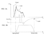
- FIG. 3A is a schematic diagram of a general current operation profile relative to the injector
- FIG. 3B is a view showing the time that an injection outlet of the injector is opened and the time that the injection outlet is closed;
- FIG. 4 is a graph showing a deviation in the degree of opening of injection outlets of injectors respectively mounted on cylinders in a ballistic section;
- FIG. 5 is a graph showing that learning of an opening duration relative to the injectors respectively mounted on the cylinders is carried out and the deviation shown in FIG. 4 is compensated through an accurate and precise control using the result of learning;
- FIG. 6A shows relationship between the opening duration obtained through learning of the opening duration and an actuation signal
- FIG. 6B shows relationship between the fuel quantity and the opening duration
- FIG. 7 is a view showing an injector controlling method according to a preferred embodiment of the present invention.
- FIG. 8 is a view showing a fuel quantity controlling method of an injector according to another preferred embodiment of the present invention.
- FIG. 9 is a control device of an engine according to a further preferred embodiment of the present invention.
- FIG. 1 shows relationship between fuel quantity (m) injected by injectors and actuation time (Ti) for electrically actuating the injectors.
- the X axis is indicated in microseconds ( ⁇ s) and Y axis is indicated in milligrams (mg).
- FIG. 1 illustrates a plurality of profiles showing relationship between the fuel quantity (m) of a plurality of the injectors and actuation time (Ti).
- the fuel quantity (m) injected into a combustion chamber by the injectors may be illustrated into function of the actuation time (Ti) that the injectors are actuated electrically.
- the fuel quantity (m) injected by the injectors may be divided into sections with different complexions according to actuation time (Ti) that the injectors are actuated electrically, and the sections may be generally called a ballistic section (A), a transient section (B) and a non-ballistic section (C).
- the ballistic section (A) means the section where the fuel quantity (m) increases dramatically if there is any change in actuation time (Ti).
- the transient section (B) means the section where the fuel quantity (m) does not change significantly even though the actuation time (Ti) is changed greatly.
- the ballistic section (A) and the transient section (B) are all nonlinear sections.
- the non-ballistic section (C) is a linear section where the actuation time (Ti) and the fuel quantity (m) are in linear relationship. Referring to FIG. 1 , the relation profiles of the injectors do not match with each other in the nonlinear sections but match with each other in the linear section.
- the actuation time (Ti) that the injectors are actuated electrically may correspond with an actuation signal (Ti) applied to the injectors by a controller or actuation time (Ti) that an electric signal is applied to the injectors in order to actuate the injectors.
- the actuation signal (Ti) for instance, is inputted into the injectors in the form of a PWM control signal.
- the actuation time (Ti) that the injectors are actuated electrically will be described as the actuation signal (Ti) applied to the injectors.
- FIGS. 2A and 2B are a schematic diagram showing the basic structure of the injector.
- FIG. 2A shows a closed state of the injector
- FIG. 2B shows an opened state of the injector
- the injector 100 includes: a valve 120 for opening and closing an injection outlet 110 ; a needle 130 of which the end is connected with the valve 120 ; an amateur 140 which is combined with the needle 130 so that the needle 130 makes a rectilinear motion; a magnetic member 150 which is arranged to surround the amateur 140 and forms a route of an electromagnetic field; a solenoid coil 160 which forms a solenoid magnetic field; and a return spring 170 for returning the needle 130 and the amateur 140 moved.
- the solenoid coil 160 is electrically connected with a control unit (not shown) by a wire harness 180 to receive a control signal.
- FIG. 2B shows a state where the injection outlet 110 is opened when the amateur, the needle and the valve are moved upwardly.
- FIG. 3A is a schematic diagram of a general current operation profile relative to the injector
- FIG. 3B shows the time that the injection outlet of the injector is opened and the time that the injection outlet is closed.
- the X axis indicates time (t) and the Y axis indicates intensity of current (I) or voltage (V).
- the thick line indicates a time profile relative to the current (I) and the thin line indicates a time profile relative to voltage (V).
- FIG. 3B shows the time (P) that the injection outlet 110 is opened while the valve of the injector is lifted and delayed mechanically and the time (Q) that the valve 120 is seated and the injection outlet 110 is closed.
- FIG. 3B shows that the valve 120 is rapidly accelerated and opened at the opening time (P), maintains the opened state, and then, is closed at the closing time.
- the opening time (P) corresponds to just short of the maximum current value (I_peak) of the time profile relative to the current (I)
- the closing time (Q) correspond to the position of an inflection point (I_point) of the time profile relative to voltage (V).
- the control unit for controlling the opening time (P) and the closing time (Q) of the injector 100 transfers a control signal to the injector 100 to open or close the injection outlet 110 of the injector 100 .
- V_boost boost voltage
- I_peak maximum current value
- a start point of the electrical actuation of the injector 100 is determined while the applied boost voltage (V_boost) reaches the maximum current value (I_peak), and the start point of the electrical actuation may be the opening time (P) of the injection outlet 110 of the injector 100 .
- the opening time (P) of the injection outlet 110 is the time that the electric signal is inputted to the injector 100 and the needle 130 is lifted due to the sudden acceleration, the injectors 100 respectively mounted on the cylinders are all the same or similar. Therefore, in the present invention, the opening time (P) of the injection outlet 110 of the injector 100 will not be mentioned. However, even though the opening time (P) is not mentioned, the scope of the patent right in a case that the opening time (P) of the injection outlet 110 is varied is not excluded.
- self-induced voltage (V) is formed in the solenoid coil 160 of a currentless state, and the self-induced voltage (V) causes a flow of current passing through the solenoid coil 160 and the flow of current creates self-induced voltage (V) while reducing the magnetic field.
- the self-induced voltage (V) is indicated as negative voltage (V) in FIG. 3A , and is converged to 0 bolt (V) as time goes by.
- the injection outlet 110 of the injector 100 is closed by restoring force caused by elastic force of the return spring 170 and fuel pressure.
- the inflection point (I_point) may be formed at the time profile relative to voltage (V), and the time that the inflection point (I_point) is formed may be the closing time (Q) of the injection outlet 110 of the injector 100 .
- the opening duration corresponds to a period of time that the injector 100 is opened, means a time interval during injection of fuel, and may be defined as a time interval between the opening time (P) and the closing time (Q) of the injector 100 .
- the opening time points (P) of all of the injectors 100 respectively mounted on the cylinders are the same or similar but the closing time points (Q) are varied, learning of the closing time (Q) corresponding to the actuation signal (Ti) may be learning of the opening duration.
- FIG. 4 is a graph showing a deviation in the degree of opening of the injection outlets of the injectors respectively mounted on the cylinders in a ballistic section.
- the X axis indicates an axis of time (t) indicated in microseconds ( ⁇ s)
- the Y axis indicates a lifted level of the needles 130 of the injectors indicated in micrometers ( ⁇ m).
- FIG. 5 is a graph showing that learning of an opening duration relative to the injectors respectively mounted on the cylinders is carried out and the deviation shown in FIG. 4 is compensated through an accurate and precise control using the result of learning.
- the injectors 100 respectively mounted on the cylinder are divided into a minimum injector 100 , a norminal injector 100 and a maximum injector according to the fuel quantity injected by the injectors 100 when the same actuation signals (Ti) are applied to the injectors 100 .
- a standard injector 100 the norminal injector 100 is selected in the present invention. Relationship between the actuation signal (Ti) to the standard injector 100 is determined and mapped. After that, in order to output the opening duration identical with the opening duration of the standard injector 100 , the actuation signals (Ti) of other injectors 100 are respectively determined such that the opening durations of all injectors 100 can be outputted equally.
- relationship between the actuation signals (Ti) of all injectors 100 and the opening durations is determined and mapped (See FIG. 6A ), and then the actuation signals (Ti) of the injectors 100 except the standard injector 100 to output opening durations which are the same or similar with the opening duration of the standard injector 100 , so that the opening durations of all injectors 100 can coincide with one another.
- FIG. 6A shows relationship between the opening duration obtained through learning of the opening duration and an actuation signal.
- the profile shows that the actuation signals (Ti) corresponding to a plurality of previously set learning points are applied to the injector 100 , the inflection point (I_point) is searched on the time profile of the output voltage (V) and the closing time (Q) of the injector 100 , namely, the opening duration is determined and mapped.
- FIG. 6A shows that the relationship between the opening duration and the actuation signal (Ti) is differentiated into a ballistic section (A), a transient section (B) and a non-ballistic section (C), and that the relationship between the opening duration and the actuation signal (Ti) is very similar with the relationship between the fuel quantity (m) and the actuation signal (Ti). Such similarity will be described later referring to FIG. 6B .
- FIG. 6B shows relationship between the fuel quantity and the opening duration.
- the opening duration is the fuel injection period of time, it directly has an influence on the fuel quantity (m) injected into the combustion chamber. Therefore, the fuel quantity (m) injected by the injector 100 may show a little off-set in the relationship with the opening duration, but is in a linear relation. Therefore, when the relationship between the fuel quantity (m) and the opening duration is mapped (See FIG. 6B ) and the relationship between the opening duration and the actuation signal (Ti) is mapped (See FIG. 6A ), the controller can select and output the actuation signal (Ti) corresponding to an operator's desired fuel quantity.
- FIG. 7 is a view showing an injector controlling method according to a preferred embodiment of the present invention.
- the injector controlling method is based on the opening duration, and includes: a first step (S 100 ) of applying actuation signals (Ti) to a plurality of injectors 100 and securing a time profile of the output voltage (V); a second step (S 110 ) of evaluating the time profile to determine the closing time (Q) of the injectors 100 ; a third step (S 120 ) of learning the opening durations of the injectors 100 based on the closing time (Q); a fourth step (S 130 ) of selecting a standard injector 100 out of the injectors 100 ; and a fifth step (S 140 ) of determining an actuation signal (Ti) to be inputted into the remaining injectors 100 except the standard injector 100 based on the learned opening duration of the standard injector 100 .
- time profile of the output voltage (V) may show an aspect that intensity of the output voltage (V) is varied as time goes by.
- the output voltage (V) in the first step (S 100 ) may be a self-induced voltage (V) which is created when a current flow is interrupted after the current flow is formed on the injector 100 by the actuation signal (Ti).
- the output voltage (V) may be the self-induced voltage (V) formed by interruption of external power source after the current flow is formed when the external power source is supplied to the solenoid coil 160 of the injector 100 .
- to determine the closing time (Q) of the injector 100 by evaluating the time profile may mean to find an inflection point (I_point) from the time profile of the self-induced voltage (V) and determine the closing time (Q) based on the inflection point (I_point) according to embodiments.
- the inflection point (I_point) may be formed while the self-induced voltage (V) is decayed in the time profile of the self-induced voltage (V), and the point where the corresponding inflection point (I_point) is formed may be determined as the closing time (Q).
- the second step (S 110 ) may include a process of finding the inflection point (I_point) from the time profile by evaluating the time profile of the output voltage (V) and determining the closing time (Q) based on the inflection point (I_point).
- the standard injector 100 may be selected among the injectors 100 , but according to embodiments, may be selected by comparing the learned opening durations of the injectors 100 . In detail, when the degree of opening corresponding to the learned opening durations of the injectors 100 is divided into a maximum value, an intermediate value and a minimum value, the standard injector 100 may be selected among the injectors 100 having the intermediate value.
- the fuel quantity (m) corresponding to the opening duration may be selected through the relationship between the fuel quantity (m) and the opening duration, the injectors having the maximum value, the intermediate value and the minimum value may correspond with the maximum injector 100 , the norminal injector 100 and the minimum injector 100 .
- the actuation signals (Ti) to be inputted when the remaining injectors 100 are controlled may be determined through the steps of matching the learned opening durations of the injector 100 except the standard injector 100 with the learned opening duration of the standard injector 100 , comparing the actuation signal (Ti) of the standard injector 100 with the actuation signal (Ti) of the remaining injectors 100 , and determining the actuation signals (Ti) of the remaining injectors 100 corresponding with the actuation signal (Ti) of the standard injector 100 .
- the injector controlling method may further include a sixth step (S 150 ) of applying the actuation signal (Ti) determined in the fifth step (S 140 ) to the remaining injectors 100 in order to control fuel quantities (m) of the injectors 100 .
- the fuel quantity (m) may be determined applying the relationship between the previously mapped opening duration and the fuel quantity (m).
- the fuel quantity (m) may be determined applying the relationship between the learned opening duration of the standard injector 100 and the fuel quantity (m).
- the relationship between the learned opening duration of the standard injector 100 and the fuel quantity (m) may be previously mapped.
- FIG. 8 is a view showing a fuel quantity controlling method of an injector according to another preferred embodiment of the present invention.
- the fuel quantity controlling method of the injector 100 for controlling fuel quantity of an engine in which a plurality of injectors 100 respectively having solenoid coils 160 are mounted includes the steps of: (S 200 ) applying an actuation signal (Ti) to the solenoid coil 160 of each injector 100 ; (S 210 ) cutting a flow of current flowing through the solenoid coil 160 when the actuation signal (Ti) is applied, such that the coil is in a currentless state; (S 220 ) detecting a time profile of voltage (V) induced from the coil of the currentless state; (S 230 ) determining a closing time (Q) of the injector 100 based on the detected time profile; (S 240 ) determining an opening time (P) of the injector 100 based on the actuation signal (Ti), and learning relationship between an opening duration defined by the opening time (P) and the closing time (Q) and the actuation signal (Ti); and (S 250 ) selecting a standard
- the closing time (Q) in the closing time determining step (S 230 ) may be determined based on an inflection point (I_point) of the time profile.
- the opening duration in the opening duration learning step (S 240 ) may be defined as a time zone between the opening time (P) and the closing time (Q).
- FIG. 9 is a control device of an engine according to a further preferred embodiment of the present invention.
- the control device 200 of the engine which has a plurality of injectors 100 , includes: an actuation signal transmitting unit 220 for transmitting actuation signals (Ti) to the injectors 100 ; an output signal receiving unit 230 for receiving output voltage (V) corresponding to the actuation signals (Ti) from the injectors 100 ; and a control unit 210 , which secures a time profile of the output voltage (V) and evaluates the time profile to determine a closing time (Q) of the injectors 100 , learns relationship between an opening duration defined by the opening time (P) and the closing time (Q) and the actuation signal (Ti), selecting a standard injector 100 out of the plural injectors 100 , and decides actuation signals (Ti) for the remaining injectors 100 except the standard injector 100 based on the opening duration of the standard injector 100 .
Landscapes
- Engineering & Computer Science (AREA)
- Chemical & Material Sciences (AREA)
- Combustion & Propulsion (AREA)
- Mechanical Engineering (AREA)
- General Engineering & Computer Science (AREA)
- Physics & Mathematics (AREA)
- Electromagnetism (AREA)
- Electrical Control Of Air Or Fuel Supplied To Internal-Combustion Engine (AREA)
- Oil, Petroleum & Natural Gas (AREA)
Abstract
Description
Claims (16)
Applications Claiming Priority (2)
| Application Number | Priority Date | Filing Date | Title |
|---|---|---|---|
| KR10-2015-0173470 | 2015-12-07 | ||
| KR1020150173470A KR101806354B1 (en) | 2015-12-07 | 2015-12-07 | Injection Control Method Using Opening Duration |
Publications (2)
| Publication Number | Publication Date |
|---|---|
| US20170175666A1 US20170175666A1 (en) | 2017-06-22 |
| US9932926B2 true US9932926B2 (en) | 2018-04-03 |
Family
ID=58722645
Family Applications (1)
| Application Number | Title | Priority Date | Filing Date |
|---|---|---|---|
| US15/368,301 Active US9932926B2 (en) | 2015-12-07 | 2016-12-02 | Injector controlling method using opening duration |
Country Status (4)
| Country | Link |
|---|---|
| US (1) | US9932926B2 (en) |
| KR (1) | KR101806354B1 (en) |
| CN (1) | CN106917692B (en) |
| DE (1) | DE102016224326B4 (en) |
Families Citing this family (13)
| Publication number | Priority date | Publication date | Assignee | Title |
|---|---|---|---|---|
| DE102014208753B4 (en) * | 2014-05-09 | 2016-03-31 | Continental Automotive Gmbh | Determination of parameter values for a fuel injector |
| JP2017106354A (en) * | 2015-12-08 | 2017-06-15 | 株式会社デンソー | Control device |
| KR20180067335A (en) | 2016-12-12 | 2018-06-20 | 현대오트론 주식회사 | Method for defining learning area of injector opening duration control |
| KR20180069942A (en) * | 2016-12-15 | 2018-06-26 | 현대자동차주식회사 | Control method for injector of vehicle |
| US10273923B2 (en) * | 2016-12-16 | 2019-04-30 | GM Global Technology Operations LLC | Systems and methods for controlling fluid injections |
| DE102017116379A1 (en) * | 2017-07-20 | 2019-01-24 | Liebherr-Components Deggendorf Gmbh | Device for condition detection of an injector |
| KR101957516B1 (en) * | 2017-11-23 | 2019-03-12 | 현대오트론 주식회사 | Injector drive time control method by area |
| KR101967456B1 (en) * | 2017-12-01 | 2019-04-09 | 현대오트론 주식회사 | Injector failure diagnosis method using injector closing time detection value |
| KR102233163B1 (en) * | 2019-12-13 | 2021-03-29 | 주식회사 현대케피코 | Injector control method of vehicle and control apparatus thereof |
| EP3954888A1 (en) * | 2020-08-12 | 2022-02-16 | Sonplas GmbH | Method for identifying an event and inspection system for inspecting a component |
| KR102619606B1 (en) * | 2021-09-30 | 2023-12-28 | 주식회사 현대케피코 | Fuel injection valve and operating method for therefor |
| DE102023210453A1 (en) * | 2023-10-24 | 2025-04-24 | Vitesco Technologies GmbH | Method, control device, computer program product and fuel injection device for operating a fuel injector of an internal combustion engine |
| CN118934314B (en) * | 2024-08-23 | 2025-10-24 | 潍柴动力股份有限公司 | Fuel injection controller, control method and system |
Citations (12)
| Publication number | Priority date | Publication date | Assignee | Title |
|---|---|---|---|---|
| US20110251808A1 (en) * | 2010-04-07 | 2011-10-13 | Gabriele Serra | Method for determining the closing time of an electromagnetic fuel injector |
| US20120116702A1 (en) * | 2009-07-10 | 2012-05-10 | Johannes Beer | Determining the closing time of a fuel injection valve based on evaluating the actuation voltage |
| US20130104636A1 (en) * | 2010-04-26 | 2013-05-02 | Johannes Beer | Electric actuation of a valve based on knowledge of the closing time of the valve |
| KR20130119934A (en) | 2010-10-14 | 2013-11-01 | 콘티넨탈 오토모티브 게엠베하 | Method for determining the opening point in time of a fuel injector |
| JP2014218981A (en) | 2013-05-10 | 2014-11-20 | 株式会社デンソー | Fuel injection valve control device |
| JP2015135102A (en) | 2013-10-29 | 2015-07-27 | コンチネンタル オートモーティブ システムズ インコーポレイテッドContinental Automotive Systems, Inc. | Direct injection solenoid injector opening time detection |
| US20150226148A1 (en) * | 2012-09-24 | 2015-08-13 | Continental Automotive Gmbh | Electric Actuation of a Valve Based on Knowledge of the Closing Point and Opening Point of the Valve |
| JP2015172346A (en) | 2014-03-12 | 2015-10-01 | 日立オートモティブシステムズ株式会社 | Controller |
| US20160138511A1 (en) * | 2013-07-10 | 2016-05-19 | Hitachi Automotive Systems, Ltd. | Control device for internal combustion engine |
| US20160237937A1 (en) * | 2013-09-25 | 2016-08-18 | Hitachi Automotive Systems, Ltd. | Drive Device for Fuel Injection Device |
| US20160281629A1 (en) * | 2015-03-24 | 2016-09-29 | Keihin Corporation | Control device for fuel injection valve |
| US20170022928A1 (en) * | 2015-07-21 | 2017-01-26 | Hyundai Motor Company | Control method of fuel injection injector and the control system thereof |
Family Cites Families (6)
| Publication number | Priority date | Publication date | Assignee | Title |
|---|---|---|---|---|
| US6237567B1 (en) | 1998-02-18 | 2001-05-29 | Isuzu Motors Limited | Fuel-injection system for engine |
| DE102005032087A1 (en) | 2005-07-08 | 2007-01-18 | Siemens Ag | Method of controlling fuel injection valve for motor vehicle internal combustion (IC) engine, involves determining closing time of nozzle needle, then determining control period for control drive of switching valve based on closing time |
| JP4492532B2 (en) | 2005-12-26 | 2010-06-30 | 株式会社デンソー | Fuel injection control device |
| DE102009003212A1 (en) | 2009-05-19 | 2010-11-25 | Robert Bosch Gmbh | Method and control device for operating an injection valve |
| DE102009027311A1 (en) * | 2009-06-30 | 2011-01-05 | Robert Bosch Gmbh | Method for operating an internal combustion engine |
| JP2015169079A (en) * | 2014-03-05 | 2015-09-28 | 本田技研工業株式会社 | Fuel injection control device for internal combustion engine |
-
2015
- 2015-12-07 KR KR1020150173470A patent/KR101806354B1/en active Active
-
2016
- 2016-12-02 US US15/368,301 patent/US9932926B2/en active Active
- 2016-12-07 CN CN201611117366.2A patent/CN106917692B/en active Active
- 2016-12-07 DE DE102016224326.8A patent/DE102016224326B4/en active Active
Patent Citations (13)
| Publication number | Priority date | Publication date | Assignee | Title |
|---|---|---|---|---|
| US20120116702A1 (en) * | 2009-07-10 | 2012-05-10 | Johannes Beer | Determining the closing time of a fuel injection valve based on evaluating the actuation voltage |
| KR20120052978A (en) | 2009-07-10 | 2012-05-24 | 콘티넨탈 오토모티브 게엠베하 | Determining the closing time of a fuel injection valve based on evaluating the actuation voltage |
| US20110251808A1 (en) * | 2010-04-07 | 2011-10-13 | Gabriele Serra | Method for determining the closing time of an electromagnetic fuel injector |
| US20130104636A1 (en) * | 2010-04-26 | 2013-05-02 | Johannes Beer | Electric actuation of a valve based on knowledge of the closing time of the valve |
| KR20130119934A (en) | 2010-10-14 | 2013-11-01 | 콘티넨탈 오토모티브 게엠베하 | Method for determining the opening point in time of a fuel injector |
| US20150226148A1 (en) * | 2012-09-24 | 2015-08-13 | Continental Automotive Gmbh | Electric Actuation of a Valve Based on Knowledge of the Closing Point and Opening Point of the Valve |
| JP2014218981A (en) | 2013-05-10 | 2014-11-20 | 株式会社デンソー | Fuel injection valve control device |
| US20160138511A1 (en) * | 2013-07-10 | 2016-05-19 | Hitachi Automotive Systems, Ltd. | Control device for internal combustion engine |
| US20160237937A1 (en) * | 2013-09-25 | 2016-08-18 | Hitachi Automotive Systems, Ltd. | Drive Device for Fuel Injection Device |
| JP2015135102A (en) | 2013-10-29 | 2015-07-27 | コンチネンタル オートモーティブ システムズ インコーポレイテッドContinental Automotive Systems, Inc. | Direct injection solenoid injector opening time detection |
| JP2015172346A (en) | 2014-03-12 | 2015-10-01 | 日立オートモティブシステムズ株式会社 | Controller |
| US20160281629A1 (en) * | 2015-03-24 | 2016-09-29 | Keihin Corporation | Control device for fuel injection valve |
| US20170022928A1 (en) * | 2015-07-21 | 2017-01-26 | Hyundai Motor Company | Control method of fuel injection injector and the control system thereof |
Also Published As
| Publication number | Publication date |
|---|---|
| US20170175666A1 (en) | 2017-06-22 |
| CN106917692A (en) | 2017-07-04 |
| CN106917692B (en) | 2020-06-05 |
| DE102016224326A1 (en) | 2017-06-08 |
| KR20170067062A (en) | 2017-06-15 |
| DE102016224326B4 (en) | 2022-08-11 |
| KR101806354B1 (en) | 2018-01-10 |
Similar Documents
| Publication | Publication Date | Title |
|---|---|---|
| US9932926B2 (en) | Injector controlling method using opening duration | |
| EP2450552B1 (en) | Control system of internal combustion engine | |
| US9376982B2 (en) | Control apparatus for fuel injector | |
| US10072596B2 (en) | Control unit for a fuel injector | |
| CN102272436B (en) | Method for operating a fuel injection system | |
| US20140069390A1 (en) | Fuel injection controller | |
| US8996280B2 (en) | Method for operating a fuel injector of an internal combustion engine, and control device for an internal combustion engine | |
| US7377265B2 (en) | Injector driver and drive method for the same | |
| Lu et al. | Impact of control methods on dynamic characteristic of high speed solenoid injectors | |
| KR101957516B1 (en) | Injector drive time control method by area | |
| US7743748B2 (en) | Method of controlling the operation of a solenoid | |
| KR20170064411A (en) | Learning Method for Closing Time of An Injector | |
| WO2016170739A1 (en) | Fuel injection control device | |
| Xiong et al. | An intelligent dual-voltage driving method and circuit for a common rail injector for heavy-duty diesel engines | |
| US20100300412A1 (en) | Method for Optimizing Flow Performance of a Direct Injection Fuel Injector | |
| CN112392621B (en) | Method and device for knowing the opening time of an injector of a vehicle engine | |
| CN109555614B (en) | Method for calibrating a force or pressure sensor | |
| US20170350356A1 (en) | Injector for injecting a fluid, use of an injector and method for manufacturing an injector | |
| JP6515777B2 (en) | Fuel injection device | |
| US10047680B2 (en) | Detecting actuation of air flow control valve of internal combustion engine and corresponding control thereof | |
| KR101786990B1 (en) | Injecter Control Method for GDI Engine | |
| KR101787037B1 (en) | Injection Control Method When Learning An Injector Closing Time and Injection Control System thereof | |
| Steinbrecher et al. | Improved fuel metering for port fuel injection by controlled valve operation | |
| KR101744732B1 (en) | Fault Diagnosis Based on Output Voltage of An Injector | |
| KR101826691B1 (en) | Compensation Method for Closing Time of Injector |
Legal Events
| Date | Code | Title | Description |
|---|---|---|---|
| AS | Assignment |
Owner name: HYUNDAI AUTRON CO., LTD., KOREA, REPUBLIC OF Free format text: ASSIGNMENT OF ASSIGNORS INTEREST;ASSIGNORS:KIM, YONGHA;KIM, YOUNGJAE;CHO, HYUNJAE;REEL/FRAME:040733/0729 Effective date: 20161129 |
|
| STCF | Information on status: patent grant |
Free format text: PATENTED CASE |
|
| AS | Assignment |
Owner name: HYUNDAI KEFICO CORPORATION, KOREA, REPUBLIC OF Free format text: ASSIGNMENT OF ASSIGNORS INTEREST;ASSIGNOR:HYUNDAI AUTRON CO., LTD.;REEL/FRAME:055092/0734 Effective date: 20210125 |
|
| MAFP | Maintenance fee payment |
Free format text: PAYMENT OF MAINTENANCE FEE, 4TH YEAR, LARGE ENTITY (ORIGINAL EVENT CODE: M1551); ENTITY STATUS OF PATENT OWNER: LARGE ENTITY Year of fee payment: 4 |
|
| MAFP | Maintenance fee payment |
Free format text: PAYMENT OF MAINTENANCE FEE, 8TH YEAR, LARGE ENTITY (ORIGINAL EVENT CODE: M1552); ENTITY STATUS OF PATENT OWNER: LARGE ENTITY Year of fee payment: 8 |