US9930148B2 - Roadside sign controller and dynamic message sign system - Google Patents
Roadside sign controller and dynamic message sign system Download PDFInfo
- Publication number
- US9930148B2 US9930148B2 US15/291,611 US201615291611A US9930148B2 US 9930148 B2 US9930148 B2 US 9930148B2 US 201615291611 A US201615291611 A US 201615291611A US 9930148 B2 US9930148 B2 US 9930148B2
- Authority
- US
- United States
- Prior art keywords
- ntcip
- sign
- roadside
- controller
- signal
- Prior art date
- Legal status (The legal status is an assumption and is not a legal conclusion. Google has not performed a legal analysis and makes no representation as to the accuracy of the status listed.)
- Active
Links
Images


Classifications
-
- H—ELECTRICITY
- H04—ELECTRIC COMMUNICATION TECHNIQUE
- H04L—TRANSMISSION OF DIGITAL INFORMATION, e.g. TELEGRAPHIC COMMUNICATION
- H04L69/00—Network arrangements, protocols or services independent of the application payload and not provided for in the other groups of this subclass
- H04L69/16—Implementation or adaptation of Internet protocol [IP], of transmission control protocol [TCP] or of user datagram protocol [UDP]
- H04L69/163—In-band adaptation of TCP data exchange; In-band control procedures
-
- G—PHYSICS
- G08—SIGNALLING
- G08G—TRAFFIC CONTROL SYSTEMS
- G08G1/00—Traffic control systems for road vehicles
- G08G1/07—Controlling traffic signals
- G08G1/081—Plural intersections under common control
-
- G—PHYSICS
- G08—SIGNALLING
- G08G—TRAFFIC CONTROL SYSTEMS
- G08G1/00—Traffic control systems for road vehicles
- G08G1/09—Arrangements for giving variable traffic instructions
- G08G1/095—Traffic lights
-
- H—ELECTRICITY
- H04—ELECTRIC COMMUNICATION TECHNIQUE
- H04L—TRANSMISSION OF DIGITAL INFORMATION, e.g. TELEGRAPHIC COMMUNICATION
- H04L49/00—Packet switching elements
- H04L49/35—Switches specially adapted for specific applications
Definitions
- the present invention relates generally to the field of roadside signals and roadside signal controllers.
- the roadside signals are dynamic message signs common to the transportation industry.
- One embodiment of the invention relates to a roadside signal system including a controller having a central network interface configured to interconnect with a central network.
- the controller is configured to receive and send National Transportation Communications for Intelligent Transportation Systems Protocol (“NTCIP”) compliant transmissions.
- NTCIP National Transportation Communications for Intelligent Transportation Systems Protocol
- the roadside signal system also includes a plurality of signs connected to controller, and each sign is configured to send and receive NTCIP compliant transmissions.
- the controller is further configured to route NTCIP compliant transmissions received through the central network interface to one of the plurality of signs, and to send from the central network interface to the central network NTCIP compliant transmissions received from one of the plurality of signs.
- the roadside signal system includes a signal forwarding unit having a central network interface configured to interconnect with a central network.
- the signal forwarding unit is configured to receive and send NTCIP compliant transmissions.
- the roadside signal system also includes a cabinet-level instrument connected to the signal forwarding unit and a cabinet-level status indicator connected to the signal forwarding unit.
- the signal forwarding unit is configured to receive a status indicator signal from the cabinet-level instrument, convert that signal into a NTCIP compliant transmission, and send the converted signal out to the central network from the central network interface.
- the signal forwarding unit is further configured to receive though the central network interface a NTCIP compliant status transmission, and output that transmission to the cabinet-level status indicator.
- Another embodiment of the invention relates to a roadside signal controller for controlling communications to a plurality of electronic road signs including a plurality of sign connectors configured to interconnect with a plurality of electronic road signs and pass-through NTCIP compliant transmissions.
- the controller also includes a central network connector, which is configured to interconnect with a central network and pass-through NTCIP compliant transmissions.
- the controller further includes a router that is coupled to the plurality of sign connectors and the central network connector. The router is configured to route NTCIP compliant transmissions received at the central network connector to a sign connector of the plurality of sign connectors and route NTCIP compliant transmissions received at the plurality of sign connectors to the central network connector.
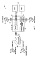
- FIG. 1 is a diagram of an embodiment of the roadside signal system
- FIG. 2 is an interior schematic view of an embodiment of the roadside signal
- FIG. 3 is an interior schematic view of another embodiment of the roadside signal controller
- FIG. 4A is a diagram of a sign configuration embodiment for the roadside signal system
- FIG. 4B is a diagram of another sign configuration embodiment for the roadside signal system
- FIG. 5 is a component level interior view of an embodiment of the roadside signal controller
- FIG. 6 is a front profile exterior view of an embodiment of the roadside signal controller
- FIG. 7 is a rear exterior view of an embodiment of the roadside signal controller.
- NTCIP National Transportation Communications for Intelligent Transportation Systems Protocol
- an embodiment of the present disclosure provides a system with a single control unit for multiple signs and signals, all communicating using standard NTCIP communications thus limiting both the physical and virtual space taken up by the system.
- a single control equipment unit allows use of the existing roadside enclosure infrastructure, thus preventing the system user form having to pay the large costs associated with building additional roadside enclosures,
- the roadside signal system 20 includes a roadside sign controller or roadside signal controller, such as roadside controller 22 , a plurality of signs 24 , and it is configured to communicate with a central network 26 .
- the roadside controller 22 includes a central network interface 28 , a plurality of sign communication connections 30 , an I/O Module 34 , and a forwarding agent 36 .
- a local Technician 38 can connect to the roadside controller 22 over a local NTCIP network type connection 40 or a local NTCIP serial type connection 42 . In other embodiments only the NTCIP network type connection or NTCIP serial type connection is available.
- the central network 26 may be accessed by a department of transportation or municipality 44 and/or a third party contractor 46 over a remote network connection 48 .
- the roadside signal system 20 receives various signals from the central network 26 at the central network interface 28 .
- signals include NTCIP compliant transmission, such as a request for sign data or a message display command.
- the NTCIP compliant transmission is routed to a specific sign in the plurality of signs 24 .
- the NTCIP compliant transmission is a message display command
- the sign will display a particular message as indicated by the transmission.
- the NTCIP compliant transmission is a request for sign data
- the sign will send back to the roadside controller 22 an NTCIP compliant transmission containing the requested data.
- the roadside controller will route the NTCIP compliant transmission received from the sign to the central network interface 28 .
- routing encompasses various forms of data transfer, including straight pass-through without modification, transformation of some or all bits within the data stream, intentional delay, and/or other similar methods in the field of network data transmission.
- the plurality of signs 24 communicate using NTCIP compliant transmissions, they can be connected directly to the central network 26 , thus bypassing the roadside controller 22 . This feature allows for a more robust and redundant system. If the roadside controller 22 is broken or requires maintenance that will leave it offline for an extended period of time, the plurality of signs 24 can still be operated. Additionally use of NTCIP compliant transmissions throughout the system gives the Department of Transportation, municipality or entity purchasing signs future flexibility in building out the roadside infrastructure because they are not locked in to devices using proprietary communications. This enables such entities to use competitive bidding and market forces to keep down costs while still being able to operate existing equipment.
- the roadside controller 22 has a network address compatible with the central network.
- the network address can be assigned to the roadside controller 22 by the central network or preconfigured inside the roadside controller 22 itself.
- the roadside controller 22 operates a local network.
- Each sign in the plurality of signs 24 has a distinct local network address on the local network.
- the distinct local network addresses may be preconfigured into the plurality of signs 24 or may be assigned to the plurality of signs 24 by the roadside controller 22 .
- the local network uses an address isolated from that used by the central network 26 .
- the local and central network addresses are manually assigned.
- the local network is isolated from the central network by using a different IP address range or subnet.
- a buffer network may be used between the central network and local network, where the buffer network uses a different IP address range or subnet from both the central network and local network.
- the buffer network may be a single network or a series of chained networks. Though it should be understood that each additional change of IP address range or subnet adds an additional component into the system, because a device is used to associate the addresses on one network with those on the other.
- a single device, the roadside controller 22 is used to make the desired associations.
- the central network uses the private IP address range or subnet 192.168.0.0-192.168.255.255 and the local network operated by the roadside controller 22 uses the private IP address range or subnet 10.0.0.0-10.255.255.255.255. It should be understood that any combination of varying private network address ranges or subnets for the central network 26 and the local network is contemplated. Using different address ranges or subnets allows the roadside signal system 20 not to monopolize IP addresses on the central network 26 .
- the central network address of the roadside controller 22 and the distinct local network addresses of the plurality of signs 24 have a plurality of network ports through which data is sent and received.
- a subset of the plurality of ports for each distinct local network address for each sign in the plurality of signs are dedicated to specific communication protocols, including those used in NTCIP network type compliant transmissions.
- the specific communication protocols include the Transmission Control Protocol (“TCP”) for NTCIP, File Transfer Protocol (“FTP”), and FTP Passive Range as well as the User Datagram Protocol (“UDP”) for NTCIP. It should be understood that additional or different protocols may be used to suit the specific needs of the system.
- the roadside controller 22 associates each port dedicated to a specific communication protocol for each distinct network address for each sign in the plurality of signs 24 with at least one port on the central network address of the roadside controller 22 . In one embodiment, the association between the dedicated ports and the ports on the central network address is one to one.
- the distinct local port numbers are assigned default values for each of the dedicated protocols such as 100 for TCP-FTP, 200 for TCP-NTCIP, and 300 for UDP-NTCIP. Because each sign in the plurality of signs 24 has a distinct local network address, the same port number assignments may be used for each sign. In such embodiments, this arrangement allows for easier and less complicated management of the system, because once the specific IP address for a sign is known, the dedicated port for the specific communications protocols will also be known.
- the fourth octet of the distinct local network address for each sign in the plurality of signs 24 is assigned by a formula.
- the formula being A+Sign Number, where A is some additive integer and the sign number is some unique integer number identifier for each sign in the plurality of signs 24 .
- the fourth octet is the last digits to the right of the last dot of a network address. So in a system where the base address for the local network operated by the roadside controller 22 is 10.11.11.1, the fourth octet is the number 1 and the distinct local network address for each sign will be 10.11.11.Y, where Y is the result of the formula.
- a formula may be used to determine the port associations from the central network address with the various distinct local network addresses. While the assignment could be done manually in an ad hoc manner for small systems having only a few signs, such an application may not be practical in a system where the plurality of signs 24 is large (e.g. greater than 2 or 3), and may result in conflicting assignments.
- the use of a formula ensures there is no conflict between signs, and in one embodiment no conflict between common network service ports reserved according to internet standards.
- the formula is (Sign Number ⁇ M)+distinct local network port number, where the sign number is same unique integer number identifier for each sign in the plurality of signs 24 used to calculate the distinct local network address, though it is contemplated that a different sign number could be used for this formula, and M is some constant integer multiplier.
- the port numbers for FTP Passive Range are not shifted, so the port numbers, as calculated by the formula, are the same on the distinct local network address for each sign in the plurality of signs 24 .
- the values 101 - 150 are used as the default to calculate the port numbers for FTP Passive Range.
- the default distinct port numbers are used, the additive number is 100, the multiplier M is 1000, and the sign numbers for the plurality of signs 24 are the integers 1 through X with 1 being assigned to the first sign, two to the second sign, and so on such that the Xth sign is assigned X integer.
- the resulting port and network address assignments from this embodiment of the formula are shown in Table 1 below, where the roadside controller 22 has a central network address of 192.168.1.254, and the base address for the local network operated by the roadside controller 22 is 10.11.11.1. It should be understood that multiple combinations of different base network addresses, default port values, additive numbers, multiplies, sign numbers etc. are contemplated and would lead to different results from those shown in Table 1.
- the results in Table 1 are merely one possible arrangement according to the one possible set of values described above.
- the router 32 handles the network operation, routing and port association functions of the roadside controller 22 .
- those functions could be divided among multiple devices such as having one device operating the local network and port associations and another device routing the various transmission to the correct device on the local network.
- a separate router and network switch are used inside the roadside controller 22 .
- the roadside signal system 20 includes at least one cabinet-level instrument connected to the roadside controller 22 .
- this instrument includes an analog or digital door switch, local/remote switch, power fail indicator, message trigger, voltage monitor, humidity monitor, or photo sensor monitor.
- the instrument outputs a status indicator signal that is received by the roadside controller 22 .
- the roadside controller 22 then forwards that status indicator signal to at least one sign in the plurality of signs 24 using a NTCIP compliant transmission.
- the cabinet-level instrument outputs the status indicator signal in response to an information request signal from the roadside controller 22 .
- the roadside signal system 20 includes at least one cabinet-level status indicator connected to the roadside controller 22 .
- this status indicator includes a beacon, local remote indicator, or message activation confirmation indicator.
- the status indicator receives a status transmission forwarded by the roadside controller 22 from a NTCIP compliant status transmission, sent to the roadside controller 22 from one of the plurality of signs 24 .
- the I/O Module 34 gathers the status indicator signal received by the roadside controller 22 and passes it to the forwarding agent 36 using a RS485 connection.
- the forwarding agent 36 receives the status indicator signal from the I/O module over the RS485 connection.
- the forwarding agent 36 translates the received status indicator signal into an NTCIP compliant signal, where it is sent to the router 32 .
- the router 32 routes the NTCIP compliant signal to at least one sign in the plurality of signs 24 .
- the router 32 receives from one of the plurality of signs 24 a NTCIP compliant status transmission.
- the router 22 routes the NTCIP compliant status transmission to the forwarding agent 36 .
- the forwarding agent 36 sends the NTCIP compliant status transmission out over the RS485 connection to the I/O module which outputs it to the status indicator.
- the status indicator will refresh its state based on the received status transmission and, if warranted, change states to reflect changes from any previously received status transmission.
- the roadside signal system 20 may be controlled or monitored by a local technician 38 .
- the local technician may connect an external computer or similar terminal to the roadside controller 22 by way of the local NTCIP network type connection 40 or local NTCIP serial type connection 42 .
- the external computer or terminal When using the local NTCIP network type connection 40 , the external computer or terminal has a distinct local network address so that it can communicate with the roadside controller 22 and the plurality of signs 24 through the local network.
- the local NTCIP serial type connection 42 the external computer or terminal interfaces with the forwarding agent 36 .
- the forwarding agent 36 has a distinct local network address on the local network, and is configured to translate data back and forth between legacy NTCIP serial type communication and modern NTCIP network type communication.
- the road side controller 22 includes a router 32 , an I/O module 34 , a forwarding agent 36 , a central network connector 50 , a first sign connector 52 , a second sign connector 54 , an external I/O interface 56 , a local network control connector 58 , a local serial control connector 60 , a 485 hub 62 , a direct current power supply 64 , and signal surge protectors 66 .
- the router 32 includes a wide area network (“WAN”) port 67 , a plurality of local area network (“LAN”) ports 68 , and a power input 70 .
- WAN wide area network
- LAN local area network
- the WAN port 67 is coupled to the central network connector 50 , and in one embodiment, as pictured in FIG. 2 , a signal surge protector 66 is connected between the WAN port 67 and the central network interface 50 .
- the surge protector 66 protects the connected equipment from damage in the event of a power surge or similar circuit short.
- the power input 70 is connected to the direct current power supply 64 .
- the direct current power supply 64 is a 12 volt power supply.
- multiple direct current power supplies 64 having different voltages may be used to accommodate the distinct power needs of the various component devices of the roadside controller 22 .
- the first and second sign connectors 52 and 54 are connected to the router 32 at separate LAN ports of the plurality of LAN ports 68 , and in one embodiment signal surge protectors 66 are connected between the LAN ports and sign connectors 52 and 54 .
- the surge protector 66 protects the connected equipment from damage in the event of a power surge or similar circuit short.
- Other embodiments having only a single sign connector or greater than two sign connectors are contemplated.
- each sign connector has a distinct connection to the router 32 . This may be accomplished by increasing the number of LAN ports 68 on the router 32 or employing additional network equipment, such as a managed or unmanaged network switch to expand the number of physical local network connections to the router 32 .
- the router 32 is configured to route NTCIP compliant transmissions back and forth between the sign connectors 52 and 54 and the central network connector 50 .
- NTCIP compliant transmissions form the plurality of signs 24 are received at the sign connectors 52 and 54 .
- the NTCIP compliant transmissions are passed to the router 32 , which routes them to the central network connector 50 .
- the NTCIP compliant transmissions are sent out to the central network 26 from the central network connection 50 over the central network interface 28 .
- the reverse operation is also true.
- NTCIP compliant transmissions from the central network 26 are received at the central network connector 50 over the central network interface 28 .
- the NTCIP compliant transmissions are passed to the router 32 , which routes them to the sign connectors 52 and 54 .
- the NTCIP compliant transmissions are sent out to the plurality of signs 24 . Passing transmissions to the router 32 and routing should be understood to encompass various forms of data transfer, including straight pass-through without modification, transformation of some or all bits within the data stream, intentional delay, and/or other similar methods in the field of network data transmission.
- the router 32 is configured with a central network address and to operate a local network.
- the sign connectors 52 and 54 have an associated local network address on the local network.
- the associated local network addresses for the sign connectors 52 and 54 are the expected local network addresses of a potential device connected to connectors 52 and 54 , such as a sign from the plurality of signs 24 in the roadside signal system 20 .
- each sign connector has an associated local network address. This is true whether the number of connectors is expanded by increasing the physical number of connectors on the roadside controller 22 or the expansion is done by connecting a device such as a managed or unmanaged switch to one of the sign connectors on the roadside controller 22 .
- the ports on the managed or unmanaged switch would have associated local network addresses.
- the associated local network addresses for the ports on the managed or unmanaged switch are the expected local network addresses of a potential device connected to the ports, such as a sign from the plurality of signs 24 in the roadside signal system 20 .
- the local network uses a different IP address range or subnet from that of the central network address.
- the central network address of the router 32 and the associated local network addresses for the sign connectors 52 and 54 have a plurality of network ports through which data is sent and received.
- a subset of the plurality of ports for each associated local network address for the sign connectors 52 and 54 are dedicated to specific communication protocols including those used in network type NTCIP compliant transmissions.
- the specific communication protocols include the Transmission Control Protocol (“TCP”) for NTCIP, File Transfer Protocol (“FTP”), and FTP Passive Range as well as the User Datagram Protocol (“UDP”) for NTCIP. It should be understood that additional or different protocols may be used to suit the specific needs of the user.
- the router 32 to properly route data, and specifically NTCIP transmissions, between the central network connector 50 and the sign connectors 52 and 54 , the router 32 associates each port dedicated to a specific communication protocol for each associated network address for the sign connectors 52 and 54 with at least one port on the central network address of the router 32 . In one embodiment, the association between the dedicated ports and the ports on the central network address is one to one.
- the associated distinct local port numbers are assigned default values for each of the dedicated protocols such as 100 for TCP-FTP, 200 for TCP-NTCIP, and 300 for UDP-NTCIP. Because the sign connectors 52 and 54 have a different associated local network address the same port number assignments may be used for each connector.
- the fourth octet of the associated local network address for the sign connectors 52 and 54 is assigned by a formula.
- the formula being A+Sign Connector Number, where A is some additive integer and the sign connector number is some unique integer number identifier for each sign connector.
- the fourth octet is the last digits to the right of the last dot of a network address. So where the router 32 is configured to operate the local network with a base address of 10.11.11.1, the fourth octet is the number 1 and the associated local network address for each sign connector will be 10.11.11.Y, where Y is the result of the formula.
- a formula may be used to determine the port associations from the central network address to the various associated local network addresses.
- the formula is (Sign Connector Number ⁇ M)+associated distinct local network port number, where the sign connector number is same unique integer number identifier for each sign connector used to calculate the associated local network address, though it is contemplated that a different sign connector number could be used for this formula, and M is some constant integer multiplier.
- the port numbers for FTP Passive Range are not shifted, so the port number as calculated by the formula are the same on the distinct local network address for each sign in the plurality of signs 24 .
- the values 101 - 150 are used as the default to calculate the port numbers for FTP Passive Range.
- the default associated distinct port numbers are used, the additive number is 100, the multiplier M is 1000, and the sign connector numbers are 1 for the first sign connector 52 and 2 for the second sign connector 54 .
- the resulting port and network address assignments from this embodiment of the formula are shown in Table 2 below where the router 32 has a central network address of 172.16.1.254, and the base address for the local network operated by the router 32 is 10.11.11.1. It should be understood that multiple combinations of different base network addresses, default port values, additive numbers, multiplies, sign numbers etc. are contemplated and would lead to different results from those shown in Table 2.
- the results in Table 2 are merely one possible arraignment according to the one possible set of values described above.
- the roadside controller 22 is further configured to monitor at least one analog or digital status indicator signal received at a cabinet-level instrument connection on the external I/O interface 56 .
- the external I/O interface 56 is coupled to the I/O connection 80 of the I/O module 34 .
- the I/O module 34 includes a RS485 connection 82 and a power input 84 coupled to the direct current power supply 64 .
- the I/O module 34 is configured to package a status indicator signal received at the external interface 56 and passed to the I/O module 34 through the I/O connection 80 into a RS485 data stream, which in one embodiment is sent out the RS485 connection 82 to a RS485 connection 88 on the 485 hub 62 .
- the 485 hub 62 also includes a RS232 connection 86 , a power input 84 coupled to the direct current power supply 64 and a direct current power output 90 coupled to the power input 78 on the forwarding agent 36 .
- the forwarding agent requires a different voltage from the other components of the roadside controller 22 , such as 5 volts vs. the 12 volts for the other components, and it is supplied such voltage from the direct current power output 90 of the 485 hub 62 .
- the 485 hub 62 is configured to repackage the status indicator signal received in the RS485 data stream from the I/O module into a RS232 data stream and send the stream out the RS232 connection 86 to a RS232 connection 76 on the forwarding agent 36 .
- the forwarding agent 36 includes a network connector 72 coupled to one of the plurality of LAN ports 68 and a RS232 control connector coupled to the local serial control connector 60 .
- the forwarding agent 36 is configured to convert the RS232 data stream, containing the status indicator signal, to a NTCIP network type transmission and forward it to the router 32 , which is configured to route the NTCIP network type transmission containing the status indicator signal to the sign connectors 52 and 54 .
- the RS232 data stream containing the status indicator signal is an NTCIP compliant serial transmission and in another embodiment the RS232 data stream is simply a generic serial transmission.
- the roadside controller 22 is configured to receive at the sign connectors 52 and 54 a NTCIP compliant status transmission and output that transmission from a cabinet-level status indicator connection on the external I/O interface 56 .
- the process for outputting the transmission is essentially the reverse of the process for monitoring the status indicator signal.
- the router 32 is configured to route the NTCIP compliant status transmission to the forwarding agent 36 as a NTCIP network type transmission.
- the forwarding agent 36 is configured to package the status transmission as either a generic or NTCIP compliant RS232 serial data stream and send it to the 485 hub 62 .
- the 485 hub 62 is configured to repackage RS232 serial data stream to a RS485 data stream and send that stream to the I/O module 34 .
- the I/O module 34 is configured to receive the RS485 data stream and output the status transmission form the cabinet-level status indicator connection on the external I/O interface 56 .
- FIG. 3 another embodiment of the roadside controller 22 is shown.
- the I/O module 34 , 485 hub 62 , and forwarding agent 36 are replaced by a single signal forwarding unit 93 .
- the signal forwarding unit 93 is configured to perform the combined functions of I/O module 34 , 485 hub 62 , and forwarding agent 36 as described above, but on a single device.
- the single forwarding unit 93 is configured to directly convert the status indicator signal into a NTCIP network type transmission and output the NTCIP network type transmission of the NTCIP compliant status transmission to the cabinet-level status indicator connection on the external I/O interface 56 , without packaging the signals in a RS485 or RS232 data stream.
- FIG. 1 A further embodiment of the roadside controller 22 is shown in FIG. 1 , wherein the 485 hub 62 is omitted and the forwarding agent 36 is configured to accept directly a RS485 data stream and convert it to NTCIP network type transmission and to convert the NTCIP network type transmission of the NTCIP compliant status transmission to a RS485 data stream.
- an RS232 connection is used between the I/O module 34 and forwarding agent 36 .
- various manner of data steams capable of transmitting analog and digital signals are contemplated in conjunction with the various embodiments disused above.
- the signal forwarding unit 93 is a separate device from the roadside controller 22 .
- the forwarding unit 93 includes a network interface.
- the network interface is a local network interface configured to interconnect with the local network operated by the roadside controller 22 .
- the network interface is a central network interface configured to interconnect with the central network 26 .
- the forwarding unit 93 When the forwarding unit 93 is connected to the central network, the forwarding unit has a network address compatible with the central network.
- the signal forwarding unit 93 performs the various functions of the various embodiments of the signal forwarding unit 93 described above, except that transmissions previously described as being sent to and received from the router 32 are sent to and received from the central network 26 over the central network interface of the signal forwarding unit 93 .
- the roadside controller 22 is configured to accept control data from and send diagnostic data to the local network control connector 58 in the form of NTCIP network type transmissions.
- the router 32 is configured to route the NTCIP network type transmissions received at the local network control connector 58 to the sign connectors 52 and 54 , and route NTCIP network type transmissions received from the sign connectors 52 and 54 to the local network control connector 58 .
- the roadside controller 22 is configured to accept control data from and send diagnostic data to the local serial control connector 60 in the form of NTCIP serial type transmissions.
- the forwarding agent 36 or signal forwarding unit 93 are configured to convert incoming control data from the local serial control connector 60 into NTCIP network type transmissions and pass them to the router 32 , which is configured to route the NTCIP network transmission to the sign connectors 52 and 54 .
- the forwarding agent 36 or signal forwarding unit 93 are likewise configured to convert NTCIP network type transmissions routed by the router 32 from the sign connectors 52 and 54 into NTCIP serial type transmissions containing diagnostic or similar data and to output that data over the local serial control connector 60 .
- FIG. 4A shows an embodiment having a first sign 94 and a second sign 96 .
- the first sign 94 is coupled to the first sign connector 52 and the second sign 96 is coupled to the second sign connector 54 .
- FIG. 4B shows an embodiment wherein the plurality of signs 24 comprise 1-X signs 98 .
- 1-X signs 98 are individually connected to 1-X physical network switch ports 104 on an unmanaged switch 102 connected to the first sign connection 52 .
- optional user provided surge protection equipment 100 is installed between the 1-X signs 98 and the physical network switch ports 104 .
- the surge protection equipment 100 protects the connected equipment from damage in the event of a power surge or similar circuit short.
- one of the 1-X signs 98 is directly connected to the second sign connector 54 .
- FIG. 5 a component level interior view of an embodiment of the roadside signal controller 22 is shown. Specifically the I/O module 34 , the forwarding agent 36 , the external I/O interface 56 , the local serial control connector 60 , the 485 hub 62 , and the direct current power supply 64 are shown along with a local remote switch 106 , a power switch 108 , an alternating current (“AC”) input 110 , a cooling fan 112 , and exterior mounting brackets 114 .
- the local remote switch 106 can be used to toggle the roadside controller 22 between a state where it is controlled remotely and a state where it is controlled locally.
- the power switch 108 may be used to power on and off the road side controller 22 .
- the alternating current (“AC”) input 110 provides power to the roadside controller 22 .
- the cooling fan 112 is used to keep the sensitive electronics within the roadside controller 22 from overheating.
- the mounting brackets 114 are used to secure the roadside controller 22 inside a roadside enclosure.
- FIG. 6 a front profile exterior view of an embodiment of the roadside signal controller 22 is shown. Specifically the central network connector 50 , the local network control connector 58 , the local serial control connector 60 , the local remote switch 106 , the power switch 108 , the cooling fan 112 , and the exterior mounting brackets 114 are shown.
- FIG. 7 a rear exterior view of an embodiment of the roadside signal controller 22 is shown. Specifically, the first sign connector 52 , the second sign connector 54 , the external I/O interface 56 , the AC input 110 , and the mounting brackets 114 are shown along with a direct current fuse 116 .
- the direct current fuse is used to protect the sensitive equipment within the roadside controller 22 from a surge or short of power on the direct current power supply 64 .
- the external I/O interface 56 includes terminal blocks 118 , 120 , 122 , 124 , 126 , 128 , and 130 . In one embodiment, terminal blocks 118 and 122 are the cabinet-level instrument connection as reserved for digital inputs such as the status indicator signal.
- terminal blocks 120 and 124 are reserved for logic ground.
- terminal blocks 126 and 128 are the cabinet-level status indicator connection reserved for digital outputs such as the status transmission.
- terminal block 130 is an expansion port for connecting additional I/O modules to the I/O module 34 so as to expand the amount and type of digital and/or analog inputs and/or outputs that can be sent and received by the roadside controller 22 .
Landscapes
- Engineering & Computer Science (AREA)
- Physics & Mathematics (AREA)
- General Physics & Mathematics (AREA)
- Computer Networks & Wireless Communication (AREA)
- Signal Processing (AREA)
- Computer Security & Cryptography (AREA)
- Small-Scale Networks (AREA)
- Architecture (AREA)
- Civil Engineering (AREA)
- Structural Engineering (AREA)
Abstract
Description
| TABLE 1 | ||
| Sign Number | ||
| (Protocol) | Distinct Local Network Address:Port | Central Network Address:Port |
| 1 (TCP-FTP) | 10.11.11.101:100 | 192.168.1.254:1100 |
| 1 (TCP-NTCIP) | 10.11.11.101:200 | 192.168.1.254:1200 |
| 1 (UDP-NTCIP) | 10.11.11.101:300 | 192.168.1.254:1300 |
| 1 (TCP-FTP | 10.11.11.101:1101- | 192.168.1.254:1101- |
| Passive Range) | 10.11.11.101:1150 | 192.168.254:1150 |
| 2 (TCP-FTP) | 10.11.11.102:100 | 192.168.1.254:2100 |
| 2 (TCP-NTCIP) | 10.11.11.102:200 | 192.168.1.254:2200 |
| 2 (UDP-NTCIP) | 10.11.11.102:300 | 192.168.1.254:2300 |
| 2 (TCP-FTP | 10.11.11.102:2101- | 192.168.1.254:2101- |
| Passive Range) | 10.11.11.102:2150 | 192.168.254:2150 |
| X (TCP-FTP) | 10.11.11.(100+X):100 | 192.168.1.254:(1000X+100) |
| X (TCP-NTCIP) | 10.11.11.(100+X):200 | 192.168.1.254:(1000X+200) |
| X (UDP-NTCIP) | 10.11.11.(100+X):300 | 192.168.1.254:(1000X+300) |
| X (TCP-FTP | 10.11.11.(100+X):(1000X+101)- | 192.168.1.254:(1000X+101)- |
| Passive Range) | 10.11.11.(100+X):(1000X+150) | 192.168.1.254:(1000X+150) |
| TABLE 2 | |||
| Sign Connector | Associated Local | ||
| Number | Network | Central Network | |
| (Protocol) | Address:Port | Address:Port | |
| 1 (TCP-FTP) | 10.11.11.101:100 | 172.16.1.254:1100 | |
| 1 (TCP-NTCIP) | 10.11.11.101:200 | 172.16.1.254:1200 | |
| 1 (UDP-NTCIP) | 10.11.11.101:300 | 172.16.1.254:1300 | |
| 1 (TCP-FTP | 10.11.11.101:1101- | 172.16.1.254:1101- | |
| Passive Range) | 10.11.11.101:1150 | 172.16.1.254:1150 | |
| 2 (TCP-FTP) | 10.11.11.102:100 | 172.16.1.254:2100 | |
| 2 (TCP-NTCIP) | 10.11.11.102:200 | 172.16.1.254:2200 | |
| 2 (UDP-NTCIP) | 10.11.11.102:300 | 172.16.1.254:2300 | |
| 2 (TCP-FTP | 10.11.11.102:2101- | 172.16.1.254:2101- | |
| Passive Range) | 10.11.11.102:2150 | 172.16.1.254:2150 | |
Claims (17)
Priority Applications (1)
| Application Number | Priority Date | Filing Date | Title |
|---|---|---|---|
| US15/291,611 US9930148B2 (en) | 2015-11-03 | 2016-10-12 | Roadside sign controller and dynamic message sign system |
Applications Claiming Priority (2)
| Application Number | Priority Date | Filing Date | Title |
|---|---|---|---|
| US201562250296P | 2015-11-03 | 2015-11-03 | |
| US15/291,611 US9930148B2 (en) | 2015-11-03 | 2016-10-12 | Roadside sign controller and dynamic message sign system |
Publications (2)
| Publication Number | Publication Date |
|---|---|
| US20170124866A1 US20170124866A1 (en) | 2017-05-04 |
| US9930148B2 true US9930148B2 (en) | 2018-03-27 |
Family
ID=58634881
Family Applications (1)
| Application Number | Title | Priority Date | Filing Date |
|---|---|---|---|
| US15/291,611 Active US9930148B2 (en) | 2015-11-03 | 2016-10-12 | Roadside sign controller and dynamic message sign system |
Country Status (1)
| Country | Link |
|---|---|
| US (1) | US9930148B2 (en) |
Families Citing this family (2)
| Publication number | Priority date | Publication date | Assignee | Title |
|---|---|---|---|---|
| US10289429B2 (en) * | 2015-01-31 | 2019-05-14 | Robert Charles Stadjuhar, Jr. | Multiple sign controller system using multiple virtual sign controllers |
| CN107426198A (en) * | 2017-07-05 | 2017-12-01 | 北京辰安信息科技有限公司 | A kind of method and system of communication |
Citations (20)
| Publication number | Priority date | Publication date | Assignee | Title |
|---|---|---|---|---|
| US4603496A (en) | 1985-02-04 | 1986-08-05 | Adaptive Micro Systems, Inc. | Electronic display with lens matrix |
| US5043716A (en) | 1988-07-14 | 1991-08-27 | Adaptive Micro Systems, Inc. | Electronic display with lens matrix |
| USD360847S (en) | 1993-11-04 | 1995-08-01 | Adaptive Micro Systems, Inc. | Panel for an electronic display |
| US5451979A (en) | 1993-11-04 | 1995-09-19 | Adaptive Micro Systems, Inc. | Display driver with duty cycle control |
| US5872926A (en) | 1996-05-31 | 1999-02-16 | Adaptive Micro Systems, Inc. | Integrated message system |
| US6034970A (en) | 1996-05-31 | 2000-03-07 | Adaptive Micro Systems, Inc. | Intelligent messaging system and method for providing and updating a message using a communication device, such as a large character display |
| US6476883B1 (en) | 2000-05-05 | 2002-11-05 | Adaptive Micro Systems, Inc. | Enclosure system for electronic displays and method for making same |
| US6675514B1 (en) | 2000-05-05 | 2004-01-13 | Adaptive Micro Systems, Inc. | Message center enclosure and method for making same |
| US20050010861A1 (en) | 2003-05-14 | 2005-01-13 | Adaptive Micro Systems Llc | System and method for updating data on a remote display |
| US7084935B2 (en) | 2002-08-28 | 2006-08-01 | Adaptive Micro Systems, Llc | Display device with molded light guide |
| US20070061065A2 (en) * | 2005-01-27 | 2007-03-15 | Asti Transportation Systems, Inc. | Internet based highway traffic advisory system |
| US20070203840A1 (en) * | 2006-02-13 | 2007-08-30 | Liu David Wanqian | Method and apparatus for connecting a network of electronic signs |
| US7334361B2 (en) | 2005-03-29 | 2008-02-26 | Adaptive Micro Systems Llc | Access system for a display panel assembly |
| US20080238950A1 (en) | 2007-04-02 | 2008-10-02 | Adaptive Micro Systems, Llc | Illuminating display and weighted-bit driving methods for use with the same |
| US20080266206A1 (en) | 2005-03-11 | 2008-10-30 | Adaptive Mocro Systems Llc | Modular System for a Display Panel Assembly |
| US20100007588A1 (en) | 2008-07-09 | 2010-01-14 | Adaptive Micro Systems Llc | System and method for led degradation and temperature compensation |
| US7779568B2 (en) | 2008-03-17 | 2010-08-24 | Adaptive Micro Systems Llc | Adjustable LED sign mounting system |
| US20110199231A1 (en) * | 2010-02-12 | 2011-08-18 | Vincent Loiselle | Traffic management system |
| US8104204B1 (en) | 2007-08-29 | 2012-01-31 | Daktronics, Inc. | Electronic sign having vertically hinged face panel doors |
| US8446293B2 (en) * | 2006-11-06 | 2013-05-21 | Skyline Corporation | Traffic sign system that uses the national transportation communications for intelligent systems protocol |
-
2016
- 2016-10-12 US US15/291,611 patent/US9930148B2/en active Active
Patent Citations (21)
| Publication number | Priority date | Publication date | Assignee | Title |
|---|---|---|---|---|
| US4603496A (en) | 1985-02-04 | 1986-08-05 | Adaptive Micro Systems, Inc. | Electronic display with lens matrix |
| US5043716A (en) | 1988-07-14 | 1991-08-27 | Adaptive Micro Systems, Inc. | Electronic display with lens matrix |
| USD360847S (en) | 1993-11-04 | 1995-08-01 | Adaptive Micro Systems, Inc. | Panel for an electronic display |
| US5451979A (en) | 1993-11-04 | 1995-09-19 | Adaptive Micro Systems, Inc. | Display driver with duty cycle control |
| US5872926A (en) | 1996-05-31 | 1999-02-16 | Adaptive Micro Systems, Inc. | Integrated message system |
| US6034970A (en) | 1996-05-31 | 2000-03-07 | Adaptive Micro Systems, Inc. | Intelligent messaging system and method for providing and updating a message using a communication device, such as a large character display |
| US6476883B1 (en) | 2000-05-05 | 2002-11-05 | Adaptive Micro Systems, Inc. | Enclosure system for electronic displays and method for making same |
| US6675514B1 (en) | 2000-05-05 | 2004-01-13 | Adaptive Micro Systems, Inc. | Message center enclosure and method for making same |
| US20060239001A1 (en) | 2002-08-28 | 2006-10-26 | Adaptive Micro Systems, Llc | Display device with molded light guide |
| US7084935B2 (en) | 2002-08-28 | 2006-08-01 | Adaptive Micro Systems, Llc | Display device with molded light guide |
| US20050010861A1 (en) | 2003-05-14 | 2005-01-13 | Adaptive Micro Systems Llc | System and method for updating data on a remote display |
| US20070061065A2 (en) * | 2005-01-27 | 2007-03-15 | Asti Transportation Systems, Inc. | Internet based highway traffic advisory system |
| US20080266206A1 (en) | 2005-03-11 | 2008-10-30 | Adaptive Mocro Systems Llc | Modular System for a Display Panel Assembly |
| US7334361B2 (en) | 2005-03-29 | 2008-02-26 | Adaptive Micro Systems Llc | Access system for a display panel assembly |
| US20070203840A1 (en) * | 2006-02-13 | 2007-08-30 | Liu David Wanqian | Method and apparatus for connecting a network of electronic signs |
| US8446293B2 (en) * | 2006-11-06 | 2013-05-21 | Skyline Corporation | Traffic sign system that uses the national transportation communications for intelligent systems protocol |
| US20080238950A1 (en) | 2007-04-02 | 2008-10-02 | Adaptive Micro Systems, Llc | Illuminating display and weighted-bit driving methods for use with the same |
| US8104204B1 (en) | 2007-08-29 | 2012-01-31 | Daktronics, Inc. | Electronic sign having vertically hinged face panel doors |
| US7779568B2 (en) | 2008-03-17 | 2010-08-24 | Adaptive Micro Systems Llc | Adjustable LED sign mounting system |
| US20100007588A1 (en) | 2008-07-09 | 2010-01-14 | Adaptive Micro Systems Llc | System and method for led degradation and temperature compensation |
| US20110199231A1 (en) * | 2010-02-12 | 2011-08-18 | Vincent Loiselle | Traffic management system |
Also Published As
| Publication number | Publication date |
|---|---|
| US20170124866A1 (en) | 2017-05-04 |
Similar Documents
| Publication | Publication Date | Title |
|---|---|---|
| US7719961B2 (en) | Industrial ethernet communications adapter | |
| US20100280636A1 (en) | Building automation system controller including network management features | |
| US20130083664A1 (en) | Remote management hardware platform for site monitoring with smart block i/o device | |
| US11815871B2 (en) | I/O network module with unique network address | |
| US9425987B2 (en) | Computer system and visualization method of virtual network | |
| ES2894243T3 (en) | Method, communication web service, web server and client for providing network communication service between IP devices over the Internet | |
| US20180026876A1 (en) | Method for Transferring Application Specific Packets | |
| CN104301132A (en) | Network configurable industrial device | |
| US9930148B2 (en) | Roadside sign controller and dynamic message sign system | |
| CN104980368A (en) | Bandwidth guarantee method and apparatus in software defined network (SDN) | |
| US11716221B2 (en) | Switchboard management system using ring network | |
| CN105308909A (en) | Device in a building system and building technology system | |
| US10003575B2 (en) | Network management system | |
| EP2926509B1 (en) | Improved avionic ethernet network and method of transmitting blocks of data in the network | |
| US11700145B2 (en) | Automation network, network distributor and method for transmitting data | |
| EP3011708B1 (en) | System for the routing of data to computer networks | |
| US20180013619A1 (en) | Modular Industrial Automation Device and Method for Configuring a Modular Industrial Automation Device | |
| US20140019599A1 (en) | Connection setting information managing system | |
| US20070058654A1 (en) | Arrangement and coupling device for securing data access | |
| JP5992115B2 (en) | Method for controlling simultaneous access to data generated by a device coupled to a mobile system coupled to a CPE | |
| JP4779639B2 (en) | Security communication system | |
| KR20210058518A (en) | Distribution system | |
| Amidi et al. | Wireless process control network architecture overview | |
| KR20070072263A (en) | Multi air conditioner system and communication method thereof | |
| US20140095760A1 (en) | Generic and multi-role controller structure for data and communication exchanges |
Legal Events
| Date | Code | Title | Description |
|---|---|---|---|
| AS | Assignment |
Owner name: ADAPTIVE MICRO SYSTEMS, LLC, WISCONSIN Free format text: ASSIGNMENT OF ASSIGNORS INTEREST;ASSIGNORS:STEPHEN DOUGLAS GATTONI;MATTHEW KEVIN MINGA;BOYER, CYAN EDWARD;REEL/FRAME:040010/0450 Effective date: 20151104 |
|
| STCF | Information on status: patent grant |
Free format text: PATENTED CASE |
|
| AS | Assignment |
Owner name: AMS LIQUIDATION, LLC, WISCONSIN Free format text: CHANGE OF NAME;ASSIGNOR:ADAPTIVE MICRO SYSTEMS, LLC;REEL/FRAME:053636/0712 Effective date: 20190930 |
|
| AS | Assignment |
Owner name: MICHAEL S. POLSKY A WIS. STATS. CHAPTER 128 RECEIVER OF ADAPTIVE MICRO SYSTEMS, LLC, WISCONSIN Free format text: COURT ORDER;ASSIGNOR:ADAPTIVE MICRO SYSTEMS, LLC;REEL/FRAME:053658/0841 Effective date: 20190708 Owner name: AMS ACQUISITION, LLC, WISCONSIN Free format text: ASSIGNMENT OF ASSIGNORS INTEREST;ASSIGNORS:MICHAEL S. POLSKY A WIS. STATS. CHAPTER 128 RECEIVER OF AMS LIQUIDATION, LLC;AMS LIQUIDATION, LLC;REEL/FRAME:053661/0054 Effective date: 20190930 Owner name: ADAPTIVE MICRO SYSTEMS, LLC, WISCONSIN Free format text: CHANGE OF NAME;ASSIGNOR:AMS ACQUISITION, LLC;REEL/FRAME:053666/0761 Effective date: 20190930 |
|
| MAFP | Maintenance fee payment |
Free format text: PAYMENT OF MAINTENANCE FEE, 4TH YEAR, LARGE ENTITY (ORIGINAL EVENT CODE: M1551); ENTITY STATUS OF PATENT OWNER: LARGE ENTITY Year of fee payment: 4 |
|
| AS | Assignment |
Owner name: BARINGS FINANCE LLC, AS COLLATERAL AGENT, ILLINOIS Free format text: PATENT SECURITY AGREEMENT;ASSIGNORS:TRAFFIC AND PARKING CONTROL CO., LLC;ADAPTIVE MICRO SYSTEMS, LLC;REEL/FRAME:069383/0442 Effective date: 20241115 |
|
| MAFP | Maintenance fee payment |
Free format text: PAYMENT OF MAINTENANCE FEE, 8TH YEAR, LARGE ENTITY (ORIGINAL EVENT CODE: M1552); ENTITY STATUS OF PATENT OWNER: LARGE ENTITY Year of fee payment: 8 |
|
| AS | Assignment |
Owner name: BECKLAR, LLC, UTAH Free format text: ASSIGNMENT OF ASSIGNORS INTEREST;ASSIGNOR:AMS ACQUISITION, LLC;REEL/FRAME:071729/0720 Effective date: 20250715 |