US992932A - Engine-driven compressor. - Google Patents
Engine-driven compressor. Download PDFInfo
- Publication number
- US992932A US992932A US49917809A US1909499178A US992932A US 992932 A US992932 A US 992932A US 49917809 A US49917809 A US 49917809A US 1909499178 A US1909499178 A US 1909499178A US 992932 A US992932 A US 992932A
- Authority
- US
- United States
- Prior art keywords
- valve
- speed
- piston
- steam
- stroke
- Prior art date
- Legal status (The legal status is an assumption and is not a legal conclusion. Google has not performed a legal analysis and makes no representation as to the accuracy of the status listed.)
- Expired - Lifetime
Links
- 239000012530 fluid Substances 0.000 description 59
- 230000001276 controlling effect Effects 0.000 description 24
- 230000033001 locomotion Effects 0.000 description 24
- 230000006835 compression Effects 0.000 description 21
- 238000007906 compression Methods 0.000 description 21
- 239000007788 liquid Substances 0.000 description 6
- 230000007423 decrease Effects 0.000 description 5
- 239000002699 waste material Substances 0.000 description 4
- 230000003247 decreasing effect Effects 0.000 description 3
- 230000001105 regulatory effect Effects 0.000 description 3
- 102000007469 Actins Human genes 0.000 description 1
- 108010085238 Actins Proteins 0.000 description 1
- 241000239290 Araneae Species 0.000 description 1
- VVNCNSJFMMFHPL-VKHMYHEASA-N D-penicillamine Chemical compound CC(C)(S)[C@@H](N)C(O)=O VVNCNSJFMMFHPL-VKHMYHEASA-N 0.000 description 1
- 241000282346 Meles meles Species 0.000 description 1
- 208000036366 Sensation of pressure Diseases 0.000 description 1
- 239000000969 carrier Substances 0.000 description 1
- 150000001875 compounds Chemical class 0.000 description 1
- 238000010276 construction Methods 0.000 description 1
- 229940075911 depen Drugs 0.000 description 1
- 230000000694 effects Effects 0.000 description 1
- 229920000136 polysorbate Polymers 0.000 description 1
- 230000000717 retained effect Effects 0.000 description 1
Images


Classifications
-
- F—MECHANICAL ENGINEERING; LIGHTING; HEATING; WEAPONS; BLASTING
- F04—POSITIVE - DISPLACEMENT MACHINES FOR LIQUIDS; PUMPS FOR LIQUIDS OR ELASTIC FLUIDS
- F04B—POSITIVE-DISPLACEMENT MACHINES FOR LIQUIDS; PUMPS
- F04B49/00—Control, e.g. of pump delivery, or pump pressure of, or safety measures for, machines, pumps, or pumping installations, not otherwise provided for, or of interest apart from, groups F04B1/00 - F04B47/00
Definitions
- tion is to provide automatic re lating means which will control the spec of the compressor throughout a wide range, to vary the amount of fluid compressed, and also, after the speed has been reduced to a predetermined point, to varythe amount com ressed per stroke, without loss of power or e ciency.
- a further object is to provide a more eflicient and economical by e of compressor,
- Larger sizes are usually provided with an a justable cut-off which can be changed to cut oil the steam at difl'erenti points in the stroke, but on account of the variable demand for fluid, it is diflicult, if not impossible, for the attendant to anticipate what the demand will be at any time and to keep the cut-01f adjusted at the most economical oint.
- the cut-ofl is usually ad' stroke in order to revent centering when the machine slows own, as the demand for fluid falls off, and there is a waste of steam when the machine speeds up again as the demand for fluid increases.
- Compressors of com aratively large capacity are usually of the uplex type provided. with cut-off valve gear, and havm compound steam cylinders, and with a lig t demand when these machines slow down in order to prevent a waste of the fluid compressed, they are liable to be stalled, unless special provisionis made to admit live steam at such times directly to the low pressure cylinder.
- Variable speed machines of the several classes herein mentioned are usually provided with a combined speed and pressure re ulator which regu latesthe amount of flui compressed by controlling the speed.
- the speed of the machine is normally controlled by the pressure of the fluid compressed, the regulator being provided with a piston which is subject to the fluid pressure, said piston furnishing directly the regulating t e admission of steam to the steam chest of the engine; or, in the case of an automatic cut-0fi' valve gear, furnishing directly the power for actuating the means for varying the oint in the stroke at which the valves 0 ose to cut oil the steam to the c linder.
- Such regulators are also provide with a fly-ball attachment, which ower to move the valve ,for
- the compressor In order to control the speed bf the maof the compressor is normally controlled by the pressure regulator which is cont-rolled by the pressure of the fluid compressed; but the pressure regulator does not act to vdirectly furnish power for actuating the means for changing the point of cut-off to vary the speed of the compressor; it simply acts to change the adjustment of the speed governor which varies the speed at which the governor acts to do the work.
- I provide means whereby after the speed of the compressor has been reduced to a predetermined point,,the amount of fluid compressed per stroke is gradually decreased, so
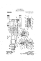
- F1gure 1 is a side elevation of a center crank straight-line com pressor embodying the invention, showing a portion of the steam chest in section, some of the parts being drawn on an exaggerated scale to show more plainly.
- Flg. 2 1s a plan view of a compressor embodying the invention.
- Fig. 3 is an enlarged partly sectional view of the steam cam and roll carriers.
- Fig. 4 is a section of the left end of the Steam controlling cam, cutting off at three quarters stroke.
- Figs. 5, 6 and 7 are sections of the same cam when the rollers are in osition respectivelyto cut oil at one halF stroke, one quarter stroke and at full cut-01f.
- Fig. 8 is a section of the left end of an air controlling cam.
- Figs. 9, 10 and '11 are sections of the same cam when the rollers are in position respectively to cut off at three quarters, one half, and one ,quarter stroke.
- Fig. 12 is an enlarged view of a speed governor partly in section.
- Fig. 13. is an enlarged sectional view showing the valves controlling the ports to the steam cylinder.
- Fig. 14 is a sectional view of the adjusting valve of the speed governor.
- Fig. 15 is a sectional View of an inlet valve.
- Fi 16 is a sectional view of a rotating stud and levers.
- -A is the steam cylinder
- B the air cylinder, which is provided with one or more discharge valves B oneach end, and with a discharge pipe B adapted to be connected with a receiver, not shown.
- the stems 13 ,13 of inlet-valves are shown at the left and right I on the bottom of the air cylinder, adapted to be mechanically opened by levers hereafter described, at the beginning of each suction stroke, and allowed to close at the end of the stroke, when working at full capacity, and allowed to close earlier in the stroke when working at less than full capacity, so that the air-intake is cut olf on the suction stroke, and a less volume is supplied to the receiver on the compression stroke.
- the inlet-valves remain closed when there is no demand for fluid. When closing early in the stroke, or remaining closed throughout the stroke, there is a partial vacuum in the cylinder, and the springs which tend to keep the inlet-valves seated must be strong enough to maintain them on their seats against the atmospheric pressure then tending to unseat them.
- Fig. 15 showsthe spring B adapted to seat and maintain the inlet-valve seated, except when mechanically opened.
- the air may pass to the valve through the port 13, communicating with an intake-pipe, and the stem B may pass through a cap, which is not shown, adapted to be screwed into the bottom of the cylinder. As shown withoutthe cap the air may. pass through the spider B of the valve. While only one inlet-valve is shown at each end, more maybe provided if necessary; but as the valves aremechanically pushed a considerable distance from their seats, the area of port opening is so large that one inlet-valve on eachend will generally be suflicient for cylinders of moderate capacity.
- the speed governor C is operated from some movable part of the apparatus; I have shown it driven from a pulley C fastened to the shaft D which revolves in unison with the engine shaft by means of I worm-gears E and F. Any suitable means may be employed to revolve shaft D in unison with the main shaft.
- the pulley C of the governor is belted to the pulley C and operates awsmall rotary pump.
- the pump may be of any suitable form of rotary" or plunger type.
- There is a chamber or reservoir in the casing containin oil or any suitable liquid which is pump through the port (3 (Fig. 12) under the piston and passes through port C to a recess of the semi-rotary valve C 'which laps over the port C", the latter port allowing the liquid to return to (lie chamber orreservoir.
- the adjusting screw Cis forced against-the which passes through and is adapted to'rotate the adjustin valve C.
- the valve C acts to partially close the rt C which is preferably longitudinal an at an angle to the upper seating face of the valve C (see- Fig. 14), so that a wide ran of the capacity'of port C may be obtaine
- port C is thus restricted, the liquid cannot return freely to the reservoir and it, therefore, creates a pressure under the piston C normally held down by. a weight describedlater herein, forcing it upward, and the stem G acts through levers and cams hereinafter described to shorten the point of cutoff to the steam c linder.
- the pressure regulator consists of a small air cylinder C connected by a pi e C to the receiver.
- the stem C is attached to a piston in the air cylinder C, and the link C is pivotally attached to the stem C" and the lever 0
- a weight C on the levertC'f is adjusted so that when the desired receiver pressure is attained, the pressure moves up the piston of the air cylinder C ca ing up the lever C-, thus movingthe a justing valve C to partially close the port C which acts to create a pres sure under the piston G and through the levers and cam to be described to shorten the point of cut-off and reduce the speed.
- the receiver pressure tends to increase and to still fur-- ther restrict the o ening of port C, and thus still further cut dawn the speed.
- the speed is thus reduced in proportion to the demand until the minimum s eed is reached, and the compressor is comp etely unloaded. If at this point there is a demand for air, the load can only be applied through a drop in the air pressure, which will act first to open the port C ,wider.
- cams there are two cams, one controlling the runs-between two rollers bearing on its pcriphery and placed diametrically opposite.
- the arrangement of rollers and carriages being similar for both cams, a description of one will be suflicient, except in relation to the difference in the shape of the cams which will be fully explained.
- the cams revolve with, and are by means of a key and keyway free toslide longitudinally on the shaft D, which I have shown driven in unison with the main shaft by the worm-gears E and F.
- the shaft is supported in bearings G G in the frame G which is bolted to the compressor.
- the right or steam controlling cam H is shown in its extreme position to the right. It is moved longitudinally-by means of the lever H having a forked end with slotted arms which engage the studs H of a split loose collar H located in a recess in the cam.
- the opposite end of the lever H is secured to a rocker shaft H supported by and rotatable in the frame G and the bearing C and carries on its opposite end the lever H provided with a weight H sufficient to move the cam H. to and maintain it in its righthand position when the force which moves it in an opposite direction is relieved.
- left or air controlling cam J is normallymoved to and maintained in its right-hand position by means of the weight J lever J rocker shaft J 2 supported by and rotatable in bearings J and in frame G, and lever arm J engaging studs of a split collar similar to H.
- the upper roller K is rotatably mounted in a roll carrier K which is provided with studs K adapted to slide vertically in bearings G? of the frame G.
- the lower roller K is rotatably mounted in a roll-carrier K provided with studs K adapted to slide vertically in bearings Gr of the frame G.
- the upper roll-carrier K carries a stud or shaft K adapted to move vertically in a boss or bearing K which is rigidly connected with the lower roll carrier K by an arm or yoke K (see' Fig. 1).
- A- spring K is placed between the bearing K and the roll-carrier K and by means of the adjusting nut K on the stud K the rollers K and K are allowed to engage the periphery of the cam at the desired tension, and answers to compensate for the wear of either the rollers or cam.
- the lower roll-carrier K is provided on the back side with a projecting stud indicated in Fig. 3, which engages the forked arm of a bell-crank lever L attached to a rocker-shaft L supported by a bearing L.
- a lever L is secured to the other end of shaft L pivotally attached to the connecting rod L the opposite end thereof being pivotally attached to the valve stem L which passes through stuffing boxes in each end of the steam chest A
- the heads or valves M and M are secured respectively on the left and right of the valve stem and control the left and right cylinder ports A and A.
- the cam J is operated between rollers in a roller-carriage similar to that provided for the cam H which has been described, and imparts a reciprocating movementvto a bellcrank lever O, and the connecting rod 0 pivotally connected thereto, and 'to the lever arm 0 secured to the rocker shaft 0, and supported by the bearing 0 which moves 'the levers O and O" alternately to open the inlet-valves of the air cylinder and to allow them to close.
- the construction of the steam controlling cam H is shown in Figs. 1, 3, 4, 5, 6 and 7.
- the pistons of both cylinders are in central position moving to the right, and revolving the main shaft in the direction denoted by the arrow in Fig. 1.
- the inlet-valve at the left of the air cylinder isopen and steam is being supplied to the left end of the steam cylinder through port A.
- Steam is being exhausted from the right end of the steam cylinder through port A and air is being compressed in the right end of the air cylinder,the inlet-valve at that end being closed.
- Both cams are revolving in the direction shown inFigs. 4 and 8, being sections of the left ends of the cams.
- the rollers are bearing on the left end of the cams and the steam valves M and M are in the positions 'marked respectively (Z andh in Fig. 13.
- the cam H is made with four separate concentric arc-shaped bearing surfaces, being parts of circles of difi'erent diameters.
- the curved surface joining the diflerent arcs acts to lift or push the rollers in opposite directions, a corresponding curve simultaneously acting to allow the respective opposite rollers to move in a corresponding direction at the proper time.
- the are of greatest radius or surface is designated 1, and the are or surface ofsmallest radius is designated 4, (see Fig. 7).
- the are or surface of second largest radius is designated 2
- gthe-remaining are or surface is designated 3.
- the roller K is forced 40 to surface 3, the lower roller K simultane ously moving to surface 2, causing the valve M to move to position e,thus cuttingfoif the admission of steam -to the left end of steam cylinder; while valve M is ,moved to position z', partially closing the exhaust from theright end of the c linder.
- the roller K is forced to surface 1; the roller K moves to surface 4, and valve M assumes tion 1; valveM" assumes position owi steam to pass to the right end 0 the cylin or, and to exhaust from the left end, and
- valve M assumes position g valve M -position k, and steam is out o from the right end of the cylinder, and the exhaust partially closed from the left end.
- roller K At the end of the left hand stroke, the roller K is forced to surface 1, and roller K moves to surface km the original position shown, completing the cycle of operation. It is not desirable to give any lead to the steam cam to admit steam before reaching The diametrical distances- .M and M assume ositions e and ,g and i cylinder (Pi down,
- the lifting surface may be slightly advanced in relation to its contact with the rollers at the end of the stroke.
- the cam could of course be constructed to furnish steam for the' entire stroke if the conditions demanded such. uneconomical action.
- the rollers bear on surfaces 2 and 3 alternately, and the valves and h opening and c osing the cylinder ports A and A to exhaust only.
- the weight on the lever arm C forces the piston of the air acting to increase the area of opemng of the port C and reducing the pressure under the piston C.
- the weight H on the lever arm H will, actin on the pivot piece C, force the piston down, and also move the cam H to the right, lengthening the point of cut-off and p acting either to increase the eed, or to compress a greater amount of aids-e111. stroke at the same speed or both, depen g upon.
- the relative longitudinal movement of the two cams is determined by the adj ustment of the levers H and J on the stud Hf and they are preferably adjusted so that the air cam will move faster than the steam cam H, gradually cutting off the air intake, but reaching the limit of its movement to completely unload the compressor before the steam cam has entirely out off the steam admission; but also gradually decreasing the speed untilthe point is reached where the steam furnished is just suflicient to keep the compressor in motion at friction load only.
- a straight line machine such as shown herein, it is of importance that it should hot stop or stick on centers.
- the compressor could be allowed to stop and would between a and a is when the air is expanded to atmospheric,
- the shape of the-air cam J is somewhat different but is similar in general principle to the cam H. It has three arc-shaped surfaces, the highest surface being designated as a (see Figs. 8 to 11), the intermediate 6, and the lowest 0. The diametrical distance equal to the diameter of the intermediate surface. In the position shown Figs. 1 and 8, the lower roller R isbearing on the surface a,
- a spring 0 hearing against the pivoted end 0 of the lever 0 allows the end 0 to move back when pressed against-the stem B at the beginning of the suction stroke, when the air in the clearance space is above atmospheric pressure, but at a point in the suction stroke pressure the spring 0 acts to open the inletvalve against the tension of the spring B which tends to keep the end of the stroke to the right, the surface a' forces the upper roller R to its .upper positionfthe lower roller R moving to surface 0, reversing the motion of the levers, pressing the lever 0" against the stem B* which causes the valve to open in the movement of the piston to the left when the end on the compression stroke has expanded to atmospheric 5 pressure the action of the spring 0 the valve seated.
- the left end inletvalve closed at the end of the stroke to the right when the lever O was moved down. At the end of ation described is reversed.
- the inlet-valve is opened as before, near the beginning of the suction stroke, but is allowed to close before the end of the stroke.
- the cam section shown is adapted to allow the inletvalve to close at three quarters stroke. During the stroke to the right, the rollers and valves are in the position before described.
- the surface I) forces the top roller R up, and the lower roller It moves from surface a to surface I) placing the bell-crank and other levers in an intermediate position by which the left hand inlet-valve is allowed to close, but the right hand is not opened.
- the surface a forces top roller R up, and lower roller R moves to the surface cas before described, remaining in this position during the stroke to the left until surface 6 forces the bottom roller R toan intermediate position at three quarter stroke.
- This allows the right hand inletvalve to close, and a volume less than the capacity of the cylinder is compressed at each stroke.
- the valves are closed still earlier in the stroke, as shown by Figs. 10 and 11, and this is continued until the surfaces a and 0 disappear from the periphery of the cam, and it is a true circle of surface 6, the inletvalves remaining closed throughout the stroke, and the compressor being completely unloaded.
- a'power cylinder and piston a compression cylinder and piston
- valves for controlling the admission of fluid to the cylinders means adapted throughout a wide range of speed to control the speed of the pistons, said means including fluid circulating means, a controllingvalve therefor and adjustable means to limit the movement of the controlling-valve, means for automatically varying the adjustment of said controlling-valve to change the speed of the pistons, so that the amount of fluid compressed will be substantially equal to the amount being used.
- valves for controlling the admission of' fluid to the cylinders means adapted throughout a 'wide range ofspeed to control the speed of the pistons, said means being also adapted to vary the amount of fluid compressed on the stroke of the compression piston, said meansincluding fluid circuthe stroke to the left, the oper- I 8O a v actuating said valves which are controlled der and piston,
- valves for controlling the admission of fluid to the cylinders mean adapted throughout a wide range of spee to control the s eed of the pistons, said means 'including uid circulating means, a controllingvalve therefor and adjustable means to limit the movement of the controlling-valve and means controlled by the pressure of the fluid compressed for varying the adjustment of said controlling-valve.
- a power cylinder and piston for controlling the admission of fluid 'to the cylinders, means adapted throughout a wide range of speed to control the s ed of the pistons, said means including uid circulatin means, a controllingvalve' and adjustao e means to limit the movement of the controlling-valve in opposite directions, and means controlled by the pressure of the fluid compressed for varying the adjustment of the controlling-valve to 'vary the speed at which said first mentioned means acts to increase. or decrease the speed of the pistons.
- a ower cylinder and piston a compression cylinder and piston
- valves for controlling the admission of fluid to the cylinders a governor provided with fluid circulating means, a controllingvalve and adjustable means to limit the movement of the controlling-valve and adapted throughout a wide range of speed to control the peed of the pistons, and means controlled by the pressure of the fluid compressed for varying the adjustment of the controlling-valve to vary the speed at which the governor acts to increase or de'-' crease the speed of the pistons.
- the combination'of a power cylinder and piston, a compression cylinder and piston, valves for controlling the admission of fluid to the cylinders, a governor adapted to control the speed of the pistons and being also adapted to vary theamount of fluidcompressed on the stroke of the compression piston, said governor being provided with means controlled by the presa piston, with means for supplying fluid to said governor piston and a controllingvalve and means controlled by the pressure of the fluid compressed by the compression piston for varying the adjustment of the controlling-valve.
- apparatus of the character de- In apparatus of the character de-, the combination of a power cylinder and piston, a compression cylinder and piston, valves for controlling the admission of fluid to the cylinders, a speed governor provided with a controlling-valve, means controlled by the pressure of the fluid compressed to operate the controlling-valve and adjustable means to limit the closing move ment of said controlling-valve to control the minimum speed of the pistons.
- a power cylinder and piston In apparatus of the character described, the combination of a power cylinder and piston, a compression cylinder and pistons, valves for controlling the admission of fluid to the cylinders, a speed governor provided with a controlling-valve, means controlled by the pressure of the fluid compressed to operate the controlling-valve and adjustable means to limit the opening movement of said controlling-valve to control the maximum 'speed of the pistons.
Landscapes
- Engineering & Computer Science (AREA)
- Mechanical Engineering (AREA)
- General Engineering & Computer Science (AREA)
- Control Of Positive-Displacement Pumps (AREA)
Description
G. L. BADGER. ENGINE DRIVEN COMPRESSOR;
APPLICATION FILED MAY 28, 1909.
Patented May 23, 1911.
' s sums-sum 1.
i ENN B w MW @VW \Q w w W 1 G.L.BADGBR.
BNGINE DRIVEN COMPRESSOR.
APPLICATION FILED MAY 29, 1909.
Patented May 23, 1911.
3 SHEETS-BEBE! B.
Wu! W4 ZZ Mfa v we yi.
kt u
@7 7 41AM 9W;
G. L. BADGER. ENGINE DRIVEN COMPRESSOR.
APPLICATION FILED MAY 29, 1909.
Patented May 23, 1911.
3 SHEETS-SHEET 3.
-GEORGE I1. BADGER, OF QUINCY, MASSACHUSETTS.
ENGINE-DRIVEN COMPRESSOR.
Specification of Letters Patent. .Paitented May 23, 1911.
Application filed May 29, 1909. Serial No. 499,178.
4 One of he principal objects of the inven-.
tion is to provide automatic re lating means which will control the spec of the compressor throughout a wide range, to vary the amount of fluid compressed, and also, after the speed has been reduced to a predetermined point, to varythe amount com ressed per stroke, without loss of power or e ciency.
A further object is to provide a more eflicient and economical by e of compressor,
especially as relates to t ose of comparatively small size, at but little increase in cost over the ordinary straight-line compressor. I
It is well known that the ordinary straight-line machine is not economically self regulating below to per cent. of its full rated capacity, and when the demand for fluid is light, the speed cannot be reduced sufliciently-to prevent waste of fluid without danger of the machine stalling or sticking on centers. By my inventlon a straight-line machine may, when there is but little demand for fluid, be operated nearly as slowly as a duplex machine, if desired, without loss of power or efliciency, exce t that due to an Increase in cylinder con ensation at very slow speeds as is the case in all types of steam engines.
A large number of the compressors installed-are of comparativel small size and are operated by plain sli e-valve engines having a fixed cut-oii' at a late point in the stroke and make no pretense to economical operation. Larger sizes are usually provided with an a justable cut-off which can be changed to cut oil the steam at difl'erenti points in the stroke, but on account of the variable demand for fluid, it is diflicult, if not impossible, for the attendant to anticipate what the demand will be at any time and to keep the cut-01f adjusted at the most economical oint. In practice the cut-ofl is usually ad' stroke in order to revent centering when the machine slows own, as the demand for fluid falls off, and there is a waste of steam when the machine speeds up again as the demand for fluid increases. Compressors of com aratively large capacity are usually of the uplex type provided. with cut-off valve gear, and havm compound steam cylinders, and with a lig t demand when these machines slow down in order to prevent a waste of the fluid compressed, they are liable to be stalled, unless special provisionis made to admit live steam at such times directly to the low pressure cylinder. Variable speed machines of the several classes herein mentioned are usually provided with a combined speed and pressure re ulator which regu latesthe amount of flui compressed by controlling the speed. The speed of the machine is normally controlled by the pressure of the fluid compressed, the regulator being provided with a piston which is subject to the fluid pressure, said piston furnishing directly the regulating t e admission of steam to the steam chest of the engine; or, in the case of an automatic cut-0fi' valve gear, furnishing directly the power for actuating the means for varying the oint in the stroke at which the valves 0 ose to cut oil the steam to the c linder. Such regulators are also provide with a fly-ball attachment, which ower to move the valve ,for
acts to reduce the supply of steam when waste of'fluid when the fluid compressed isat a predetermined pressure and the steam ressure is normal, if the steam, pressure alls oil while the pressure of the fluid compressed remains the same because of a decreased demand, the machine will stop on the centers since the speed will not be suflicient to give the required momentum.
In order to control the speed bf the maof the compressor is normally controlled by the pressure regulator which is cont-rolled by the pressure of the fluid compressed; but the pressure regulator does not act to vdirectly furnish power for actuating the means for changing the point of cut-off to vary the speed of the compressor; it simply acts to change the adjustment of the speed governor which varies the speed at which the governor acts to do the work. By this arrangement it will be seen that when the steam pressure is above a certain minimum amount, the speed of the compressor is not influenced or affected by variations of steam pressure, and that at either high or slow speeds the cut-off is automatically adjusted to the most economical point that is possible under the then existing conditions.
In order to avoid operating the compressor at full load per stroke at very slow speeds when little or no fluid is being used, I provide means whereby after the speed of the compressor has been reduced to a predetermined point,,the amount of fluid compressed per stroke is gradually decreased, so
that when the compressor is running at minimum speed, there will be no fluid compressed.
The invention will be fully understood from the following description taken in connection with the accompanying drawings, and the novel features are pointed out and clearly defined in the claims at the close of the specification.
In the drawings,F1gure 1 is a side elevation of a center crank straight-line com pressor embodying the invention, showing a portion of the steam chest in section, some of the parts being drawn on an exaggerated scale to show more plainly. Flg. 2 1s a plan view of a compressor embodying the invention. Fig. 3 is an enlarged partly sectional view of the steam cam and roll carriers. Fig. 4 is a section of the left end of the Steam controlling cam, cutting off at three quarters stroke. Figs. 5, 6 and 7 are sections of the same cam when the rollers are in osition respectivelyto cut oil at one halF stroke, one quarter stroke and at full cut-01f. Fig. 8 is a section of the left end of an air controlling cam. Figs. 9, 10 and '11 are sections of the same cam when the rollers are in position respectively to cut off at three quarters, one half, and one ,quarter stroke. Fig. 12 is an enlarged view of a speed governor partly in section. Fig. 13. is an enlarged sectional view showing the valves controlling the ports to the steam cylinder. Fig. 14 is a sectional view of the adjusting valve of the speed governor. Fig. 15 is a sectional View of an inlet valve. Fi 16 is a sectional view of a rotating stud and levers.
Referring to the drawings, -A is the steam cylinder, and B the air cylinder, which is provided with one or more discharge valves B oneach end, and with a discharge pipe B adapted to be connected with a receiver, not shown. The stems 13 ,13 of inlet-valves are shown at the left and right I on the bottom of the air cylinder, adapted to be mechanically opened by levers hereafter described, at the beginning of each suction stroke, and allowed to close at the end of the stroke, when working at full capacity, and allowed to close earlier in the stroke when working at less than full capacity, so that the air-intake is cut olf on the suction stroke, and a less volume is supplied to the receiver on the compression stroke. The inlet-valves remain closed when there is no demand for fluid. When closing early in the stroke, or remaining closed throughout the stroke, there is a partial vacuum in the cylinder, and the springs which tend to keep the inlet-valves seated must be strong enough to maintain them on their seats against the atmospheric pressure then tending to unseat them.
Fig. 15 showsthe spring B adapted to seat and maintain the inlet-valve seated, except when mechanically opened. The air may pass to the valve through the port 13, communicating with an intake-pipe, and the stem B may pass through a cap, which is not shown, adapted to be screwed into the bottom of the cylinder. As shown withoutthe cap the air may. pass through the spider B of the valve. While only one inlet-valve is shown at each end, more maybe provided if necessary; but as the valves aremechanically pushed a considerable distance from their seats, the area of port opening is so large that one inlet-valve on eachend will generally be suflicient for cylinders of moderate capacity.
While the compressor could be regulated by the air cylinder alone to control the amount of fluid compressed, I have provided means to reduce thespeed of the compressor before cutting off the amount compressed per stroke. The speed governor C is operated from some movable part of the apparatus; I have shown it driven from a pulley C fastened to the shaft D which revolves in unison with the engine shaft by means of I worm-gears E and F. Any suitable means may be employed to revolve shaft D in unison with the main shaft. The pulley C of the governor is belted to the pulley C and operates awsmall rotary pump. The
casing which forms part of the governor 1s represented'by '0. The pump may be of any suitable form of rotary" or plunger type. There is a chamber or reservoir in the casing containin oil or any suitable liquid which is pump through the port (3 (Fig. 12) under the piston and passes through port C to a recess of the semi-rotary valve C 'which laps over the port C", the latter port allowing the liquid to return to (lie chamber orreservoir. The port C, as well as ports the compressor at the desired speed, and
' lever C" attached to a shaft or stem C",
the adjusting screw Cis forced against-the which passes through and is adapted to'rotate the adjustin valve C. When the lever C is thus force upward, the valve C (see Fig. 12) acts to partially close the rt C which is preferably longitudinal an at an angle to the upper seating face of the valve C (see- Fig. 14), so that a wide ran of the capacity'of port C may be obtaine When port C is thus restricted, the liquid cannot return freely to the reservoir and it, therefore, creates a pressure under the piston C normally held down by. a weight describedlater herein, forcing it upward, and the stem G acts through levers and cams hereinafter described to shorten the point of cutoff to the steam c linder. When the steam is thus cutoff su ciently tib slightly reduce .the speed,.'the check-nut of the adjusting screwris tightened, and the throttle opene and the governor has the maximum speed of the apparatus under control, and will, if desired, maintain the speed if the steam pressure is high enough to work against the load. When the speed decreases s ghtly, a lessamountof liquid is pumped, and as a less amount will pass more port C, the prasure under thepiston 0 decreases and the weight before mentioned carriesfit down toward its original position,
moving the cam to lengthen the point of cutofi, thus increasing t e speed. An orifice a through the adjusting valve, not shown, permits-t-he pressure of the liquid being pum to hold it to its seat. Having thus provi ed for controlling the maximum speed, the governor'is adjusted to control the minimum ver 0 in contact with the adjusting screw -to increase the speed, simu freely through.
speed, by' bringing the left end C of the le-' will maintain the compressor in motion under a friction load only. This revents further closing of the port. C. he cam will automatically move to a point to maintain this minimum speed whenever the compressor is completely unloaded irrespective of the steam pressure. Provision has been made so that when the load comes on, it is applied gradually and the steam supplied increases proportionately. This is accomplished'by means of a pressure regulator which actuates the adjusting semi-rotary valve 0 of the speed governor, and thus controls the position of the actuating cams,-
and times the movements of the steam and air-valves. v
The pressure regulator consists of a small air cylinder C connected by a pi e C to the receiver. The stem C is attached to a piston in the air cylinder C, and the link C is pivotally attached to the stem C" and the lever 0 A weight C on the levertC'f is adjusted so that when the desired receiver pressure is attained, the pressure moves up the piston of the air cylinder C ca ing up the lever C-, thus movingthe a justing valve C to partially close the port C which acts to create a pres sure under the piston G and through the levers and cam to be described to shorten the point of cut-off and reduce the speed. As
the demand for fluid decreases, the receiver pressure tends to increase and to still fur-- ther restrict the o ening of port C, and thus still further cut dawn the speed. The speed is thus reduced in proportion to the demand until the minimum s eed is reached, and the compressor is comp etely unloaded. If at this point there is a demand for air, the load can only be applied through a drop in the air pressure, which will act first to open the port C ,wider. This will allow the Oll or liquid being pumped to return more freely to the reservolr of the speed governor as before-explained, and permit the cum to be moved to a position to supply more steam taneously permitting the air cylinder to compress a small amount of air which will increase in proportion to the demand for fluid. But additional steam will simultaneously be furilisged'at a similar ratio to take care of the ca Y The actuating and timing of the movements of the steam and air valves during the stroke of the pistons in either directionris accomplished by means of cams running be.- tween rollers attached to carriages, the rotation of the cams imparting a reciprocating movement to the roller-carriages, which motion is imparted by levers to the valves. There are two cams, one controlling the runs-between two rollers bearing on its pcriphery and placed diametrically opposite. The arrangement of rollers and carriages being similar for both cams, a description of one will be suflicient, except in relation to the difference in the shape of the cams which will be fully explained.
, The cams revolve with, and are by means of a key and keyway free toslide longitudinally on the shaft D, which I have shown driven in unison with the main shaft by the worm-gears E and F. The shaft is supported in bearings G G in the frame G which is bolted to the compressor.
The right or steam controlling cam H is shown in its extreme position to the right. It is moved longitudinally-by means of the lever H having a forked end with slotted arms which engage the studs H of a split loose collar H located in a recess in the cam. The opposite end of the lever H is secured to a rocker shaft H supported by and rotatable in the frame G and the bearing C and carries on its opposite end the lever H provided with a weight H sufficient to move the cam H. to and maintain it in its righthand position when the force which moves it in an opposite direction is relieved. The
left or air controlling cam J is normallymoved to and maintained in its right-hand position by means of the weight J lever J rocker shaft J 2 supported by and rotatable in bearings J and in frame G, and lever arm J engaging studs of a split collar similar to H. The upper roller K is rotatably mounted in a roll carrier K which is provided with studs K adapted to slide vertically in bearings G? of the frame G. The lower roller K is rotatably mounted in a roll-carrier K provided with studs K adapted to slide vertically in bearings Gr of the frame G.
The upper roll-carrier K carries a stud or shaft K adapted to move vertically in a boss or bearing K which is rigidly connected with the lower roll carrier K by an arm or yoke K (see' Fig. 1). A- spring K is placed between the bearing K and the roll-carrier K and by means of the adjusting nut K on the stud K the rollers K and K are allowed to engage the periphery of the cam at the desired tension, and answers to compensate for the wear of either the rollers or cam. \Vhen the cam moves the rollers,.the spring is stiff enough not to be compressed and will transmit the motion and actuate the valves but will yield slightly if the distance between the bearing line of the oppositely disposed rollers on the cam is not correctly proportioned throughout the revolution of the cam. By this arrangement of rollers and cam I obtain the necessary reciprocating movement with but little friction between the cam and rollers, one
roller being pushed in one direction and the other in an opposite direction, the cam being so shaped that when one roller -is moving to a high portion, the opposite one is moving to a low portion of the cam. V
The lower roll-carrier K is provided on the back side with a projecting stud indicated in Fig. 3, which engages the forked arm of a bell-crank lever L attached to a rocker-shaft L supported by a bearing L. A lever L is secured to the other end of shaft L pivotally attached to the connecting rod L the opposite end thereof being pivotally attached to the valve stem L which passes through stuffing boxes in each end of the steam chest A The heads or valves M and M are secured respectively on the left and right of the valve stem and control the left and right cylinder ports A and A.
Steam is admitted to the chest through the pipe connection A, and passes by ports A and A to the outer ends of the steam chest, thus balancing the pressure 011 the valves and permitting a free longitudinal movement. The exhaust port A is located between the valves. A single or integral valve with an exhaust space between the heads could be used, or a plain or balanced slide valve, but it is desirable to employ a valve which will move easily in both directions.
The cam J is operated between rollers in a roller-carriage similar to that provided for the cam H which has been described, and imparts a reciprocating movementvto a bellcrank lever O, and the connecting rod 0 pivotally connected thereto, and 'to the lever arm 0 secured to the rocker shaft 0, and supported by the bearing 0 which moves 'the levers O and O" alternately to open the inlet-valves of the air cylinder and to allow them to close. v i
The construction of the steam controlling cam H is shown in Figs. 1, 3, 4, 5, 6 and 7. In the position shown inFigs. 1, 3 and 4 the pistons of both cylinders are in central position moving to the right, and revolving the main shaft in the direction denoted by the arrow in Fig. 1. The inlet-valve at the left of the air cylinderisopen and steam is being supplied to the left end of the steam cylinder through port A. Steam is being exhausted from the right end of the steam cylinder through port A and air is being compressed in the right end of the air cylinder,the inlet-valve at that end being closed. Both cams are revolving in the direction shown inFigs. 4 and 8, being sections of the left ends of the cams. The rollers are bearing on the left end of the cams and the steam valves M and M are in the positions 'marked respectively (Z andh in Fig. 13.
The cam H is made with four separate concentric arc-shaped bearing surfaces, being parts of circles of difi'erent diameters. The curved surface joining the diflerent arcs acts to lift or push the rollers in opposite directions, a corresponding curve simultaneously acting to allow the respective opposite rollers to move in a corresponding direction at the proper time. The are of greatest radius or surface is designated 1, and the are or surface ofsmallest radius is designated 4, (see Fig. 7). When one roller is bearing on surface 1, the opposite roller heal-son surface 4, and vice versa. The are or surface of second largest radius is designated 2, and gthe-remaining are or surface is designated 3. When one roller is hearing on surface 2, the opposite roller is hearing on surface 3, and vice versa. between surfaces 1 and 4 and between 2 and .5 3 are equal, but where the surfaces are joined by the lifting line of the cam, the diametri cal line is not the same as between the arcs, since in moving from one are or surface to another the rollers do not bear in a straight line drawn through their centers but at a point off the center line determined by the relative diameters of the cam and roller, and the length of the surface-joining the arcs, representing the time which it takes the cam to move the roller from one to the other position when revolving.
In the position shown in Figs. 1, 3 and 4, the bottom roller K vis bearing on the high surface 1 of the cam. H and is in its extreme downward position carrying the valve stem to its extreme position to the right and placing the valve M in position (1, opening the port A to admit steam to the left end of the steam cylinder; while the upper roller K is bearing on the low surface 4, valve M is in position It to exhaust steam from the right end of the cylinder, 'throughport A". As the piston moving to the right reaches three quarter stroke, the roller K is forced 40 to surface 3, the lower roller K simultane ously moving to surface 2, causing the valve M to move to position e,thus cuttingfoif the admission of steam -to the left end of steam cylinder; while valve M is ,moved to position z', partially closing the exhaust from theright end of the c linder. At the end of the stroke to the right, the roller K is forced to surface 1; the roller K moves to surface 4, and valve M assumes tion 1; valveM" assumes position owi steam to pass to the right end 0 the cylin or, and to exhaust from the left end, and
moving the piston to the left. Whenreachthree-quarter stroke to the left, the lower r0 or K is forced to surface K moves to surface 4; valve M assumes position g valve M -position k, and steam is out o from the right end of the cylinder, and the exhaust partially closed from the left end.
At the end of the left hand stroke, the roller K is forced to surface 1, and roller K moves to surface km the original position shown, completing the cycle of operation. It is not desirable to give any lead to the steam cam to admit steam before reaching The diametrical distances- .M and M assume ositions e and ,g and i cylinder (Pi down,
the end of the stroke, since ordinarily the air cylinder acts to cushion the piston.
If the conditions were-such that it was desirable to provide a cushion, the lifting surface may be slightly advanced in relation to its contact with the rollers at the end of the stroke. The cam could of course be constructed to furnish steam for the' entire stroke if the conditions demanded such. uneconomical action. "[5
Whenever at three quarters cut-off the compressor speed or the air pressure increases the speed governor and ressure re ulator come into action, and t e piston being forced up, the stem C forces up one end of the pivot piece 0 sup orted in hearing C and the o posite end orces the short arm of lever H own, and acts through the rocker shaft H to move the lower end of lever H to the left, thus moving the cam, which then acts gradually as it moves longitudinally to shorten the point of cut-off. When the cam cuts oil at one half stroke, a section at that point would'appear like Fig. 5, and at quarter stroke like Fig. 6. The point of cut-off is gradually shortened until finally the surfaces 1 and 4 disappear from the periphery of the cam. As before stated, a slight advance may be made in the lift line to provide a cushioning effect if desired. When the cam has moved longitudinally to bring that portion of the cam shown in Fig.
7 between the rollers, the rollers bear on surfaces 2 and 3 alternately, and the valves and h opening and c osing the cylinder ports A and A to exhaust only. When the demand for fluid increases, and the receiver pressureef slightly, the weight on the lever arm C" forces the piston of the air acting to increase the area of opemng of the port C and reducing the pressure under the piston C. The weight H on the lever arm H will, actin on the pivot piece C, force the piston down, and also move the cam H to the right, lengthening the point of cut-off and p acting either to increase the eed, or to compress a greater amount of aids-e111. stroke at the same speed or both, depen g upon. the relative a jnstmento'f the steam and air His desirable in some cases to compress a full amount per stroke under li ht. loads, running the compressor at a sp in compress'an amount suflicient to equal the dem'and. Just before the speed is reduced to a point where a too early 'cut-ofi would prevent smooth running, the lever H is adjusted to abut against the lever H which is mo m the 1 's. The 16m 11' is sc cared to a stud H suppprted by and rotat- 4 ingin the frame G (see ig. 16), carnes the, slotted lever arm J the slot fitting over a flattened place on the stud, Ion- I gitudinal adjustment of the lever J 9 on the stud H and retained in adjusted position by the nuts H so that the stud and levers swing freely. Any further movement of the lever H will through the action of theswinging arms H and J move the cam J to the left, and act to cut off the amount of air drawn in on each suction stroke of the air piston. The relative longitudinal movement of the two cams is determined by the adj ustment of the levers H and J on the stud Hf and they are preferably adjusted so that the air cam will move faster than the steam cam H, gradually cutting off the air intake, but reaching the limit of its movement to completely unload the compressor before the steam cam has entirely out off the steam admission; but also gradually decreasing the speed untilthe point is reached where the steam furnished is just suflicient to keep the compressor in motion at friction load only. In a straight line machine, such as shown herein, it is of importance that it should hot stop or stick on centers. In a duplex machine with cranks set at 90 degrees the compressor could be allowed to stop and would between a and a is when the air is expanded to atmospheric,
air entrapped in the right start in any position.
The shape of the-air cam J is somewhat different but is similar in general principle to the cam H. It has three arc-shaped surfaces, the highest surface being designated as a (see Figs. 8 to 11), the intermediate 6, and the lowest 0. The diametrical distance equal to the diameter of the intermediate surface. In the position shown Figs. 1 and 8, the lower roller R isbearing on the surface a,
and the upper roller R is hearing on the surface 0. A stud engages the forked end of the bell-crank lever 0 forcing it down, and the upper end to the right; The connecting rod 0 and lever 0 are also forced to the right, and the rocker arm 0 causes the left end of lever O to bear against the stem B *ofthe left inlet valve and open the same. A spring 0 hearing against the pivoted end 0 of the lever 0 allows the end 0 to move back when pressed against-the stem B at the beginning of the suction stroke, when the air in the clearance space is above atmospheric pressure, but at a point in the suction stroke pressure the spring 0 acts to open the inletvalve against the tension of the spring B which tends to keep the end of the stroke to the right, the surface a' forces the upper roller R to its .upper positionfthe lower roller R moving to surface 0, reversing the motion of the levers, pressing the lever 0" against the stem B* which causes the valve to open in the movement of the piston to the left when the end on the compression stroke has expanded to atmospheric 5 pressure the action of the spring 0 the valve seated. At
similar to 0 described; the left end inletvalve closed at the end of the stroke to the right when the lever O was moved down. At the end of ation described is reversed. When it is desired to cut off a portion of the air on the suction stroke, the inlet-valve is opened as before, near the beginning of the suction stroke, but is allowed to close before the end of the stroke. Referring to Fig. 9, the cam section shown is adapted to allow the inletvalve to close at three quarters stroke. During the stroke to the right, the rollers and valves are in the position before described. At three quarters stroke the surface I) forces the top roller R up, and the lower roller It moves from surface a to surface I) placing the bell-crank and other levers in an intermediate position by which the left hand inlet-valve is allowed to close, but the right hand is not opened. At the end of the stroke to the right the surface a forces top roller R up, and lower roller R moves to the surface cas before described, remaining in this position during the stroke to the left until surface 6 forces the bottom roller R toan intermediate position at three quarter stroke. This allows the right hand inletvalve to close, and a volume less than the capacity of the cylinder is compressed at each stroke. As the cam moves to the left, the valves are closed still earlier in the stroke, as shown by Figs. 10 and 11, and this is continued until the surfaces a and 0 disappear from the periphery of the cam, and it is a true circle of surface 6, the inletvalves remaining closed throughout the stroke, and the compressor being completely unloaded.
What I claim is: v
1. In apparatus of the character described. the combination of a'power cylinder and piston, a compression cylinder and piston, valves for controlling the admission of fluid to the cylinders, means adapted throughout a wide range of speed to control the speed of the pistons, said means including fluid circulating means, a controllingvalve therefor and adjustable means to limit the movement of the controlling-valve, means for automatically varying the adjustment of said controlling-valve to change the speed of the pistons, so that the amount of fluid compressed will be substantially equal to the amount being used.
2. In apparatus of the character described, the combination of a power cylinder and piston, a compression cylinder and piston, valves for controlling the admission of' fluid to the cylinders, means adapted throughout a 'wide range ofspeed to control the speed of the pistons, said means being also adapted to vary the amount of fluid compressed on the stroke of the compression piston, said meansincluding fluid circuthe stroke to the left, the oper- I 8O a v actuating said valves which are controlled der and piston,
lating means, a controlling-valve therefor and adjustable means to limit the movement of the controlling-valve, means for automatically'varying the-adjustment of said controlling-valve to change the speed of the pistons.
3. In apparatus. of the character described, the combination of a power cylina compression cylinder and piston, valves for controlling the admission of fluid to the cylinders, a governor provided with fluid circulating means, a con- "trolling-valve therefor and adjustable means speed of the pistons,
' fluid to the cylinders, a speed governor pro:
' valve to vided with fluid circulating means, a controlling-valve therefor and adjustable means to limit the movement of the controlling valve and mechanically operated means for by said governor, means for automatically varying theadjustment of said controlling- I change the speed of the pistons, so that the amount of fluid compressed ,will
be substantially equal to the amount being used.
5. In apparatus of the character described, the combination of a power cylinder and piston, a compression cylinder and piston, valves for controlling the admission of fluid to the cylinders, mean adapted throughout a wide range of spee to control the s eed of the pistons, said means 'including uid circulating means, a controllingvalve therefor and adjustable means to limit the movement of the controlling-valve and means controlled by the pressure of the fluid compressed for varying the adjustment of said controlling-valve.
6. In. apparatus of the character described, the combination of a power cylinder and piston, a compression cylinder and piston, valves for controlling the admission of fluid to the cylinders, means adapted throughout a wide range of speed to control the s eed of the pistons, said means includin uid circulating means, a controllingva ve therefor and adjustable means to limit the movement of the controlling-valve, said means being also adapted to vary the amount of fluid compressed on the stroke of the compression piston.
7. In apparatus of the character described, the combination of a power cylinder and piston, a compressioncylinder and piston, valves for controlling the admission of fluid -to the cylinders, means adapted thro'ughout'a wide range of speed to control the speed of the'pistons, said means being also adapted to vary the amount of fluid compressed on the stroke of the compression piston, said means includin a controllingvalve,and means controlled %)y the pressure of the fluid compressed for varying the adustment of the controlling-valve to vary the sp eed at which said first mentioned means acts to increase or decrease the speed of the pistons.
8. In apparatus of the character described, the combination of a power cylinder and piston, a compression cylinder and piston, valves for controlling the admission of fluid 'to the cylinders, means adapted throughout a wide range of speed to control the s ed of the pistons, said means including uid circulatin means, a controllingvalve' and adjustao e means to limit the movement of the controlling-valve in opposite directions, and means controlled by the pressure of the fluid compressed for varying the adjustment of the controlling-valve to 'vary the speed at which said first mentioned means acts to increase. or decrease the speed of the pistons.
9. In apparatus of the character described, the combination of a ower cylinder and piston, a compression cylinder and piston, valves for controlling the admission of fluid to the cylinders, a governor provided with fluid circulating means, a controllingvalve and adjustable means to limit the movement of the controlling-valve and adapted throughout a wide range of speed to control the peed of the pistons, and means controlled by the pressure of the fluid compressed for varying the adjustment of the controlling-valve to vary the speed at which the governor acts to increase or de'-' crease the speed of the pistons.
10. In apparatus of, the character described, the combination of a power cylinder and piston, a compression cy nder and piston, valves for controlling the admission of fluid to the cylinders, a governor provided with a piston, with means for supplying fluid to said overnor piston and a controlling-valve and sure of the fluid compressed by the compression piston for varying the adjustment of said controlling-valve.
11. In apparatus of the character described, the combination'of a power cylinder and piston, a compression cylinder and piston, valves for controlling the admission of fluid to the cylinders, a governor adapted to control the speed of the pistons and being also adapted to vary theamount of fluidcompressed on the stroke of the compression piston, said governor being provided with means controlled by the presa piston, with means for supplying fluid to said governor piston and a controllingvalve and means controlled by the pressure of the fluid compressed by the compression piston for varying the adjustment of the controlling-valve.
12. In apparatus of the character described, the combination of a power cylinder and piston, a compression cylinder and piston, valves for controlling the admission of fluid to the cylinders, avariable speed governor provided with a controlling-valve, a lever adapted to move the controlling-valve and means controlled by the pressure of the fluid compressed to operate said lever.
13. scribed, the combination of a power cylinder and piston, a compression cylinder and piston, valves for controlling the admission of fluid to the cylinders, a speed governor provided with a controlling-valve, a lever adapted to move the controlling-valve, means. controlled 'by the pressure of the fluid compressed to operate the lever and adjustable means to limit the movement of said lever.
14. In apparatus of the character de- In apparatus of the character de-' scribed, the combination of a power cylinder and piston, a compression cylinder and piston, valves for controlling the admission of fluid to the cylinders, a speed governor provided with a controlling-valve, means controlled by the pressure of the fluid compressed to operate the controlling-valve and adjustable means to limit the closing move ment of said controlling-valve to control the minimum speed of the pistons.
/ 15. In apparatus of the character described, the combination of a power cylinder and piston, a compression cylinder and pistons, valves for controlling the admission of fluid to the cylinders, a speed governor provided with a controlling-valve, means controlled by the pressure of the fluid compressed to operate the controlling-valve and adjustable means to limit the opening movement of said controlling-valve to control the maximum 'speed of the pistons.
In testimony whereof I afiix my signature, in presence of two witnesses.
GEORGE L. BADGER. Witnesses:
WILLIAM A. COPELAND, ALICE H. MORRISON.
Priority Applications (1)
| Application Number | Priority Date | Filing Date | Title |
|---|---|---|---|
| US49917809A US992932A (en) | 1909-05-29 | 1909-05-29 | Engine-driven compressor. |
Applications Claiming Priority (1)
| Application Number | Priority Date | Filing Date | Title |
|---|---|---|---|
| US49917809A US992932A (en) | 1909-05-29 | 1909-05-29 | Engine-driven compressor. |
Publications (1)
| Publication Number | Publication Date |
|---|---|
| US992932A true US992932A (en) | 1911-05-23 |
Family
ID=3061266
Family Applications (1)
| Application Number | Title | Priority Date | Filing Date |
|---|---|---|---|
| US49917809A Expired - Lifetime US992932A (en) | 1909-05-29 | 1909-05-29 | Engine-driven compressor. |
Country Status (1)
| Country | Link |
|---|---|
| US (1) | US992932A (en) |
-
1909
- 1909-05-29 US US49917809A patent/US992932A/en not_active Expired - Lifetime
Similar Documents
| Publication | Publication Date | Title |
|---|---|---|
| US2129828A (en) | Pump | |
| US2200892A (en) | Regulating device for compressed fluid generators of the free pistons type | |
| US2266077A (en) | Internal combustion engine | |
| US2714858A (en) | Rotary compressors or pumps, in combination with hydraulic controls, and mechanical controls in co-ordination therewith | |
| US2201682A (en) | Plant comprising two or more pressure medium generators | |
| US2942774A (en) | Compressor and controlling means therefor | |
| US2305310A (en) | Internal combustion engine | |
| US872598A (en) | Gas-engine. | |
| US2123009A (en) | Internal combustion power plant | |
| US1335065A (en) | Revolving-cylinder engine | |
| US1789785A (en) | Hydraulic speed change | |
| US993653A (en) | Hydraulic power-transmission system. | |
| US1394802A (en) | Unloading apparatus for compressors | |
| US1138215A (en) | Air-compressor. | |
| US2464636A (en) | Fluid pressure control system | |
| US1998265A (en) | Compressor control mechanism | |
| US2211875A (en) | Compressor control system | |
| US2277135A (en) | Compressor apparatus | |
| US2454363A (en) | Compressor control mechanism | |
| US2612753A (en) | Constant speed pump and motor hydraulic transmission | |
| US1582763A (en) | Internal-combustion engine | |
| US635690A (en) | Engine. | |
| US647669A (en) | Steam-engine. | |
| US605805A (en) | Rotary steam-engine | |
| US418548A (en) | Petebs |