US9925480B2 - End cap retention device - Google Patents

End cap retention device Download PDF

Info

Publication number
US9925480B2
US9925480B2 US14/375,920 US201214375920A US9925480B2 US 9925480 B2 US9925480 B2 US 9925480B2 US 201214375920 A US201214375920 A US 201214375920A US 9925480 B2 US9925480 B2 US 9925480B2
Authority
US
United States
Prior art keywords
retainer
end cap
wall
bonding agent
cavity
Prior art date
Legal status (The legal status is an assumption and is not a legal conclusion. Google has not performed a legal analysis and makes no representation as to the accuracy of the status listed.)
Active, expires
Application number
US14/375,920
Other versions
US20150021256A1 (en
Inventor
Kenneth M. Luther
Michael R. Sexsmith
Current Assignee (The listed assignees may be inaccurate. Google has not performed a legal analysis and makes no representation or warranty as to the accuracy of the list.)
Parker Intangibles LLC
Original Assignee
Parker Hannifin Corp
Priority date (The priority date is an assumption and is not a legal conclusion. Google has not performed a legal analysis and makes no representation as to the accuracy of the date listed.)
Filing date
Publication date
Application filed by Parker Hannifin Corp filed Critical Parker Hannifin Corp
Priority to US14/375,920 priority Critical patent/US9925480B2/en
Assigned to PARKER-HANNIFIN CORPORATION reassignment PARKER-HANNIFIN CORPORATION ASSIGNMENT OF ASSIGNORS INTEREST (SEE DOCUMENT FOR DETAILS). Assignors: LUTHER, KENNETH M., SEXSMITH, MICHAEL R.
Publication of US20150021256A1 publication Critical patent/US20150021256A1/en
Application granted granted Critical
Publication of US9925480B2 publication Critical patent/US9925480B2/en
Assigned to PARKER INTANGIBLES, LLC reassignment PARKER INTANGIBLES, LLC ASSIGNMENT OF ASSIGNORS INTEREST (SEE DOCUMENT FOR DETAILS). Assignors: PARKER-HANNIFIN CORPORATION
Active legal-status Critical Current
Adjusted expiration legal-status Critical

Links

Images

Classifications

    • BPERFORMING OPERATIONS; TRANSPORTING
    • B01PHYSICAL OR CHEMICAL PROCESSES OR APPARATUS IN GENERAL
    • B01DSEPARATION
    • B01D29/00Filters with filtering elements stationary during filtration, e.g. pressure or suction filters, not covered by groups B01D24/00 - B01D27/00; Filtering elements therefor
    • B01D29/11Filters with filtering elements stationary during filtration, e.g. pressure or suction filters, not covered by groups B01D24/00 - B01D27/00; Filtering elements therefor with bag, cage, hose, tube, sleeve or like filtering elements
    • B01D29/13Supported filter elements
    • BPERFORMING OPERATIONS; TRANSPORTING
    • B01PHYSICAL OR CHEMICAL PROCESSES OR APPARATUS IN GENERAL
    • B01DSEPARATION
    • B01D29/00Filters with filtering elements stationary during filtration, e.g. pressure or suction filters, not covered by groups B01D24/00 - B01D27/00; Filtering elements therefor
    • B01D29/0093Making filtering elements not provided for elsewhere
    • BPERFORMING OPERATIONS; TRANSPORTING
    • B01PHYSICAL OR CHEMICAL PROCESSES OR APPARATUS IN GENERAL
    • B01DSEPARATION
    • B01D29/00Filters with filtering elements stationary during filtration, e.g. pressure or suction filters, not covered by groups B01D24/00 - B01D27/00; Filtering elements therefor
    • B01D29/11Filters with filtering elements stationary during filtration, e.g. pressure or suction filters, not covered by groups B01D24/00 - B01D27/00; Filtering elements therefor with bag, cage, hose, tube, sleeve or like filtering elements
    • B01D29/13Supported filter elements
    • B01D29/15Supported filter elements arranged for inward flow filtration
    • B01D29/21Supported filter elements arranged for inward flow filtration with corrugated, folded or wound sheets
    • BPERFORMING OPERATIONS; TRANSPORTING
    • B01PHYSICAL OR CHEMICAL PROCESSES OR APPARATUS IN GENERAL
    • B01DSEPARATION
    • B01D46/00Filters or filtering processes specially modified for separating dispersed particles from gases or vapours
    • B01D46/24Particle separators, e.g. dust precipitators, using rigid hollow filter bodies
    • B01D46/2403Particle separators, e.g. dust precipitators, using rigid hollow filter bodies characterised by the physical shape or structure of the filtering element
    • B01D46/2411Filter cartridges
    • B01D46/2414End caps including additional functions or special forms
    • BPERFORMING OPERATIONS; TRANSPORTING
    • B01PHYSICAL OR CHEMICAL PROCESSES OR APPARATUS IN GENERAL
    • B01DSEPARATION
    • B01D2201/00Details relating to filtering apparatus
    • B01D2201/12Pleated filters
    • B01D2201/127Pleated filters with means for keeping the spacing between the pleats
    • BPERFORMING OPERATIONS; TRANSPORTING
    • B01PHYSICAL OR CHEMICAL PROCESSES OR APPARATUS IN GENERAL
    • B01DSEPARATION
    • B01D2201/00Details relating to filtering apparatus
    • B01D2201/29Filter cartridge constructions
    • B01D2201/291End caps
    • BPERFORMING OPERATIONS; TRANSPORTING
    • B01PHYSICAL OR CHEMICAL PROCESSES OR APPARATUS IN GENERAL
    • B01DSEPARATION
    • B01D2265/00Casings, housings or mounting for filters specially adapted for separating dispersed particles from gases or vapours
    • B01D2265/04Permanent measures for connecting different parts of the filter, e.g. welding, glueing or moulding
    • YGENERAL TAGGING OF NEW TECHNOLOGICAL DEVELOPMENTS; GENERAL TAGGING OF CROSS-SECTIONAL TECHNOLOGIES SPANNING OVER SEVERAL SECTIONS OF THE IPC; TECHNICAL SUBJECTS COVERED BY FORMER USPC CROSS-REFERENCE ART COLLECTIONS [XRACs] AND DIGESTS
    • Y10TECHNICAL SUBJECTS COVERED BY FORMER USPC
    • Y10TTECHNICAL SUBJECTS COVERED BY FORMER US CLASSIFICATION
    • Y10T29/00Metal working
    • Y10T29/49Method of mechanical manufacture
    • Y10T29/49826Assembling or joining

Definitions

  • the present invention relates generally to filter assemblies, and more particularly to end caps for filter assemblies.
  • Filter assemblies have been employed in a variety of applications including hydraulic systems, fuel systems and engine lubrication systems.
  • High pressure hydraulic systems for example, require long component life and high performance standards.
  • hydraulic components are built with tight tolerances, which increase sensitivity to contamination.
  • Filter assemblies can be used to filter out ingressed contamination before the contamination jams a valve or scores a cylinder, to block pump generated debris before it reaches servo and proportional valves in the hydraulic systems, etc.
  • the filter assemblies can include a filtration media such as a wire reinforced pleated filtration media.
  • the wire reinforcement prevents the pleats from bunching, prevents media migration, and maintains media efficiency. By preventing the pleats from bunching, for example, the wire reinforcement prevent the effective surface area of the filter from being reduced and prevents excessive pressure drop.
  • the present invention provides a filter assembly including at least one end cap and at least one retainer mechanically locked to the end cap in a cavity and defining a region into which the bonding agent can flow to form a mechanical interlock with the retainer. Even if the bonding agent does not fully adhere to the end cap, the filter media will be secured in the end cap via the mechanical interlock of the bonding agent and retainer, thereby preventing end cap separation from the element.
  • a filtration assembly includes at least one end cap having a cavity defined therein, a filter media having one end disposed in the cavity and secured to the end cap by a bonding agent, and at least one retainer mechanically locked to the end cap in the cavity and defining a region into which the bonding agent can flow to form a mechanical interlock with the retainer.
  • the at least one retainer has a body and at least one tine projecting from the body to mechanically lock the retainer to the end cap.
  • the at least one tine projects radially outwardly from the body and engages an inner surface of a wall of the end cap to secure the retainer to the end cap.
  • the at least one retainer has a plurality of circumferentially spaced tines.
  • a pair of the circumferentially spaced tines, the body of the retainer, and the inner surface define respective regions into which the bonding agent can flow.
  • the body of the at least one retainer has a through-hole extending therethrough through which the bonding agent can flow.
  • the end cap includes an annular inner wall and an annular outer wall surrounding the inner wall, the inner and outer walls defining the cavity.
  • the end cap includes an end wall non-parallel to the inner and outer walls and axially spaced from ends of the inner and outer walls that receive the filter media.
  • the end wall is perpendicular to the inner wall and the outer wall.
  • the retainer is positioned in the cavity in an axially spaced relationship to the end wall, thereby defining an undercut in the cavity for receiving the bonding agent.
  • the retainer has an inner diameter that is greater than an outer diameter of the inner wall thereby defining with the inner wall a region into which the bonding agent can flow.
  • the end cap includes an annular inner wall and an annular outer wall surrounding the inner wall, the inner and outer walls defining the cavity.
  • the at least one tine projects radially inwardly from the body and engages an outer surface of the inner wall of the end cap to secure the retainer to the end cap.
  • the at least one retainer has a plurality of circumferentially spaced tines projecting radially inwardly from the body.
  • a pair of the circumferentially spaced tines, the body of the retainer, and the outer surface define respective regions into which the bonding agent can flow.
  • the retainer has an outer diameter that is less than an inner diameter of the annular outer wall thereby defining with the outer wall a region into which the bonding agent can flow.
  • the end cap includes an end wall non-parallel to the inner and outer walls and axially spaced from ends of the inner and outer walls that receive the filter media.
  • the end wall is perpendicular to the inner wall and the outer wall.
  • the retainer is positioned in the cavity in an axially spaced relationship to the end wall, thereby defining an undercut in the cavity for receiving the bonding agent.
  • the at least one retainer includes a plurality of circumferentially spaced tines projecting radially outwardly from the body, at least one of the tines engaging an inner surface of the outer wall and an outer surface of the inner wall to secure the retainer to the end cap.
  • the at least one retainer includes a plurality of retainers circumferentially arranged around cavity between the inner and outer walls.
  • the at least one retainer includes at least two tines that bite into the inner surface of the outer wall and at least two tines that bite into the outer surface of the inner wall.
  • the at least two tines that bite into the inner surface, the body of the retainer and the inner surface define a region into which the bonding agent can flow, and wherein the at least two tines that bite into the outer surface, the body of the retainer, and the outer surface define a region into which the bonding agent can flow.
  • the at least one retainer includes a through-hole extending therethrough that defines a region into which the bonding agent can flow.
  • the retainers are circumferentially spaced apart from one another.
  • a region into which the bonding agent can flow is defined between adjacent retainers.
  • the end cap includes an end wall non-parallel to the inner and outer walls and axially spaced from ends of the inner and outer walls that receive the filter media.
  • the end wall is perpendicular to the inner wall and the outer wall.
  • the retainers are positioned in the cavity in an axially spaced relationship to the end wall, thereby defining an undercut in the cavity for receiving the bonding agent.
  • the inner wall defines a passage through the end cap for fluid
  • the retainer has a surface facing opposite the filter media, and wherein an open space is defined behind the surface into which the bonding agent can flow.
  • the retainer is steel.
  • the filtration assembly further includes a second end cap having a cavity defined therein, and at least one retainer mechanically locked to the second end cap in the cavity and defining a region into which the bonding agent can flow to form a mechanical interlock with the retainer, wherein a second end of the filter media is disposed in the cavity and secured to the end cap by a bonding agent.
  • the at least one retainer has a body and at least one tine projecting from the body to mechanically lock the retainer to the second end cap.
  • the at least one retainer has a plurality of circumferentially spaced tines.
  • a pair of the circumferentially spaced tines, the body of the retainer, and the inner surface define respective regions into which the bonding agent can flow.
  • the body of the at least one retainer has a through-hole extending therethrough through which the bonding agent can flow.
  • the second end cap includes an annular inner wall and an annular outer wall surrounding the inner wall, the inner and outer walls defining the cavity.
  • the second end cap includes an end wall non-parallel to the inner and outer walls and axially spaced from ends of the inner and outer walls that receive the filter media.
  • the end wall is perpendicular to the inner wall and the outer wall.
  • the retainer has an inner diameter that is greater than an outer diameter of the inner wall thereby defining with the inner wall a region into which the bonding agent can flow.
  • the second end cap includes an annular inner wall and an annular outer wall surrounding the inner wall, the inner and outer walls defining the cavity.
  • the at least one tine projects radially inwardly from the body and engages an outer surface of the inner wall of the second end cap to secure the retainer to the second end cap.
  • the at least one retainer has a plurality of circumferentially spaced tines projecting radially inwardly from the body.
  • a pair of the circumferentially spaced tines, the body of the retainer, and the outer surface define respective regions into which the bonding agent can flow.
  • the retainer has an outer diameter that is less than an inner diameter of the annular outer wall thereby defining with the outer wall a region into which the bonding agent can flow.
  • the second end cap includes an end wall non-parallel to the inner and outer walls and axially spaced from ends of the inner and outer walls that receive the filter media.
  • the end wall is perpendicular to the inner wall and the outer wall.
  • the retainer is positioned in the cavity in an axially spaced relationship to the end wall, thereby defining an undercut in the cavity for receiving the bonding agent.
  • the at least one retainer includes a plurality of circumferentially spaced tines projecting radially outwardly from the body, at least one of the tines engaging an inner surface of the outer wall and an outer surface of the inner wall to secure the retainer to the second end cap.
  • the at least one retainer includes a plurality of retainers circumferentially arranged around cavity between the inner and outer walls.
  • the at least one retainer includes at least two tines that bite into the inner surface of the outer wall and at least two tines that bite into the outer surface of the inner wall.
  • the at least two tines that bite into the inner surface, the body of the retainer and the inner surface define a region into which the bonding agent can flow, and wherein the at least two tines that bite into the outer surface, the body of the retainer, and the outer surface define a region into which the bonding agent can flow.
  • the at least one retainer includes a through-hole extending therethrough that defines a region into which the bonding agent can flow.
  • the retainers are circumferentially spaced apart from one another.
  • a region into which the bonding agent can flow is defined between adjacent retainers.
  • the second end cap includes an end wall non-parallel to the inner and outer walls and axially spaced from ends of the inner and outer walls that receive the filter media.
  • the end wall is perpendicular to the inner wall and the outer wall.
  • the retainers are positioned in the cavity in an axially spaced relationship to the end wall, thereby defining an undercut in the cavity for receiving the bonding agent.
  • the inner wall defines a passage through the second end cap for fluid
  • the retainer is steel.
  • a method of forming a filtration assembly including top and bottom end caps having respective cavities for receiving ends of a filter media secured to the end caps by a bonding agent.
  • the method including inserting at least one retainer in each cavity, introducing a bonding agent into each cavity, and inserting the ends of the filter media into the respective cavities, wherein the retainers are mechanically locked to the respective end cap in the respective cavity and define a region into which the bonding agent can flow to form a mechanical interlock with the retainer.
  • FIG. 1 is a perspective view of an exemplary filtration assembly
  • FIG. 2 is a perspective view of an exemplary end cap assembly in accordance with the invention.
  • FIG. 3 is another perspective view of the exemplary end cap assembly in accordance with the invention.
  • FIG. 4 is a cross-sectional view of the exemplary end cap assembly of FIG. 3 taken about line 4 - 4 .
  • FIG. 5 is a perspective view of another exemplary end cap assembly in accordance with the invention.
  • FIG. 6 is a front view of the exemplary end cap assembly of FIG. 5 ;
  • FIG. 7 is a cross-sectional view of the exemplary end cap assembly of FIG. 6 taken about line 7 - 7 ;
  • FIG. 8 is a perspective view of still another exemplary end cap assembly in accordance with the invention.
  • the filtration assembly includes top and bottom end caps 12 and 14 having respective cavities for receiving ends of a filter media 16 .
  • the ends of the filter media may be secured in the cavities by a bonding agent, thereby providing a positive retention through adhesion.
  • the filter media may be any suitable media, such as a wire reinforced pleated filter media, and the bonding agent may be any suitable bonding agent, such as an adhesive.
  • the top end cap 12 has a flange 18 having a groove that receives a suitable seal 20 , such as an o-ring, to provide positive sealing of the end cap to an adjacent component, such as a filter head.
  • the top end cap 12 may also include a coupling portion, such as threads, to couple to the filter head.
  • the filtration assembly 10 may be replaced by a filtration assembly 28 according to the present invention, but it will be appreciated that the foregoing description of the filtration assembly 10 is equally applicable to the filtration assembly 28 except as noted below.
  • the filtration assembly 28 includes first and second end caps having respective cavities that receive ends of the filter media 16 .
  • an end cap 30 of the filtration assembly 28 which may replace one or both of the end caps 12 and 14 , has a cavity 32 for receiving an end of the filter media 16 , an inner wall 34 , and an outer wall 36 surrounding the inner wall and spaced therefrom to define the cavity.
  • the inner and outer walls are annular walls that are concentrically arranged, although it will be appreciated that the walls may be arranged in any suitable manner and may be any suitable shape.
  • the end cap also includes an end wall 38 non-parallel to the inner and outer walls 34 and 36 , and in the illustrated embodiment perpendicular to the inner and outer walls, and axially spaced from the ends of the walls adjacent the filter media to define an end wall of the cavity.
  • the end cap may be any suitable material, such as plastic, and may be formed in any suitable manner, such as injection molding.
  • the end cap 30 may be formed with a groove or the like, as shown in FIG. 1 , which receives a seal 20 to seal the end cap to a filter head.
  • the end cap 30 can also include one or more tangs 40 on an outer surface of the outer wall. The one or more tangs provide grip for an operator when securing the end cap to the filter media.
  • the inner wall 34 defines a passage 42 through the end cap for fluid, such as air or hydraulic fluid, to flow through the end cap.
  • fluid such as air or hydraulic fluid
  • the filtration assembly is an outside-in assembly, fluid flows from outside the filter media 16 , through the filter media and out through the passage 42 .
  • the filtration assembly is an inside-out assembly, fluid flows through the passage 42 in a top and/or bottom end cap, to an interior portion of the filter media 16 and then out through the filter media.
  • the filter media may be surrounded by a cylinder that prevents the filter media from being blown radially outwardly by internal pressure. The internal pressure will also attempt to separate the end caps from the filter element.
  • At least one retainer 50 is provided that is mechanically locked to the end cap in the cavity and that defines a region into which the bonding agent that secures the filter media 16 can flow to form a mechanical interlock with the retainer.
  • the retainer 50 may be any suitable material, such as steel and may have any suitable shape, such as a ring, a spool with a flange providing the mechanical lock and a flange providing the mechanical interlock, etc.
  • the retainer 50 has a body 52 and at least one tine 54 , which may be for example resilient or stiff, and in the illustrated embodiment a plurality of circumferentially spaced tines, projecting from the body to mechanically lock the retainer to the end cap.
  • the tines project radially outwardly from the body and engage an inner surface of the outer wall 36 of the end cap 30 to secure the retainer to the end cap. Specifically, the tines 54 bite into the inner surface of the outer wall 36 to prevent twisting of the retainer.
  • Each tine 54 defines with an adjacent tine, the body 52 and the inner surface of the outer wall a region 56 into which the bonding agent can flow.
  • the retainer 50 also has a through-hole extending therethrough, which defines with the inner wall 34 a region 58 into which the bonding agent can flow. As shown in FIG. 4 , the retainer 50 has a surface facing opposite the filter media, and an open space is defined behind the surface into which the bonding agent can flow.
  • the retainer 50 may be positioned in the cavity 32 in an axially spaced relationship to the end wall 38 , thereby defining an undercut 60 in the cavity.
  • the bonding agent When the bonding agent is introduced into the cavity, the bonding agent flows through the regions 56 and 58 and into the undercut 60 and at least partially fills the cavity 132 such that the retainer 50 is at least partially surrounded by the bonding agent.
  • the bonding agent cures, the bonding agent is mechanically locked in the undercut 60 to resist failure in tension and mechanically locked in the regions 56 and 68 to resist failure in torsion.
  • the filter media will be secured in the end cap via the mechanical interlock of the bonding agent and retainer. This may occur, for example, when the end cap is made of plastic and when the retainer is made of steel, which has a higher surface tension than most plastics.
  • the end cap does not need undercuts machined into the end cap to resist tension failures. This reduces the cost of producing the end caps and reduces the amount of machining required.
  • Providing the retainer 50 in the end cap 30 also allows for an end cap to be used that has walls that are too thin to have undercuts machined into the walls, and allows for a larger locking surface than with an undercut machined into an end cap.
  • the filtration assembly 128 is substantially the same as the above-referenced filtration assembly 28 , and consequently the same reference numerals but indexed by 100 are used to denote structures corresponding to similar structures in the filtration assemblies.
  • the foregoing description of the filtration assembly 28 is equally applicable to the filtration assembly 128 except as noted below.
  • an end cap 130 of the filtration assembly 128 has a cavity 132 for receiving an end of the filter media 16 , an inner wall 134 , and an outer wall 136 surrounding the inner wall and spaced therefrom to define the cavity.
  • the end cap also includes an end wall 138 non-parallel to the inner and outer walls 134 and 136 , and in the illustrated embodiment perpendicular to the inner and outer walls, and axially spaced from the ends of the walls adjacent the filter media to define an end wall of the cavity.
  • the end wall 138 is shown as the outer wall of the end cap, similar to the end cap 14 of FIG.
  • the end cap 130 may be provided with a flanged portion extending past the end wall 138 for coupling to a filter head as shown in FIGS. 2-4 .
  • the filtration assemblies may include ends caps having any suitable shape.
  • a filtration assembly may include a top end cap shaped like the end cap 30 and a bottom end cap shaped like the end cap 130 , a top end cap shaped like the end cap 130 and a bottom end cap shaped like the end cap 30 , top and bottom end caps shaped like either of the end caps 30 or 130 , etc.
  • a plurality of retainers 150 are provided that are mechanically locked to the end cap in the cavity and that define a region into which the bonding agent that secures the filter media 16 can flow to form a mechanical interlock with the retainer.
  • the retainers 150 are circumferentially arranged around the cavity 132 between the inner wall 134 and the outer wall 136 .
  • the retainers 150 each have a body 152 and at least one tine 154 , and in the illustrated embodiment a plurality of circumferentially spaced tines, projecting from the body to mechanically lock the retainer to the end cap.
  • the tines project radially outwardly from the body and at least one tine engages an inner surface of the outer wall 136 of the end cap 130 and at least one tine engages an outer surface of the inner wall 134 to secure the retainer to the end cap.
  • each retainer 150 has two tines 154 that bite into the inner surface of the outer wall 136 and two tines that bite into the outer surface of the inner wall 134 , although it will be appreciated that any suitable number of retainers may bite into the walls.
  • the tines 154 that bite into the outer wall define with one another, the body 152 and the inner surface of the outer wall a region 156 into which the bonding agent can flow.
  • the tines 154 that bite into the inner wall define with one another, the body 152 and the outer surface of the inner wall a region 157 into which the bonding agent can flow.
  • the retainers 150 also include through-holes extending therethrough that provide a region 158 into which the bonding agent can flow
  • the retainers 150 have a surface facing opposite the filter media, and open spaces are defined behind the surfaces into which the bonding agent can flow.
  • the retainer 150 may be positioned in the cavity 132 in an axially spaced relationship to the end wall 138 , thereby defining an undercut 160 in the cavity.
  • the bonding agent flows through the regions 156 , 157 and 158 , as well as into regions 159 between the retainers 150 , and into the undercut 160 to surround both sides of the retainers to mechanically interlock the bonding agent with the retainers.
  • FIG. 8 an exemplary embodiment of the filtration assembly is shown at 228 .
  • the filtration assembly 228 is substantially the same as the above-referenced filtration assembly 28 , and consequently the same reference numerals but indexed by 200 are used to denote structures corresponding to similar structures in the filtration assemblies.
  • the foregoing description of the filtration assembly 28 is equally applicable to the filtration assembly 228 except as noted below.
  • an end cap 230 of the filtration assembly 228 has a cavity 232 for receiving an end of the filter media 16 , an inner wall 234 , and an outer wall 236 surrounding the inner wall and spaced therefrom to define the cavity.
  • the end cap also includes an end wall 38 non-parallel to the inner and outer walls 34 and 36 , and in the illustrated embodiment perpendicular to the inner and outer walls, and axially spaced from the ends of the walls adjacent the filter media to define an end wall of the cavity.
  • At least one retainer 250 is provided that is mechanically locked to the end cap 230 in the cavity and that defines a region into which the bonding agent that secures the filter media 16 can flow to form a mechanical interlock with the retainer.
  • the retainer 250 has a body 252 and at least one tine 254 , and in the illustrated embodiment a plurality of circumferentially spaced tines, projecting from the body to mechanically lock the retainer to the end cap. The tines project radially inwardly from the body and engage an outer surface of the inner wall 234 of the end cap 230 to secure the retainer to the end cap.
  • Each tine 254 defines with an adjacent tine, the body 252 and the outer surface of the inner wall a region 256 into which the bonding agent can flow.
  • the retainer 250 is sized such that an outer diameter of the retainer is less than an inner diameter of the outer wall 236 , thereby defining with the outer wall a region 258 into which the bonding agent can flow.

Abstract

Provided is a filter assembly including at least one end cap and at least one retainer mechanically locked to the end cap in a cavity and defining a region into which the bonding agent can flow to form a mechanical interlock with the retainer. Even if the bonding agent does not fully adhere to the end cap, the filter media will be secured in the end cap via the mechanical interlock of the bonding agent and retainer, thereby preventing end cap separation from the element.

Description

RELATED APPLICATIONS
This application is a national phase of International Application No. PCT/US2012/038474 filed on May 18, 2012 and published in the English language, which claims the benefit of U.S. Provisional Application No. 61/594,006 filed Feb. 2, 2012, which is hereby incorporated herein by reference.
FIELD OF INVENTION
The present invention relates generally to filter assemblies, and more particularly to end caps for filter assemblies.
BACKGROUND
Filter assemblies have been employed in a variety of applications including hydraulic systems, fuel systems and engine lubrication systems. High pressure hydraulic systems, for example, require long component life and high performance standards. To accomplish the foregoing, hydraulic components are built with tight tolerances, which increase sensitivity to contamination. Filter assemblies can be used to filter out ingressed contamination before the contamination jams a valve or scores a cylinder, to block pump generated debris before it reaches servo and proportional valves in the hydraulic systems, etc.
The filter assemblies can include a filtration media such as a wire reinforced pleated filtration media. The wire reinforcement prevents the pleats from bunching, prevents media migration, and maintains media efficiency. By preventing the pleats from bunching, for example, the wire reinforcement prevent the effective surface area of the filter from being reduced and prevents excessive pressure drop.
SUMMARY OF INVENTION
The present invention provides a filter assembly including at least one end cap and at least one retainer mechanically locked to the end cap in a cavity and defining a region into which the bonding agent can flow to form a mechanical interlock with the retainer. Even if the bonding agent does not fully adhere to the end cap, the filter media will be secured in the end cap via the mechanical interlock of the bonding agent and retainer, thereby preventing end cap separation from the element.
According to one aspect of the invention, a filtration assembly is provided that includes at least one end cap having a cavity defined therein, a filter media having one end disposed in the cavity and secured to the end cap by a bonding agent, and at least one retainer mechanically locked to the end cap in the cavity and defining a region into which the bonding agent can flow to form a mechanical interlock with the retainer.
In an embodiment, the at least one retainer has a body and at least one tine projecting from the body to mechanically lock the retainer to the end cap.
In another embodiment, the at least one tine projects radially outwardly from the body and engages an inner surface of a wall of the end cap to secure the retainer to the end cap.
In yet another embodiment, the at least one retainer has a plurality of circumferentially spaced tines.
In a further embodiment, a pair of the circumferentially spaced tines, the body of the retainer, and the inner surface define respective regions into which the bonding agent can flow.
In yet a further embodiment, the body of the at least one retainer has a through-hole extending therethrough through which the bonding agent can flow.
In still another embodiment, the end cap includes an annular inner wall and an annular outer wall surrounding the inner wall, the inner and outer walls defining the cavity.
In another embodiment, the end cap includes an end wall non-parallel to the inner and outer walls and axially spaced from ends of the inner and outer walls that receive the filter media.
In yet another embodiment, the end wall is perpendicular to the inner wall and the outer wall.
In a further embodiment, the retainer is positioned in the cavity in an axially spaced relationship to the end wall, thereby defining an undercut in the cavity for receiving the bonding agent.
In yet a further embodiment, the retainer has an inner diameter that is greater than an outer diameter of the inner wall thereby defining with the inner wall a region into which the bonding agent can flow.
In still another embodiment, the end cap includes an annular inner wall and an annular outer wall surrounding the inner wall, the inner and outer walls defining the cavity.
In another embodiment, the at least one tine projects radially inwardly from the body and engages an outer surface of the inner wall of the end cap to secure the retainer to the end cap.
In yet another embodiment, the at least one retainer has a plurality of circumferentially spaced tines projecting radially inwardly from the body.
In a further embodiment, a pair of the circumferentially spaced tines, the body of the retainer, and the outer surface define respective regions into which the bonding agent can flow.
In yet a further embodiment, the retainer has an outer diameter that is less than an inner diameter of the annular outer wall thereby defining with the outer wall a region into which the bonding agent can flow.
In another embodiment, the end cap includes an end wall non-parallel to the inner and outer walls and axially spaced from ends of the inner and outer walls that receive the filter media.
In yet another embodiment, the end wall is perpendicular to the inner wall and the outer wall.
In a further embodiment, the retainer is positioned in the cavity in an axially spaced relationship to the end wall, thereby defining an undercut in the cavity for receiving the bonding agent.
In yet a further embodiment, the at least one retainer includes a plurality of circumferentially spaced tines projecting radially outwardly from the body, at least one of the tines engaging an inner surface of the outer wall and an outer surface of the inner wall to secure the retainer to the end cap.
In still another embodiment, the at least one retainer includes a plurality of retainers circumferentially arranged around cavity between the inner and outer walls.
In another embodiment, the at least one retainer includes at least two tines that bite into the inner surface of the outer wall and at least two tines that bite into the outer surface of the inner wall.
In yet another embodiment, the at least two tines that bite into the inner surface, the body of the retainer and the inner surface define a region into which the bonding agent can flow, and wherein the at least two tines that bite into the outer surface, the body of the retainer, and the outer surface define a region into which the bonding agent can flow.
In a further embodiment, the at least one retainer includes a through-hole extending therethrough that defines a region into which the bonding agent can flow.
In yet a further embodiment, the retainers are circumferentially spaced apart from one another.
In still another embodiment a region into which the bonding agent can flow is defined between adjacent retainers.
In another embodiment, the end cap includes an end wall non-parallel to the inner and outer walls and axially spaced from ends of the inner and outer walls that receive the filter media.
In yet another embodiment, the end wall is perpendicular to the inner wall and the outer wall.
In a further embodiment, the retainers are positioned in the cavity in an axially spaced relationship to the end wall, thereby defining an undercut in the cavity for receiving the bonding agent.
In yet a further embodiment, the inner wall defines a passage through the end cap for fluid
In still another embodiment, the retainer has a surface facing opposite the filter media, and wherein an open space is defined behind the surface into which the bonding agent can flow.
In another embodiment, the retainer is steel.
In yet another embodiment, the filtration assembly further includes a second end cap having a cavity defined therein, and at least one retainer mechanically locked to the second end cap in the cavity and defining a region into which the bonding agent can flow to form a mechanical interlock with the retainer, wherein a second end of the filter media is disposed in the cavity and secured to the end cap by a bonding agent.
In still another embodiment, the at least one retainer has a body and at least one tine projecting from the body to mechanically lock the retainer to the second end cap.
In another embodiment, the at least one tine projects radially outwardly from the body and engages an inner surface of a wall of the second end cap to secure the retainer to the second end cap.
In yet another embodiment, the at least one retainer has a plurality of circumferentially spaced tines.
In a further embodiment, a pair of the circumferentially spaced tines, the body of the retainer, and the inner surface define respective regions into which the bonding agent can flow.
In yet a further embodiment, the body of the at least one retainer has a through-hole extending therethrough through which the bonding agent can flow.
In still another embodiment, the second end cap includes an annular inner wall and an annular outer wall surrounding the inner wall, the inner and outer walls defining the cavity.
In another embodiment, the second end cap includes an end wall non-parallel to the inner and outer walls and axially spaced from ends of the inner and outer walls that receive the filter media.
In yet another embodiment, the end wall is perpendicular to the inner wall and the outer wall.
In a further embodiment, the retainer is positioned in the cavity in an axially spaced relationship to the end wall, thereby defining an undercut in the cavity for receiving the bonding agent.
In yet a further embodiment, the retainer has an inner diameter that is greater than an outer diameter of the inner wall thereby defining with the inner wall a region into which the bonding agent can flow.
In still another embodiment, the second end cap includes an annular inner wall and an annular outer wall surrounding the inner wall, the inner and outer walls defining the cavity.
In another embodiment, the at least one tine projects radially inwardly from the body and engages an outer surface of the inner wall of the second end cap to secure the retainer to the second end cap.
In yet another embodiment, the at least one retainer has a plurality of circumferentially spaced tines projecting radially inwardly from the body.
In a further embodiment, a pair of the circumferentially spaced tines, the body of the retainer, and the outer surface define respective regions into which the bonding agent can flow.
In yet a further embodiment, the retainer has an outer diameter that is less than an inner diameter of the annular outer wall thereby defining with the outer wall a region into which the bonding agent can flow.
In another embodiment, the second end cap includes an end wall non-parallel to the inner and outer walls and axially spaced from ends of the inner and outer walls that receive the filter media.
In yet another embodiment, the end wall is perpendicular to the inner wall and the outer wall.
In a further embodiment, the retainer is positioned in the cavity in an axially spaced relationship to the end wall, thereby defining an undercut in the cavity for receiving the bonding agent.
In yet a further embodiment, the at least one retainer includes a plurality of circumferentially spaced tines projecting radially outwardly from the body, at least one of the tines engaging an inner surface of the outer wall and an outer surface of the inner wall to secure the retainer to the second end cap.
In still another embodiment, the at least one retainer includes a plurality of retainers circumferentially arranged around cavity between the inner and outer walls.
In another embodiment, the at least one retainer includes at least two tines that bite into the inner surface of the outer wall and at least two tines that bite into the outer surface of the inner wall.
In yet another embodiment, the at least two tines that bite into the inner surface, the body of the retainer and the inner surface define a region into which the bonding agent can flow, and wherein the at least two tines that bite into the outer surface, the body of the retainer, and the outer surface define a region into which the bonding agent can flow.
In a further embodiment, the at least one retainer includes a through-hole extending therethrough that defines a region into which the bonding agent can flow.
In yet a further embodiment, the retainers are circumferentially spaced apart from one another.
In still another embodiment a region into which the bonding agent can flow is defined between adjacent retainers.
In another embodiment, the second end cap includes an end wall non-parallel to the inner and outer walls and axially spaced from ends of the inner and outer walls that receive the filter media.
In yet another embodiment, the end wall is perpendicular to the inner wall and the outer wall.
In a further embodiment, the retainers are positioned in the cavity in an axially spaced relationship to the end wall, thereby defining an undercut in the cavity for receiving the bonding agent.
In yet a further embodiment, the inner wall defines a passage through the second end cap for fluid
In still another embodiment, the retainer has a surface facing opposite the filter media, and wherein an open space is defined behind the surface into which the bonding agent can flow.
In another embodiment, the retainer is steel.
According to another aspect of the invention, a method of forming a filtration assembly is provided, the filtration assembly including top and bottom end caps having respective cavities for receiving ends of a filter media secured to the end caps by a bonding agent. The method including inserting at least one retainer in each cavity, introducing a bonding agent into each cavity, and inserting the ends of the filter media into the respective cavities, wherein the retainers are mechanically locked to the respective end cap in the respective cavity and define a region into which the bonding agent can flow to form a mechanical interlock with the retainer.
The foregoing and other features of the invention are hereinafter described in greater detail with reference to the accompanying drawings.
BRIEF DESCRIPTION OF THE DRAWINGS
FIG. 1 is a perspective view of an exemplary filtration assembly;
FIG. 2 is a perspective view of an exemplary end cap assembly in accordance with the invention;
FIG. 3 is another perspective view of the exemplary end cap assembly in accordance with the invention;
FIG. 4 is a cross-sectional view of the exemplary end cap assembly of FIG. 3 taken about line 4-4.
FIG. 5 is a perspective view of another exemplary end cap assembly in accordance with the invention;
FIG. 6 is a front view of the exemplary end cap assembly of FIG. 5;
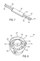
FIG. 7 is a cross-sectional view of the exemplary end cap assembly of FIG. 6 taken about line 7-7; and
FIG. 8 is a perspective view of still another exemplary end cap assembly in accordance with the invention;
DETAILED DESCRIPTION
The principles of the present application have particular application to filtration assemblies for hydraulic systems, for example for aircrafts, construction equipment, etc., and thus will be described below chiefly in this context. It will of course be appreciated, and also understood, that the principles of the invention may be useful in other applications where filtration of contamination from fluid is desired.
Turning now to FIG. 1, a filtration assembly is shown at reference numeral 10. The filtration assembly includes top and bottom end caps 12 and 14 having respective cavities for receiving ends of a filter media 16. The ends of the filter media may be secured in the cavities by a bonding agent, thereby providing a positive retention through adhesion. The filter media may be any suitable media, such as a wire reinforced pleated filter media, and the bonding agent may be any suitable bonding agent, such as an adhesive. The top end cap 12 has a flange 18 having a groove that receives a suitable seal 20, such as an o-ring, to provide positive sealing of the end cap to an adjacent component, such as a filter head. The top end cap 12 may also include a coupling portion, such as threads, to couple to the filter head.
The filtration assembly 10 may be replaced by a filtration assembly 28 according to the present invention, but it will be appreciated that the foregoing description of the filtration assembly 10 is equally applicable to the filtration assembly 28 except as noted below. The filtration assembly 28 includes first and second end caps having respective cavities that receive ends of the filter media 16.
Referring now to FIGS. 2-4, an end cap 30 of the filtration assembly 28, which may replace one or both of the end caps 12 and 14, has a cavity 32 for receiving an end of the filter media 16, an inner wall 34, and an outer wall 36 surrounding the inner wall and spaced therefrom to define the cavity. As shown, the inner and outer walls are annular walls that are concentrically arranged, although it will be appreciated that the walls may be arranged in any suitable manner and may be any suitable shape. The end cap also includes an end wall 38 non-parallel to the inner and outer walls 34 and 36, and in the illustrated embodiment perpendicular to the inner and outer walls, and axially spaced from the ends of the walls adjacent the filter media to define an end wall of the cavity. The end cap may be any suitable material, such as plastic, and may be formed in any suitable manner, such as injection molding.
The end cap 30 may be formed with a groove or the like, as shown in FIG. 1, which receives a seal 20 to seal the end cap to a filter head. The end cap 30 can also include one or more tangs 40 on an outer surface of the outer wall. The one or more tangs provide grip for an operator when securing the end cap to the filter media.
As best shown in FIG. 4, the inner wall 34 defines a passage 42 through the end cap for fluid, such as air or hydraulic fluid, to flow through the end cap. If the filtration assembly is an outside-in assembly, fluid flows from outside the filter media 16, through the filter media and out through the passage 42. If the filtration assembly is an inside-out assembly, fluid flows through the passage 42 in a top and/or bottom end cap, to an interior portion of the filter media 16 and then out through the filter media. In some applications, the filter media may be surrounded by a cylinder that prevents the filter media from being blown radially outwardly by internal pressure. The internal pressure will also attempt to separate the end caps from the filter element.
To prevent separation, at least one retainer 50 is provided that is mechanically locked to the end cap in the cavity and that defines a region into which the bonding agent that secures the filter media 16 can flow to form a mechanical interlock with the retainer. The retainer 50 may be any suitable material, such as steel and may have any suitable shape, such as a ring, a spool with a flange providing the mechanical lock and a flange providing the mechanical interlock, etc. The retainer 50 has a body 52 and at least one tine 54, which may be for example resilient or stiff, and in the illustrated embodiment a plurality of circumferentially spaced tines, projecting from the body to mechanically lock the retainer to the end cap. The tines project radially outwardly from the body and engage an inner surface of the outer wall 36 of the end cap 30 to secure the retainer to the end cap. Specifically, the tines 54 bite into the inner surface of the outer wall 36 to prevent twisting of the retainer.
Each tine 54 defines with an adjacent tine, the body 52 and the inner surface of the outer wall a region 56 into which the bonding agent can flow. The retainer 50 also has a through-hole extending therethrough, which defines with the inner wall 34 a region 58 into which the bonding agent can flow. As shown in FIG. 4, the retainer 50 has a surface facing opposite the filter media, and an open space is defined behind the surface into which the bonding agent can flow. For example, the retainer 50 may be positioned in the cavity 32 in an axially spaced relationship to the end wall 38, thereby defining an undercut 60 in the cavity.
When the bonding agent is introduced into the cavity, the bonding agent flows through the regions 56 and 58 and into the undercut 60 and at least partially fills the cavity 132 such that the retainer 50 is at least partially surrounded by the bonding agent. When the bonding agent cures, the bonding agent is mechanically locked in the undercut 60 to resist failure in tension and mechanically locked in the regions 56 and 68 to resist failure in torsion. Thereby, even if the bonding agent does not fully adhere to the end cap, the filter media will be secured in the end cap via the mechanical interlock of the bonding agent and retainer. This may occur, for example, when the end cap is made of plastic and when the retainer is made of steel, which has a higher surface tension than most plastics.
As should be appreciated, by providing the retainer 50 in the end cap 30, the end cap does not need undercuts machined into the end cap to resist tension failures. This reduces the cost of producing the end caps and reduces the amount of machining required. Providing the retainer 50 in the end cap 30 also allows for an end cap to be used that has walls that are too thin to have undercuts machined into the walls, and allows for a larger locking surface than with an undercut machined into an end cap.
Turning now to FIGS. 5-7, an exemplary embodiment of the filtration assembly is shown at 128. The filtration assembly 128 is substantially the same as the above-referenced filtration assembly 28, and consequently the same reference numerals but indexed by 100 are used to denote structures corresponding to similar structures in the filtration assemblies. In addition, the foregoing description of the filtration assembly 28 is equally applicable to the filtration assembly 128 except as noted below.
Referring now to FIGS. 5-7, an end cap 130 of the filtration assembly 128 has a cavity 132 for receiving an end of the filter media 16, an inner wall 134, and an outer wall 136 surrounding the inner wall and spaced therefrom to define the cavity. The end cap also includes an end wall 138 non-parallel to the inner and outer walls 134 and 136, and in the illustrated embodiment perpendicular to the inner and outer walls, and axially spaced from the ends of the walls adjacent the filter media to define an end wall of the cavity. The end wall 138 is shown as the outer wall of the end cap, similar to the end cap 14 of FIG. 1, but it will be appreciated that the end cap 130 may be provided with a flanged portion extending past the end wall 138 for coupling to a filter head as shown in FIGS. 2-4. It will also be appreciated that the filtration assemblies may include ends caps having any suitable shape. For example, a filtration assembly may include a top end cap shaped like the end cap 30 and a bottom end cap shaped like the end cap 130, a top end cap shaped like the end cap 130 and a bottom end cap shaped like the end cap 30, top and bottom end caps shaped like either of the end caps 30 or 130, etc.
To prevent separation of the end caps from the filter media, a plurality of retainers 150 are provided that are mechanically locked to the end cap in the cavity and that define a region into which the bonding agent that secures the filter media 16 can flow to form a mechanical interlock with the retainer. The retainers 150 are circumferentially arranged around the cavity 132 between the inner wall 134 and the outer wall 136. The retainers 150 each have a body 152 and at least one tine 154, and in the illustrated embodiment a plurality of circumferentially spaced tines, projecting from the body to mechanically lock the retainer to the end cap. The tines project radially outwardly from the body and at least one tine engages an inner surface of the outer wall 136 of the end cap 130 and at least one tine engages an outer surface of the inner wall 134 to secure the retainer to the end cap.
As illustrated, each retainer 150 has two tines 154 that bite into the inner surface of the outer wall 136 and two tines that bite into the outer surface of the inner wall 134, although it will be appreciated that any suitable number of retainers may bite into the walls. The tines 154 that bite into the outer wall define with one another, the body 152 and the inner surface of the outer wall a region 156 into which the bonding agent can flow. Similarly, the tines 154 that bite into the inner wall define with one another, the body 152 and the outer surface of the inner wall a region 157 into which the bonding agent can flow. The retainers 150 also include through-holes extending therethrough that provide a region 158 into which the bonding agent can flow
As shown in FIG. 7, the retainers 150 have a surface facing opposite the filter media, and open spaces are defined behind the surfaces into which the bonding agent can flow. For example, the retainer 150 may be positioned in the cavity 132 in an axially spaced relationship to the end wall 138, thereby defining an undercut 160 in the cavity. When the bonding agent is introduced into the cavity, the bonding agent flows through the regions 156, 157 and 158, as well as into regions 159 between the retainers 150, and into the undercut 160 to surround both sides of the retainers to mechanically interlock the bonding agent with the retainers.
Turning now to FIG. 8, an exemplary embodiment of the filtration assembly is shown at 228. The filtration assembly 228 is substantially the same as the above-referenced filtration assembly 28, and consequently the same reference numerals but indexed by 200 are used to denote structures corresponding to similar structures in the filtration assemblies. In addition, the foregoing description of the filtration assembly 28 is equally applicable to the filtration assembly 228 except as noted below.
Referring now to FIG. 8, an end cap 230 of the filtration assembly 228 has a cavity 232 for receiving an end of the filter media 16, an inner wall 234, and an outer wall 236 surrounding the inner wall and spaced therefrom to define the cavity. The end cap also includes an end wall 38 non-parallel to the inner and outer walls 34 and 36, and in the illustrated embodiment perpendicular to the inner and outer walls, and axially spaced from the ends of the walls adjacent the filter media to define an end wall of the cavity.
To prevent separation of the end caps from the filter media, at least one retainer 250 is provided that is mechanically locked to the end cap 230 in the cavity and that defines a region into which the bonding agent that secures the filter media 16 can flow to form a mechanical interlock with the retainer. The retainer 250 has a body 252 and at least one tine 254, and in the illustrated embodiment a plurality of circumferentially spaced tines, projecting from the body to mechanically lock the retainer to the end cap. The tines project radially inwardly from the body and engage an outer surface of the inner wall 234 of the end cap 230 to secure the retainer to the end cap. Each tine 254 defines with an adjacent tine, the body 252 and the outer surface of the inner wall a region 256 into which the bonding agent can flow. The retainer 250 is sized such that an outer diameter of the retainer is less than an inner diameter of the outer wall 236, thereby defining with the outer wall a region 258 into which the bonding agent can flow.
Although the invention has been shown and described with respect to a certain embodiment or embodiments, it is obvious that equivalent alterations and modifications will occur to others skilled in the art upon the reading and understanding of this specification and the annexed drawings. In particular regard to the various functions performed by the above described elements (components, assemblies, devices, compositions, etc.), the terms (including a reference to a “means”) used to describe such elements are intended to correspond, unless otherwise indicated, to any element which performs the specified function of the described element (i.e., that is functionally equivalent), even though not structurally equivalent to the disclosed structure which performs the function in the herein illustrated exemplary embodiment or embodiments of the invention. In addition, while a particular feature of the invention may have been described above with respect to only one or more of several illustrated embodiments, such feature may be combined with one or more other features of the other embodiments, as may be desired and advantageous for any given or particular application.

Claims (20)

What is claimed is:
1. A filtration assembly including:
at least one end cap having a cavity defined therein;
a filter media having one end disposed in the cavity and secured to the end cap by a bonding agent; and
at least one retainer mechanically locked to the end cap in the cavity and defining a region into which the bonding agent can flow to form a mechanical interlock with the retainer, the at least one retainer having a body and a plurality of circumferentially spaced tines projecting from the body to bite into a wall of the end cap to mechanically lock the retainer to the end cap to prevent twisting of the retainer relative to the end cap.
2. The filtration assembly according to claim 1, wherein the plurality of tines project radially outwardly from the body and engage an inner surface of the wall of the end cap to secure the retainer to the end cap.
3. The filtration assembly according to claim 2, wherein a pair of the circumferentially spaced tines, the body of the retainer, and the inner surface define respective regions into which the bonding agent can flow.
4. The filtration assembly according to claim 1, wherein the body of the at least one retainer has a through-hole extending therethrough through which the bonding agent can flow.
5. The filtration assembly according to claim 1, wherein the end cap includes an annular inner wall and an annular outer wall surrounding the inner wall, the inner and outer walls defining the cavity.
6. The filtration assembly according to claim 5, wherein the end cap includes an end wall non-parallel to the inner and outer walls and axially spaced from ends of the inner and outer walls that receive the filter media.
7. The filtration assembly according to claim 6, wherein the end wall is perpendicular to the inner wall and the outer wall.
8. The filtration assembly according to claim 6, wherein the retainer is positioned in the cavity in an axially spaced relationship to the end wall, thereby defining an undercut in the cavity for receiving the bonding agent.
9. The filtration assembly according to claim 8, wherein the retainer has an inner diameter that is greater than an outer diameter of the inner wall thereby defining with the inner wall a region into which the bonding agent can flow.
10. The filtration assembly according to claim 5, wherein the plurality of tines project radially inwardly from the body and engage an outer surface of the inner wall of the end cap to secure the retainer to the end cap.
11. The filtration assembly according to claim 10, wherein a pair of the circumferentially spaced tines, the body of the retainer, and the outer surface define respective regions into which the bonding agent can flow.
12. The filtration assembly according to claim 10, wherein the retainer has an outer diameter that is less than an inner diameter of the annular outer wall thereby defining with the outer wall a region into which the bonding agent can flow.
13. The filtration assembly according to claim 10, wherein the end cap includes an end wall non-parallel to the inner and outer walls and axially spaced from ends of the inner and outer walls that receive the filter media, and wherein the retainer is positioned in the cavity in an axially spaced relationship to the end wall, thereby defining an undercut in the cavity for receiving the bonding agent.
14. The filtration assembly according to claim 13, wherein the end wall is perpendicular to the inner wall and the outer wall.
15. The filtration assembly according to claim 5, wherein the inner wall defines a passage through the end cap for fluid.
16. The filtration assembly according to claim 1, wherein the retainer has a surface facing opposite the filter media, and wherein an open space is defined behind the surface into which the bonding agent can flow.
17. The filtration assembly according to claim 1, further comprising:
a second end cap having a cavity defined therein; and
at least one retainer mechanically locked to the second end cap in the cavity and defining a region into which the bonding agent can flow to form a mechanical interlock with the retainer;
wherein a second end of the filter media is disposed in the cavity and secured to the end cap by a bonding agent.
18. The filtration assembly according to claim 1, wherein the bonding agent at least partially fills the cavity such that the at least one retainer is at least partially surrounded by the bonding agent to form the mechanical interlock.
19. A method of forming a filtration assembly including:
top and bottom end caps having respective cavities for receiving ends of a filter media secured to the end caps by a bonding agent, the method including:
inserting at least one retainer having a body and a plurality of circumferentially spaced tines projecting from the body in each cavity;
introducing a bonding agent into each cavity; and
inserting the ends of the filter media into the respective cavities;
wherein the retainers are each mechanically locked to the respective end cap in the respective cavity by the tines biting into a wall of the respective end cap and the retainers each define a region into which the bonding agent can flow to form a mechanical interlock with the retainer.
20. A filtration assembly including:
at least one end cap having a cavity defined therein;
a filter media having one end disposed in the cavity and secured to the end cap by a bonding agent; and
at least one retainer that is mechanically locked to the end cap in the cavity and defines a region into which the bonding agent can flow to form a mechanical interlock with the retainer, the region being defined by at least one through-hole that extends through the retainer to a chamber located below the at least one retainer,
wherein the bonding agent flows through the through-hole and into the chamber located below the at least one retainer, the bonding agent at least partially filling the cavity such that the at least one retainer is at least partially surrounded by the bonding agent to form the mechanical interlock, the retainer being mechanically locked to the end cap independently of the bonding agent.
US14/375,920 2012-02-02 2012-05-18 End cap retention device Active 2033-11-11 US9925480B2 (en)

Priority Applications (1)

Application Number Priority Date Filing Date Title
US14/375,920 US9925480B2 (en) 2012-02-02 2012-05-18 End cap retention device

Applications Claiming Priority (3)

Application Number Priority Date Filing Date Title
US201261594006P 2012-02-02 2012-02-02
US14/375,920 US9925480B2 (en) 2012-02-02 2012-05-18 End cap retention device
PCT/US2012/038474 WO2013115837A1 (en) 2012-02-02 2012-05-18 End cap retention device

Publications (2)

Publication Number Publication Date
US20150021256A1 US20150021256A1 (en) 2015-01-22
US9925480B2 true US9925480B2 (en) 2018-03-27

Family

ID=46229920

Family Applications (1)

Application Number Title Priority Date Filing Date
US14/375,920 Active 2033-11-11 US9925480B2 (en) 2012-02-02 2012-05-18 End cap retention device

Country Status (4)

Country Link
US (1) US9925480B2 (en)
EP (1) EP2809424B1 (en)
ES (1) ES2774208T3 (en)
WO (1) WO2013115837A1 (en)

Families Citing this family (4)

* Cited by examiner, † Cited by third party
Publication number Priority date Publication date Assignee Title
JP6554308B2 (en) * 2015-04-17 2019-07-31 ローム株式会社 Bus controller, power supply, and power adapter
JP2019506287A (en) * 2015-11-16 2019-03-07 スパーク イノベーション、エルエルシー Appliances for homemade personal care products and household cleaners
USD865484S1 (en) * 2017-08-15 2019-11-05 ZH Brothers International, Inc. 30 amp 90 degree twist lock
US20220410058A1 (en) * 2021-06-24 2022-12-29 The Sy-Klone Company, Llc Self-cleaning air filtration apparatus and method

Citations (15)

* Cited by examiner, † Cited by third party
Publication number Priority date Publication date Assignee Title
US3457339A (en) * 1965-12-08 1969-07-22 Pall Corp Process for making end capped filter elements
US4521309A (en) * 1980-07-14 1985-06-04 Pall Corporation Filter cartridge with castellated support and process of making the same
US5381709A (en) 1993-06-14 1995-01-17 Louw; John A. Application tool for torque-controlled fastening system
US6039525A (en) 1998-10-21 2000-03-21 Johnson; H. Thad Integrated spring ring retainer for captivating a fastener to a workpiece
US6171482B1 (en) 1998-05-11 2001-01-09 Bret E. Nichols Self-aligning reusable liquid filtering system
US6500335B2 (en) 2000-02-16 2002-12-31 Stanadyne Corporation Filter system base module with self-locking cartridge retainer
US20060196823A1 (en) * 2005-03-03 2006-09-07 Arvin Technologies, Inc. Filter media-to-plastic adhesion method and apparatus
US7198152B2 (en) 2003-04-15 2007-04-03 Lincoln Global, Inc. Welding wire container with ribbed walls and mating retainer ring
DE202006011989U1 (en) 2006-08-03 2007-12-20 Mann + Hummel Gmbh Air filter element with covered end plates
WO2008015092A1 (en) 2006-08-03 2008-02-07 Mann+Hummel Gmbh Air filter element with transparent end plates and production method
US20080047891A1 (en) * 2006-08-25 2008-02-28 Mann & Hummel Gmbh Liquid filter suitable for motor vehicles
US20080302476A1 (en) 2007-06-08 2008-12-11 Filtrex Holdings Pte Ltd. Method to bond plastic end caps to porous filtration bodies
US7628837B2 (en) 2005-10-19 2009-12-08 Baldwin Filters, Inc. Air filter with composite end cap
US20100148448A1 (en) 2008-12-12 2010-06-17 Pradeep Pinto Pump seal
US20150165350A1 (en) 2007-08-28 2015-06-18 PECOFacet (Houston), LLC Pleated Woven Wire Filter

Patent Citations (15)

* Cited by examiner, † Cited by third party
Publication number Priority date Publication date Assignee Title
US3457339A (en) * 1965-12-08 1969-07-22 Pall Corp Process for making end capped filter elements
US4521309A (en) * 1980-07-14 1985-06-04 Pall Corporation Filter cartridge with castellated support and process of making the same
US5381709A (en) 1993-06-14 1995-01-17 Louw; John A. Application tool for torque-controlled fastening system
US6171482B1 (en) 1998-05-11 2001-01-09 Bret E. Nichols Self-aligning reusable liquid filtering system
US6039525A (en) 1998-10-21 2000-03-21 Johnson; H. Thad Integrated spring ring retainer for captivating a fastener to a workpiece
US6500335B2 (en) 2000-02-16 2002-12-31 Stanadyne Corporation Filter system base module with self-locking cartridge retainer
US7198152B2 (en) 2003-04-15 2007-04-03 Lincoln Global, Inc. Welding wire container with ribbed walls and mating retainer ring
US20060196823A1 (en) * 2005-03-03 2006-09-07 Arvin Technologies, Inc. Filter media-to-plastic adhesion method and apparatus
US7628837B2 (en) 2005-10-19 2009-12-08 Baldwin Filters, Inc. Air filter with composite end cap
DE202006011989U1 (en) 2006-08-03 2007-12-20 Mann + Hummel Gmbh Air filter element with covered end plates
WO2008015092A1 (en) 2006-08-03 2008-02-07 Mann+Hummel Gmbh Air filter element with transparent end plates and production method
US20080047891A1 (en) * 2006-08-25 2008-02-28 Mann & Hummel Gmbh Liquid filter suitable for motor vehicles
US20080302476A1 (en) 2007-06-08 2008-12-11 Filtrex Holdings Pte Ltd. Method to bond plastic end caps to porous filtration bodies
US20150165350A1 (en) 2007-08-28 2015-06-18 PECOFacet (Houston), LLC Pleated Woven Wire Filter
US20100148448A1 (en) 2008-12-12 2010-06-17 Pradeep Pinto Pump seal

Non-Patent Citations (2)

* Cited by examiner, † Cited by third party
Title
International Preliminary Report on Patentability for corresponding patent application No. PCT/US2012/038474 dated May 7, 2014.
International Search Report for corresponding patent application No. PCT/US2012/038474 dated Oct. 26, 2012.

Also Published As

Publication number Publication date
EP2809424A1 (en) 2014-12-10
EP2809424B1 (en) 2020-01-08
ES2774208T3 (en) 2020-07-17
US20150021256A1 (en) 2015-01-22
WO2013115837A1 (en) 2013-08-08

Similar Documents

Publication Publication Date Title
US9925480B2 (en) End cap retention device
CN101861193B (en) Fluid filter system
US10774798B2 (en) Fuel water separator filter
US9446333B2 (en) Keyed thread engagement on spin-on filter element
US20140183118A1 (en) Slip thread locking head with interactive element
US20180133627A1 (en) No filter no run fluid filtration system
KR102240601B1 (en) Keyed thread engagement on spin-on filter element
DE112018000345T5 (en) Easy-change filter that uses a snap closure
US20160010714A1 (en) Damping valve
CN113226515A (en) Integrated multifunctional end cover sealing component
EP0756669A1 (en) Sealing arrangement for injection valves on fuel feed lines
EP3420253B1 (en) Engine component comprising a seal
AU2020297963B2 (en) Filter element having potted gasket end cap assembly
KR20110007572A (en) Engine oil strainer
WO2014145505A2 (en) Engine spacer plate gasket
US11173436B2 (en) Connector assembly, filter assembly, filter device, and method of use
US20180221797A1 (en) No Filter No Run Fluid Filtration System
EP3185980A1 (en) Filter cartridge interface
DE102014103314A1 (en) Abgasrohrflansch
CN218063474U (en) Valve assembly and valve cage for valve assembly
CN207740111U (en) The energy accumulator main body and accumulator package of accumulator package in engine pack
JP3187841U (en) Oil filter
DE102022106933A1 (en) Filter element, filter element unit and filter
US20180369733A1 (en) Filter Element With Endcap Having Rigid Reinforcing Member
DE102014003627A1 (en) radial seal

Legal Events

Date Code Title Description
AS Assignment

Owner name: PARKER-HANNIFIN CORPORATION, OHIO

Free format text: ASSIGNMENT OF ASSIGNORS INTEREST;ASSIGNORS:LUTHER, KENNETH M.;SEXSMITH, MICHAEL R.;REEL/FRAME:033442/0694

Effective date: 20140728

STCF Information on status: patent grant

Free format text: PATENTED CASE

AS Assignment

Owner name: PARKER INTANGIBLES, LLC, OHIO

Free format text: ASSIGNMENT OF ASSIGNORS INTEREST;ASSIGNOR:PARKER-HANNIFIN CORPORATION;REEL/FRAME:045843/0859

Effective date: 20180405

MAFP Maintenance fee payment

Free format text: PAYMENT OF MAINTENANCE FEE, 4TH YEAR, LARGE ENTITY (ORIGINAL EVENT CODE: M1551); ENTITY STATUS OF PATENT OWNER: LARGE ENTITY

Year of fee payment: 4