US9923350B1 - System and apparatus for providing functional and decorative electrical cover plates - Google Patents
System and apparatus for providing functional and decorative electrical cover plates Download PDFInfo
- Publication number
- US9923350B1 US9923350B1 US15/290,662 US201615290662A US9923350B1 US 9923350 B1 US9923350 B1 US 9923350B1 US 201615290662 A US201615290662 A US 201615290662A US 9923350 B1 US9923350 B1 US 9923350B1
- Authority
- US
- United States
- Prior art keywords
- plate
- electrical
- assembly
- back plate
- flange
- Prior art date
- Legal status (The legal status is an assumption and is not a legal conclusion. Google has not performed a legal analysis and makes no representation as to the accuracy of the status listed.)
- Active
Links
Images


Classifications
-
- H—ELECTRICITY
- H02—GENERATION; CONVERSION OR DISTRIBUTION OF ELECTRIC POWER
- H02G—INSTALLATION OF ELECTRIC CABLES OR LINES, OR OF COMBINED OPTICAL AND ELECTRIC CABLES OR LINES
- H02G3/00—Installations of electric cables or lines or protective tubing therefor in or on buildings, equivalent structures or vehicles
- H02G3/02—Details
- H02G3/08—Distribution boxes; Connection or junction boxes
- H02G3/14—Fastening of cover or lid to box
-
- H—ELECTRICITY
- H02—GENERATION; CONVERSION OR DISTRIBUTION OF ELECTRIC POWER
- H02G—INSTALLATION OF ELECTRIC CABLES OR LINES, OR OF COMBINED OPTICAL AND ELECTRIC CABLES OR LINES
- H02G3/00—Installations of electric cables or lines or protective tubing therefor in or on buildings, equivalent structures or vehicles
- H02G3/02—Details
- H02G3/08—Distribution boxes; Connection or junction boxes
- H02G3/081—Bases, casings or covers
- H02G3/083—Inlets
-
- H—ELECTRICITY
- H02—GENERATION; CONVERSION OR DISTRIBUTION OF ELECTRIC POWER
- H02G—INSTALLATION OF ELECTRIC CABLES OR LINES, OR OF COMBINED OPTICAL AND ELECTRIC CABLES OR LINES
- H02G3/00—Installations of electric cables or lines or protective tubing therefor in or on buildings, equivalent structures or vehicles
- H02G3/02—Details
- H02G3/08—Distribution boxes; Connection or junction boxes
- H02G3/12—Distribution boxes; Connection or junction boxes for flush mounting
Definitions
- the disclosure relates generally to a system and apparatus for electrical switch and outlet plate covers and more particularly to a system and apparatus for providing decorative and functional electrical switch and outlet plate covers.
- Electrical cover plates those used to cover electrical outlet boxes and switch boxes used in buildings, homes and other structures have been around since the advent of the availability of electrical power for homes, businesses and commercial buildings. They are typically made of plastic-like material or sometimes metal. They attach to the electrical box, be it an outlet box or switch box with screws that are inserted through screw holes in the cover plate. The screw holes in the cover plate line up with screw receptacles in the electrical box. The electrical cover plates have apertures in them that allow the plate to surround the outlets in an outlet box and the switch or switches in an electrical switch box.
- the electrical cover plates cover the entire electrical box shielding those using the outlets or switches from the electrical wiring in the electrical box. Electrical cover plates thus provide an important safety function.
- an electrical wall box plate cover assembly has: a) a back plate configured to attach to an electrical wall box; b) a center plate configured to connect to the back plate with a connection and aligning mechanism; c) a front plate configured to connect to the back plate with the connection and aligning mechanism; d) wherein when the back plate, the center plate and the front plate are attached together with the connection and aligning mechanism, electrical interface apertures located on the front plate, the center plate and the back plate are aligned together, and thus allow access to an electrical system interface device; e) wherein the front plate consists of a clean, light transparent material and the center plate can be configured with art work; f) the base plate, the center plate and the front plate each have an extended portion; g) the connection and aligning mechanism comprises: 1) screw holes on each of the plates that when the screw holes on each plate are aligned, the plates can be attached to an electrical interface outlet; and 2) the base plate having a securing and aligning structure to
- the center plate is provided with a surface to accept art work which can be viewed through the cover plate when the back plate, center plate and front plate are connected together with the securing mechanism.
- artwork can be added to the cover plate.
- artwork can be added to the cover plate by etching the cover plate.
- the electrical wall box plate assembly of claim 1 wherein the detachable connecting mechanism to detachably connect the extended portion of the back plate to a wall comprises a tab channel on the extended portion of the back plate wherein the tab channel can accommodate a first surface of a tab with adhesive on the first surface and adhesive on an opposite second surface of the tab, which second surface can be placed against a wall to secure the extended portion to the wall.
- the electrical wall box plate assembly plate assembly it can be configured with an aperture for an electrical wall box containing electrical interface devices for electrical switches, electrical outlets and a combination of a switches and outlets.
- the securing and aligning structure on the back plate is first flanged gripper located on a top edge of the base plate and projecting out from the base plate and a mirror image second flange gripper on a bottom edge of the back plate opposite the first flange gripper; and b) the front plate engaging portion consists of a first flange projecting from a backside of the front plate adjacent its top edge and a mirror image second flange projecting from the backside of the front plate adjacent a bottom edge of the front plate, the first and second flange being positioned such that when the back side of the front plate faces the back plate and the screw holes of the front plate and the back plate are aligned the first flange of the front plate aligns with the first flange gripper and the second flange aligns with the second flange gripper and first and second flanges can detachably engage the first and second flange grippers.
- the back plate has at least one positioning and aligning structure that together with a position and aligning structure on an auxiliary back plate aligns the back plate and the auxiliary back plate such that when the plates are aligned together on a wall they form a predetermined configuration on the wall.
- the at least one positioning and aligning structure on the back plate is a detent and the positioning and aligning structure on the auxiliary plate is a projection that mates with the detent.
- the extended area of the base plate assembly when covering an electrical box can project from the electrical box in in a direction selected from the group consisting of up, down left or right. It is note that base plate assembly and primary plate assembly are used synonymously.
- the disclosure provides a functional and decorative wall plate configuration having: a) a primary plate assembly that covers an electrical wall box interface; and b) at least one auxiliary plate assembly that interconnects through a plate interconnecting apparatus to the primary plate assembly such that when the primary plate assembly is attached to a wall and covering an electrical interface box the at least one auxiliary plate assembly can be positioned in a predetermined position adjacent to the base plate assembly to provide a predetermined configuration on the wall.
- the interconnecting apparatus includes at least one detent on a back plate of the primary plate assembly and at least one projection on a back plate of the at least one auxiliary plate assembly.
- the primary plate assembly includes the back plate, a center plate and a front plate, and the back plate, the center plate and the front plate are connected together by an interconnect mechanisms on the back and front plate.
- the auxiliary plate assembly has of the back plate, a center plate and a front plate, and the back plate, the center plate and the front plate are connected together by an interconnect mechanism on the back and front plate.
- the electrical wall box interface is can be a switch box, an outlet box of a combination of a switch-outlet box.
- the auxiliary plate assembly can be a picture frame, a key holder, a note holder or a design pattern holder.
- an electrical wall box plate cover assembly having: a) a back plate configured to attach to an electrical wall box; b) a center plate configured to connect to the back plate with a connection and aligning mechanism; c) a front plate configured to connect to the back plate with the connection and aligning mechanism; d) wherein when the back plate, the center plate and the front plate are attached together with the connection and aligning mechanism, electrical interface apertures located on the front plate, the center plate and the back plate are aligned together, and thus allow access to an electrical system interface device; and f) the connection and aligning mechanism includes: 1) screw holes on each of the plates that when the screw holes on each plate are aligned, the plates can be attached to an electrical interface outlet; and 2) the base plate having a securing and aligning structure to secure the center plate and connect to an engaging portion of the front plate to connect the front plate to the back plate with the center plate there between.
- the securing and aligning structure on the back plate is first flanged gripper located on a top edge of the base plate and projecting out from the base plate and a mirror image second flange gripper on a bottom edge of the back plate opposite the first flange gripper; and b) the front plate engaging portion includes a first flange projecting from a backside of the front plate adjacent its top edge and a mirror image second flange projecting from the backside of the front plate adjacent a bottom edge of the front plate, the first and second flange being positioned such that when the back side of the front plate faces the back plate and the screw holes of the front plate and the back plate are aligned the first flange of the front plate aligns with the first flange gripper and the second flange aligns with the second flange gripper and first and second flanges can detachably engage the first and second flange grippers.
- the center plate is provided with a surface to accept art work which can be viewed through the cover plate when the back plate, center plate and front plate are connected together with the securing mechanism; b) wherein the aligned apertures are sized and positioned to accept interface devices selected from a group consisting of: electrical switches, electrical outlets and a combination of electrical switches and electrical outlets; and c) the decorative designs are selected from a group consisting of a letter of the alphabet, a butterfly, a beetle, and a flower.
- the invention provides a method for providing a functional and decorative wall plate configuration having the steps of: a) providing a primary plate assembly that covers an electrical wall box interface; and b) providing at least one auxiliary plate assembly that interconnects through a plate interconnecting apparatus to the base plate assembly such that when the primary plate assembly is attached to a wall and covering an electrical interface box the auxiliary plate assembly can be positioned in a predetermined position adjacent to the base plate assembly to provide a predetermined configuration on the wall.
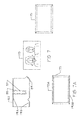
- FIG. 1 is a exploded, staggered view of the plates of the basic plate assembly of the present invention
- FIG. 2 is a view of the fully assembled basic plate assembly of the present invention attached to a wall and covering an electrical switch box;
- FIG. 3 is a cross-sectional view along line III-III of FIG. 2 ;
- FIG. 3A is a perspective view of the back side of the front plate showing the securing flanges on the front plate;
- FIG. 4 is a exploded, staggered view of the plate assembly depicted in FIG. 2 ;
- FIG. 5 is a view of the base wall plates that make up one variation of an articulated auxiliary plate assembly apparatus
- FIG. 6 is an example of a fully assembled articulated auxiliary plate system attached to a wall, in a predetermined configuration adjacent a primary plate assembly;
- FIG. 6A is cross-sectional view of FIG. 6 along line VI-VI;
- FIG. 7 is an exploded, staggered view of an example of an auxiliary plate assembly
- FIG. 7A provides a view of the back of auxiliary front plate 175 ;
- FIG. 8 is a perspective view of an auxiliary wall plate system of the articulated auxiliary wall plate system
- FIG. 9 is a side view along line VII-VII of the plate depicted in FIG. 8 ;
- FIG. 10 is a perspective view of another auxiliary wall plate of the articulated wall plate system.
- FIG. 11 is a side view along line XI-XI of the auxiliary wall plate of FIG. 10 ;
- FIG. 12 is a view of another embodiment of a base plate assembly covering an electrical wall box
- FIG. 12A is an exploded, staggered view of the base plate assembly of FIG. 12 ;
- FIG. 12B is a view of the back of front plate 207 ;
- FIG. 13 is another variation of the invention depicting the switchable plate system.
- FIG. 14 is another example of the switchable plate invention.
- FIG. 15 is another example of the switchable plate variation.
- FIG. 16 is an example of the switchable plate variation configured for an outlet box.
- FIG. 1 provides a staggered, exploded view of the plates of the base plate assembly 21 .
- the assembly includes back plate 23 , center or creative plate 25 and cover or front plate 27 .
- Back plate 23 attaches to the electrical switch box, not shown in in the standard fashion with screws, not shown, through screw holes 29 A and 29 B.
- Center plate 25 fits over back plate 23 and its screw holes 33 A, 33 B and its switch aperture 35 aligns with the screw holes 29 A and 29 B and switch aperture 31 of back plate 23 .
- front plate 27 fits over center plate 25 and its screw holes 37 A and 37 B align with the screw holes of back plate 23 and center plate 25 .
- Front plate 27 switch aperture 39 also aligns with the switch aperture of back plate 23 and front plate 27 .
- the switch When assembled base plate assembly 21 is attached to the electrical switch box, the switch extends through switch apertures 31 of back plate 23 , aperture 35 of center plate 25 and aperture 39 of font plate 27 .
- the example shown herein is using a typical electrical switch box, it can also be used on an electrical outlet box as well as other types of wall boxes such as telephone, cable, etc.
- base plate assembly and primary plate assembly are used synonymously in this disclosure.
- FIG. 1 provides a view of the three plates having projections 41 A, 41 B and 41 C that extends out beyond the electrical box covered by the plates.
- FIG. 2 provides a view of the fully assembled plate assembly 43 mounted on a wall 11 covering an electrical switch box 45 as indicated by the dotted lines since the box is covered by the plates. Also, it should be noted that base plate and back plate are sometimes used interchangeably.
- FIG. 3 is a cross-sectional view of plate assembly 43 along line III-III of FIG. 2 .
- line III-III cuts through the center of two securing tracks 47 A and 47 B on back plate 23 .
- Securing tracks 47 A and 47 B are embodiments of the engaging portion of back plate 23 . Both securing tracks are located opposite each other on the top and bottom edge respectively of back plate 23 and only extend along a limited portion of the top edge and bottom edge of back plate 23 .
- securing tracks 47 A and 47 B are mirror image structures. Track 47 A is formed by projection 48 A that extend off at 90° from the top edge of back plate 23 .
- Extending off of projection 48 A are two parallel flanges 49 A and 49 B.
- securing track 47 B is formed by projection 48 B extending off at 90° from the bottom edge of back plate 23 .
- Extending off of projection 48 B are two parallel flanges 51 A and 51 B.
- Securing track 47 A is made up of projection 48 A and parallel flanges 49 A and 49 B.
- securing track 47 B is made up of projection 48 B and parallel flanges 51 A and 51 B.
- the opposing set of flanges 49 A and 51 A retain center plate 25 which can either be snapped into place or slid into place in the space between flange 49 A and 51 A and the main wall 53 of back plate 23 .
- center plate 25 is snapped into place and screw holes 33 A and 33 B of center plate 25 are aligned with screw holes 29 A and 29 B of back plate 23 both back plate 23 and center plate will become congruent with each other and held in place together once screws are inserted into the screw holes and into the screw receptacles on the electrical box being covered.
- the main body or wall 53 of back plate 23 has a mechanism to hold extended portion 41 A of the back plate in place when the base plate assembly 21 is connected to the electrical box.
- channel 55 provides a place to attach a securing tab 57 to secure extended portion 41 A to the wall, which together with the screws inserted through the respective screw holes of each of the plates holds base plate assembly 21 in place.
- the extended portion 41 A of back plate 23 is stabilized and held in place by an adhesive tab 57 , which is placed in channel 55 .
- Tab 57 is a thick tape with adhesive on both sides of the tape, one side adhering to channel 55 and the second side detachably connecting to the wall.
- the preferred embodiment of the invention uses as tab 57 CommandTM adhesive tab that has adhesive surface on both sides.
- CommandTM is a trademark of 3M Company which manufactures the tabs.
- When installing the base plate system tab 57 is initially secured in channel 55 . Then when the plate assembly 21 is attached to the wall the exposed second adhesive surface of the CommandTM adhesive tab secures it to the wall.
- tab 57 is an embodiment of a detachable connecting mechanism.
- FIG. 3A provides a view of the backside of front plate 27 , which has two securing flanges of 63 A and 63 B.
- Securing flanges 63 A and 63 B are one embodiment of the engaging portion of front plate 27 .
- front plate 27 is connected to back plate 23 securing flange 63 A lines up with securing track 47 A and securing flange 63 B lines up with securing track 47 B.
- Both securing flanges 63 A and 63 B are L-shaped. Referring to FIG. 3 , securing flange 63 A fits into channel 65 A of securing track 47 A and securing flange 63 B fits into channel 65 B of securing track 47 B.
- the securing flanges 63 A and 63 B can be slid into the channels 65 A and 65 B or they can be snapped on.
- channel 65 A is formed by flange 49 A and 49 B on our projection 48 A.
- channel 65 B is formed by flange 51 A and 51 B on projection 48 B.
- Any flexible resilient material capable of holding its shape can be used to make the plate systems of the present invention.
- Plastic like, composite material or flexible metal are the preferred materials.
- the flexibility of the material allows for either method of engaging the securing flanges 63 A and 63 B on front plate 27 to securely fit into securing tracks 47 A and 47 B of back plate 23 namely snapping front plate into place by aligning flanges 63 A and 63 B on front plate 27 with flanges 49 B and 51 B on back plate 23 and pushing front plate 27 against back plate 23 .
- FIG. 4 is a staggered exploded view of the variation 43 of the base plate assembly with artwork added to center plate 71 , an image of a fish 66 , and images of aquatic plants 67 etched onto front plate 73 .
- Front plate 73 in this embodiment of the invention is made of a clean plastic or glass-like material onto which images or designs can be etched or painted.
- FIG. 2 as noted above provides a view of base plate assembly 43 fully assembled and attached to a wall and covering an electrical switch box, not visible but is indicated by outline 45 .
- FIG. 5 provides an exploded perspective view of the back plates of an articulated auxiliary back plate configuration 75 of the present invention.
- back plate 23 which covers an electrical box acts as the anchor plate of the back plate configuration 75 .
- Back plate 23 in the embodiment of the invention depicted has on its sides or edges securing and positioning detent grooves 77 A, 77 B, 77 C, 77 D, 77 E and 77 F.
- Auxiliary back plates 81 and 82 have on their edges or sides their own detent grooves, namely detent grooves 84 A, 84 B and 84 C on auxiliary back plate 81 and detent grooves 85 on plate 82 .
- Auxiliary back plates 81 , 82 and 83 each have on their sides or edges linking projections 87 , 88 and 89 respectively. Linking projections 87 , 88 and 89 fit into the detent grooves. Additionally, each of the auxiliary back plates 81 , 82 and 83 each has their own channel for a securing tab namely channel 55 . The channel is shown in outline form since it is on the reverse side of each plate, on the side of the plate that faces the wall. Double sided adhesive tape 57 , also in outline, is positioned in channel 55 of each plate.
- an articulated plate configuration based on back plate 23 and the auxiliary back plates 81 , 82 and 83 interconnected using the detent groove and linking projection mechanism can be formed on the wall around the back plate 23 .
- the auxiliary plates are held in place by securing tabs 57 secured in the respective adhesive tab grooves namely channel 55 , of auxiliary base plates 81 , 82 and 93 83 .
- the projections together with detents or dent groves form a plate interconnecting apparatus.
- FIG. 5 an articulated plate configuration based on back plate 23 and the auxiliary back plates 81 , 82 and 83 interconnected using the detent groove and linking projection mechanism can be formed on the wall around the back plate 23 .
- the auxiliary plates are held in place by securing tabs 57 secured in the respective adhesive tab grooves namely channel 55 , of auxiliary base plates 81 , 82 and 93 83 .
- Each of the auxiliary back plates 81 , 82 and 83 have a securing mechanism that allows for the attaching of a center plate and cover or front plate to them.
- the center and cover plates being designed to accept art work or provide other features as described below.
- FIG. 6 provides a view of a fully assembled articulated plate system 101 mounted on a wall 112 in which the base plate assembly of FIG. 2 alternatively identified as primary plate assembly 69 appears in FIG. 6 and fully assembled auxiliary plate systems 103 , 105 and 107 are included.
- auxiliary plate assemblies 105 and 107 provide picture frames in which pictures can be placed.
- Auxiliary plate assembly 103 provides a decorative pattern. The decorative pattern depicted in FIG. 6 is just one predetermined configuration in which the auxiliary plate assembles are positioned in a predetermined position adjacent the primary plate assembly 69 .
- FIG. 7 provides an exploded view of auxiliary plate assembly 107 . It consists of back plate 83 , center plate 173 and front plate 175 . Back plate 83 as previously noted has detent projection 89 to interlink it with an adjacent auxiliary back plate 81 as depicted in FIG. 5 or alternatively to the back plate of the base plate assembly not depicted. Base plate 83 also has a channel 55 for an adhesive tab 57 to help secure it to the wall as described above.
- auxiliary plate assembly in the embodiment of the invention depicted, back plate 83 , center plate 173 and front plate 175 connect together with the same structure and mechanism as base plate assembly 21 with two notable exceptions.
- First auxiliary plate assemblies do not have screw holes and do not use screws to connect, and the flange based interlocking system between the three plates depicted in FIG. 3 as will be discussed below extends along the entire length of the entire top and bottom edges of back plate 83 and front plate 175 .
- FIG. 6A is a cross-sectional view of auxiliary plate assembly 107 along line VI-VI of FIG. 6 .
- FIG. 6A is compared with FIG. 3 it will be noted they are the same. The only difference is that the securing tracks 191 A and 191 B on the base auxiliary plate 83 as seen in FIGS. 5 and 7 extend across the entire bottom and top edge of back auxiliary plate 83 .
- securing tracks 47 A and 47 B only extend across a portion of back plate 23 .
- Securing flanges 63 A and 63 B only extend across a portion of the back side of front plate 27 .
- FIG. 3A Securing flanges 63 A and 63 B only extend across a portion of the back side of front plate 27 .
- FIG. 3A Securing flanges 63 A and 63 B only extend across a portion of the back side of front plate 27 .
- FIG. 7A a view of the reverse side of auxiliary front plate 175 , securing flange 193 A at the top of the plate, and securing flange 193 B at the bottom of the plate run across the entire top and bottom of the plate.
- securing tracks 191 A and 191 B run across the entire top and bottom respectively.
- FIG. 6A when the plates are joined securing flange 193 A of of front plate 175 engages securing track 191 A of auxiliary back plate 83 and securing flange 193 B of front plate 175 engages securing track 191 B of auxiliary back plate 83 .
- securing tracks 191 A and 191 B and securing flanges 193 A and 193 B other than extending along the entire top and bottom portion of the back and front, the plates have the same structure and function as securing tracks 47 A and 47 B and securing flanges 63 A and 63 B.
- the balances of the reference numbers on FIG. 6A are the same as those on FIG. 3 since they have the same function. Consequently, securing track 191 A is formed by projection 48 A that extends off at 90° from the top edge of plate 83 , and two parallel flanges 49 A and 49 B, extending off of projection 48 B.
- securing track 191 B it is formed by projection 48 B extending off of the bottom edge of plate 83 at 90° with two parallel flanges 51 A and 51 B extending off of projection 48 B.
- L shaped securing flange 193 A is at the top and L shaped securing flange 193 B is at the bottom
- auxiliary plate assembly 107 is a picture frame.
- FIG. 7 depicts an exploded view of plate assembly 107 .
- Center plate 173 provides a surface to attach the picture 195 .
- glue or double-sided adhesive tape is used to attach the picture to center plate 173 .
- Front plate 175 can consist of a clean sheet that covers the entire picture or simply a frame that holds the edges. Additionally, various other mechanical means not shown can be used to secure the picture in the auxiliary plate system.
- FIG. 8 is another example of an auxiliary plate system 111 which provides key ring hooks 113 and 114 . It also includes a removable finial 115 that not only adds a decorative touch, but can also be used to snap the cover plate 117 and center plate 119 free from back plate 121 of the auxiliary plate assembly 123 . Detent linking projection 125 can also be seen which fits into a detent groove on a plate assembly which would be located below it on the wall 127 .
- FIG. 9 is a cross-sectional view of plate 123 FIG. 8 along line VII-VII. Given the view of plate 123 , key hook 114 is visible. Also, linking projection 125 , attached to back plate 121 below on the wall 127 .
- FIG. 10 is a perspective view of another variation of an auxiliary plate system 141 of the present invention.
- Auxiliary plate system 141 consists of cover plate 143 , center plate 145 and back plate 147 .
- Cover plate 143 includes a pen or pencil pocket or holder 149 , a sticky note pocket 153 to hold the sticky notepad (sticky note being the generic name for Post-It® notes [3m]) and a sticky note area 151 to put a sticky note on which a message or note has been written. It also includes a removable finial 115 to pry the plates apart when they need to be disassembled.
- Back plate 147 also has a linking tab 155 .
- FIG. 11 provides a side view of auxiliary plate system 141 along lines XI-XI of FIG. 11 , attached to a wall 157 .
- FIG. 12 depicts another variation of the plate system of the present invention that utilizes the triple plate interconnecting feature of the present invention.
- FIG. 12 is a fully assembly triple plate system 201 .
- FIG. 12A provides an exploded, staggered view of the three plates, namely the back plate 203 , the center plate 205 and the cover or front plate 207 .
- the securing tracks 209 A, 209 B and 209 C are visible.
- securing flanges 211 A, 211 and 211 C are visible on the reverse side of front or cover plate 207 .
- the securing track 209 A, 209 B and 209 C on back plate 203 are the same as those depicted in FIGS. 3 and 6A .
- the securing flanges 211 A, 211 B and 211 C on front plate 207 are the same as those depicted in FIG. 6A .
- plates 203 , 205 and 207 can be connected the same as the other plate assemblies. Once triple plate assembly 201 is assembled it can be connected to cover a wall electrical box through the respective screw holes on each plate which line up.
- Plate 203 has screw holes 213 A and 213 B
- plate 205 has screw holes 215 A and 215 B
- plate 207 has screw holes 215 A and 217 A line up when plate system 201 is assembled.
- screw holes 213 B, 215 B and 217 B line up when plate system 201 is assembled.
- a fully assembled base plate assembly is depicted covering an electrical switch box depicted in outline 219 form is covered by the plate assembly 201 .
- FIGS. 1 to 4 show the extended portion, 41 A, 41 B and 41 C extend off to the left side of the switch box, see FIGS. 1 and 2 , the base plate assembly can be easily switched in its orientation.
- FIG. 13 depicts a base plate assembly 231 in a left hand orientation 233 A and in a right hand orientation 233 B as it might be positioned on a wall covering an electrical outlet.
- FIG. 14 depicts a variation of an electrical base plate system 241 covering an electrical outlets first in a left hand orientation 243 A then in a right hand orientation 243 B.
- FIG. 15 provides a view of another variation of the base plate system 251 of the present invention that can be configured in either an upward extending orientation 253 A or a downward extending orientation 253 B.
- FIG. 16 provides yet another variation of the base plate system 261 designed to cover a two-switch box in either an upward configuration 263 A or a downward configuration 263 B.
- the base plate system of the present invention can be configured in a variety of different ways and can easily be designed to cover both outlets, switchboxes, or a combination of the two.
- the auxiliary plate can be incorporated with any of the variations of the base plate system.
Landscapes
- Engineering & Computer Science (AREA)
- Architecture (AREA)
- Civil Engineering (AREA)
- Structural Engineering (AREA)
- Casings For Electric Apparatus (AREA)
Abstract
Description
Claims (19)
Priority Applications (1)
| Application Number | Priority Date | Filing Date | Title |
|---|---|---|---|
| US15/290,662 US9923350B1 (en) | 2016-10-11 | 2016-10-11 | System and apparatus for providing functional and decorative electrical cover plates |
Applications Claiming Priority (1)
| Application Number | Priority Date | Filing Date | Title |
|---|---|---|---|
| US15/290,662 US9923350B1 (en) | 2016-10-11 | 2016-10-11 | System and apparatus for providing functional and decorative electrical cover plates |
Publications (1)
| Publication Number | Publication Date |
|---|---|
| US9923350B1 true US9923350B1 (en) | 2018-03-20 |
Family
ID=61598713
Family Applications (1)
| Application Number | Title | Priority Date | Filing Date |
|---|---|---|---|
| US15/290,662 Active US9923350B1 (en) | 2016-10-11 | 2016-10-11 | System and apparatus for providing functional and decorative electrical cover plates |
Country Status (1)
| Country | Link |
|---|---|
| US (1) | US9923350B1 (en) |
Citations (22)
| Publication number | Priority date | Publication date | Assignee | Title |
|---|---|---|---|---|
| US2515820A (en) * | 1945-10-15 | 1950-07-18 | George P R Clark | Luminous display unit |
| US4508933A (en) | 1983-03-01 | 1985-04-02 | Carvel Corporation | Electric outlet cover |
| US4800239A (en) * | 1987-05-04 | 1989-01-24 | Vanguard-Hill, Inc. | Decorative switch plate and receptacle wall plate |
| US5723816A (en) | 1996-08-08 | 1998-03-03 | Neece; James | Paint shields for electrical switches and outlets |
| US5747738A (en) | 1997-04-08 | 1998-05-05 | Indoe; Terry E. | Method of applying wall covering to a plate cover |
| US5837937A (en) | 1997-03-24 | 1998-11-17 | Ultimate Presentation Systems, Inc. | Electrical cover plate |
| US6159034A (en) | 1998-06-01 | 2000-12-12 | Royer; George R. | Safety cover for electrical outlets |
| US6218616B1 (en) | 1999-07-13 | 2001-04-17 | Christopher D. Bates | Electric switch plate cover |
| US6703562B1 (en) | 2003-02-03 | 2004-03-09 | Jason Christopher Pacheco | Wall socket paint shield |
| CA2411946A1 (en) | 2002-09-26 | 2004-03-26 | Amsa Corporation | Paint shield for cover plates for electrical outlets and switches |
| US6780031B1 (en) | 2003-04-05 | 2004-08-24 | David John Valls | Child-proof electrical outlet plate |
| US6927341B1 (en) | 2003-09-29 | 2005-08-09 | Richie L. Crane | Universal paint shield |
| US7102081B2 (en) | 2004-10-27 | 2006-09-05 | Shaojie Xu | Decorative cover plate assembly |
| US7129413B1 (en) | 2004-12-07 | 2006-10-31 | Rao C Gireesh | Universal outlet plate cover assembly |
| US7229322B2 (en) | 2004-12-13 | 2007-06-12 | Bangert Brian D | Outlet extension unit and designer outlet cover |
| US20090014197A1 (en) | 2007-07-13 | 2009-01-15 | Susan Eastin | Paintable Wall Plate Covering Assembly and Method |
| US20110073347A1 (en) | 2009-09-30 | 2011-03-31 | Neil Edward Boa | Electrical cover |
| US8212146B1 (en) | 2007-01-29 | 2012-07-03 | Moore Steve F | Cover panel for electrical outlets |
| US8283812B2 (en) | 2007-10-09 | 2012-10-09 | Powermat Technologies, Ltd. | Inductive power providing system having moving outlets |
| US8399765B1 (en) | 2006-11-03 | 2013-03-19 | Hubbell Incorporated | Safety outlet cover |
| US8592681B2 (en) | 2010-04-27 | 2013-11-26 | Leviton Manufacturing Co., Inc. | Electrical device with removable cover |
| US9101051B1 (en) | 2012-04-01 | 2015-08-04 | Steve Ferrara | Flush mounting utility component assembly |
-
2016
- 2016-10-11 US US15/290,662 patent/US9923350B1/en active Active
Patent Citations (22)
| Publication number | Priority date | Publication date | Assignee | Title |
|---|---|---|---|---|
| US2515820A (en) * | 1945-10-15 | 1950-07-18 | George P R Clark | Luminous display unit |
| US4508933A (en) | 1983-03-01 | 1985-04-02 | Carvel Corporation | Electric outlet cover |
| US4800239A (en) * | 1987-05-04 | 1989-01-24 | Vanguard-Hill, Inc. | Decorative switch plate and receptacle wall plate |
| US5723816A (en) | 1996-08-08 | 1998-03-03 | Neece; James | Paint shields for electrical switches and outlets |
| US5837937A (en) | 1997-03-24 | 1998-11-17 | Ultimate Presentation Systems, Inc. | Electrical cover plate |
| US5747738A (en) | 1997-04-08 | 1998-05-05 | Indoe; Terry E. | Method of applying wall covering to a plate cover |
| US6159034A (en) | 1998-06-01 | 2000-12-12 | Royer; George R. | Safety cover for electrical outlets |
| US6218616B1 (en) | 1999-07-13 | 2001-04-17 | Christopher D. Bates | Electric switch plate cover |
| CA2411946A1 (en) | 2002-09-26 | 2004-03-26 | Amsa Corporation | Paint shield for cover plates for electrical outlets and switches |
| US6703562B1 (en) | 2003-02-03 | 2004-03-09 | Jason Christopher Pacheco | Wall socket paint shield |
| US6780031B1 (en) | 2003-04-05 | 2004-08-24 | David John Valls | Child-proof electrical outlet plate |
| US6927341B1 (en) | 2003-09-29 | 2005-08-09 | Richie L. Crane | Universal paint shield |
| US7102081B2 (en) | 2004-10-27 | 2006-09-05 | Shaojie Xu | Decorative cover plate assembly |
| US7129413B1 (en) | 2004-12-07 | 2006-10-31 | Rao C Gireesh | Universal outlet plate cover assembly |
| US7229322B2 (en) | 2004-12-13 | 2007-06-12 | Bangert Brian D | Outlet extension unit and designer outlet cover |
| US8399765B1 (en) | 2006-11-03 | 2013-03-19 | Hubbell Incorporated | Safety outlet cover |
| US8212146B1 (en) | 2007-01-29 | 2012-07-03 | Moore Steve F | Cover panel for electrical outlets |
| US20090014197A1 (en) | 2007-07-13 | 2009-01-15 | Susan Eastin | Paintable Wall Plate Covering Assembly and Method |
| US8283812B2 (en) | 2007-10-09 | 2012-10-09 | Powermat Technologies, Ltd. | Inductive power providing system having moving outlets |
| US20110073347A1 (en) | 2009-09-30 | 2011-03-31 | Neil Edward Boa | Electrical cover |
| US8592681B2 (en) | 2010-04-27 | 2013-11-26 | Leviton Manufacturing Co., Inc. | Electrical device with removable cover |
| US9101051B1 (en) | 2012-04-01 | 2015-08-04 | Steve Ferrara | Flush mounting utility component assembly |
Similar Documents
| Publication | Publication Date | Title |
|---|---|---|
| US7071414B2 (en) | Cover plate for electrical outlets and switches | |
| GB2091953A (en) | Support strip for conduits cables and the like | |
| US7674976B2 (en) | Paintable wall plate covering assembly and method | |
| US5874693A (en) | Light switch cover | |
| US9923350B1 (en) | System and apparatus for providing functional and decorative electrical cover plates | |
| CA2330940A1 (en) | Rectangular panel fastener | |
| GB2130420A (en) | Display construction | |
| US20040016164A1 (en) | Interlocking frame assembly | |
| US5974710A (en) | House number display system | |
| EP0875056A1 (en) | Sign system | |
| AU1075500A (en) | Binding device and method of binding | |
| US20160135597A1 (en) | White board panel and manufacturing method | |
| USD454969S1 (en) | Floorstanding craft lamp with magnifier attachment | |
| JPH0210549Y2 (en) | ||
| CN218226669U (en) | Self-service robot applied to exhibitions | |
| CN210200157U (en) | Label structure | |
| CN209826072U (en) | Picture frame and mounting assembly | |
| JP7197233B1 (en) | SWITCH COVER, SWITCH COVER SET, SWITCH COVER MOUNTING METHOD, AND SWITCH COVER MANUFACTURING METHOD | |
| CN216818892U (en) | Clamping and fixing structure and adapter | |
| JPH10276877A (en) | Frame and decoration device | |
| KR100356326B1 (en) | Set up device | |
| CN210852062U (en) | Light high stability upper cover plate assembly | |
| JPS59106661A (en) | Tile | |
| KR100218641B1 (en) | Sheet fixing mechanism | |
| CN210103206U (en) | Screwless formula lamp that arrives at a station |
Legal Events
| Date | Code | Title | Description |
|---|---|---|---|
| STCF | Information on status: patent grant |
Free format text: PATENTED CASE |
|
| FEPP | Fee payment procedure |
Free format text: MAINTENANCE FEE REMINDER MAILED (ORIGINAL EVENT CODE: REM.); ENTITY STATUS OF PATENT OWNER: MICROENTITY |
|
| FEPP | Fee payment procedure |
Free format text: SURCHARGE FOR LATE PAYMENT, MICRO ENTITY (ORIGINAL EVENT CODE: M3554); ENTITY STATUS OF PATENT OWNER: MICROENTITY |
|
| MAFP | Maintenance fee payment |
Free format text: PAYMENT OF MAINTENANCE FEE, 4TH YEAR, MICRO ENTITY (ORIGINAL EVENT CODE: M3551); ENTITY STATUS OF PATENT OWNER: MICROENTITY Year of fee payment: 4 |
|
| FEPP | Fee payment procedure |
Free format text: MAINTENANCE FEE REMINDER MAILED (ORIGINAL EVENT CODE: REM.); ENTITY STATUS OF PATENT OWNER: MICROENTITY |
|
| FEPP | Fee payment procedure |
Free format text: SURCHARGE FOR LATE PAYMENT, MICRO ENTITY (ORIGINAL EVENT CODE: M3555); ENTITY STATUS OF PATENT OWNER: MICROENTITY |
|
| MAFP | Maintenance fee payment |
Free format text: PAYMENT OF MAINTENANCE FEE, 8TH YEAR, MICRO ENTITY (ORIGINAL EVENT CODE: M3552); ENTITY STATUS OF PATENT OWNER: MICROENTITY Year of fee payment: 8 |