US9921798B2 - Universal Serial Bus-to-Bluetooth audio bridging devices - Google Patents
Universal Serial Bus-to-Bluetooth audio bridging devices Download PDFInfo
- Publication number
- US9921798B2 US9921798B2 US14/561,700 US201414561700A US9921798B2 US 9921798 B2 US9921798 B2 US 9921798B2 US 201414561700 A US201414561700 A US 201414561700A US 9921798 B2 US9921798 B2 US 9921798B2
- Authority
- US
- United States
- Prior art keywords
- audio
- audio data
- adaptor
- data signal
- bridging
- Prior art date
- Legal status (The legal status is an assumption and is not a legal conclusion. Google has not performed a legal analysis and makes no representation as to the accuracy of the status listed.)
- Active, expires
Links
Images


Classifications
-
- G—PHYSICS
- G06—COMPUTING OR CALCULATING; COUNTING
- G06F—ELECTRIC DIGITAL DATA PROCESSING
- G06F3/00—Input arrangements for transferring data to be processed into a form capable of being handled by the computer; Output arrangements for transferring data from processing unit to output unit, e.g. interface arrangements
- G06F3/16—Sound input; Sound output
- G06F3/162—Interface to dedicated audio devices, e.g. audio drivers, interface to CODECs
-
- G—PHYSICS
- G06—COMPUTING OR CALCULATING; COUNTING
- G06F—ELECTRIC DIGITAL DATA PROCESSING
- G06F13/00—Interconnection of, or transfer of information or other signals between, memories, input/output devices or central processing units
- G06F13/38—Information transfer, e.g. on bus
- G06F13/382—Information transfer, e.g. on bus using universal interface adapter
- G06F13/387—Information transfer, e.g. on bus using universal interface adapter for adaptation of different data processing systems to different peripheral devices, e.g. protocol converters for incompatible systems, open system
-
- G—PHYSICS
- G06—COMPUTING OR CALCULATING; COUNTING
- G06F—ELECTRIC DIGITAL DATA PROCESSING
- G06F13/00—Interconnection of, or transfer of information or other signals between, memories, input/output devices or central processing units
- G06F13/38—Information transfer, e.g. on bus
- G06F13/42—Bus transfer protocol, e.g. handshake; Synchronisation
- G06F13/4282—Bus transfer protocol, e.g. handshake; Synchronisation on a serial bus, e.g. I2C bus, SPI bus
- G06F13/4286—Bus transfer protocol, e.g. handshake; Synchronisation on a serial bus, e.g. I2C bus, SPI bus using a handshaking protocol, e.g. RS232C link
-
- G—PHYSICS
- G06—COMPUTING OR CALCULATING; COUNTING
- G06F—ELECTRIC DIGITAL DATA PROCESSING
- G06F3/00—Input arrangements for transferring data to be processed into a form capable of being handled by the computer; Output arrangements for transferring data from processing unit to output unit, e.g. interface arrangements
- G06F3/16—Sound input; Sound output
- G06F3/165—Management of the audio stream, e.g. setting of volume, audio stream path
-
- H—ELECTRICITY
- H04—ELECTRIC COMMUNICATION TECHNIQUE
- H04R—LOUDSPEAKERS, MICROPHONES, GRAMOPHONE PICK-UPS OR LIKE ACOUSTIC ELECTROMECHANICAL TRANSDUCERS; ELECTRIC HEARING AIDS; PUBLIC ADDRESS SYSTEMS
- H04R27/00—Public address systems
-
- G—PHYSICS
- G06—COMPUTING OR CALCULATING; COUNTING
- G06F—ELECTRIC DIGITAL DATA PROCESSING
- G06F13/00—Interconnection of, or transfer of information or other signals between, memories, input/output devices or central processing units
- G06F13/38—Information transfer, e.g. on bus
- G06F13/382—Information transfer, e.g. on bus using universal interface adapter
- G06F13/385—Information transfer, e.g. on bus using universal interface adapter for adaptation of a particular data processing system to different peripheral devices
-
- G—PHYSICS
- G06—COMPUTING OR CALCULATING; COUNTING
- G06F—ELECTRIC DIGITAL DATA PROCESSING
- G06F13/00—Interconnection of, or transfer of information or other signals between, memories, input/output devices or central processing units
- G06F13/38—Information transfer, e.g. on bus
- G06F13/40—Bus structure
- G06F13/4063—Device-to-bus coupling
- G06F13/4068—Electrical coupling
- G06F13/4072—Drivers or receivers
-
- G—PHYSICS
- G06—COMPUTING OR CALCULATING; COUNTING
- G06F—ELECTRIC DIGITAL DATA PROCESSING
- G06F13/00—Interconnection of, or transfer of information or other signals between, memories, input/output devices or central processing units
- G06F13/38—Information transfer, e.g. on bus
- G06F13/42—Bus transfer protocol, e.g. handshake; Synchronisation
- G06F13/4282—Bus transfer protocol, e.g. handshake; Synchronisation on a serial bus, e.g. I2C bus, SPI bus
- G06F13/4295—Bus transfer protocol, e.g. handshake; Synchronisation on a serial bus, e.g. I2C bus, SPI bus using an embedded synchronisation
-
- H—ELECTRICITY
- H04—ELECTRIC COMMUNICATION TECHNIQUE
- H04B—TRANSMISSION
- H04B2201/00—Indexing scheme relating to details of transmission systems not covered by a single group of H04B3/00 - H04B13/00
- H04B2201/69—Orthogonal indexing scheme relating to spread spectrum techniques in general
- H04B2201/713—Frequency hopping
- H04B2201/71346—Bluetooth®
-
- H—ELECTRICITY
- H04—ELECTRIC COMMUNICATION TECHNIQUE
- H04R—LOUDSPEAKERS, MICROPHONES, GRAMOPHONE PICK-UPS OR LIKE ACOUSTIC ELECTROMECHANICAL TRANSDUCERS; ELECTRIC HEARING AIDS; PUBLIC ADDRESS SYSTEMS
- H04R2227/00—Details of public address [PA] systems covered by H04R27/00 but not provided for in any of its subgroups
- H04R2227/003—Digital PA systems using, e.g. LAN or internet
Definitions
- This disclosure relates to audio conferencing systems. More specifically, this disclosure relates to a Universal Serial Bus-to-Bluetooth (U2B) audio bridging device.
- U2B Universal Serial Bus-to-Bluetooth
- Audio conferencing solutions facilitate communication between more than two users located at remote locations using an audio conferencing endpoint (AC endpoint) such as a speakerphone.
- the AC endpoint may be connected to terminal equipment (e.g., a mobile phone, a landline handset, a speaker, a microphone, etc.) via any of the physical interfaces, for example, a Universal Serial Bus (USB), a Small Computer System Interface (SCSI), an IEEE 1394 bus, optical fiber, etc. to provide or extend conferencing capabilities.
- terminal equipment e.g., a mobile phone, a landline handset, a speaker, a microphone, etc.
- USB Universal Serial Bus
- SCSI Small Computer System Interface
- IEEE 1394 optical fiber, etc.
- state-of-the-art AC endpoints are made compatible with various wireless communication technologies, for example, IEEE 802.11b (Wi-Fi), IEEE 802.11a, Bluetooth, HomeRF, ZigBee, etc. implemented on the terminal equipment.
- Wi-Fi Wi-Fi
- IEEE 802.11a Wi-Fi
- Bluetooth Wireless Fidelity
- HomeRF ZigBee
- ZigBee ZigBee
- This disclosure describes a USB-to-Bluetooth audio bridging device.
- the present disclosure enables local connection between the terminal equipment and the AC endpoint while the AC endpoint is independent of the wireless communication technology implemented on the terminal equipment.
- One embodiment of the present disclosure provides a system comprising a host device, an adaptor, a peripheral device, a mobile communication device, and an audio bridging device.
- the host device includes a first universal serial bus (USB) interface and a second USB interface, wherein said host device is configured to execute a first software application generating a first audio data signal via a virtual audio device.
- the adaptor is coupled to said first USB interface, wherein said adaptor is compatible to operate based on a Bluetooth-type communication protocol.
- the peripheral device is coupled to said second USB interface.
- the mobile communication device is linked to said host device via said adaptor, wherein said mobile communication device is configured to communicate a second audio data signal to said adaptor over a wireless network.
- the audio bridging device is in communication with said host device, wherein said audio bridging device is configured to map said second USB interface to at least one of said adaptor and said virtual audio device, wherein said audio bridging device is configured to route at least one of said first audio data signal, said second audio data signal, and a combination thereof to said peripheral device via said second USB interface.
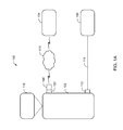
- FIG. 1A illustrates a first network environment for implementing an exemplary USB-to-Bluetooth (U2B) audio bridging device.
- U2B USB-to-Bluetooth
- FIG. 1B illustrates a second network environment for implementing the U2B audio bridging device.
- FIG. 1C illustrates a third network environment for implementing the U2B audio bridging device.
- FIG. 1D illustrates a fourth network environment for implementing the U2B audio bridging device.
- FIG. 2 illustrates the U2B audio bridging device.
- FIG. 3 illustrates an exemplary audio routing and mixing topology being implemented using the U2B audio bridging device.
- USB-to-Bluetooth (U2B) audio bridging device This disclosure describes a USB-to-Bluetooth (U2B) audio bridging device.
- U2B USB-to-Bluetooth
- the disclosed embodiments are intended to describe aspects of the disclosure in sufficient detail to enable those skilled in the art to practice the invention. Other embodiments may be utilized and changes may be made without departing from the scope of the disclosure. The following detailed description is not to be taken in a limiting sense, and the scope of the present invention is defined only by the included claims.
- the various illustrative functional units includes logical blocks, modules, and circuits described in connection with the embodiments disclosed herein so as to more particularly emphasize their implementation independence.
- the functional units may be implemented or performed with a general purpose processor, a special purpose processor, a Digital Signal Processor (DSP), an Application Specific Integrated Circuit (ASIC), a Field Programmable Gate Array (FPGA) or other programmable logic device, discrete gate or transistor logic, discrete hardware components, or any combination thereof designed to perform the functions described herein.
- a general purpose processor may be a microprocessor, any conventional processor, controller, microcontroller, or state machine.
- a general purpose processor may be considered a special purpose processor while the general purpose processor is configured to fetch and execute instructions (e.g., software code) stored on a computer readable medium such as any type of memory, storage, and/or storage devices.
- a processor may also be implemented as a combination of computing devices, such as a combination of a DSP and a microprocessor, a plurality of microprocessors, one or more microprocessors in conjunction with a DSP core, or any other such configuration.
- the various illustrative functional units previously described above may include software or programs such as computer readable instructions that may be described in terms of a process that may be depicted as a flowchart, a flow diagram, a structure diagram, or a block diagram.
- the process may describe operational acts as a sequential process, many of these acts can be performed in another sequence, in parallel, or substantially concurrently. Further, the order of the acts may be rearranged.
- the software may comprise one or more objects, agents, threads, lines of code, subroutines, separate software applications, two or more lines of code or other suitable software structures operating in one or more software applications or on one or more processors.
- the software may be distributed over several different code segments, among different programs, and across several memory devices.
- operational data may be identified and illustrated herein within modules, and may be embodied in any suitable form and organized within any suitable type of data structure. The operational data may be collected as a single data set, or may be distributed over different locations including over different storage devices.
- Elements described herein may include multiple instances of the same element. These elements may be generically indicated by a numerical designator (e.g. 110 ) and specifically indicated by the numerical indicator followed by an alphabetic designator (e.g., 110 A) or a numeric indicator preceded by a “dash” (e.g., 110 - 1 ).
- a numerical designator e.g. 110
- an alphabetic designator e.g., 110 A
- a numeric indicator preceded by a “dash” e.g., 110 - 1
- element number indicators begin with the number of the drawing on which the elements are introduced or most fully discussed. For example, where feasible elements in FIG. 3 are designated with a format of 3xx, where 3 indicates FIG. 3 and xx designates the unique element.
- any reference to an element herein using a designation such as “first,” “second,” and so forth does not limit the quantity or order of those elements, unless such limitation is explicitly stated. Rather, these designations may be used herein as a convenient method of distinguishing between two or more elements or instances of an element. Thus, a reference to first and second element does not mean that only two elements may be employed or that the first element must precede the second element in some manner.
- a set of elements may comprise one or more elements.
- the host device may refer to a networked computing device configured to at least one of (1) store, manage, or process audio, video, or alphanumeric data or documents, (2) establish a communication channel or environment, and (3) request services from or deliver services to, or both, other devices connected to the network.
- Various examples of the host device include, but not limited to, a desktop PC, a personal digital assistant (PDA), a server, a mainframe computer, a mobile computing device (for example, laptops, smartphone), etc.
- the host device may include one or more network interfaces typically found in networked computing devices that support one more network protocols.
- the endpoint may refer to one or more computing devices capable of establishing a communication channel for exchange of at least audio data in a communication session.
- Examples of the computing devices may include, but are not limited to, a desktop PC, a personal digital assistant (PDA), a server, a mainframe computer, a mobile computing device (for example, mobile phones, laptops, tablets, etc.), calling devices (for e.g., a telephone, a speakerphone, an internet phone, a video telephone, etc.).
- a “mobile communication device” is used in the present disclosure in the context of its broadest definition.
- the mobile communication device may refer to any of a variety of portable computing devices including a mobile phone, a tablet, a laptop, and so on, configured for or capable of providing audio signals.
- U2B audio bridging device is intended to cover any and/or all devices capable of performing respective operations on the endpoints in a conferencing environment relevant to the applicable context, regardless of whether or not the same are specifically provided.
- FIG. 1A illustrates a first network environment 100 for implementing an exemplary U2B audio bridging device according to an embodiment of the present disclosure.
- Embodiments are disclosed in the context of environments that represent an audio conference among multiple users via one or more endpoints such as audio conference endpoints (AC endpoints) capable of receiving audio signals either directly from users or from coupled audio sources, such as a mobile communication device and a unified communications (UC) application.
- AC endpoints audio conference endpoints
- UC unified communications
- the AC endpoint may execute a software application such as a UC application during a conference session.
- the first network environment 100 may include a host device 102 , a mobile communication device 104 (e.g., a mobile phone), and an AC endpoint 106 .
- the host device 102 may include one or more of a variety of interfaces known in the art, related art, or developed later including a PC Card slot, a Peripheral Component Interconnect (PCI), an Advanced Graphic Port (AGP) for being coupled to or communicate with one or more external devices.
- the host device 102 may include a first Universal Serial Bus (USB) port 107 and a second USB port 110 .
- USB Universal Serial Bus
- the first USB port 107 may be coupled to an adaptor 108 , which may be configured to communicate with the mobile communication device 104 over a network 112 based on a predetermined communication protocol.
- the adaptor 108 may be a Bluetooth adaptor configured to communicate with the mobile communication device 104 such as a mobile phone based on a Bluetooth communication protocol over the network 112 .
- the network 112 may include, for example, Wide Area Networks (WANs), Local Area Networks (LANs), Personal Area Networks (PANs), radio, television, and/or any other delivery or tunneling mechanism for carrying data such as audio data.
- the network 112 may comprise multiple networks or sub-networks, each of which may comprise, for example, a wireless data pathway.
- the network 112 may comprise a circuit-switched voice network, a packet-switched data network, or any other network that is able to carry electronic communications.
- the network 112 may comprise networks based on short range wireless communication protocols including, but not limited to, Bluetooth, ZigBee, Wi-Fi, ANT+, and Z-Wave.
- the network 112 may support voice using these protocols and other comparable protocols for voice data communications.
- the adaptor 108 may communicate with the mobile communication device 104 through a Bluetooth-type audio communication channel, or in other words, a short range wireless communication channel, being established based on a variety of corresponding Bluetooth-type communication standards known in the art, related art, or developed later including Bluetooth, Wi-Fi, ZigBee, and Z-Wave.
- the connection between the adaptor 108 and the mobile communication device 104 may be managed using a dedicated Bluetooth profile such as the hands free profile (HFP), the headset profile (HSP), or the advanced audio distribution profile (A2DP), which may be defined by the Bluetooth communication protocol for allowing encoding and transmission of audio data between the mobile communication device 104 and the adaptor 108 .
- HFP hands free profile
- HSP headset profile
- A2DP advanced audio distribution profile
- the mobile communication device 104 may pair or connect with the adaptor 108 in the headset profile for communicating audio data as an audio peripheral such as a headset.
- the mobile communication device 104 may be configured to receive audio data signals via the adaptor 108 .
- the host device 102 may be associated with various devices which may include, but are not limited to, a camera, display device, microphone, speakers, and one or more codecs, or any other type of conferencing hardware, or in any combination thereof through the interfaces such as the second USB port 110 .
- the host device 102 may comprise video, voice and data communication capabilities (for example, videoconferencing capabilities) by being coupled to or including, various audio devices (for example, microphones, audio input devices, speakers, audio output devices, telephones, speaker telephones, etc.), various video devices (for example, monitors, projectors, displays, televisions, video output devices, video input devices, cameras, etc.), various networks (IP, PSTN, etc.) or any combination thereof.
- the host device 102 may be configured to host and/or execute software applications.
- the software applications may include, but not limited to, unified communications (UC) applications such as Microsoft Lync, Skype, IBM SameTime, and Cisco IP Communicator.
- UC unified communications
- Each of the UC applications may operate with same or different communication protocols and media formats.
- the UC applications may generate audio data signals via a virtual audio device, e.g., a virtual sound card (not shown), being in communication with the host device 102 , discussed later in greater detail.
- the host device 102 may be coupled to the AC endpoint 106 via the second interface such as the second USB port 110 using a compatible transmission media such as a USB cable 114 .
- the AC endpoint 106 may be removably connected to the host device 102 as a peripheral device.
- the AC endpoint 106 may be configured to at least one of (1) receive audio data signals from one or more sources such as the host device 102 via the second USB port 110 , or directly from a user; (2) establish a communication channel with other locally or remotely located devices or endpoints such as AC endpoints over a network such as the Internet, analog or digital wired and wireless telephone networks (e.g., a PSTN, Integrated Services Digital Network (ISDN), a cellular network, and Digital Subscriber Line (xDSL)), satellite, and/or any other delivery or tunneling mechanism to send or receive audio data signals; and (3) store data from the received audio data signals.
- a PSTN Integrated Services Digital Network
- ISDN Integrated Services Digital Network
- xDSL Digital Subscriber Line
- the host device 102 may be installed, integrated, or operate in communication with a U2B audio bridging device 116 (hereinafter referred to as bridging device 116 ) configured to, at least one of: (1) create a logical representation of one or more networked devices such as the mobile communication device 104 in communication with the host device 102 ; (2) establish a local communication bridge or channel among the mobile communication device 104 , the AC endpoint 106 , and one or more software applications such as UC applications being executed by the host device 102 ; (3) store, manage, and process the audio data signals received from the AC endpoint 106 , the UC applications, and the mobile communication device 104 connected to the network 112 ; (4) request services from or deliver services to, or both, various devices connected to a network such as the network 112 ; and (5) combine audio data signals from two or more audio sources such as the mobile communication device 104 (via the adaptor 108 ), one or more UC applications (via a virtual audio device), and the peripheral device such as
- the audio bridging device 116 could be designed to appropriately mix the various audio data signals, using a mix-minus methodology, so that all conference participants can hear each other but not themselves.
- the bridging device 116 may facilitate integration of real-time and non-real-time communication services by establishing an audio bridge or communication channel among the mobile communication device 104 , the AC endpoint 106 , and one or more UC applications being simultaneously executed on the host device 102 .
- Examples of such real-time services may comprise, but are not limited to, instant voice messaging, audio conferencing, call control, and speech recognition.
- Examples of the non-real-time services may comprise, but are not limited to, voicemail and audio short messaging service (audio SMS).
- the bridging device 116 may be implemented as a standalone and dedicated device including hardware and installed software, where the hardware is closely matched to the requirements and/or functionality of the software.
- the bridging device 116 may be implemented as a software application or a device driver. The bridging device 116 may enhance or increase the functionality and/or capacity of the network 112 to which it is connected.
- the bridging device 116 may be configured to expose its computing environment or operating code to the user, and may comprise related art I/O devices, such as a microphone, a speaker, a scanner, a keyboard, or a display.
- the bridging device 116 may, however, comprise software, firmware or other resources that support remote administration and/or maintenance of the bridging device 116 .
- the bridging device 116 may comprise at least one processor (not shown) executing machine readable program instructions for performing various operations, such as those discussed above, on the received audio data signals.
- the bridging device 116 may comprise, in whole or in part, a software application such as a conference application (discussed below in greater detail) working alone or in conjunction with one or more hardware resources such as the host device 102 .
- Such software applications may be executed by the processor on different hardware platforms or emulated in a virtual environment. Aspects of the bridging device 116 may leverage known, related art, or later developed off-the-shelf software.
- embodiments of the second network environment 130 may include the bridging device 116 being integrated with, or installed on, a network appliance 132 that is associated with or used to establish the network 112 .
- the network appliance 132 may be capable of operating as an interface device to assist exchange of program instructions and audio data between the bridging device 116 and the mobile communication device 104 via the adaptor 108 .
- the network appliance 132 may be preconfigured or dynamically configured to include the bridging device 116 integrated with other devices.
- the bridging device 116 may be integrated with the AC endpoint 106 , as shown in a third network environment 150 of FIG.
- the bridging device 116 may include a module (not shown), which may introduce the bridging device 116 to the network appliance 132 , thereby enabling the network appliance 132 to invoke the bridging device 116 as a service.
- Examples of the network appliance 132 may comprise, but are not limited to, a DSL modem, a wireless access point, a router, and a gateway having a predetermined computing power sufficient for implementing the bridging device 116 .
- FIG. 2 illustrates the U2B audio bridging device of FIG. 1A according to an embodiment of the present disclosure.
- the bridging device 116 may be implemented in a single device, as illustrated, or may be distributed across multiple devices.
- the bridging device 116 may be implemented in hardware or a suitable combination of hardware and software, and may comprise one or more software systems operating on a digital signal processing platform.
- the “hardware” may comprise a combination of discrete components, an integrated circuit, an application-specific integrated circuit, a field programmable gate array, a digital signal processor, or other suitable hardware.
- the “software” may comprise one or more objects, agents, threads, lines of code, subroutines, separate software applications, two or more lines of code or other suitable software structures operating in one or more software applications or on one or more processor(s) 202 .
- the processor(s) 202 may include, for example, microprocessors, microcomputers, microcontrollers, digital signal processors, central processing units, state machines, logic circuits, and/or any devices that manipulate signals based on operational instructions.
- the processor(s) 202 may be configured to fetch and execute computer readable instructions in a memory such as a system memory 204 associated with the bridging device 116 for performing tasks such as signal transcoding, input/output data processing, power control, and/or other functions.
- Embodiments may include the bridging device 116 operating as or in an Internet access node, application server, IMS core, service node, or some other communication device or system, including any combination thereof.
- the bridging device 116 may comprise or implement one or more real time protocols, for e.g., session initiation protocol (SIP), H.261, H.263, H.264, H.323, among others.
- SIP session initiation protocol
- the bridging device 116 may be integrated with or implemented as a set of instructions in a portable storage device; a wearable device such as a fashion accessory (e.g., a wrist band, a ring, etc.) and a body clothing; a utility device (a hand-held baton, a pen, an umbrella, a watch, etc.); or any combination thereof.
- a wearable device such as a fashion accessory (e.g., a wrist band, a ring, etc.) and a body clothing
- a utility device a hand-held baton, a pen, an umbrella, a watch, etc.
- the bridging device 116 may include a variety of known, related art, or later developed interface(s) 206 , including software interfaces (e.g., an application programming interface, a graphical user interface, etc.); hardware interfaces (e.g., cable connectors, the keyboard, an interactive display screen, etc.); or both.
- the bridging device 116 may be in communication or integrated with the adaptor 108 interfacing with the mobile communication device 104 .
- the bridging device 116 may further include the system memory 204 for storing at least one of (1) audio or video data, associated metadata (e.g., data size, data format, creation date, communication protocol through which the audio data signal may be communicated, associated tags or labels, related messages, etc.), and related files; (2) an interface device type, (3) a log of profiles of network devices and associated communications including instructions, queries, conversations, data, and related metadata; and (4) logical representations of the network devices.
- associated metadata e.g., data size, data format, creation date, communication protocol through which the audio data signal may be communicated, associated tags or labels, related messages, etc.
- the system memory 204 may comprise of any computer-readable medium known in the art, related art, or developed later including, for example, a processor or multiple processors operatively connected together, volatile memory (e.g., RAM), non-volatile memory (e.g., flash, etc.), disk drive, etc., or any combination thereof.
- volatile memory e.g., RAM
- non-volatile memory e.g., flash, etc.
- the system memory 204 may include one or more databases such as a database 208 , which may be sub-divided into further databases for storing electronic files and data such as audio or video data.
- the system memory 204 may have one of many database schemas known in the art, related art, or developed later for storing data from the host device 102 , the mobile communication device 104 , or the AC endpoint 106 via the bridging device 116 .
- the database 208 may have a relational database schema involving a primary key attribute and one or more secondary attributes.
- the bridging device 116 may perform one or more operations, but not limited to, reading, writing, indexing, labeling, updating, and modifying the data, and may communicate with various networked devices.
- the system memory 204 may include various modules such as an input module 210 , a multipoint control unit (MCU) 212 , and an output module 214 .
- the input module 210 may be configured to receive audio data signals in various real-time or non-real time communication protocols.
- the input module 210 may receive a first set of audio data signals as Bluetooth signals (hereinafter referred to as BT signals) via the adaptor 108 from the mobile communication device 104 over the network 112 ; a second set of audio data signals (hereinafter referred to as USB signals) via the USB port 110 from the AC endpoint 106 ; and a third set of audio data signals (hereinafter referred to as UC signals) from a UC application being executed by the host device 102 via the virtual audio device, e.g., a virtual sound card. Any of these received audio data signals may be encoded using a variety of encoding algorithms known in the art, related art, or developed later.
- the input module 210 may decode these encoded BT signals, the USB signals, and the UC signals and send them to the MCU 212 for further processing.
- the input module 210 may convert the BT signals, the USB signals, and the UC signals into corresponding data packets, namely, BT packets, USB packets, and UC packets in accordance with, for example, the TCP/IP Specification and H.323 Specification.
- the MCU 212 may receive the BT signals, the USB signals, and the UC signals from the input module 210 .
- the MCU 212 may be configured to implement various real-time and non-real time communication protocols for rendering and/or transmitting the BT signals, the USB signals, and the UC signals received from the input module 210 .
- the MCU 212 may be further configured to determine various characteristics of the connected physical or virtual devices such as the AC endpoint 106 , the mobile communication device 104 , and the virtual audio device for handling the respective received signals. The characteristics may include, but are not limited to, type (for example, a mobile phone, a speakerphone, etc.) of the connected device, supported audio bit rate, supported codecs, network connection speed, and so on.
- the MCU 212 may be configured to map the second USB port 110 to the adaptor 108 , via the first USB port 107 , e.g., upon determining the attached devices being active, to create an audio bridge or communication channel between the second USB port 110 and the adaptor 108 for audio data communication.
- the MCU 212 may map the second USB port 110 to the adaptor 108 upon determining that the mobile communication device 104 is paired with the adaptor 108 over the network 112 and the AC endpoint 106 being physically connected to the second USB port 110 .
- the MCU 212 may map the second USB port 110 to the virtual audio device in a similar manner upon determining the second USB port 110 and the virtual audio device being active to create an audio bridge for audio data communication.
- the MCU 212 may be configured to combine audio data signals from multiple devices such as at least two of the mobile communication device 104 , the AC endpoint 106 , and the UC application to create a composite audio data signal for transmission to at least one of the remaining coupled devices.
- the MCU 212 may combine the BT signals and the UC signals to create a composite audio data signal for transmission to the AC endpoint 106 via the second USB port 110 , discussed below in greater detail.
- the MCU 212 may transmit the received audio data signals, and/or at least one composite audio data signal, in some embodiments, to the output module 214 for being transmitted to the mapped destinations over the created local audio bridge using the bridging device 116 .
- the output module 214 may be configured to convert the audio data signals received from the MCU 212 into an appropriate format that may be compatible with one or more mapped destinations. For example, the output module 214 may convert the USB signals into Bluetooth compatible signals for being communicated to the mobile communication device 104 via the adaptor 108 , and vice versa. Similarly, the output module 214 may convert the USB signals into an appropriate format for being played by the virtual audio device in communication with the UC application executed by the host device 102 , and vice versa. In some embodiments, the output module 214 may store audio data corresponding to the BT signals, the USB signals, or the UC signal into the database 208 .
- FIG. 3 illustrates an exemplary audio mixing topology being implemented using the U2B audio bridging device of FIG. 1A according to an embodiment of the present disclosure.
- the audio mixing topology 300 may include a software application configured to operate as a conference application 302 being executed on the host device 102 or the bridging device 116 to control or manage the bridging device 116 .
- the conference application 302 may dynamically control various attributes of the bridging device 116 including activation and deactivation of the bridging device 116 .
- attributes may include, but not limited to, on-the-fly mapping of two or more interface devices such as the adaptor 108 and the second USB port 110 to each other, dynamic selection of communication protocols and output formats of the audio data signals for transmission, and customized selection of input audio sources and compatible destination devices.
- the conference application 302 may communicate with the adaptor 108 , the AC endpoint 106 , and the virtual audio device via a UC application such as a UC application 304 being executed by the host device 102 for mapping the second USB port 110 , which is in communication with the AC endpoint 106 , to the adaptor 108 and the virtual audio device for communication of audio data signals from these devices.
- a UC application such as a UC application 304 being executed by the host device 102 for mapping the second USB port 110 , which is in communication with the AC endpoint 106 , to the adaptor 108 and the virtual audio device for communication of audio data signals from these devices.
- the conference application 302 may be preconfigured or dynamically configured, e.g., by a user, to operate the bridging device 116 for combining the UC signals, UCin 306 , received as input from the UC application 304 and the BT signals, BTin 308 , received as input from the adaptor 108 to generate a composite audio data output signal such as an AC output signal, ACout 310 , which may be communicated to the AC endpoint 106 via the USB port 110 by the bridging device 116 as shown in Equation 1.
- AC out ⁇ ( UC in+ BT in) (1)
- the conference application 302 may be preconfigured or dynamically configured, e.g., by a user, to operate the bridging device 116 for combining the UC signals, UCin 306 , received as input from the UC application 304 and the USB signals, USBin 312 , received as input from the AC endpoint 106 via the second USB port 110 to generate a composite audio data output signal such as a BT output signal, BTout 314 , which may be communicated to the mobile communication device 104 via the adaptor 108 by the bridging device 116 as shown in Equation 2.
- BT out ⁇ ( UC in+ AC in) (2)
- the conference application 302 may be preconfigured or dynamically configured, e.g., by a user, to operate the bridging device 116 for combining the BT signals, BTin 308 , received as input from the mobile communication device 104 via the adaptor 108 and the USB signals, USBin 312 , received as input from the AC endpoint 106 via the second USB port 110 to generate a composite audio data output signal such as a UC output signal, UCout 316 , which may be communicated to the virtual audio device via the UC application 304 by the bridging device 116 as shown in Equation 3.
- UC out ⁇ ( USB in+ AC in) (3)
- the conference application 302 or client may be configured to route and mix two or more received input audio signals to the mapped destinations using the bridging device 116 .
- this disclosure describes a USB-to-Bluetooth audio bridging device.
- the present disclosure enables local connection between the terminal equipment and the AC endpoint while the AC endpoint is independent of the wireless communication technology implemented on the terminal equipment.
- One embodiment of the present disclosure provides a system comprising a host device 102 , an adaptor 108 , a peripheral device, a mobile communication device 104 , and an audio bridging device 116 .
- the host device 102 includes a first universal serial bus (USB) interface and a second USB interface, wherein said host device 102 is configured to execute a first software application generating a first audio data signal via a virtual audio device.
- the adaptor 108 is coupled to said first USB interface, wherein said adaptor 108 is compatible to operate based on a Bluetooth-type communication protocol.
- the peripheral device is coupled to said second USB interface.
- the mobile communication device 104 is linked to said host device 102 via said adaptor 108 , wherein said mobile communication device 104 is configured to communicate a second audio data signal to said adaptor 108 over a wireless network.
- the audio bridging device 116 is in communication with said host device 102 , wherein said audio bridging device 116 is configured to map said second USB interface to at least one of said adaptor 108 and said virtual audio device, wherein said audio bridging device 116 is configured to route at least one of said first audio data signal, said second audio data signal, and a combination thereof to said peripheral device via said second USB interface.
Landscapes
- Engineering & Computer Science (AREA)
- Theoretical Computer Science (AREA)
- Physics & Mathematics (AREA)
- General Engineering & Computer Science (AREA)
- General Physics & Mathematics (AREA)
- Health & Medical Sciences (AREA)
- Multimedia (AREA)
- Audiology, Speech & Language Pathology (AREA)
- General Health & Medical Sciences (AREA)
- Human Computer Interaction (AREA)
- Signal Processing (AREA)
- Acoustics & Sound (AREA)
- Telephone Function (AREA)
- Computer Networks & Wireless Communication (AREA)
Abstract
Description
ACout=Σ(UCin+BTin) (1)
BTout=Σ(UCin+ACin) (2)
UCout=Σ(USBin+ACin) (3)
Claims (20)
Priority Applications (1)
| Application Number | Priority Date | Filing Date | Title |
|---|---|---|---|
| US14/561,700 US9921798B2 (en) | 2013-12-05 | 2014-12-05 | Universal Serial Bus-to-Bluetooth audio bridging devices |
Applications Claiming Priority (2)
| Application Number | Priority Date | Filing Date | Title |
|---|---|---|---|
| US201361912063P | 2013-12-05 | 2013-12-05 | |
| US14/561,700 US9921798B2 (en) | 2013-12-05 | 2014-12-05 | Universal Serial Bus-to-Bluetooth audio bridging devices |
Publications (2)
| Publication Number | Publication Date |
|---|---|
| US20150199169A1 US20150199169A1 (en) | 2015-07-16 |
| US9921798B2 true US9921798B2 (en) | 2018-03-20 |
Family
ID=53521425
Family Applications (1)
| Application Number | Title | Priority Date | Filing Date |
|---|---|---|---|
| US14/561,700 Active 2035-08-23 US9921798B2 (en) | 2013-12-05 | 2014-12-05 | Universal Serial Bus-to-Bluetooth audio bridging devices |
Country Status (1)
| Country | Link |
|---|---|
| US (1) | US9921798B2 (en) |
Families Citing this family (6)
| Publication number | Priority date | Publication date | Assignee | Title |
|---|---|---|---|---|
| CN105323534B (en) * | 2014-07-14 | 2019-04-23 | 深圳市潮流网络技术有限公司 | A kind of the meeting processing method and communication apparatus of third-party application |
| JP2017072887A (en) * | 2015-10-05 | 2017-04-13 | 株式会社東芝 | Information processing system |
| CN107800993B (en) * | 2016-09-06 | 2021-05-14 | 中兴通讯股份有限公司 | Connecting method, device and system for multimedia conference |
| EP3683637B1 (en) * | 2019-01-16 | 2023-03-22 | Siemens Aktiengesellschaft | Method for producing a bidirectional connection between a device, in particular a field device, and an application in a central device |
| US12028671B2 (en) * | 2021-09-29 | 2024-07-02 | Hewlett-Packard Development Company, L.P. | Passive analog bypass for USB peripheral audio devices |
| CN116193222A (en) * | 2021-11-26 | 2023-05-30 | 北京三快在线科技有限公司 | UAV Camera System and UAV |
Citations (14)
| Publication number | Priority date | Publication date | Assignee | Title |
|---|---|---|---|---|
| US20030021423A1 (en) * | 2001-05-03 | 2003-01-30 | Harman International Industries Incorporated | System for transitioning from stereo to simulated surround sound |
| US20050037807A1 (en) | 2003-06-26 | 2005-02-17 | Michael Dove | Interface device coupled to PC host via USB |
| US20060103721A1 (en) | 2004-11-12 | 2006-05-18 | Chien-Chung Shih | Video conference system utilizing a mobile phone and method thereof |
| US20060193301A1 (en) * | 2005-02-28 | 2006-08-31 | Ascalade Communications Inc. | Graphic display cordless telephone interfacing with soft-phone UI |
| US20090100178A1 (en) * | 2007-10-15 | 2009-04-16 | Gonzales Cesar A | Systems and Methods for Access and Control of Hardware Device Resources Using Device-Independent Access Interfaces |
| US8121547B2 (en) | 2008-12-24 | 2012-02-21 | Plantronics, Inc. | In-headset conference calling |
| US20120172004A1 (en) * | 2010-07-19 | 2012-07-05 | Christopher Anthony Silva | Method and system for wireless phone recording |
| US20120188999A1 (en) | 2011-01-21 | 2012-07-26 | Dell Products, Lp | Personal Computer and Mobile Phone Communications through Peer-to-Peer Connection |
| US8233930B1 (en) * | 2007-01-16 | 2012-07-31 | Sprint Spectrum L.P. | Dual-channel conferencing with connection-based floor control |
| US8326338B1 (en) | 2011-03-29 | 2012-12-04 | OnAir3G Holdings Ltd. | Synthetic radio channel utilizing mobile telephone networks and VOIP |
| US8363844B2 (en) | 2008-12-24 | 2013-01-29 | Plantronics, Inc. | Contextual audio switching for a USB controlled audio device |
| US20130097244A1 (en) * | 2011-09-30 | 2013-04-18 | Clearone Communications, Inc. | Unified communications bridging architecture |
| US20130183901A1 (en) * | 2012-01-16 | 2013-07-18 | Gn Netcom A/S | Call Management Through A Hands Free Communication Device |
| US20140122588A1 (en) * | 2012-10-31 | 2014-05-01 | Alain Nimri | Automatic Notification of Audience Boredom during Meetings and Conferences |
-
2014
- 2014-12-05 US US14/561,700 patent/US9921798B2/en active Active
Patent Citations (14)
| Publication number | Priority date | Publication date | Assignee | Title |
|---|---|---|---|---|
| US20030021423A1 (en) * | 2001-05-03 | 2003-01-30 | Harman International Industries Incorporated | System for transitioning from stereo to simulated surround sound |
| US20050037807A1 (en) | 2003-06-26 | 2005-02-17 | Michael Dove | Interface device coupled to PC host via USB |
| US20060103721A1 (en) | 2004-11-12 | 2006-05-18 | Chien-Chung Shih | Video conference system utilizing a mobile phone and method thereof |
| US20060193301A1 (en) * | 2005-02-28 | 2006-08-31 | Ascalade Communications Inc. | Graphic display cordless telephone interfacing with soft-phone UI |
| US8233930B1 (en) * | 2007-01-16 | 2012-07-31 | Sprint Spectrum L.P. | Dual-channel conferencing with connection-based floor control |
| US20090100178A1 (en) * | 2007-10-15 | 2009-04-16 | Gonzales Cesar A | Systems and Methods for Access and Control of Hardware Device Resources Using Device-Independent Access Interfaces |
| US8121547B2 (en) | 2008-12-24 | 2012-02-21 | Plantronics, Inc. | In-headset conference calling |
| US8363844B2 (en) | 2008-12-24 | 2013-01-29 | Plantronics, Inc. | Contextual audio switching for a USB controlled audio device |
| US20120172004A1 (en) * | 2010-07-19 | 2012-07-05 | Christopher Anthony Silva | Method and system for wireless phone recording |
| US20120188999A1 (en) | 2011-01-21 | 2012-07-26 | Dell Products, Lp | Personal Computer and Mobile Phone Communications through Peer-to-Peer Connection |
| US8326338B1 (en) | 2011-03-29 | 2012-12-04 | OnAir3G Holdings Ltd. | Synthetic radio channel utilizing mobile telephone networks and VOIP |
| US20130097244A1 (en) * | 2011-09-30 | 2013-04-18 | Clearone Communications, Inc. | Unified communications bridging architecture |
| US20130183901A1 (en) * | 2012-01-16 | 2013-07-18 | Gn Netcom A/S | Call Management Through A Hands Free Communication Device |
| US20140122588A1 (en) * | 2012-10-31 | 2014-05-01 | Alain Nimri | Automatic Notification of Audience Boredom during Meetings and Conferences |
Non-Patent Citations (4)
| Title |
|---|
| Clearone®, "Audio and Video Solutions Guide: Great Ideas Need to be Heard", 2011, 112 pages. |
| Konftel, "The Konftel 55W User Guide", Available at <http://www.konftel.com/Global/PDF/User_guide/Konftel_55W/Konftel55W-UG_ENG.pdf>, Retreived on Oct. 18, 2013, 41 pages. |
| Ploycom Inc, "Ploycom® : User Guide", VoiceStation™ 500, 2005, 24 pages. |
| Tom's Hardware, "Audio Conferencing Using Bluetooth Enabled Mobile", Document Available at <http://www.tomshardware.com/forum/50952-36-audio-conferencing-bluetooth-enabled-mobile> Retreived on Oct. 18, 2013, 3 pages. |
Also Published As
| Publication number | Publication date |
|---|---|
| US20150199169A1 (en) | 2015-07-16 |
Similar Documents
| Publication | Publication Date | Title |
|---|---|---|
| US9921798B2 (en) | Universal Serial Bus-to-Bluetooth audio bridging devices | |
| US9781386B2 (en) | Virtual multipoint control unit for unified communications | |
| US11805158B2 (en) | Method and system for elevating a phone call into a video conferencing session | |
| US9935915B2 (en) | System and method that bridges communications between multiple unfied communication(UC) clients | |
| US20150288735A1 (en) | Virtual Audio Device System for Unified Communications Applications | |
| JP7448672B2 (en) | Information processing methods, systems, devices, electronic devices and storage media | |
| US20140148934A1 (en) | Unified communications bridging architecture | |
| US20100040217A1 (en) | System and method for identifying an active participant in a multiple user communication session | |
| CN104365088A (en) | Multiple channel communication using multiple cameras | |
| KR102095533B1 (en) | Electronic device and method for providing notification information selectively | |
| CN105025164A (en) | Communication information management system and method | |
| CN103870434B (en) | Integrated audio and video conference capabilities | |
| CN106209818A (en) | A kind of wireless interactive electronic whiteboard conference system | |
| US20180063481A1 (en) | Human interface device (hid) based control of video data conversion at docking station | |
| CN108108139A (en) | A kind of throwing screen cut-in method of cloud meeting | |
| TW202042102A (en) | Online translation method, system and equipment based on teleconference and storage medium | |
| WO2018032903A1 (en) | Provision protocol transmission-based terminal configuration method and terminal | |
| US10149090B2 (en) | Mobile cast receivers for computing and entertainment devices | |
| US20210203883A1 (en) | Video conference terminal and video conference system | |
| JP2014149644A (en) | Electronic meeting system | |
| US9678579B2 (en) | Mobile cast receivers for computing and entertainment devices | |
| CN112104649A (en) | Multimedia interaction method and device, electronic equipment, server and storage medium | |
| US20140295806A1 (en) | Encoded identifier based network | |
| CN104077143A (en) | System and method for showing slides | |
| CN111263100A (en) | Video call method, device, equipment and storage medium |
Legal Events
| Date | Code | Title | Description |
|---|---|---|---|
| AS | Assignment |
Owner name: CLEARONE INC., UTAH Free format text: ASSIGNMENT OF ASSIGNORS INTEREST;ASSIGNORS:MANLEY, PETER H.;KRISHNAMOORTHY, BALASUBRAMANIYAN;GRAHAM, DEREK;SIGNING DATES FROM 20150203 TO 20150204;REEL/FRAME:034900/0365 |
|
| STCF | Information on status: patent grant |
Free format text: PATENTED CASE |
|
| CC | Certificate of correction | ||
| MAFP | Maintenance fee payment |
Free format text: PAYMENT OF MAINTENANCE FEE, 4TH YR, SMALL ENTITY (ORIGINAL EVENT CODE: M2551); ENTITY STATUS OF PATENT OWNER: SMALL ENTITY Year of fee payment: 4 |
|
| FEPP | Fee payment procedure |
Free format text: ENTITY STATUS SET TO UNDISCOUNTED (ORIGINAL EVENT CODE: BIG.); ENTITY STATUS OF PATENT OWNER: LARGE ENTITY |
|
| MAFP | Maintenance fee payment |
Free format text: PAYMENT OF MAINTENANCE FEE, 8TH YEAR, LARGE ENTITY (ORIGINAL EVENT CODE: M1552); ENTITY STATUS OF PATENT OWNER: LARGE ENTITY Year of fee payment: 8 |
|
| AS | Assignment |
Owner name: BIAMP SYSTEMS, LLC, OREGON Free format text: ASSIGNMENT OF ASSIGNORS INTEREST;ASSIGNOR:CLEARONE HOLDING, LLC;REEL/FRAME:072737/0439 Effective date: 20251024 |