US9920414B2 - Method for producing a ceramic layer on a surface formed from an Ni base alloy - Google Patents
Method for producing a ceramic layer on a surface formed from an Ni base alloy Download PDFInfo
- Publication number
- US9920414B2 US9920414B2 US14/372,391 US201314372391A US9920414B2 US 9920414 B2 US9920414 B2 US 9920414B2 US 201314372391 A US201314372391 A US 201314372391A US 9920414 B2 US9920414 B2 US 9920414B2
- Authority
- US
- United States
- Prior art keywords
- ceramic layer
- gas phase
- gas
- base alloy
- components
- Prior art date
- Legal status (The legal status is an assumption and is not a legal conclusion. Google has not performed a legal analysis and makes no representation as to the accuracy of the status listed.)
- Expired - Fee Related, expires
Links
Images


Classifications
-
- C—CHEMISTRY; METALLURGY
- C23—COATING METALLIC MATERIAL; COATING MATERIAL WITH METALLIC MATERIAL; CHEMICAL SURFACE TREATMENT; DIFFUSION TREATMENT OF METALLIC MATERIAL; COATING BY VACUUM EVAPORATION, BY SPUTTERING, BY ION IMPLANTATION OR BY CHEMICAL VAPOUR DEPOSITION, IN GENERAL; INHIBITING CORROSION OF METALLIC MATERIAL OR INCRUSTATION IN GENERAL
- C23C—COATING METALLIC MATERIAL; COATING MATERIAL WITH METALLIC MATERIAL; SURFACE TREATMENT OF METALLIC MATERIAL BY DIFFUSION INTO THE SURFACE, BY CHEMICAL CONVERSION OR SUBSTITUTION; COATING BY VACUUM EVAPORATION, BY SPUTTERING, BY ION IMPLANTATION OR BY CHEMICAL VAPOUR DEPOSITION, IN GENERAL
- C23C4/00—Coating by spraying the coating material in the molten state, e.g. by flame, plasma or electric discharge
- C23C4/18—After-treatment
-
- C—CHEMISTRY; METALLURGY
- C23—COATING METALLIC MATERIAL; COATING MATERIAL WITH METALLIC MATERIAL; CHEMICAL SURFACE TREATMENT; DIFFUSION TREATMENT OF METALLIC MATERIAL; COATING BY VACUUM EVAPORATION, BY SPUTTERING, BY ION IMPLANTATION OR BY CHEMICAL VAPOUR DEPOSITION, IN GENERAL; INHIBITING CORROSION OF METALLIC MATERIAL OR INCRUSTATION IN GENERAL
- C23C—COATING METALLIC MATERIAL; COATING MATERIAL WITH METALLIC MATERIAL; SURFACE TREATMENT OF METALLIC MATERIAL BY DIFFUSION INTO THE SURFACE, BY CHEMICAL CONVERSION OR SUBSTITUTION; COATING BY VACUUM EVAPORATION, BY SPUTTERING, BY ION IMPLANTATION OR BY CHEMICAL VAPOUR DEPOSITION, IN GENERAL
- C23C14/00—Coating by vacuum evaporation, by sputtering or by ion implantation of the coating forming material
- C23C14/06—Coating by vacuum evaporation, by sputtering or by ion implantation of the coating forming material characterised by the coating material
- C23C14/08—Oxides
- C23C14/081—Oxides of aluminium, magnesium or beryllium
-
- C—CHEMISTRY; METALLURGY
- C23—COATING METALLIC MATERIAL; COATING MATERIAL WITH METALLIC MATERIAL; CHEMICAL SURFACE TREATMENT; DIFFUSION TREATMENT OF METALLIC MATERIAL; COATING BY VACUUM EVAPORATION, BY SPUTTERING, BY ION IMPLANTATION OR BY CHEMICAL VAPOUR DEPOSITION, IN GENERAL; INHIBITING CORROSION OF METALLIC MATERIAL OR INCRUSTATION IN GENERAL
- C23C—COATING METALLIC MATERIAL; COATING MATERIAL WITH METALLIC MATERIAL; SURFACE TREATMENT OF METALLIC MATERIAL BY DIFFUSION INTO THE SURFACE, BY CHEMICAL CONVERSION OR SUBSTITUTION; COATING BY VACUUM EVAPORATION, BY SPUTTERING, BY ION IMPLANTATION OR BY CHEMICAL VAPOUR DEPOSITION, IN GENERAL
- C23C14/00—Coating by vacuum evaporation, by sputtering or by ion implantation of the coating forming material
- C23C14/06—Coating by vacuum evaporation, by sputtering or by ion implantation of the coating forming material characterised by the coating material
- C23C14/08—Oxides
- C23C14/083—Oxides of refractory metals or yttrium
-
- C—CHEMISTRY; METALLURGY
- C23—COATING METALLIC MATERIAL; COATING MATERIAL WITH METALLIC MATERIAL; CHEMICAL SURFACE TREATMENT; DIFFUSION TREATMENT OF METALLIC MATERIAL; COATING BY VACUUM EVAPORATION, BY SPUTTERING, BY ION IMPLANTATION OR BY CHEMICAL VAPOUR DEPOSITION, IN GENERAL; INHIBITING CORROSION OF METALLIC MATERIAL OR INCRUSTATION IN GENERAL
- C23C—COATING METALLIC MATERIAL; COATING MATERIAL WITH METALLIC MATERIAL; SURFACE TREATMENT OF METALLIC MATERIAL BY DIFFUSION INTO THE SURFACE, BY CHEMICAL CONVERSION OR SUBSTITUTION; COATING BY VACUUM EVAPORATION, BY SPUTTERING, BY ION IMPLANTATION OR BY CHEMICAL VAPOUR DEPOSITION, IN GENERAL
- C23C14/00—Coating by vacuum evaporation, by sputtering or by ion implantation of the coating forming material
- C23C14/22—Coating by vacuum evaporation, by sputtering or by ion implantation of the coating forming material characterised by the process of coating
- C23C14/24—Vacuum evaporation
-
- C—CHEMISTRY; METALLURGY
- C23—COATING METALLIC MATERIAL; COATING MATERIAL WITH METALLIC MATERIAL; CHEMICAL SURFACE TREATMENT; DIFFUSION TREATMENT OF METALLIC MATERIAL; COATING BY VACUUM EVAPORATION, BY SPUTTERING, BY ION IMPLANTATION OR BY CHEMICAL VAPOUR DEPOSITION, IN GENERAL; INHIBITING CORROSION OF METALLIC MATERIAL OR INCRUSTATION IN GENERAL
- C23C—COATING METALLIC MATERIAL; COATING MATERIAL WITH METALLIC MATERIAL; SURFACE TREATMENT OF METALLIC MATERIAL BY DIFFUSION INTO THE SURFACE, BY CHEMICAL CONVERSION OR SUBSTITUTION; COATING BY VACUUM EVAPORATION, BY SPUTTERING, BY ION IMPLANTATION OR BY CHEMICAL VAPOUR DEPOSITION, IN GENERAL
- C23C14/00—Coating by vacuum evaporation, by sputtering or by ion implantation of the coating forming material
- C23C14/58—After-treatment
- C23C14/5846—Reactive treatment
- C23C14/5853—Oxidation
-
- C—CHEMISTRY; METALLURGY
- C23—COATING METALLIC MATERIAL; COATING MATERIAL WITH METALLIC MATERIAL; CHEMICAL SURFACE TREATMENT; DIFFUSION TREATMENT OF METALLIC MATERIAL; COATING BY VACUUM EVAPORATION, BY SPUTTERING, BY ION IMPLANTATION OR BY CHEMICAL VAPOUR DEPOSITION, IN GENERAL; INHIBITING CORROSION OF METALLIC MATERIAL OR INCRUSTATION IN GENERAL
- C23C—COATING METALLIC MATERIAL; COATING MATERIAL WITH METALLIC MATERIAL; SURFACE TREATMENT OF METALLIC MATERIAL BY DIFFUSION INTO THE SURFACE, BY CHEMICAL CONVERSION OR SUBSTITUTION; COATING BY VACUUM EVAPORATION, BY SPUTTERING, BY ION IMPLANTATION OR BY CHEMICAL VAPOUR DEPOSITION, IN GENERAL
- C23C16/00—Chemical coating by decomposition of gaseous compounds, without leaving reaction products of surface material in the coating, i.e. chemical vapour deposition [CVD] processes
- C23C16/02—Pretreatment of the material to be coated
- C23C16/0272—Deposition of sub-layers, e.g. to promote the adhesion of the main coating
-
- C—CHEMISTRY; METALLURGY
- C23—COATING METALLIC MATERIAL; COATING MATERIAL WITH METALLIC MATERIAL; CHEMICAL SURFACE TREATMENT; DIFFUSION TREATMENT OF METALLIC MATERIAL; COATING BY VACUUM EVAPORATION, BY SPUTTERING, BY ION IMPLANTATION OR BY CHEMICAL VAPOUR DEPOSITION, IN GENERAL; INHIBITING CORROSION OF METALLIC MATERIAL OR INCRUSTATION IN GENERAL
- C23C—COATING METALLIC MATERIAL; COATING MATERIAL WITH METALLIC MATERIAL; SURFACE TREATMENT OF METALLIC MATERIAL BY DIFFUSION INTO THE SURFACE, BY CHEMICAL CONVERSION OR SUBSTITUTION; COATING BY VACUUM EVAPORATION, BY SPUTTERING, BY ION IMPLANTATION OR BY CHEMICAL VAPOUR DEPOSITION, IN GENERAL
- C23C16/00—Chemical coating by decomposition of gaseous compounds, without leaving reaction products of surface material in the coating, i.e. chemical vapour deposition [CVD] processes
- C23C16/22—Chemical coating by decomposition of gaseous compounds, without leaving reaction products of surface material in the coating, i.e. chemical vapour deposition [CVD] processes characterised by the deposition of inorganic material, other than metallic material
- C23C16/30—Deposition of compounds, mixtures or solid solutions, e.g. borides, carbides, nitrides
- C23C16/40—Oxides
- C23C16/405—Oxides of refractory metals or yttrium
-
- C—CHEMISTRY; METALLURGY
- C23—COATING METALLIC MATERIAL; COATING MATERIAL WITH METALLIC MATERIAL; CHEMICAL SURFACE TREATMENT; DIFFUSION TREATMENT OF METALLIC MATERIAL; COATING BY VACUUM EVAPORATION, BY SPUTTERING, BY ION IMPLANTATION OR BY CHEMICAL VAPOUR DEPOSITION, IN GENERAL; INHIBITING CORROSION OF METALLIC MATERIAL OR INCRUSTATION IN GENERAL
- C23C—COATING METALLIC MATERIAL; COATING MATERIAL WITH METALLIC MATERIAL; SURFACE TREATMENT OF METALLIC MATERIAL BY DIFFUSION INTO THE SURFACE, BY CHEMICAL CONVERSION OR SUBSTITUTION; COATING BY VACUUM EVAPORATION, BY SPUTTERING, BY ION IMPLANTATION OR BY CHEMICAL VAPOUR DEPOSITION, IN GENERAL
- C23C16/00—Chemical coating by decomposition of gaseous compounds, without leaving reaction products of surface material in the coating, i.e. chemical vapour deposition [CVD] processes
- C23C16/56—After-treatment
-
- C—CHEMISTRY; METALLURGY
- C23—COATING METALLIC MATERIAL; COATING MATERIAL WITH METALLIC MATERIAL; CHEMICAL SURFACE TREATMENT; DIFFUSION TREATMENT OF METALLIC MATERIAL; COATING BY VACUUM EVAPORATION, BY SPUTTERING, BY ION IMPLANTATION OR BY CHEMICAL VAPOUR DEPOSITION, IN GENERAL; INHIBITING CORROSION OF METALLIC MATERIAL OR INCRUSTATION IN GENERAL
- C23C—COATING METALLIC MATERIAL; COATING MATERIAL WITH METALLIC MATERIAL; SURFACE TREATMENT OF METALLIC MATERIAL BY DIFFUSION INTO THE SURFACE, BY CHEMICAL CONVERSION OR SUBSTITUTION; COATING BY VACUUM EVAPORATION, BY SPUTTERING, BY ION IMPLANTATION OR BY CHEMICAL VAPOUR DEPOSITION, IN GENERAL
- C23C4/00—Coating by spraying the coating material in the molten state, e.g. by flame, plasma or electric discharge
- C23C4/04—Coating by spraying the coating material in the molten state, e.g. by flame, plasma or electric discharge characterised by the coating material
- C23C4/10—Oxides, borides, carbides, nitrides or silicides; Mixtures thereof
- C23C4/11—Oxides
-
- C—CHEMISTRY; METALLURGY
- C23—COATING METALLIC MATERIAL; COATING MATERIAL WITH METALLIC MATERIAL; CHEMICAL SURFACE TREATMENT; DIFFUSION TREATMENT OF METALLIC MATERIAL; COATING BY VACUUM EVAPORATION, BY SPUTTERING, BY ION IMPLANTATION OR BY CHEMICAL VAPOUR DEPOSITION, IN GENERAL; INHIBITING CORROSION OF METALLIC MATERIAL OR INCRUSTATION IN GENERAL
- C23C—COATING METALLIC MATERIAL; COATING MATERIAL WITH METALLIC MATERIAL; SURFACE TREATMENT OF METALLIC MATERIAL BY DIFFUSION INTO THE SURFACE, BY CHEMICAL CONVERSION OR SUBSTITUTION; COATING BY VACUUM EVAPORATION, BY SPUTTERING, BY ION IMPLANTATION OR BY CHEMICAL VAPOUR DEPOSITION, IN GENERAL
- C23C4/00—Coating by spraying the coating material in the molten state, e.g. by flame, plasma or electric discharge
- C23C4/12—Coating by spraying the coating material in the molten state, e.g. by flame, plasma or electric discharge characterised by the method of spraying
- C23C4/134—Plasma spraying
-
- F—MECHANICAL ENGINEERING; LIGHTING; HEATING; WEAPONS; BLASTING
- F01—MACHINES OR ENGINES IN GENERAL; ENGINE PLANTS IN GENERAL; STEAM ENGINES
- F01D—NON-POSITIVE DISPLACEMENT MACHINES OR ENGINES, e.g. STEAM TURBINES
- F01D5/00—Blades; Blade-carrying members; Heating, heat-insulating, cooling or antivibration means on the blades or the members
- F01D5/12—Blades
- F01D5/28—Selecting particular materials; Particular measures relating thereto; Measures against erosion or corrosion
- F01D5/284—Selection of ceramic materials
-
- F—MECHANICAL ENGINEERING; LIGHTING; HEATING; WEAPONS; BLASTING
- F01—MACHINES OR ENGINES IN GENERAL; ENGINE PLANTS IN GENERAL; STEAM ENGINES
- F01D—NON-POSITIVE DISPLACEMENT MACHINES OR ENGINES, e.g. STEAM TURBINES
- F01D5/00—Blades; Blade-carrying members; Heating, heat-insulating, cooling or antivibration means on the blades or the members
- F01D5/12—Blades
- F01D5/28—Selecting particular materials; Particular measures relating thereto; Measures against erosion or corrosion
- F01D5/288—Protective coatings for blades
-
- F—MECHANICAL ENGINEERING; LIGHTING; HEATING; WEAPONS; BLASTING
- F05—INDEXING SCHEMES RELATING TO ENGINES OR PUMPS IN VARIOUS SUBCLASSES OF CLASSES F01-F04
- F05D—INDEXING SCHEME FOR ASPECTS RELATING TO NON-POSITIVE-DISPLACEMENT MACHINES OR ENGINES, GAS-TURBINES OR JET-PROPULSION PLANTS
- F05D2230/00—Manufacture
- F05D2230/30—Manufacture with deposition of material
- F05D2230/31—Layer deposition
- F05D2230/313—Layer deposition by physical vapour deposition
-
- F—MECHANICAL ENGINEERING; LIGHTING; HEATING; WEAPONS; BLASTING
- F05—INDEXING SCHEMES RELATING TO ENGINES OR PUMPS IN VARIOUS SUBCLASSES OF CLASSES F01-F04
- F05D—INDEXING SCHEME FOR ASPECTS RELATING TO NON-POSITIVE-DISPLACEMENT MACHINES OR ENGINES, GAS-TURBINES OR JET-PROPULSION PLANTS
- F05D2230/00—Manufacture
- F05D2230/30—Manufacture with deposition of material
- F05D2230/31—Layer deposition
- F05D2230/314—Layer deposition by chemical vapour deposition
-
- Y—GENERAL TAGGING OF NEW TECHNOLOGICAL DEVELOPMENTS; GENERAL TAGGING OF CROSS-SECTIONAL TECHNOLOGIES SPANNING OVER SEVERAL SECTIONS OF THE IPC; TECHNICAL SUBJECTS COVERED BY FORMER USPC CROSS-REFERENCE ART COLLECTIONS [XRACs] AND DIGESTS
- Y10—TECHNICAL SUBJECTS COVERED BY FORMER USPC
- Y10T—TECHNICAL SUBJECTS COVERED BY FORMER US CLASSIFICATION
- Y10T428/00—Stock material or miscellaneous articles
- Y10T428/249921—Web or sheet containing structurally defined element or component
- Y10T428/249953—Composite having voids in a component [e.g., porous, cellular, etc.]
- Y10T428/249961—With gradual property change within a component
-
- Y—GENERAL TAGGING OF NEW TECHNOLOGICAL DEVELOPMENTS; GENERAL TAGGING OF CROSS-SECTIONAL TECHNOLOGIES SPANNING OVER SEVERAL SECTIONS OF THE IPC; TECHNICAL SUBJECTS COVERED BY FORMER USPC CROSS-REFERENCE ART COLLECTIONS [XRACs] AND DIGESTS
- Y10—TECHNICAL SUBJECTS COVERED BY FORMER USPC
- Y10T—TECHNICAL SUBJECTS COVERED BY FORMER US CLASSIFICATION
- Y10T428/00—Stock material or miscellaneous articles
- Y10T428/249921—Web or sheet containing structurally defined element or component
- Y10T428/249953—Composite having voids in a component [e.g., porous, cellular, etc.]
- Y10T428/249987—With nonvoid component of specified composition
Definitions
- the invention relates to a method for producing a ceramic layer on a surface formed from a Ni base alloy.
- Ceramic protective layers can be applied to Ni base alloys, for example by means of plasma spraying.
- the ceramic protective layers are usually oxide-ceramic protective layers, in particular ZrO 2 stabilised with Y 2 O 3 (YSZ). Ceramic protective layers of this type improve the corrosion resistance and the wear resistance of a component coated therewith. Apart from this, such ceramic protective layers are used for thermal insulation of components in turbine and engine construction due to their low thermal conductivity and their high reflecting power.
- DE 689 11 363 T2 discloses an object which is produced from a Ni base alloy and which is coated with a ceramic protective layer formed from YSZ. To improve the adhesiveness, one or more intermediate layers is/are first deposited on the object prior to the application of the ceramic protective layer.
- Lima, C. R. C.; da Exaltaç ⁇ o Trevisan, R.: Temperature Measurements and Adhesion Properties of Plasma Sprayed Thermal Barrier Coatings in Journal of Thermal Spray Technology, 8, 1999, 2, 323-327 discloses a method in which first an intermediate layer formed from a metal and a ceramic and then a ceramic layer containing ZrO 2 as a main constituent are applied by means of plasma spraying to a substrate produced from a Ni base alloy.
- the object of the invention is to overcome the disadvantages according to the prior art.
- a method for producing a particularly adhesive ceramic layer on a surface formed from a Ni base alloy is to be specified.
- a gas phase having a temperature in the range from 400 to 900° C., in which a vapour formed from a salt melt with the components alkali chloride, alkali sulphate and ZnCl 2 is contained in a carrier gas formed from an inert gas with a 5 to 10% by weight HCl; and
- the ceramic layer produced with the method according to the invention has a drastically improved adhesiveness. Further, the ceramic layer is characterised by an improved hardness and a reduced porosity.
- the components contained in the gas phase form a quaternary eutectic with ZrO 2 in the specified temperature range. It is also assumed that the HCl contained in the gas phase reacts with chromium contained in the Ni base alloy to form chromium chlorides. As a result of the chemical potential difference, the chromium chlorides diffuse in the direction of the ceramic layer. The fluid containing ZrO 2 diffuses in the direction of the interface formed from the Ni base alloy. In the region of the interface, recrystallization occurs, in particular of the dissolved ZrO 2 , and an intermediate layer is thus formed. Here, the porosity of the ceramic layer reduces in the region of the interface.
- the proposed method of dissolution, rearrangement and recrystallisation of the ceramic material under the action of a hot salt-containing gas phase is a “solvothermal method”.
- the Ni base alloy is expediently a conventional Ni base alloy.
- the Ni base alloy contains Cr, advantageously in a quantity from 15 to 25% by weight.
- the ceramic layer can be produced by means of PVD (Physical Vapor Deposition) or in particular also by thermal spraying. Thermal spraying may be plasma spraying in particular.
- the ceramic layer contains Y 2 O 3 as a secondary constituent in order to stabilise the ZrO 2 .
- the content of Y 2 O 3 may be 4 to 8 mol %.
- the ceramic layer can contain Al 2 O 3 as a further main constituent.
- the content of Al 2 O 3 may be in the range from 30 to 70 mol %, preferably in the range from 40 to 60 mol %, particularly preferably in the region of 50 mol %.
- N 2 can be used expediently as inert gas.
- the carrier gas may expediently contain 1.0 to 4.0% by weight HCl.
- salts which contain Na, K or Li as alkali can be considered as alkali chloride and alkali sulphate.
- the salt melt contains ZnSO 4 as a further component.
- the salt melt may contain the following components: KCl—K 2 SO 4 —ZnCl 2 —ZnSO 4 .
- a salt melt with the aforementioned components forms a quaternary eutectic, which allows the method to be carried out with a temperature of the gas phase in the region of 700° C.—It has been found to be expedient if the components are contained in substantially equimolar composition in the salt melt.
- the composition can deviate from the equimolar composition by at most 5 mol %, preferably less than 3 mol %, particularly preferably less than 1 mol %.
- the ceramic layer is advantageously brought into contact with the gas phase for a period of time that is sufficient for an intermediate layer having a thickness from 0.5 to 5.0 ⁇ m to form between the ceramic layer and the surface.
- the period of time to be selected is dependent on the composition of the salt melt, the pressure and the temperature. With a pressure of the gas phase from 1000 to 1500 hPa, this period is in the range from 1 to 100 hours, preferably 20 to 75 hours.
- the period of time for which the ceramic layer is brought into contact with the gas phase can be reduced by an increase of the pressure.
- an object having a surface formed from a Ni base alloy wherein the surface is coated, with intermediate arrangement of an intermediate layer, with a ceramic layer containing ZrO 2 as a main constituent, and wherein the ceramic layer has an adhesiveness of at least 10 MPa.
- the test specimens were heated to a temperature of 1100° C. and were held at this temperature for 30 min. The test specimens were then removed from the furnace and cooled in air to room temperature. The cycle described above was repeated 20 times. The adhesiveness was then determined in a shear test using the STM 20-A shear test apparatus from the company Walter & Bai AG.
- an object having a surface formed from a Ni base alloy wherein the surface is coated, with intermediate arrangement of an intermediate layer, with a ceramic layer containing ZrO 2 as a main constituent, and wherein the ceramic layer has a thermal cycle stability of more than 4.
- the test specimens were heated in air cyclically as described above to 1100° C. in an electric furnace for 30 min and were then quenched to room temperature. The surface was then examined for flaking by means of scanning electron microscopy.
- the “object” is a component that has a surface formed from a Ni base alloy.
- the component can be produced as a whole from the Ni base alloy. However, it may also be that the component is produced merely in portions from a Ni base alloy.
- a layer thickness of the Ni base alloy is expediently selected here such that a ceramic layer can be applied thereto by means of PVD or by thermal spraying.
- the intermediate layer has a thickness of 0.1 ⁇ m, preferably 0.5 to 5.0 ⁇ m.
- the porosity of the ceramic layer with the objects in a first layer portion adjoining the intermediate layer is 0.5 to 3.0% and in a second layer portion adjoining the layer surface is 2.5 to 6.0%.
- the porosity is determined here by means of image evaluation on a micrograph.
- the Ni base alloy contains Cr in a quantity from 5 to 25% by weight.
- the ceramic layer further contains Y 2 O 3 as secondary constituent in order to stabilise the ZrO 2 .
- the ceramic layer can contain Al 2 O 3 as further main constituent.
- FIG. 1 shows a schematic view of an apparatus for solvothermal treatment
- FIG. 2 shows the solubility of ZrO 2 over temperature depending on the composition of the gas phase
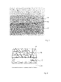
- FIG. 3 shows an image recorded by SEM of a cross section through a surface of a Ni base alloy coated with the ceramic layer
- FIG. 4 shows a schematic view of a cross section through an object
- FIG. 5 shows the adhesiveness of the ceramic layer of a conventional test specimen compared with a test specimen according to the invention
- FIG. 6 a shows an image recorded by SEM of a surface of a test specimen according to the invention without thermal load change
- FIG. 6 b shows the surface according to FIG. 6 a after 20 thermal changes
- FIG. 7 shows the thermal cycle stability of a conventional test specimen compared with test specimens according to the invention
- FIG. 8 shows the coefficient of friction of a conventional test specimen compared with a test specimen according to the invention
- FIG. 9 shows the Vickers microhardness of a conventional test specimen compared with further test specimens according to the invention.
- FIG. 10 shows the porosity of a conventional test specimen compared with further test specimens according to the invention.
- a nitrogen gas reservoir 1 is connected via a first gas control valve 2 to a gas feed line 3 .
- An HCl gas reservoir 4 is likewise connected to the gas feed line 3 via a second gas control valve 5 .
- the gas feed line 3 leads into a furnace 6 .
- a container 7 produced for example from quartz glass and containing a salt melt 8 is received in the furnace 6 .
- the container 7 is advantageously coated with YSZ (not shown here) on its inner face facing the salt melt 8 .
- the salt melt 8 can be formed in equimolar composition from KCl—K 2 SO 4 —ZnCl 2 —ZnSO 4 , for example.
- Reference sign 9 denotes a gas inlet or a mouth of the gas feed line 3 .
- Reference sign 10 denotes a gas outlet or an end of a gas discharge line 11 .
- test specimen 12 is arranged above the salt melt 8 in the furnace 6 .
- the test specimen may be a steel cylinder that is coated with a Ni base alloy, wherein the Ni base alloy is in turn coated with a ceramic layer made of YSZ applied by means of thermal spraying.
- the gas discharge line 11 leads into a first container 13 , in which a drying agent is received.
- the dried waste gas is transferred from the first container 13 via a second gas discharge line 14 into a second container 15 , in which a lye is received.
- the dried and neutralised waste gas is discharged via a waste gas line 16 .
- FIG. 2 shows the solubility of ZrO 2 depending on the temperature and depending on the composition of the gas phase.
- ZrO 2 has a maximum solubility at a temperature of the melt of 700° C.
- the measurement result indicated by a triangle shows that ZrO 2 hardly dissolves in the salt melt with an omission of HCl in the carrier gas or an omission of sulphate salts.
- test specimen bodies formed from YSZ were each treated in a predefined quantity of the salt melt 8 for 72 hours at the temperature specified in each case.
- the salt melt 8 was then analysed quantitatively by means of ICPMS.
- FIG. 3 shows an image recorded by SEM of a cross section through a test specimen treated in accordance with the invention.
- Reference sign 17 denotes a conventional Ni base alloy, for example alloy 625.
- the Ni base alloy contains 20 to 23% by weight Cr and 8 to 10% by weight molybdenum and, as further constituents, tantalum in particular.
- Reference sign 18 denotes a ceramic layer that is produced from YSZ.
- An intermediate layer 19 is arranged between the Ni base alloy 17 and the ceramic layer 18 and here has a thickness from approximately 1.0 to 3.0 ⁇ m.
- the intermediate layer 19 is the result of the proposed solvothermal treatment of the test specimen. According to initial findings, it basically contains chromium oxides, possibly also proportions of chromium sulphides. If the ceramic layer as further main constituent also contains Al 2 O 3 besides ZrO 2 , Al 2 O 3 is then probably also contained in the intermediate layer 19 besides ZrO 2 .
- FIG. 4 shows a schematic cross section through an object that forms a substrate 20 .
- the substrate 20 can be produced from steel, for example.
- the substrate 20 can be coated at least in portions with the Ni base alloy 17 , which is in turn covered by the ceramic layer 18 .
- the intermediate layer 19 is formed between the Ni base alloy 17 and the ceramic layer 18 as a result of the solvothermal treatment according to the invention of the test specimen.
- the table below shows the dependency of the densification rate in the region of the ceramic layer 18 on temperature, HCl content in the gas phase and sulphate proportion in the salt melt 8 , wherein the system KCl—K 2 SO 4 —ZnCl 2 —ZnSO 4 was used as salt melt and N 2 was used as carrier gas:
- FIG. 5 shows the results of measurements of the adhesiveness of a ceramic layer made of YSZ which has been applied by means of plasma spraying to the Ni base alloy, alloy 625.
- an intermediate layer 19 with a thickness of approximately 1.0 ⁇ m has formed.
- the adhesiveness of the solvothermally treated test specimen is approximately twice that of the conventional test specimen.
- FIGS. 6 a , 6 b and 7 show the results of the thermal cycle stability of the aforementioned test specimens.
- the thermal cycle stability has been determined by means of SEM images of the surfaces.
- FIG. 6 a shows the surface of a solvothermally treated test specimen prior to the start of the thermal load change cycles.
- FIG. 6 b shows the same surface after 20 thermal load change cycles.
- flaking of the ceramic layer is observed with untreated test specimens after just 2 thermal load change cycles.
- the thermal cycle stability was defined as the moment in time at which 20% of the ceramic layer exhibited flaking.
- some of the solvothermally treated test specimens demonstrate a drastically improved thermal shock resistance compared with the untreated test specimen.
- FIG. 8 shows the tribological properties of a conventional test specimen and a solvothermally treated test specimen, of which the ceramic layer was again produced from YSZ.
- the measurement results shown in FIG. 8 were measured by means of a ball-on-disc tribometer in a “three ball on disc test”.
- the test specimens treated in accordance with the invention demonstrate a coefficient of friction that is reduced by a factor of 3.
- FIGS. 9 and 10 concern results of tests on further test specimens, in which the ceramic layer was produced in each case from an equimolar mixture of YSZ and Al 2 O 3 .
- the ceramic layer was in turn applied by means of plasma spraying to a substrate made of a Ni base alloy, alloy 625.
- the solvothermal post-treatment was again performed with use of the model system described with reference to FIG. 2 at a temperature of 700° C.
- the solvothermally treated test specimens demonstrate a considerably improved Vickers microhardness. It can be seen from FIG. 10 that the solvothermally treated test specimens additionally have a drastically reduced porosity.
- the reduction of porosity occurs with the solvothermally treated test specimens since YSZ and/or Al 2 O 3 dissolve as a result of the action of the gas phase and diffuse in the direction of the interface formed by the Ni base alloy. There, recrystallisation of the dissolved ceramic phase takes place, whereby in particular the pore space of the ceramic layer in the region of the interface is filled.
- the solvothermally treated test specimens thus are not characterised just by the formation of an intermediate layer between the Ni base alloy and the ceramic layer, but also by a porosity within the ceramic layer decreasing from the layer surface of the ceramic layer in the direction of the interface.
- Conventional layers produced by means of thermal spraying generally have a porosity in the region of 9%.
- solvothermally treated ceramic layers have a drastically reduced porosity in the range from 3 to 5.50.
- the specified porosities relate here again to results obtained by means of image evaluation on a micrograph.
Landscapes
- Chemical & Material Sciences (AREA)
- Engineering & Computer Science (AREA)
- Mechanical Engineering (AREA)
- Materials Engineering (AREA)
- Chemical Kinetics & Catalysis (AREA)
- Metallurgy (AREA)
- Organic Chemistry (AREA)
- Physics & Mathematics (AREA)
- Plasma & Fusion (AREA)
- General Chemical & Material Sciences (AREA)
- General Engineering & Computer Science (AREA)
- Ceramic Engineering (AREA)
- Inorganic Chemistry (AREA)
- Coating By Spraying Or Casting (AREA)
- Other Surface Treatments For Metallic Materials (AREA)
- Turbine Rotor Nozzle Sealing (AREA)
- Ceramic Products (AREA)
- Physical Vapour Deposition (AREA)
Abstract
Description
| Temperature (° C.) | ||
| 500 | 600 | 700 | 700 | 700 | 700 | ||
| |
2% | 2% | 2% | 4% | 8% | 2% |
| proportion | ||||||
| Sulphate | 50% | 50% | 50% | 50% | 50% | 44% |
| proportion | ||||||
| Densifi- | <5 μm/d | <5 μm/d | 130 μm/d | <10 μm/d | <5 μm/d | 40 μm/d |
| cation rate | ||||||
- 1 nitrogen gas reservoir
- 2 first gas control valve
- 3 gas feed line
- 4 HCl gas reservoir
- 5 second gas control valve
- 6 furnace
- 7 container
- 8 salt melt
- 9 gas inlet
- 10 gas outlet
- 11 gas discharge line
- 12 test specimen
- 13 first container
- 14 further gas discharge line
- 15 second container
- 16 waste gas line
- 17 Ni base alloy
- 18 ceramic layer
- 19 intermediate layer
- 20 substrate
Claims (13)
Applications Claiming Priority (4)
| Application Number | Priority Date | Filing Date | Title |
|---|---|---|---|
| DE201210200560 DE102012200560B4 (en) | 2012-01-16 | 2012-01-16 | A method of producing a ceramic layer on a surface formed of a Ni-based alloy and a ceramic layer article |
| DE102012200560.9 | 2012-01-16 | ||
| DE102012200560 | 2012-01-16 | ||
| PCT/EP2013/050577 WO2013107712A1 (en) | 2012-01-16 | 2013-01-14 | Method for producing a ceramic layer on a surface formed from an ni base alloy |
Publications (2)
| Publication Number | Publication Date |
|---|---|
| US20150056436A1 US20150056436A1 (en) | 2015-02-26 |
| US9920414B2 true US9920414B2 (en) | 2018-03-20 |
Family
ID=47598801
Family Applications (1)
| Application Number | Title | Priority Date | Filing Date |
|---|---|---|---|
| US14/372,391 Expired - Fee Related US9920414B2 (en) | 2012-01-16 | 2013-01-14 | Method for producing a ceramic layer on a surface formed from an Ni base alloy |
Country Status (6)
| Country | Link |
|---|---|
| US (1) | US9920414B2 (en) |
| EP (1) | EP2805021B1 (en) |
| JP (1) | JP2015513605A (en) |
| CA (1) | CA2861275C (en) |
| DE (1) | DE102012200560B4 (en) |
| WO (1) | WO2013107712A1 (en) |
Families Citing this family (2)
| Publication number | Priority date | Publication date | Assignee | Title |
|---|---|---|---|---|
| US11242256B2 (en) | 2018-06-01 | 2022-02-08 | Imam Abdulrahman Bin Faisal University | Multi-stage calcination method for making hollow silica spheres |
| CN110983230A (en) * | 2019-12-23 | 2020-04-10 | 广州市尤特新材料有限公司 | Heat-insulating coating of electromagnetic pot and preparation method thereof |
Citations (15)
| Publication number | Priority date | Publication date | Assignee | Title |
|---|---|---|---|---|
| US4966820A (en) | 1988-05-06 | 1990-10-30 | Hitachi, Ltd. | Ceramics-coated heat resisting alloy member |
| US5035957A (en) * | 1981-11-27 | 1991-07-30 | Sri International | Coated metal product and precursor for forming same |
| EP0605196A1 (en) | 1992-12-29 | 1994-07-06 | General Electric Company | Thermal barrier coating process |
| EP0816526A2 (en) | 1996-06-27 | 1998-01-07 | United Technologies Corporation | Insulating thermal barrier coating system |
| US5955182A (en) | 1996-02-05 | 1999-09-21 | Kabushiki Kaisha Toshiba | Heat resisting member and its production method |
| DE19918900A1 (en) | 1998-04-27 | 1999-10-28 | Toshiba Kawasaki Kk | High temperature component, especially metallic gas turbine component |
| US6328818B1 (en) * | 1997-11-28 | 2001-12-11 | Maizuru Corporation | Method for treating surface of ferrous material and salt bath furnace used therefor |
| US6565820B1 (en) * | 1999-05-20 | 2003-05-20 | University Technology Corporation | Low temperature oxidation using support molten salt catalysts |
| US20030203224A1 (en) | 2001-07-30 | 2003-10-30 | Diconza Paul Josesh | Thermal barrier coating of intermediate density |
| EP1591550A1 (en) | 2004-04-28 | 2005-11-02 | United Technologies Corporation | Thermal barrier coating having an interfacial layer for spallation life enhancement and low conductivity |
| EP1640477A2 (en) | 2004-09-28 | 2006-03-29 | Hitachi, Ltd. | High temperature component with thermal barrier coating and gas turbine using the same |
| EP1829984A1 (en) | 2006-03-01 | 2007-09-05 | United Technologies Corporation | High Density Thermal Barrier Coating |
| WO2007112783A1 (en) | 2006-04-06 | 2007-10-11 | Siemens Aktiengesellschaft | Layered thermal barrier coating with a high porosity, and a component |
| US20080145629A1 (en) | 2006-12-15 | 2008-06-19 | Siemens Power Generation, Inc. | Impact resistant thermal barrier coating system |
| EP2309024A2 (en) | 2009-10-12 | 2011-04-13 | General Electric Company | Process of forming a coating system, coating system formed thereby, and components coated therewith |
Family Cites Families (3)
| Publication number | Priority date | Publication date | Assignee | Title |
|---|---|---|---|---|
| JP2697469B2 (en) * | 1992-04-03 | 1998-01-14 | 株式会社日立製作所 | Gas turbine blades, vanes and combustor liners and manufacturing method |
| JP3332847B2 (en) * | 1998-03-17 | 2002-10-07 | 株式会社東芝 | Heat resistant member and method of manufacturing heat resistant member |
| JP4616648B2 (en) * | 2002-09-25 | 2011-01-19 | ボルボ エアロ コーポレイション | Thermal barrier coating and method of applying such a coating |
-
2012
- 2012-01-16 DE DE201210200560 patent/DE102012200560B4/en not_active Expired - Fee Related
-
2013
- 2013-01-14 WO PCT/EP2013/050577 patent/WO2013107712A1/en not_active Ceased
- 2013-01-14 CA CA2861275A patent/CA2861275C/en not_active Expired - Fee Related
- 2013-01-14 JP JP2014552593A patent/JP2015513605A/en active Pending
- 2013-01-14 EP EP13700865.2A patent/EP2805021B1/en not_active Not-in-force
- 2013-01-14 US US14/372,391 patent/US9920414B2/en not_active Expired - Fee Related
Patent Citations (21)
| Publication number | Priority date | Publication date | Assignee | Title |
|---|---|---|---|---|
| US5035957A (en) * | 1981-11-27 | 1991-07-30 | Sri International | Coated metal product and precursor for forming same |
| US4966820A (en) | 1988-05-06 | 1990-10-30 | Hitachi, Ltd. | Ceramics-coated heat resisting alloy member |
| DE68911363T2 (en) | 1988-05-06 | 1994-06-09 | Hitachi Ltd | Ceramic-coated heat-resistant alloy component. |
| EP0605196A1 (en) | 1992-12-29 | 1994-07-06 | General Electric Company | Thermal barrier coating process |
| US5955182A (en) | 1996-02-05 | 1999-09-21 | Kabushiki Kaisha Toshiba | Heat resisting member and its production method |
| EP0816526A2 (en) | 1996-06-27 | 1998-01-07 | United Technologies Corporation | Insulating thermal barrier coating system |
| US6328818B1 (en) * | 1997-11-28 | 2001-12-11 | Maizuru Corporation | Method for treating surface of ferrous material and salt bath furnace used therefor |
| DE19918900A1 (en) | 1998-04-27 | 1999-10-28 | Toshiba Kawasaki Kk | High temperature component, especially metallic gas turbine component |
| US6398503B1 (en) | 1998-04-27 | 2002-06-04 | Kabushiki Kaisha Toshiba | High temperature component, gas turbine high temperature component and manufacturing method thereof |
| US6565820B1 (en) * | 1999-05-20 | 2003-05-20 | University Technology Corporation | Low temperature oxidation using support molten salt catalysts |
| US20030203224A1 (en) | 2001-07-30 | 2003-10-30 | Diconza Paul Josesh | Thermal barrier coating of intermediate density |
| EP1591550A1 (en) | 2004-04-28 | 2005-11-02 | United Technologies Corporation | Thermal barrier coating having an interfacial layer for spallation life enhancement and low conductivity |
| US7326470B2 (en) | 2004-04-28 | 2008-02-05 | United Technologies Corporation | Thin 7YSZ, interfacial layer as cyclic durability (spallation) life enhancement for low conductivity TBCs |
| EP1640477A2 (en) | 2004-09-28 | 2006-03-29 | Hitachi, Ltd. | High temperature component with thermal barrier coating and gas turbine using the same |
| US7901790B2 (en) | 2004-09-28 | 2011-03-08 | Hitachi, Ltd. | High temperature component with thermal barrier coating and gas turbine using the same |
| EP1829984A1 (en) | 2006-03-01 | 2007-09-05 | United Technologies Corporation | High Density Thermal Barrier Coating |
| US20070207328A1 (en) | 2006-03-01 | 2007-09-06 | United Technologies Corporation | High density thermal barrier coating |
| WO2007112783A1 (en) | 2006-04-06 | 2007-10-11 | Siemens Aktiengesellschaft | Layered thermal barrier coating with a high porosity, and a component |
| US20090311508A1 (en) | 2006-04-06 | 2009-12-17 | Werner Stamm | Layered thermal barrier coating with a high porosity, and a component |
| US20080145629A1 (en) | 2006-12-15 | 2008-06-19 | Siemens Power Generation, Inc. | Impact resistant thermal barrier coating system |
| EP2309024A2 (en) | 2009-10-12 | 2011-04-13 | General Electric Company | Process of forming a coating system, coating system formed thereby, and components coated therewith |
Non-Patent Citations (9)
| Title |
|---|
| Fehr et al., "Ein neues Verfahren zur Optimierung oxidkeamischer Schutzschichten", Moderne Beschichtungen zum Verschleiβschutz von Werkzeugen, Faulstich et al., Eds., Dorner PrintConcept GmbH & Co. 2012, vol. 7. pp. 51-78. |
| Guo, H.B. et al., "Atmospheric plasma sprayed thick thermal barrier coatings with high segmentation crack density," Surface & Coatings Technology, 2004, p. 353-363, vol. 186, Elsevier. |
| Lima, C.R.C. et al., "Temperature Measurements and Adhesion Properties of Plasma Sprayed Thermal Barrier Coatings," Journal of Thermal Spray Technology, 1999, p. 323-327, vol. 8, ASM International. |
| Masset, et al "Chemical densification of oxide based coatings for high temperature wear and corrosion resistance", Abstract #2336, Honolulu PRiME 2012, © 2012 The Electrochemical Society, 1 page. * |
| PCT, "International Preliminary Report on Patentability for International Application No. PCT/EP2013/050577.", dated 2014. |
| Portinha, A. et al., "Characterization of thermal barrier coatings with a gradient in porosity," Surface & Coatings Technology, 2005, pp. 245-251, vol. 195, Elsevier. |
| Steffens, H.-D et al., "Some Aspects of Thick Thermal Barrier Coating Lifetime Prolongation," Journal of Thermal Spray Technology, 1999, p. 517-522, vol. 8, ASM International. |
| Ye et al., "Chemical Densification of plasma sprayed ytteria stabilized zirconia (YSZ) coatings for high temperature wear and corrosion resistance", Applied Surface Science 263 (2017) 827. |
| Yoshiba, M. et al., "High-Temperature Oxidation and Hot Corrosion Behavior of Two Kinds of Thermal Barrier Coating Systems for Advanced Gas Turbines," Journal of Thermal Spray Technology, 1996, p. 259-268, vol. 5, ASM International. |
Also Published As
| Publication number | Publication date |
|---|---|
| EP2805021B1 (en) | 2020-10-28 |
| EP2805021A1 (en) | 2014-11-26 |
| DE102012200560A1 (en) | 2013-07-18 |
| US20150056436A1 (en) | 2015-02-26 |
| DE102012200560A8 (en) | 2014-02-27 |
| JP2015513605A (en) | 2015-05-14 |
| CA2861275C (en) | 2020-09-15 |
| WO2013107712A1 (en) | 2013-07-25 |
| DE102012200560B4 (en) | 2014-08-21 |
| CA2861275A1 (en) | 2013-07-25 |
Similar Documents
| Publication | Publication Date | Title |
|---|---|---|
| Rodriguez et al. | Comparison of aluminum coatings deposited by flame spray and by electric arc spray | |
| US9023486B2 (en) | Thermal barrier coating systems and processes therefor | |
| CA2851281C (en) | Thermal barrier coating systems and processes therefor | |
| Mohammadi et al. | Evaluation of hot corrosion behaviors of Al2O3-YSZ composite TBC on gradient MCrAlY coatings in the presence of Na2SO4-NaVO3 salt | |
| Jam et al. | Evaluation of microstructure and electrochemical behavior of dual-layer NiCrAlY/mullite plasma sprayed coating on high silicon cast iron alloy | |
| Ruiz-Luna et al. | Effect of HVOF processing parameters on the properties of NiCoCrAlY coatings by design of experiments | |
| JP2008045211A (en) | Turbine engine component, and coating method thereof | |
| Mohammadi et al. | Characterization and hot corrosion performance of LVPS and HVOF-CoNiCrAlYSi coatings | |
| Zhang et al. | Oxidation and hot corrosion behavior of plasma-sprayed MCrAlY–Cr2O3 coatings | |
| Bal et al. | The effect of CMAS interaction on thermal cycle lifetime of YSZ based thermal barrier coatings | |
| Zouari et al. | Comparative study of HVOF-sprayed NiCrBSi alloy and 316L stainless steel coatings on a brass substrate | |
| Pathak et al. | Thermal spray coatings for blast furnace tuyere application | |
| US9920414B2 (en) | Method for producing a ceramic layer on a surface formed from an Ni base alloy | |
| Gurr et al. | Investigation of the corrosion behavior of NiVAl multilayer coatings in hot salt melts | |
| Alroy et al. | Understanding the thermal barrier performance of plasma-sprayed rare-earth zirconate coating against volcanic ash ingestion | |
| Shao et al. | Corrosion behavior and mechanical properties of plasma sprayed Al2O3-aluminum bronze and Ca2SiO4-aluminum bronze coatings | |
| Zhang et al. | Corrosive wear mechanism of supersonic atmospheric plasma spray coating of hydraulic supports in industrial environment | |
| Singh et al. | Hot corrosion behavior of cold-sprayed Ni-50Cr coating in an incinerator environment at 900 C | |
| Gómez et al. | Influence of Iron Oxide Deposits on the Hot Corrosion Resistance of YSZ Thermal Barrier Coatings in Molten Vanadium Pentoxide | |
| Sharma et al. | Oxidation behaviour of D-gun sprayed Al2O3-3 wt% SiC coating | |
| Song et al. | Corrosion behavior of thermal barrier coatings exposed to NaCl plus water vapor at 1050 C | |
| Chawla | Microstructural Characteristics and Mechanical Properties of Nanostructured and Conventional TiAlN and AlCrN Coatings on ASTM‐SA210 Grade A‐1 Boiler Steel | |
| Zhang et al. | Hot corrosion behavior of low-pressure cold-sprayed CoNiCrAlY coatings | |
| Manojkumar et al. | Influence of Secondary Ceramic Additives on the Tribological Performance of Plasma Sprayed Cr2O3 Composite Coating | |
| Singh | Fabrication of High-Pressure Cold-Sprayed Coating on Ni-Based Superalloy for High-Temperature Corrosive Conditions |
Legal Events
| Date | Code | Title | Description |
|---|---|---|---|
| AS | Assignment |
Owner name: FRAUNHOFER-GESELLSCHAFT ZUR FOERDERUNG DER ANGEWAN Free format text: ASSIGNMENT OF ASSIGNORS INTEREST;ASSIGNORS:REPRESENTATIVE OF ASSIGNEE FOR INVENTOR, KARL THOMAS FEHR;YE, YAPING;WOLF, GERHARD;SIGNING DATES FROM 20080115 TO 20150226;REEL/FRAME:044598/0507 |
|
| STCF | Information on status: patent grant |
Free format text: PATENTED CASE |
|
| MAFP | Maintenance fee payment |
Free format text: PAYMENT OF MAINTENANCE FEE, 4TH YEAR, LARGE ENTITY (ORIGINAL EVENT CODE: M1551); ENTITY STATUS OF PATENT OWNER: LARGE ENTITY Year of fee payment: 4 |
|
| FEPP | Fee payment procedure |
Free format text: MAINTENANCE FEE REMINDER MAILED (ORIGINAL EVENT CODE: REM.); ENTITY STATUS OF PATENT OWNER: LARGE ENTITY |